EP3671901A1 - Battery module comprising bus bar assembly - Google Patents
Battery module comprising bus bar assembly Download PDFInfo
- Publication number
- EP3671901A1 EP3671901A1 EP18873468.5A EP18873468A EP3671901A1 EP 3671901 A1 EP3671901 A1 EP 3671901A1 EP 18873468 A EP18873468 A EP 18873468A EP 3671901 A1 EP3671901 A1 EP 3671901A1
- Authority
- EP
- European Patent Office
- Prior art keywords
- bus bar
- insulating frame
- battery module
- insulating
- electrode leads
- Prior art date
- Legal status (The legal status is an assumption and is not a legal conclusion. Google has not performed a legal analysis and makes no representation as to the accuracy of the status listed.)
- Pending
Links
Images


Classifications
-
- H—ELECTRICITY
- H01—ELECTRIC ELEMENTS
- H01M—PROCESSES OR MEANS, e.g. BATTERIES, FOR THE DIRECT CONVERSION OF CHEMICAL ENERGY INTO ELECTRICAL ENERGY
- H01M50/00—Constructional details or processes of manufacture of the non-active parts of electrochemical cells other than fuel cells, e.g. hybrid cells
- H01M50/50—Current conducting connections for cells or batteries
- H01M50/502—Interconnectors for connecting terminals of adjacent batteries; Interconnectors for connecting cells outside a battery casing
-
- H—ELECTRICITY
- H01—ELECTRIC ELEMENTS
- H01R—ELECTRICALLY-CONDUCTIVE CONNECTIONS; STRUCTURAL ASSOCIATIONS OF A PLURALITY OF MUTUALLY-INSULATED ELECTRICAL CONNECTING ELEMENTS; COUPLING DEVICES; CURRENT COLLECTORS
- H01R11/00—Individual connecting elements providing two or more spaced connecting locations for conductive members which are, or may be, thereby interconnected, e.g. end pieces for wires or cables supported by the wire or cable and having means for facilitating electrical connection to some other wire, terminal, or conductive member, blocks of binding posts
- H01R11/03—Individual connecting elements providing two or more spaced connecting locations for conductive members which are, or may be, thereby interconnected, e.g. end pieces for wires or cables supported by the wire or cable and having means for facilitating electrical connection to some other wire, terminal, or conductive member, blocks of binding posts characterised by the relationship between the connecting locations
- H01R11/09—Individual connecting elements providing two or more spaced connecting locations for conductive members which are, or may be, thereby interconnected, e.g. end pieces for wires or cables supported by the wire or cable and having means for facilitating electrical connection to some other wire, terminal, or conductive member, blocks of binding posts characterised by the relationship between the connecting locations the connecting locations being identical
-
- H—ELECTRICITY
- H01—ELECTRIC ELEMENTS
- H01M—PROCESSES OR MEANS, e.g. BATTERIES, FOR THE DIRECT CONVERSION OF CHEMICAL ENERGY INTO ELECTRICAL ENERGY
- H01M50/00—Constructional details or processes of manufacture of the non-active parts of electrochemical cells other than fuel cells, e.g. hybrid cells
- H01M50/20—Mountings; Secondary casings or frames; Racks, modules or packs; Suspension devices; Shock absorbers; Transport or carrying devices; Holders
- H01M50/204—Racks, modules or packs for multiple batteries or multiple cells
- H01M50/207—Racks, modules or packs for multiple batteries or multiple cells characterised by their shape
- H01M50/211—Racks, modules or packs for multiple batteries or multiple cells characterised by their shape adapted for pouch cells
-
- H—ELECTRICITY
- H01—ELECTRIC ELEMENTS
- H01M—PROCESSES OR MEANS, e.g. BATTERIES, FOR THE DIRECT CONVERSION OF CHEMICAL ENERGY INTO ELECTRICAL ENERGY
- H01M50/00—Constructional details or processes of manufacture of the non-active parts of electrochemical cells other than fuel cells, e.g. hybrid cells
- H01M50/50—Current conducting connections for cells or batteries
- H01M50/502—Interconnectors for connecting terminals of adjacent batteries; Interconnectors for connecting cells outside a battery casing
- H01M50/503—Interconnectors for connecting terminals of adjacent batteries; Interconnectors for connecting cells outside a battery casing characterised by the shape of the interconnectors
-
- H—ELECTRICITY
- H01—ELECTRIC ELEMENTS
- H01M—PROCESSES OR MEANS, e.g. BATTERIES, FOR THE DIRECT CONVERSION OF CHEMICAL ENERGY INTO ELECTRICAL ENERGY
- H01M50/00—Constructional details or processes of manufacture of the non-active parts of electrochemical cells other than fuel cells, e.g. hybrid cells
- H01M50/50—Current conducting connections for cells or batteries
- H01M50/502—Interconnectors for connecting terminals of adjacent batteries; Interconnectors for connecting cells outside a battery casing
- H01M50/507—Interconnectors for connecting terminals of adjacent batteries; Interconnectors for connecting cells outside a battery casing comprising an arrangement of two or more busbars within a container structure, e.g. busbar modules
-
- H—ELECTRICITY
- H01—ELECTRIC ELEMENTS
- H01M—PROCESSES OR MEANS, e.g. BATTERIES, FOR THE DIRECT CONVERSION OF CHEMICAL ENERGY INTO ELECTRICAL ENERGY
- H01M50/00—Constructional details or processes of manufacture of the non-active parts of electrochemical cells other than fuel cells, e.g. hybrid cells
- H01M50/50—Current conducting connections for cells or batteries
- H01M50/531—Electrode connections inside a battery casing
- H01M50/533—Electrode connections inside a battery casing characterised by the shape of the leads or tabs
-
- H—ELECTRICITY
- H01—ELECTRIC ELEMENTS
- H01R—ELECTRICALLY-CONDUCTIVE CONNECTIONS; STRUCTURAL ASSOCIATIONS OF A PLURALITY OF MUTUALLY-INSULATED ELECTRICAL CONNECTING ELEMENTS; COUPLING DEVICES; CURRENT COLLECTORS
- H01R13/00—Details of coupling devices of the kinds covered by groups H01R12/70 or H01R24/00 - H01R33/00
- H01R13/46—Bases; Cases
- H01R13/502—Bases; Cases composed of different pieces
- H01R13/512—Bases; Cases composed of different pieces assembled by screw or screws
-
- H—ELECTRICITY
- H01—ELECTRIC ELEMENTS
- H01R—ELECTRICALLY-CONDUCTIVE CONNECTIONS; STRUCTURAL ASSOCIATIONS OF A PLURALITY OF MUTUALLY-INSULATED ELECTRICAL CONNECTING ELEMENTS; COUPLING DEVICES; CURRENT COLLECTORS
- H01R25/00—Coupling parts adapted for simultaneous co-operation with two or more identical counterparts, e.g. for distributing energy to two or more circuits
- H01R25/16—Rails or bus-bars provided with a plurality of discrete connecting locations for counterparts
- H01R25/161—Details
- H01R25/162—Electrical connections between or with rails or bus-bars
-
- Y—GENERAL TAGGING OF NEW TECHNOLOGICAL DEVELOPMENTS; GENERAL TAGGING OF CROSS-SECTIONAL TECHNOLOGIES SPANNING OVER SEVERAL SECTIONS OF THE IPC; TECHNICAL SUBJECTS COVERED BY FORMER USPC CROSS-REFERENCE ART COLLECTIONS [XRACs] AND DIGESTS
- Y02—TECHNOLOGIES OR APPLICATIONS FOR MITIGATION OR ADAPTATION AGAINST CLIMATE CHANGE
- Y02E—REDUCTION OF GREENHOUSE GAS [GHG] EMISSIONS, RELATED TO ENERGY GENERATION, TRANSMISSION OR DISTRIBUTION
- Y02E60/00—Enabling technologies; Technologies with a potential or indirect contribution to GHG emissions mitigation
- Y02E60/10—Energy storage using batteries
Definitions
- the present disclosure relates to a battery module including a bus bar assembly, and more particularly, to a battery module including a bus bar assembly having improved productivity because rework is easy when a failure occurs.
- Such a lithium secondary battery mainly uses a lithium-based oxide and a carbon material respectively as a positive electrode active material and a negative electrode active material.
- the lithium secondary battery includes an electrode assembly, in which a positive electrode plate and a negative electrode plate on which the positive electrode active material and the negative electrode active material are respectively coated are arranged with a separator therebetween, and an exterior material, i.e., a battery pouch exterior material, sealing and accommodating the electrode assembly with an electrolyte solution.
- the lithium secondary battery may be classified into a can-type secondary battery, in which the electrode assembly is embedded in a metal can, and a pouch-type secondary battery, in which the electrode assembly is embedded in a pouch of an aluminum laminate sheet, according to a shape of the exterior material.
- the secondary battery is widely used not only in a small-sized apparatus, such as a portable electronic device, but also in medium- and large-sized apparatuses, such as a vehicle or an energy storage apparatus.
- a large number of secondary batteries are electrically connected to increase capacity and output.
- the pouch-type secondary battery is mostly used in such medium- and large-sized apparatuses due to easy stacking.
- electrode leads may be connected to each other and a connected portion may be welded to maintain such a connected state.
- the battery module may have parallel and/or series electric connection between the secondary batteries, and in this case, one end portion of the electrode lead may contact and be fixed to a bus bar for electric connection between the secondary batteries, via welding or the like.
- the electric connection between the secondary batteries is often configured by bonding the electrode lead to the bus bar.
- the electrode leads of same polarity are connected and bonded to each other, and in order to electrically connect the plurality of secondary batteries in series, the electrode leads of different polarities are connected and bonded to each other.
- the electrode lead is formed of a fragile material, while detaching or re-bonding the combined electrode lead for rework due to poor bonding or mis-bonding between the electrode lead and the bus bar, it is difficult for an operator to perform the rework because the electrode lead is very easily damaged.
- the bent electrode lead causes a spring-back phenomenon, and thus it is difficult to adhere the electrode lead and the bus bar to each other.
- the bending process of the electrode lead is performed manually to bond the electrode lead on the bus bar.
- the quality of weldability varies based on the skill or condition of the operator, the quality of a product may deteriorate.
- the present disclosure is designed to solve the problems of the related art, and therefore the present disclosure is directed to providing a battery module including a bus bar assembly having improved productivity because rework is easy when a failure occurs.
- a battery module including: a cell assembly including a plurality of secondary batteries having an electrode lead formed in a shape protruding in a front-and-back direction and stacked on each other in a left-and-right direction; and a bus bar assembly configured to provide electric connection between the plurality of secondary batteries.
- the bus bar assembly includes: a first insulating frame where one or more insertion portions penetrating from a back surface to a front surface are formed such that a plurality of electrode leads are inserted and comprising an electric insulating material; a second insulating frame mounted on the front surface of the first insulating frame and including an electric insulating material; a first bus bar mounted on the first insulating frame, contacting one of the plurality of electrode leads inserted into each of the one or more insertion portions, the one electrode lead being located at one end of the plurality of electrode leads, and including an electric conductive material; and a second bus bar mounted on the second insulating frame, contacting one of the plurality of electrode leads inserted into each of the one or more insertion portions, which is located at the other end, and including an electric conductive material.
- first bus bar and the second bus bar may include front surfaces, rear surfaces, and side surfaces based on the front-and-back direction.
- the side surfaces of the first bus bar and the second bus bar may contact a left side surface or right side surface of the electrode lead, and at least portions of the side surfaces of the first bus bar and the second bus bar may be positioned to face each other while the plurality of electrode leads are disposed to closely contact each other.
- first bus bar and the second bus bar may have a bar shape extending in an up-and-down direction or a quadrangular frame shape with a hollow center.
- the second insulating frame may include a penetrating portion penetrated from a rear surface to a front surface such that the plurality of electrode leads are inserted.
- the first bus bar may be positioned on the front surface of the first insulating frame and have at least a portion protruding forward to be inserted into the penetrating portion.
- first bus bar may be configured to further protrude forward based on a front surface of the second insulating frame.
- the second bus bar may be positioned on the front surface of the second insulating frame.
- the second bus bar may be positioned at an inner side of the penetrating portion such that the side surface faces a portion of the side surface of the first bus bar.
- the first bus bar may be configured to be positioned at an inner side of an insertion portion formed in the first insulating frame.
- the second bus bar may protrude backward from a rear surface of the second insulating frame and be inserted into the insertion portion of the first insulating frame.
- the bus bar assembly may further include a locking member configured to lock and fix the first insulating frame and the second insulating frame to each other.
- the locking member may include a locking bolt.
- the first insulating frame may include an insertion groove configured such that at least a portion of a round rod of the locking bolt is inserted.
- the second insulating frame may include a penetrating hole configured such that the round rod of the locking bolt is penetrated.
- the locking bolt sequentially may penetrate the penetrating hole of the second insulating frame and be inserted into and fixed to the insertion groove of the first insulating frame.
- the locking member may further include a nut or a bearing inserted into and fixed to the insertion groove and configured such that the locking bolt is inserted and locked.
- each of the first insulating frame and the second insulating frame may include a moving guide portion configured to guide the first insulating frame and the second insulating frame to slide in the left-and-right direction to cross each other.
- the moving guide portion may include: a guide groove recessed backward from a front surface of each of a top portion and bottom portion of the first insulating frame and extending in the left-and-right direction; and a guide protrusion protruding backward from a rear surface of each of a top portion and bottom portion of the second insulating frame and accommodated on an inner surface of the guide groove to move in the left-and-right direction.
- a battery module including: a cell assembly including a plurality of secondary batteries having an electrode lead formed in a shape protruding in a front-and-back direction and stacked on each other in a left-and-right direction; and a bus bar assembly configured to provide electric connection between the plurality of secondary batteries, wherein the bus bar assembly may include: a first insulating frame where one or more insertion portions perforated from a back surface to a front surface are formed such that a plurality of electrode leads are inserted therein while being adhered to each other and including an electric insulating material; a second insulating frame mounted on the front surface of the first insulating frame, where one or more penetrating portions perforated from a rear surface to a front surface are formed such that the plurality of electrode leads are inserted therein while being adhered to each other, and including an electric insulating material; a first bus bar mounted on the first insulating frame, contacting one of the plurality of electrode leads inserted
- a battery pack including at least one battery module.
- a device including the battery pack.
- a battery module is configured such that a first bus bar and a second bus bar of a bus bar assembly contact both side surfaces of a plurality of electrode leads inserted into an insertion portion of a first insulating frame, and thus electric connection between a plurality of secondary batteries and bus bars can be effectively achieved as the first bus bar and the second bus bar contact the both side surfaces such that the plurality of electrode leads are suitably adhered.
- the present disclosure can simplify manufacturing processes and reduce manufacturing costs because a bending process and a bonding process via welding or the like are not required to be performed for contact connection between an electrode lead and bus bar.
- a bus bar assembly can be separated from a battery module without largely damaging the electrode lead when a defect occurs, rework is facilitated and waste of a component due to damage can be reduced.
- the size of a bus bar assembly can be ultimately reduced since not only a second bus bar is stably fixed to a second insulating frame without having to use a separate adhesive member by inserting a portion of the second bus bar into the second insulating frame, but also the volume occupied by the second bus bar in a front-and-back direction is largely reduced compared with the size of the second insulating frame and second bus bar in the front-and-back direction.
- a portion of a second bus bar is positioned at an inner side of a penetrating portion formed in a second insulating frame, the size of a protruding structure of a first bus bur positioned to correspond to one side surface of the second bus bar can be largely reduced, and thus manufacturing costs can be reduced and the bus bar assembly may be manufactured to have a further stable structure.
- a bus bar assembly by positioning a first bus bar at an inner side of an insertion portion formed in a first insulating frame, the volume occupied by the first bus bar in a front-and-back direction can be largely reduced compared to the size of the first insulating frame and first bus bar in the front-and-back direction, thereby ultimately reducing the size of the bus bar assembly.
- a locking member by inserting and fixing a locking bolt to an insertion hole formed in a first insulating frame and a penetrating hole formed in a second insulating frame, the first insulating frame and the second insulating frame can be efficiently and stably combined and fixed to each other.
- a second insulating frame can easily slide on a first insulating frame by using a configuration of a guide groove and a guide protrusion, not only position setting for locking the first insulating frame and the second insulating frame is facilitated, but also a work of interposing a plurality of electrode leads between a first bus bar and a second bus bar is facilitated.
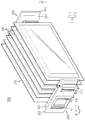
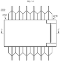
- FIG. 1 is a perspective view schematically illustrating a battery module according to an embodiment of the present disclosure.
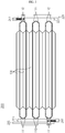
- FIG. 2 is a plan view schematically illustrating a battery module according to an embodiment of the present disclosure.
- a battery module 200 may include a cell assembly 210 including a plurality of secondary batteries 100, and a bus bar assembly 220.
- the secondary battery 100 may be a pouch type secondary battery 100.
- the pouch type secondary battery 100 may include an electrode assembly, an electrolyte solution, and a pouch.
- the pouch may be configured of two pouches, i.e., a left pouch and a right pouch, which have an accommodating portion of a concave shape.
- each pouch includes an external insulating layer, a metal layer, and an internal adhesive layer, and the inner adhesive layers may be adhered to each other at edge regions of the pouches to form a sealing portion.
- the electrode assembly and the electrolyte solution may be accommodated in the accommodating portion.
- the electrode assembly is an assembly of electrodes and a separator, and may be configured in a shape in which one or more positive electrode plates and one or more negative electrode plates are arranged with the separator therebetween.
- a first electrode tab is provided at a first electrode plate of the electrode assembly and one or more first electrode tabs may be connected to a first electrode lead 111.
- the first electrode lead 111 has one end connected to the first electrode tab and the other end exposed to the outside of the pouch, and such an exposed portion may function as an electrode terminal of the secondary battery 100, for example, a positive electrode terminal of the secondary battery 100.
- a second electrode tab is provided at a second electrode plate of the electrode assembly and one or more second electrode tabs may be connected to a second electrode lead 112.
- the second electrode lead 112 has one end connected to the second electrode tab and the other end exposed to the outside of the pouch, and such an exposed portion may function as an electrode terminal of the secondary battery 100, for example, a negative electrode terminal of the secondary battery 100.
- first electrode tab and the second electrode tab included in the secondary battery 100 may be a positive electrode tab or a negative electrode tab
- the first electrode lead 111 and the second electrode lead 112 may be a positive electrode lead or a negative electrode lead.
- first and second electrode leads 111 and 112 may be electrode leads of different polarities.
- the first electrode lead 111 may be a positive electrode lead and the second electrode lead 112 may be a negative electrode lead.
- each secondary battery 100 may be configured such that the first and second electrode leads 111 and 112 having different polarities protrude forward and backward.
- the electrode lead 110 includes the first electrode lead 111 and the second electrode lead 112.
- first and second electrode leads 111 and 112 may be configured in a plate shape.
- first and second electrode leads 111 and 112 may protrude in a horizontal direction while a wide area is erected to face the left and the right.
- the plurality of secondary batteries 100 may be included in the battery module 200 and stacked on each other in at least one direction.
- the plurality of pouch type secondary batteries 100 may be stacked on each other in parallel in a left-and-right direction.
- each pouch type secondary battery 100 may be arranged to be perpendicularly erected approximately on the ground such that, when viewed in a direction indicated by an arrow F (shown in FIG. 1 ), two wide areas are respectively positioned at the left and the right and a sealing portion is positioned at top, bottom, front, and back.
- each secondary battery 100 may be erected in an up-and-down direction.
- up, down, front, back, left, and right directions are based on the direction indicated by the arrow F.
- the battery module 200 according to the present disclosure may employ various secondary batteries 100 well-known at the time of application of the present disclosure.
- FIG. 3 is a front view schematically illustrating a first bus bar and a first insulating frame, which are isolated partial components with respect to a battery module, according to an embodiment of the present disclosure.
- FIG. 4 is a front view schematically illustrating a second bus bar and a second insulating frame, which are isolated partial components with respect to a battery module, according to an embodiment of the present disclosure.
- FIG. 5 is a rear view schematically illustrating a second insulating frame that is an isolated partial component with respect to a battery module, according to an embodiment of the present disclosure.
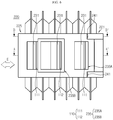
- FIG. 6 is a front view schematically illustrating a battery module according to an embodiment of the present disclosure.
- the bus bar assembly 220 may be configured to provide electric connection between the plurality of secondary batteries 100.
- the bus bar assembly 220 may be positioned at each of the front and back of the cell assembly 210 including the plurality of secondary batteries 100 where the electrode lead 110 is formed on both sides.
- the bus bar assembly 220 may include a first insulating frame 221, a second insulating frame 225, a first bus bar 231, and a second bus bar 235.
- the first insulating frame 221 may include an electric insulating material.
- the electric insulating material may be, for example, a plastic material.
- the first insulating frame 221 may include one or more insertion portion H1 penetrating from a rear surface to a front surface such that the plurality of electrode leads 110 are inserted.
- the insertion portion H1 may have an opening having the size into which the plurality of electrode leads 110 are insertable.
- the insertion portion H1 may have an opening having the size into which the plurality of electrode leads 110 are insertable.
- three insertion portions H1 may be formed in the first insulating frame 221, and each insertion portion H1 may have the opening having the size corresponding to a vertical length of the electrode lead 110.
- the insertion portion H1 may be an opening perforated at an inner side of the first insulating frame 221.
- the plurality of electrode leads 110 may be easily inserted into the insertion portion H1 having such an opening, in the front-and-back direction.
- the insertion portion H1 may be an opening extending from the center of the first insulating frame 221 to an upper end portion or a lower end portion.
- the insertion portion H1 having such a structure since the plurality of electrode leads 110 are not only inserted into the first insulating frame 221 in the front-and-back direction, but also into the center from the upper end portion or the lower end portion of the first insulating frame 221, insertion is facilitated in various directions and thus manufacture efficiency may be increased.
- the second insulating frame 225 may include an electric insulating material.
- the electric insulating material may be, for example, a plastic material.
- the second insulating frame 225 may be mounted on a front surface of the first insulating frame 221.
- the second insulating frame 225 may be configured to slide in a left-and-right direction while being mounted on the front surface of the first insulating frame 221.
- the first bus bar 231 may include an electric conductive material having relatively high electric conductivity.
- the electric conductive material may be copper or aluminum.
- the first bus bar 231 may be mounted on the first insulating frame 221.
- the first bus bar 231 may be fixed while being mounted on the first insulating frame 221.
- a method of fixing the first bus bar 231 to the first insulating frame 221 is not limited to a specific method, and for example, an adhesive may be coated on an outer surface of the first insulating frame 221 and then the first bus bar 231 may be adhered to a region where the adhesive is coated.
- the first bus bar 231 may be configured such as to contact one of the plurality of electrode leads 110 inserted into the insertion portion H1 of the first insulating frame 221.
- the first bus bar 231 may contact one side surface of the electrode lead 110 positioned at one end (a leftmost or rightmost side) among the plurality of electrode leads 110 adhered in the left-and-right direction.
- the second bus bar 235 may be mounted on the second insulating frame 225.
- the second bus bar 235 may be fixed while being mounted on the second insulating frame 225.
- a method of fixing the second bus bar 235 to the second insulating frame 225 is not limited to a particular method, and for example, an adhesive may be coated on an outer surface of the second insulating frame 225 and then the second bus bar 235 may be adhered to a region where the adhesive is coated.
- the second bus bar 235 may be configured to contact one of the plurality of electrode leads 110 inserted into the insertion portion H1 of the second insulating frame 225.
- the second bus bar 235 may contact the other side surface of the electrode lead 110 positioned at the other end (the leftmost or rightmost side) among the plurality of electrode leads 110 adhered in the left-and-right direction.
- the second bus bar 235 may contact the electrode lead 110 positioned at the rightmost side and inserted into the insertion portion H1.
- the first and second bus bars 231 and 235 are able to pressurize, from the both side surfaces, the plurality of electrode leads 110 to be suitably adhered, thereby effectively achieving electric connection between a plurality of secondary batteries and a bus bar.
- FIG. 7 is a partial cross-sectional view schematically illustrating a cross section of a battery module taken along a line A-A' of FIG. 6 .
- the first bus bar 231 may include, based on the front-and-back direction, a front surface 231a, a rear surface 231b, and a side surface 231c.
- the side surface 231c of the first bus bar 231 may contact a left side surface or right side surface of the electrode lead 110.
- the right side surface 231c of the first bus bar 231 may contact a left side surface of the first electrode lead 111.
- the second bus bar 235 may include, based on the front-and-back direction, a front surface 235a, a rear surface 235b, and a side surface 235c.
- the side surface 235c of the second bus bar 235 may contact the left side surface or right side surface of the electrode lead 110.
- the left side surface 235c of the second bus bar 235 may contact a right side surface of the second electrode lead 112.
- first bus bar 231 and the second bus bar 235 may be positioned so that at least the side surfaces thereof at least partially face each other in a state where the plurality of electrode leads 110 are interposed between the first bus bar 231 and the second bus bar 235 and adhered to each other.
- the side surface of the first bus bar 231 may contact one side surface of the electrode lead 110 positioned at the end of the plurality of electrode leads 110 adhered to each other
- the side surface of the second bus bar 235 may contact the other side surface of the electrode lead 110 positioned at the other end of the plurality of electrode leads 110 adhered to each other.
- first and second bus bars 231 and 235 are formed in a structure capable of effectively contacting the one side surface and the other side surface of the plurality of electrode leads 110 adhered to each other, an adhered state between the plurality of electrode leads 110 may be maintained and electric connection between the plurality of secondary batteries 100 may be effectively achieved.
- the first bus bar 231 may have a bar shape extending in the up-and-down direction.
- the first bus bar 231 may be formed in such a manner that the side surface 231c has the size equal to or larger than that of a side H1c of the insertion portion H1.
- the first bus bar 231 may be positioned such that the side surface 231c is parallel to the other side H1c of the insertion portion H1 of the insertion portion H1 when viewed from the front.
- the first bus bar 231 may be positioned such that, when viewed from the front, the side surface 231c and the other side H1c of the insertion portion H1 contact each other.
- the three first bus bars 231 may have a bar shape extending in the up-and-down direction. Also, the three first bus bars 231 may be positioned such that, when viewed from the front, the right side surface 231c overlap the left side H1c of the insertion portion H1.
- the shape of the first bus bar 231 is not necessarily limited to a bar shape, and the first bus bar 231 may have a quadrangular frame shape with a hollow center, like a second bus bar 235B of FIG. 4 .
- the first bus bar 231 includes an upper end portion and a lower end portion extending in the left-and-right direction, and may include a both side portions extending in the up-and-down direction to connect the upper end portion and the lower end portion.
- the first bus bar 231 is formed such that the side surface of the electrode lead 110 inserted through the insertion portion H1 of the first insulating frame 221 is easily contacted, electric connection between the electrode lead 110 and the first bus bar 231 may be easily achieved.
- a second bus bar 235A may have a bar shape extending in the up-and-down direction.
- the second bus bar 235A may be formed such that the side surface 235c thereof may have the size equal to or larger than that of a side H2c of a penetrating portion H2.
- the other side surface 235c of the second bus bar 235A may be positioned to be parallel to the side H2c of the penetrating portion H2 when viewed from the front. In other words, the other side surface 235c of the second bus bar 235A and the side H2c of the penetrating portion H2 may be positioned to contact each other.
- the second bus bar 235B may have a quadrangular frame shape with a hollow center.
- the second bus bar 235B includes an upper end portion 237 and a lower end portion 238 extending in the left-and-right direction, and may include a both side portions 236 extending in the up-and-down direction to connect the upper end portion 237 and the lower end portion 238.
- one second bus bar 235A may have a bar shape extending in the up-and-down direction and one second bus bar 235B may have a quadrangular shape with a hollow center. Also, the two second bus bars 235A and 235B may be positioned such that left side portions thereof overlap the right side H2c of the penetrating portion H2 when viewed from the front.
- the second bus bar 235B is formed to easily contact the side surface of the plurality of electrode leads 110 inserted through the penetrating portion H2 of the second insulating frame 225, and thus electric connection between the plurality of electrode leads 110 and the second bus bar 235B may be easily achieved.
- one or more penetrating portion H2 penetrated from the rear surface to the front surface may be formed such that the plurality of electrode leads 110 are inserted.
- the penetrating portion H2 may have an opening having the size into which the plurality of electrode leads 110 are insertable.
- the second insulating frame 225 may include three penetrating portions H2 and each penetrating portion H2 may have an opening having the size corresponding to a vertical length of the electrode lead 110.
- the penetrating portion H2 may be an opening extending from the center of the second insulating frame 225 to the upper end portion or the lower end portion.
- the plurality of electrode leads 110 are insertable not only to the second insulating frame 225 in the front-and-back direction, but also to the center from the upper end portion or lower end portion of the second insulating frame 225, and thus manufacture efficiency may be increased.
- At least one portion of the penetrating portion H2 may be positioned to face the insertion portion H1 of the first insulating frame 221.
- the electrode lead 110 may be configured to penetrate the insertion portion H1 and then penetrate the penetrating portion H2 again.
- the first bus bar 231 may be positioned at the front surface of the first insulating frame 221.
- the first bus bar 231 may be positioned such that the side surface 231c of the first bus bar 231 and an inner side surface of the first insulating frame 221 are connected in the front-and-back direction.
- the first bus bar 231 may be formed such that at least a portion protrudes forward to be inserted into the penetrating portion H2. Moreover, the first bus bar 231 may protrude to face at least a portion of the second bus bar 235. For example, as shown in FIG. 7 , the first bus bar 231 may protrude to face one side surface of the second bus bar 235.
- the first bus bar 231 may be configured to further protrude forward based on the front surface of the second insulating frame 225.
- the first bus bar 231 may protrude externally by penetrating the insertion portion H1 to correspond to one side surface of the second bus bar 235 while the plurality of electrode leads 110 are disposed.
- the second bus bar 235 may be positioned at the front surface of the second insulating frame 225. Moreover, the second bus bar 235 may be positioned such that the side surface 235c of the second bus bar 235 and an inner side surface of the penetrating portion H2 of the second insulating frame 225 are connected in the front-and-back direction.
- FIG. 8 is a front view schematically illustrating a first bus bar and a first insulating frame, which are isolated partial components with respect to a battery module, according to another embodiment of the present disclosure.
- FIG. 9 is a front view schematically illustrating a second bus bar and a second insulating frame, which are isolated partial components with respect to a battery module, according to another embodiment of the present disclosure.
- FIG. 10 is a front view schematically illustrating a battery module according to another embodiment of the present disclosure.
- FIG. 11 is a partial cross-sectional view schematically illustrating a cross section of a battery module taken along a line A-A' of FIG. 10 .
- configurations of a first insulating frame 221C and a first bus bar 231C of FIG. 8 may be the same as a configuration of the first insulating frame 221 of FIG. 6 according to an embodiment of the present disclosure described above. Accordingly, detailed descriptions about the first insulating frame 221C and the first bus bar 231C of FIG. 8 will be omitted.
- the second bus bar 235 positioned at the front surface of the second insulating frame 225 of FIG. 7
- at least a portion of the second bus bar 235 of FIG. 9 may be positioned inside the penetrating portion H2.
- a side surface of the second bus bar 235 may face at least a portion of a side surface of the first bus bar 231C.
- a portion of the second bus bar 235 may be inserted into a second insulating frame 225C.
- an insert injection method may be used as a method for inserting the portion of the second bus bar 235 into the second insulating frame 225C.
- a method of manufacturing the second insulating frame 225C into which the second bus bar 235 is inserted may include: (a) preparing the second bus bar 235 of electric conductivity, whose external shape is plasticized via press; (b) mounting and fixing the second bus bar 235 inside a mold; and (c) injecting a melted insulating material into the mold to combine with at least a portion of the second bus bar 235 and performing casting by solidifying the melted material.
- the portion of the second bus bar 235 into the second insulating frame 225 by inserting the portion of the second bus bar 235 into the second insulating frame 225, not only the second bus bar 235 second bus bar 235 is stably fixed to the second insulating frame 225C without having to use a separate adhesive member, but also the volume occupied by the second bus bar 235 of FIG. 9 in the front-and-back direction is largely reduced compared with the size of the second insulating frame 225 and second bus bar 235 of FIG. 4 in the front-and-back direction, and thus the size of the bus bar assembly 220C may be ultimately reduced.
- a portion of the second bus bar 235 which is not inserted into the second insulating frame 225C, may be positioned inside the penetrating portion H2.
- the upper end portion 237 and the lower end portion 238 may be inserted into the second insulating frame 225C, and the both side portions 236 connecting the upper end portion 237 and the lower end portion 238 may be positioned inside the penetrating portion H2 of the second insulating frame 225C.
- one side portion 239 may be inserted into the second insulating frame 225C and the other side portion may be externally exposed by being positioned inside the penetrating portion H2.
- the second bus bar 235 of FIG. 9 may be positioned to correspond to the first bus bar 231C positioned at the front surface of the first insulating frame 221C.
- the first bus bar 231C may be positioned to correspond to the side surface of the second bus bar 235 as at least a portion is inserted into the penetrating portion H2 of the second insulating frame 225C.
- the plurality of electrode leads 110 inserted into the insertion portion H1 and the penetrating portion H2 may be disposed on the side surface of the first bus bar 231C and the side surface of the second bus bar 235.
- the bus bar assembly 220C may be manufactured with low material costs and a stable structure.
- FIG. 12 is a front view schematically illustrating a first bus bar and a first insulating frame, which are isolated partial components with respect to a battery module, according to another embodiment of the present disclosure.
- FIG. 13 is a front view schematically illustrating a second bus bar and a second insulating frame, which are isolated partial components with respect to a battery module, according to another embodiment of the present disclosure.
- FIG. 14 is a front view schematically illustrating a battery module according to another embodiment of the present disclosure.
- FIG. 15 is a partial cross-sectional view schematically illustrating a cross section of a battery module taken along a line A-A' of FIG. 14 .
- a bus bar assembly 220D may be configured such that a first bus bar 231D is positioned inside the insertion portion H1 formed in a first insulating frame 221D.
- the first bus bar 231D may be positioned inside the insertion portion H1 without protruding forward based on a front surface of the first insulating frame 221D.
- the volume occupied by the first bus bar 231D of FIG. 12 in the front-and-back direction may be largely reduced compared with the size of the first insulating frame 221 and first bus bar 231 of FIG. 3 in the front-and-back direction, and thus the size of the bus bar assembly 220D may be ultimately reduced.
- first bus bar 231D may be inserted into the first insulating frame 221D such as to be positioned inside the insertion portion H1.
- an insert injection method may be used as a method of inserting the portion of the first bus bar 231D into the first insulating frame 221D
- a method of manufacturing the first insulating frame 221D into which the portion of the first bus bar 23 1D is inserted may include: (a) preparing the first bus bar 231D of electric conductivity, whose external shape is plasticized via press; (b) mounting and fixing the first bus bar 231D inside a mold; and (c) injecting a melted insulating material into the mold to combine with at least a portion of the first bus bar 231D and performing casting by solidifying the melted material.
- the first bus bar 231D may be fixed to the first insulating frame 221D stably without having to use a separate adhesive material.
- the second bus bar 235 of FIG. 13 may protrude backward from a rear surface of a second insulating frame 225D.
- at least a portion of the second bus bar 235 may protrude to be inserted into the insertion portion H1 formed in the first insulating frame 221D while the second bus bar 235 is combined to the second insulating frame 225D.
- the upper end portion 237 and the lower end portion 238 may be inserted into the second insulating frame 225D, and the both side portions 236 connecting the upper end portion 237 and the lower end portion 238 may protrude backward based on a rear surface of the second insulating frame 225D.
- the front end portion 235 a may be inserted into the second insulating frame 225D or a front surface may be adhered to a rear surface of the second insulating frame 225D.
- the rear end portion 235b of the second bus bar 235E may protrude such that at least a portion is inserted into the insertion portion H1 formed in the first insulating frame 221D.
- the second insulating frame 225D of FIG. 13 does not require a separate penetrating portion for inserting the electrode lead 110, and thus has a simple structure and simplified manufacturing processes.
- the second insulating frame 225D that does not include the penetrating portion may effectively protect an internal structure of the bus bar assembly 220D from the outside.
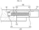
- FIG. 16 is a partial cross-sectional view schematically illustrating a cross section of a battery module taken along a line B-B' of FIG. 6 .
- the bus bar assembly 220 may include a locking member 240 configured such that the first insulating frame 221 and the second insulating frame 225 are locked and fixed to each other.
- the locking member 240 may be configured to such that the first insulating frame 221 and the second insulating frame 225 are locked and fixed to each other while the first insulating frame 221 and the second insulating frame 225 slide in the left-and-right direction indicated by arrows E to cross each other.
- the locking member 240 may lock and fix the first insulating frame 221 and the second insulating frame 225 while the plurality of electrode leads 110 inserted into the insertion portion H1 or into the insertion portion H1 and the penetrating portion H2 are disposed between the first bus bar 231 and the second bus bar 235.
- the second bus bar 235 may pressurize one side of the plurality of electrode leads 110 while moving in direction where the first bus bar 231 is positioned, and the other side of the pressurized plurality of electrode leads 110 may contact a side surface of the first bus bar 231.
- both sides of the plurality of electrode leads 110 inserted into the insertion portion H1 or into the insertion portion H1 and the penetrating portion H2 may be pressurized and fixed by the first bus bar 231 and the second bus bar 235.
- the locking member 240 may include a locking bolt 241.
- the locking bolt 241 may include a head and a round rod extending in one direction from the head.
- a thread may be formed on the round rod.
- the first insulating frame 221 may include an insertion groove G configured such that at least a portion of the round rod of the locking bolt 241 is inserted.
- the insertion groove G may be formed on a side surface portion contacting an outer circumference of the first insulating frame 221.
- the insertion groove G may be formed on the front surface of the first insulating frame 221.
- the second insulating frame 225 may include a penetrating hole H3 through which the round rod of the locking bolt 241 passes.
- the penetrating hole H3 may be formed on a side end portion contacting an outer circumference of the second insulating frame 225.
- the penetrating portion H3 may be formed on a rear surface of the second insulating frame 225.
- the locking bolt 241 may sequentially penetrate the penetrating hole H3 of the second insulating frame 225 and inserted and fixed to the insertion groove G of the first insulating frame 221.
- the insertion groove G may be formed on the front surface of each of the upper end portion and the lower end portion of the first insulating frame 221.
- the penetrating hole H3 may be formed on the rear surface of the second insulating frame 225.
- the two locking bolts 241 may each sequentially penetrate the penetrating hole H3 of the second insulating frame 225 and inserted and fixed to the insertion groove G of the first insulating frame 221.
- the first insulating frame 221 and the second insulating frame 225 may be efficiently and stably combined and fixed to each other.
- the locking member 240 may further include a nut or a bearing 245 inserted and fixed to the insertion groove G.
- the bearing 245 may be configured such that the locking bolt 241 is inserted and locked.
- a moving guide portion 250 configured to guide the first insulating frame 221 and the second insulating frame 225 to slide in the left-and-right direction to cross each other may be formed in the first insulating frame 221 and the second insulating frame 225.
- the moving guide portion 250 may include a guide groove 251 and a guide protrusion 255.
- the guide groove 251 may be recessed backward from the front surface of the first insulating frame 221.
- the guide groove 251 may be a groove having one portion among a front surface recessed backward than the remaining portions.
- the two guide grooves 251 may be formed on a front surface of each of an upper end portion and a lower end portion of the first insulating frame 221.
- the guide groove 251 may extend in the left-and-right direction so as to guide the second insulating frame 225 to slide in the left-and-right direction. Further, the insertion groove G may be formed on a side wall of an end portion where the guide groove 251 is ended.
- the first insulating frame 221 and the second insulating frame 225 may be locked and fixed to each other while the plurality of electrode leads 110 are interposed between the first bus bar 231 and the second bus bar 235.
- the guide protrusion 255 may be formed to protrude backward from the rear surface of the second insulating frame 225. Also, the guide protrusion 255 may be formed to correspond to the guide groove 251 formed on the front surface of the first insulating frame 221. For example, when the guide groove 251 is formed to have a rounded inner surface on a vertical cross section, an outer surface of the guide protrusion 255 may have a round protruding shape. When the guide groove 251 is formed to have an inner surface angulated on the vertical cross section, the outer surface of the guide protrusion 255 may have an angulated protrusion shape.
- the guide protrusion 255 may be accommodated on an inner surface of the guide groove 251 and move in the left-and-right direction.
- the guide protrusion 255 may be formed to move in the left-and-right direction by being accommodated on the inner surface of the guide groove 251 extending in the left-and-right direction.
- the two guide protrusions 255 may be formed on a rear surface of each of the upper end portion and the rear end portion of the second insulating frame 225.
- the moving guide portion 250 enables the second insulating frame 225 to easily slide on the first insulating frame 221 by using configurations of the guide groove 251 and the guide protrusion 255, thereby not only facilitating position setting for locking the first insulating frame 221 and the second insulating frame 225, but also facilitating a work of disposing the plurality of electrode leads 110 between the first bus bar 231 and the second bus bar 235.
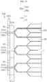
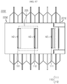
- FIG. 17 is a front view schematically illustrating a battery module according to another embodiment of the present disclosure.
- another bus bar assembly 220E of the present disclosure may include only a part of the plurality of first bus bars 231 and plurality of second bus bars 235, unlike the bus bar assembly 220 of an embodiment described above.
- all of first bus bars of a first insulating frame 221E and a second bus bar of a bar shape of a second insulating frame 225E may not be provided.
- the plurality of electrode leads 110 inserted into an insertion portion (not shown) of the first insulating frame 221E and the penetrating portion H2 of the first insulating frame 221E may overlap each other between the first insulating frame 221E and the second insulating frame 225E.
- the plurality of electrode leads 110 overlap each other between the first insulating frame 221E and the second insulating frame 225E even when some bus bars are omitted, and thus electric connection between the plurality of electrode leads 110 may be achieved.
- first and second bus bars 231 and 235 may be effectively reduced compared with the bus bar assembly 220 of an embodiment described above, and thus material costs may be reduced, thereby effectively reducing unit cost.
- a battery pack (not shown) according to the present disclosure may include at least two battery modules 200.
- the at least two battery modules 200 may be aligned in one direction.
- the battery pack may further include a heat sink (mot shown) for heat dissipation.
- an electronic device may include the battery pack.
- the battery pack may be accommodated inside an outer case of the electronic device.
- the electronic device may be a type of transportation, such as an electric bicycle, or a machine tool.
- Reference Signs 200 battery module 231: first bus bar 210: cell assembly 235: second bus bar 100: secondary battery 240: locking member 110: electrode lead 241: locking bolt 220: bus bar assembly 245: bearing 221: first insulating frame 250: moving guide unit H1: insertion portion 251: guide groove G: insertion groove 255: guide protrusion 225: second insulating frame H2: penetrating portion H3: penetrating hole
- the present disclosure relates to a battery module including a bus bar assembly. Also, the present disclosure is applicable to industries related to a battery pack including a plurality of battery modules and an electric part, an electronic device including the battery pack, an energy storage system, or a vehicle.
Landscapes
- Chemical & Material Sciences (AREA)
- Chemical Kinetics & Catalysis (AREA)
- Electrochemistry (AREA)
- General Chemical & Material Sciences (AREA)
- Connection Of Batteries Or Terminals (AREA)
- Battery Mounting, Suspending (AREA)
Abstract
Description
- The present disclosure relates to a battery module including a bus bar assembly, and more particularly, to a battery module including a bus bar assembly having improved productivity because rework is easy when a failure occurs.
- The present application claims priority to Korean Patent Application No.
10-2017-0146496 filed on November 6, 2017 - Currently commercialized secondary batteries include nickel cadmium batteries, nickel hydrogen batteries, nickel zinc batteries, lithium secondary batteries, etc. and the lithium secondary batteries thereamong are receiving attention according advantages of free charging/discharging, a very low self-discharge rate, and high energy density since a memory effect is barely generated compared to nickel-based secondary batteries.
- Such a lithium secondary battery mainly uses a lithium-based oxide and a carbon material respectively as a positive electrode active material and a negative electrode active material. The lithium secondary battery includes an electrode assembly, in which a positive electrode plate and a negative electrode plate on which the positive electrode active material and the negative electrode active material are respectively coated are arranged with a separator therebetween, and an exterior material, i.e., a battery pouch exterior material, sealing and accommodating the electrode assembly with an electrolyte solution.
- Generally, the lithium secondary battery may be classified into a can-type secondary battery, in which the electrode assembly is embedded in a metal can, and a pouch-type secondary battery, in which the electrode assembly is embedded in a pouch of an aluminum laminate sheet, according to a shape of the exterior material.
- Recently, the secondary battery is widely used not only in a small-sized apparatus, such as a portable electronic device, but also in medium- and large-sized apparatuses, such as a vehicle or an energy storage apparatus. When the secondary battery is used in the medium- and large-sized apparatuses, a large number of secondary batteries are electrically connected to increase capacity and output. In particular, the pouch-type secondary battery is mostly used in such medium- and large-sized apparatuses due to easy stacking.
- In order for the secondary batteries to be electrically connected inside a battery module, electrode leads may be connected to each other and a connected portion may be welded to maintain such a connected state. Moreover, the battery module may have parallel and/or series electric connection between the secondary batteries, and in this case, one end portion of the electrode lead may contact and be fixed to a bus bar for electric connection between the secondary batteries, via welding or the like.
- At this time, the electric connection between the secondary batteries is often configured by bonding the electrode lead to the bus bar. In other words, in order to electrically connect the plurality of secondary batteries in parallel, the electrode leads of same polarity are connected and bonded to each other, and in order to electrically connect the plurality of secondary batteries in series, the electrode leads of different polarities are connected and bonded to each other.
- Meanwhile, since the electrode lead is formed of a fragile material, while detaching or re-bonding the combined electrode lead for rework due to poor bonding or mis-bonding between the electrode lead and the bus bar, it is difficult for an operator to perform the rework because the electrode lead is very easily damaged.
- Also, when a bending process of bending the electrode lead to accommodate the electrode lead on the bus bar is performed, the bent electrode lead causes a spring-back phenomenon, and thus it is difficult to adhere the electrode lead and the bus bar to each other.
- Further, in the related art, the bending process of the electrode lead is performed manually to bond the electrode lead on the bus bar. However, since such a bending process is difficult to be automated and the quality of weldability varies based on the skill or condition of the operator, the quality of a product may deteriorate.
- Also, since laser welding is performed while the plurality of electrode leads overlap each other during a parallel connection process of the plurality of secondary batteries, deterioration of weldability is likely to occur.
- Accordingly, in order to solve issues of the related art described above, there is a need for a technology satisfactorily maintaining contact between the electrode lead and the bus bar and enabling the rework during the poor bonding or mis-bonding between the bus bar and the electrode lead.
- The present disclosure is designed to solve the problems of the related art, and therefore the present disclosure is directed to providing a battery module including a bus bar assembly having improved productivity because rework is easy when a failure occurs.
- These and other objects and advantages of the present disclosure may be understood from the following detailed description and will become more fully apparent from the exemplary embodiments of the present disclosure. Also, it will be easily understood that the objects and advantages of the present disclosure may be realized by the means shown in the appended claims and combinations thereof.
- In one aspect of the present disclosure, there is provided a battery module including: a cell assembly including a plurality of secondary batteries having an electrode lead formed in a shape protruding in a front-and-back direction and stacked on each other in a left-and-right direction; and a bus bar assembly configured to provide electric connection between the plurality of secondary batteries.
- Here, the bus bar assembly includes: a first insulating frame where one or more insertion portions penetrating from a back surface to a front surface are formed such that a plurality of electrode leads are inserted and comprising an electric insulating material; a second insulating frame mounted on the front surface of the first insulating frame and including an electric insulating material; a first bus bar mounted on the first insulating frame, contacting one of the plurality of electrode leads inserted into each of the one or more insertion portions, the one electrode lead being located at one end of the plurality of electrode leads, and including an electric conductive material; and a second bus bar mounted on the second insulating frame, contacting one of the plurality of electrode leads inserted into each of the one or more insertion portions, which is located at the other end, and including an electric conductive material.
- Also, the first bus bar and the second bus bar may include front surfaces, rear surfaces, and side surfaces based on the front-and-back direction.
- Moreover, the side surfaces of the first bus bar and the second bus bar may contact a left side surface or right side surface of the electrode lead, and at least portions of the side surfaces of the first bus bar and the second bus bar may be positioned to face each other while the plurality of electrode leads are disposed to closely contact each other.
- In addition, the first bus bar and the second bus bar may have a bar shape extending in an up-and-down direction or a quadrangular frame shape with a hollow center.
- Further, the second insulating frame may include a penetrating portion penetrated from a rear surface to a front surface such that the plurality of electrode leads are inserted.
- Also, the first bus bar may be positioned on the front surface of the first insulating frame and have at least a portion protruding forward to be inserted into the penetrating portion.
- In addition, the first bus bar may be configured to further protrude forward based on a front surface of the second insulating frame.
- Also, the second bus bar may be positioned on the front surface of the second insulating frame.
- Further, the second bus bar may be positioned at an inner side of the penetrating portion such that the side surface faces a portion of the side surface of the first bus bar.
- Also, the first bus bar may be configured to be positioned at an inner side of an insertion portion formed in the first insulating frame.
- In addition, at least a portion of the second bus bar may protrude backward from a rear surface of the second insulating frame and be inserted into the insertion portion of the first insulating frame.
- Also, the bus bar assembly may further include a locking member configured to lock and fix the first insulating frame and the second insulating frame to each other.
- Further, the locking member may include a locking bolt.
- Also, the first insulating frame may include an insertion groove configured such that at least a portion of a round rod of the locking bolt is inserted.
- In addition, the second insulating frame may include a penetrating hole configured such that the round rod of the locking bolt is penetrated.
- Also, the locking bolt sequentially may penetrate the penetrating hole of the second insulating frame and be inserted into and fixed to the insertion groove of the first insulating frame.
- Moreover, the locking member may further include a nut or a bearing inserted into and fixed to the insertion groove and configured such that the locking bolt is inserted and locked.
- Also, each of the first insulating frame and the second insulating frame may include a moving guide portion configured to guide the first insulating frame and the second insulating frame to slide in the left-and-right direction to cross each other.
- Also, the moving guide portion may include: a guide groove recessed backward from a front surface of each of a top portion and bottom portion of the first insulating frame and extending in the left-and-right direction; and a guide protrusion protruding backward from a rear surface of each of a top portion and bottom portion of the second insulating frame and accommodated on an inner surface of the guide groove to move in the left-and-right direction.
- In another aspect of the present disclosure, there is also provided a battery module including: a cell assembly including a plurality of secondary batteries having an electrode lead formed in a shape protruding in a front-and-back direction and stacked on each other in a left-and-right direction; and a bus bar assembly configured to provide electric connection between the plurality of secondary batteries, wherein the bus bar assembly may include: a first insulating frame where one or more insertion portions perforated from a back surface to a front surface are formed such that a plurality of electrode leads are inserted therein while being adhered to each other and including an electric insulating material; a second insulating frame mounted on the front surface of the first insulating frame, where one or more penetrating portions perforated from a rear surface to a front surface are formed such that the plurality of electrode leads are inserted therein while being adhered to each other, and including an electric insulating material; a first bus bar mounted on the first insulating frame, contacting one of the plurality of electrode leads inserted into each of the one or more insertion portions, the one electrode lead being located at one end of the plurality of electrode leads, and including an electric conductive material; and a second bus bar mounted on the second insulating frame, contacting one of the plurality of electrode leads inserted into each of the one or more insertion portions, the one electrode lead being located at the other end, and including an electric conductive material, wherein the plurality of electrode leads overlap each other between the first insulating plate and the second insulating plate while the first insulating frame and the second insulating frame slide in the left-and-right direction to cross each other.
- In another aspect of the present disclosure, there is also provided a battery pack including at least one battery module.
- In another aspect of the present disclosure, there is also provided a device including the battery pack.
- According to an aspect of the present disclosure, a battery module is configured such that a first bus bar and a second bus bar of a bus bar assembly contact both side surfaces of a plurality of electrode leads inserted into an insertion portion of a first insulating frame, and thus electric connection between a plurality of secondary batteries and bus bars can be effectively achieved as the first bus bar and the second bus bar contact the both side surfaces such that the plurality of electrode leads are suitably adhered.
- Moreover, according to such an aspect of the present disclosure, unlike the related art, the present disclosure can simplify manufacturing processes and reduce manufacturing costs because a bending process and a bonding process via welding or the like are not required to be performed for contact connection between an electrode lead and bus bar. In addition, since a bus bar assembly can be separated from a battery module without largely damaging the electrode lead when a defect occurs, rework is facilitated and waste of a component due to damage can be reduced.
- Also, according to an aspect of the present disclosure, in a bus bar assembly, the size of a bus bar assembly can be ultimately reduced since not only a second bus bar is stably fixed to a second insulating frame without having to use a separate adhesive member by inserting a portion of the second bus bar into the second insulating frame, but also the volume occupied by the second bus bar in a front-and-back direction is largely reduced compared with the size of the second insulating frame and second bus bar in the front-and-back direction.
- Moreover, according to another aspect of the present disclosure, in a bus bar assembly, since a portion of a second bus bar is positioned at an inner side of a penetrating portion formed in a second insulating frame, the size of a protruding structure of a first bus bur positioned to correspond to one side surface of the second bus bar can be largely reduced, and thus manufacturing costs can be reduced and the bus bar assembly may be manufactured to have a further stable structure.
- Also, according to another aspect of the present disclosure, in a bus bar assembly, by positioning a first bus bar at an inner side of an insertion portion formed in a first insulating frame, the volume occupied by the first bus bar in a front-and-back direction can be largely reduced compared to the size of the first insulating frame and first bus bar in the front-and-back direction, thereby ultimately reducing the size of the bus bar assembly.
- Moreover, according to an aspect of the present disclosure, in a locking member, by inserting and fixing a locking bolt to an insertion hole formed in a first insulating frame and a penetrating hole formed in a second insulating frame, the first insulating frame and the second insulating frame can be efficiently and stably combined and fixed to each other.
- Also, according to an aspect of the present disclosure, in a guide portion, since a second insulating frame can easily slide on a first insulating frame by using a configuration of a guide groove and a guide protrusion, not only position setting for locking the first insulating frame and the second insulating frame is facilitated, but also a work of interposing a plurality of electrode leads between a first bus bar and a second bus bar is facilitated.
- The accompanying drawings illustrate a preferred embodiment of the present disclosure and together with the foregoing disclosure, serve to provide further understanding of the technical features of the present disclosure, and thus, the present disclosure is not construed as being limited to the drawing.
-
FIG. 1 is a perspective view schematically illustrating a battery module according to an embodiment of the present disclosure. -
FIG. 2 is a plan view schematically illustrating a battery module according to an embodiment of the present disclosure. -
FIG. 3 is a front view schematically illustrating a first bus bar and a first insulating frame, which are isolated partial components with respect to a battery module, according to an embodiment of the present disclosure. -
FIG. 4 is a front view schematically illustrating a second bus bar and a second insulating frame, which are isolated partial components with respect to a battery module, according to an embodiment of the present disclosure. -
FIG. 5 is a rear view schematically illustrating a second insulating frame that is an isolated partial component with respect to a battery module, according to an embodiment of the present disclosure. -
FIG. 6 is a front view schematically illustrating a battery module according to an embodiment of the present disclosure. -
FIG. 7 is a partial cross-sectional view schematically illustrating a cross section of a battery module taken along a line A-A' ofFIG. 6 . -
FIG. 8 is a front view schematically illustrating a first bus bar and a first insulating frame, which are isolated partial components with respect to a battery module, according to another embodiment of the present disclosure. -
FIG. 9 is a front view schematically illustrating a second bus bar and a second insulating frame, which are isolated partial components with respect to a battery module, according to another embodiment of the present disclosure. -
FIG. 10 is a front view schematically illustrating a battery module according to another embodiment of the present disclosure. -
FIG. 11 is a partial cross-sectional view schematically illustrating a cross section of a battery module taken along a line A-A' ofFIG. 10 . -
FIG. 12 is a front view schematically illustrating a first bus bar and a first insulating frame, which are isolated partial components with respect to a battery module, according to another embodiment of the present disclosure. -
FIG. 13 is a front view schematically illustrating a second bus bar and a second insulating frame, which are isolated partial components with respect to a battery module, according to another embodiment of the present disclosure. -
FIG. 14 is a front view schematically illustrating a battery module according to another embodiment of the present disclosure. -
FIG. 15 is a partial cross-sectional view schematically illustrating a cross section of a battery module taken along a line A-A' ofFIG. 14 . -
FIG. 16 is a partial cross-sectional view schematically illustrating a cross section of a battery module taken along a line B-B' ofFIG. 6 . -
FIG. 17 is a front view schematically illustrating a battery module according to another embodiment of the present disclosure. - Hereinafter, preferred embodiments of the present disclosure will be described in detail with reference to the accompanying drawings. Prior to the description, it should be understood that the terms used in the specification and the appended claims should not be construed as limited to general and dictionary meanings, but interpreted based on the meanings and concepts corresponding to technical aspects of the present disclosure on the basis of the principle that the inventor is allowed to define terms appropriately for the best explanation.
- Therefore, the description proposed herein is just a preferable example for the purpose of illustrations only, not intended to limit the scope of the disclosure, so it should be understood that other equivalents and modifications could be made thereto without departing from the scope of the disclosure.
-
FIG. 1 is a perspective view schematically illustrating a battery module according to an embodiment of the present disclosure. Also,FIG. 2 is a plan view schematically illustrating a battery module according to an embodiment of the present disclosure. - Referring to
FIGS. 1 and2 , abattery module 200 according to an embodiment of the present disclosure may include acell assembly 210 including a plurality ofsecondary batteries 100, and abus bar assembly 220. - Here, the
secondary battery 100 may be a pouch typesecondary battery 100. In particular, the pouch typesecondary battery 100 may include an electrode assembly, an electrolyte solution, and a pouch. - Here, the pouch may be configured of two pouches, i.e., a left pouch and a right pouch, which have an accommodating portion of a concave shape. Also, each pouch includes an external insulating layer, a metal layer, and an internal adhesive layer, and the inner adhesive layers may be adhered to each other at edge regions of the pouches to form a sealing portion. Also, the electrode assembly and the electrolyte solution may be accommodated in the accommodating portion.
- Also, the electrode assembly is an assembly of electrodes and a separator, and may be configured in a shape in which one or more positive electrode plates and one or more negative electrode plates are arranged with the separator therebetween. Also, a first electrode tab is provided at a first electrode plate of the electrode assembly and one or more first electrode tabs may be connected to a
first electrode lead 111. - Here, the
first electrode lead 111 has one end connected to the first electrode tab and the other end exposed to the outside of the pouch, and such an exposed portion may function as an electrode terminal of thesecondary battery 100, for example, a positive electrode terminal of thesecondary battery 100. - Also, a second electrode tab is provided at a second electrode plate of the electrode assembly and one or more second electrode tabs may be connected to a
second electrode lead 112. Thesecond electrode lead 112 has one end connected to the second electrode tab and the other end exposed to the outside of the pouch, and such an exposed portion may function as an electrode terminal of thesecondary battery 100, for example, a negative electrode terminal of thesecondary battery 100. - Here, the first electrode tab and the second electrode tab included in the
secondary battery 100 may be a positive electrode tab or a negative electrode tab, and thefirst electrode lead 111 and thesecond electrode lead 112 may be a positive electrode lead or a negative electrode lead. Moreover, the first and second electrode leads 111 and 112 may be electrode leads of different polarities. For example, thefirst electrode lead 111 may be a positive electrode lead and thesecond electrode lead 112 may be a negative electrode lead. - Further, the positive electrode lead and the negative electrode lead may be provided on opposite directions based on the center of the
secondary battery 100. For example, as shown inFIGS. 1 and2 , eachsecondary battery 100 may be configured such that the first and second electrode leads 111 and 112 having different polarities protrude forward and backward. - As such, according to such a configuration of the present disclosure, there is no interference between the positive electrode lead and the negative electrode lead in one
secondary battery 100, and thus the area of anelectrode lead 110 may be increased. Here, theelectrode lead 110 includes thefirst electrode lead 111 and thesecond electrode lead 112. - Also, the first and second electrode leads 111 and 112 may be configured in a plate shape. In particular, the first and second electrode leads 111 and 112 may protrude in a horizontal direction while a wide area is erected to face the left and the right.
- Also, the plurality of
secondary batteries 100 may be included in thebattery module 200 and stacked on each other in at least one direction. For example, as shown inFIGS. 1 and2 , the plurality of pouch typesecondary batteries 100 may be stacked on each other in parallel in a left-and-right direction. - Here, each pouch type
secondary battery 100 may be arranged to be perpendicularly erected approximately on the ground such that, when viewed in a direction indicated by an arrow F (shown inFIG. 1 ), two wide areas are respectively positioned at the left and the right and a sealing portion is positioned at top, bottom, front, and back. In other words, eachsecondary battery 100 may be erected in an up-and-down direction. Meanwhile, in the present specification, unless otherwise specified, up, down, front, back, left, and right directions are based on the direction indicated by the arrow F. - Since the configuration of the pouch type
secondary battery 100 described above is obvious to one of ordinary skill in the art of the present disclosure, more detailed descriptions are omitted. Also, thebattery module 200 according to the present disclosure may employ varioussecondary batteries 100 well-known at the time of application of the present disclosure. -
FIG. 3 is a front view schematically illustrating a first bus bar and a first insulating frame, which are isolated partial components with respect to a battery module, according to an embodiment of the present disclosure.FIG. 4 is a front view schematically illustrating a second bus bar and a second insulating frame, which are isolated partial components with respect to a battery module, according to an embodiment of the present disclosure.FIG. 5 is a rear view schematically illustrating a second insulating frame that is an isolated partial component with respect to a battery module, according to an embodiment of the present disclosure.FIG. 6 is a front view schematically illustrating a battery module according to an embodiment of the present disclosure. - Referring to
FIGS. 3 through 6 , thebus bar assembly 220 may be configured to provide electric connection between the plurality ofsecondary batteries 100. In particular, thebus bar assembly 220 may be positioned at each of the front and back of thecell assembly 210 including the plurality ofsecondary batteries 100 where theelectrode lead 110 is formed on both sides. - Here, the
bus bar assembly 220 may include a firstinsulating frame 221, a secondinsulating frame 225, afirst bus bar 231, and asecond bus bar 235. - In particular, the first
insulating frame 221 may include an electric insulating material. Also, the electric insulating material may be, for example, a plastic material. Also, the firstinsulating frame 221 may include one or more insertion portion H1 penetrating from a rear surface to a front surface such that the plurality of electrode leads 110 are inserted. - Moreover, the insertion portion H1 may have an opening having the size into which the plurality of electrode leads 110 are insertable. For example, as shown in
FIG. 3 , three insertion portions H1 may be formed in the firstinsulating frame 221, and each insertion portion H1 may have the opening having the size corresponding to a vertical length of theelectrode lead 110. - Also, the insertion portion H1 may be an opening perforated at an inner side of the first
insulating frame 221. The plurality of electrode leads 110 may be easily inserted into the insertion portion H1 having such an opening, in the front-and-back direction. - Alternatively, the insertion portion H1 may be an opening extending from the center of the first
insulating frame 221 to an upper end portion or a lower end portion. In the insertion portion H1 having such a structure, since the plurality of electrode leads 110 are not only inserted into the firstinsulating frame 221 in the front-and-back direction, but also into the center from the upper end portion or the lower end portion of the firstinsulating frame 221, insertion is facilitated in various directions and thus manufacture efficiency may be increased. - The second
insulating frame 225 may include an electric insulating material. The electric insulating material may be, for example, a plastic material. Also, the secondinsulating frame 225 may be mounted on a front surface of the firstinsulating frame 221. The secondinsulating frame 225 may be configured to slide in a left-and-right direction while being mounted on the front surface of the firstinsulating frame 221. - Moreover, the
first bus bar 231 may include an electric conductive material having relatively high electric conductivity. For example, the electric conductive material may be copper or aluminum. - Also, the
first bus bar 231 may be mounted on the firstinsulating frame 221. In other words, thefirst bus bar 231 may be fixed while being mounted on the firstinsulating frame 221. Moreover, a method of fixing thefirst bus bar 231 to the firstinsulating frame 221 is not limited to a specific method, and for example, an adhesive may be coated on an outer surface of the firstinsulating frame 221 and then thefirst bus bar 231 may be adhered to a region where the adhesive is coated. - Also, the
first bus bar 231 may be configured such as to contact one of the plurality of electrode leads 110 inserted into the insertion portion H1 of the firstinsulating frame 221. In particular, thefirst bus bar 231 may contact one side surface of theelectrode lead 110 positioned at one end (a leftmost or rightmost side) among the plurality of electrode leads 110 adhered in the left-and-right direction. - Also, the
second bus bar 235 may be mounted on the secondinsulating frame 225. In other words, thesecond bus bar 235 may be fixed while being mounted on the secondinsulating frame 225. A method of fixing thesecond bus bar 235 to the secondinsulating frame 225 is not limited to a particular method, and for example, an adhesive may be coated on an outer surface of the secondinsulating frame 225 and then thesecond bus bar 235 may be adhered to a region where the adhesive is coated. - Moreover, the
second bus bar 235 may be configured to contact one of the plurality of electrode leads 110 inserted into the insertion portion H1 of the secondinsulating frame 225. In particular, thesecond bus bar 235 may contact the other side surface of theelectrode lead 110 positioned at the other end (the leftmost or rightmost side) among the plurality of electrode leads 110 adhered in the left-and-right direction. - For example, as shown in
FIG. 6 , when thefirst bus bar 231 contacts theelectrode lead 110 positioned at the leftmost side among the plurality of electrode leads 10 inserted into the insertion portion H1, thesecond bus bar 235 may contact theelectrode lead 110 positioned at the rightmost side and inserted into the insertion portion H1. - Thus, according to such a configuration of the present disclosure, by configuring the first and second bus bars 231 and 235 to contact the both side surfaces of the plurality of electrode leads 110 inserted into the insertion portion HI, the first and second bus bars 231 and 235 are able to pressurize, from the both side surfaces, the plurality of electrode leads 110 to be suitably adhered, thereby effectively achieving electric connection between a plurality of secondary batteries and a bus bar.
- Moreover, in the present disclosure, unlike the related art, manufacturing processes are simplified and manufacturing costs are reduced because a bending process and a bonding process via welding or the like are not required to be performed for contact connection between an electrode lead and bus bar. In addition, since a bus bar assembly may be separated from a battery module without largely damaging the electrode lead when a defect occurs, rework is facilitated and waste of a component due to damage may be reduced.
-
FIG. 7 is a partial cross-sectional view schematically illustrating a cross section of a battery module taken along a line A-A' ofFIG. 6 . - Referring to
FIG. 7 together withFIG. 6 , thefirst bus bar 231 may include, based on the front-and-back direction, afront surface 231a, arear surface 231b, and aside surface 231c. - Here, the
side surface 231c of thefirst bus bar 231 may contact a left side surface or right side surface of theelectrode lead 110. For example, as shown inFIG. 7 , theright side surface 231c of thefirst bus bar 231 may contact a left side surface of thefirst electrode lead 111. - Similarly, the
second bus bar 235 may include, based on the front-and-back direction, afront surface 235a, arear surface 235b, and aside surface 235c. - Here, the
side surface 235c of thesecond bus bar 235 may contact the left side surface or right side surface of theelectrode lead 110. For example, as shown inFIG. 7 , theleft side surface 235c of thesecond bus bar 235 may contact a right side surface of thesecond electrode lead 112. - Also, the
first bus bar 231 and thesecond bus bar 235 may be positioned so that at least the side surfaces thereof at least partially face each other in a state where the plurality of electrode leads 110 are interposed between thefirst bus bar 231 and thesecond bus bar 235 and adhered to each other. In other words, the side surface of thefirst bus bar 231 may contact one side surface of theelectrode lead 110 positioned at the end of the plurality of electrode leads 110 adhered to each other, and the side surface of thesecond bus bar 235 may contact the other side surface of theelectrode lead 110 positioned at the other end of the plurality of electrode leads 110 adhered to each other. - As such, according to such a configuration of the present disclosure, since the first and second bus bars 231 and 235 are formed in a structure capable of effectively contacting the one side surface and the other side surface of the plurality of electrode leads 110 adhered to each other, an adhered state between the plurality of electrode leads 110 may be maintained and electric connection between the plurality of
secondary batteries 100 may be effectively achieved. - Referring back to
FIG. 3 , thefirst bus bar 231 may have a bar shape extending in the up-and-down direction. In particular, thefirst bus bar 231 may be formed in such a manner that theside surface 231c has the size equal to or larger than that of a side H1c of the insertion portion H1. Also, thefirst bus bar 231 may be positioned such that theside surface 231c is parallel to the other side H1c of the insertion portion H1 of the insertion portion H1 when viewed from the front. In other words, thefirst bus bar 231 may be positioned such that, when viewed from the front, theside surface 231c and the other side H1c of the insertion portion H1 contact each other. - For example, as shown in
FIG. 3 , the three first bus bars 231 may have a bar shape extending in the up-and-down direction. Also, the three first bus bars 231 may be positioned such that, when viewed from the front, theright side surface 231c overlap the left side H1c of the insertion portion H1. - However, the shape of the
first bus bar 231 is not necessarily limited to a bar shape, and thefirst bus bar 231 may have a quadrangular frame shape with a hollow center, like asecond bus bar 235B ofFIG. 4 . In other words, thefirst bus bar 231 includes an upper end portion and a lower end portion extending in the left-and-right direction, and may include a both side portions extending in the up-and-down direction to connect the upper end portion and the lower end portion. - As such, according to such a configuration of the present disclosure, since the
first bus bar 231 is formed such that the side surface of theelectrode lead 110 inserted through the insertion portion H1 of the firstinsulating frame 221 is easily contacted, electric connection between theelectrode lead 110 and thefirst bus bar 231 may be easily achieved. - In particular, a
second bus bar 235A may have a bar shape extending in the up-and-down direction. In particular, thesecond bus bar 235A may be formed such that theside surface 235c thereof may have the size equal to or larger than that of a side H2c of a penetrating portion H2. Also, theother side surface 235c of thesecond bus bar 235A may be positioned to be parallel to the side H2c of the penetrating portion H2 when viewed from the front. In other words, theother side surface 235c of thesecond bus bar 235A and the side H2c of the penetrating portion H2 may be positioned to contact each other. - Moreover, the
second bus bar 235B according to another embodiment may have a quadrangular frame shape with a hollow center. In other words, thesecond bus bar 235B includes anupper end portion 237 and alower end portion 238 extending in the left-and-right direction, and may include a bothside portions 236 extending in the up-and-down direction to connect theupper end portion 237 and thelower end portion 238. - For example, as shown in
FIG. 4 , onesecond bus bar 235A may have a bar shape extending in the up-and-down direction and onesecond bus bar 235B may have a quadrangular shape with a hollow center. Also, the twosecond bus bars - Accordingly, the
second bus bar 235B is formed to easily contact the side surface of the plurality of electrode leads 110 inserted through the penetrating portion H2 of the secondinsulating frame 225, and thus electric connection between the plurality of electrode leads 110 and thesecond bus bar 235B may be easily achieved. - Also, in the second
insulating frame 225, one or more penetrating portion H2 penetrated from the rear surface to the front surface may be formed such that the plurality of electrode leads 110 are inserted. - Moreover, the penetrating portion H2 may have an opening having the size into which the plurality of electrode leads 110 are insertable. For example, as shown in
FIG. 4 , the secondinsulating frame 225 may include three penetrating portions H2 and each penetrating portion H2 may have an opening having the size corresponding to a vertical length of theelectrode lead 110. - Also, the penetrating portion H2 may be an opening extending from the center of the second
insulating frame 225 to the upper end portion or the lower end portion. In such a penetrating portion H2, the plurality of electrode leads 110 are insertable not only to the secondinsulating frame 225 in the front-and-back direction, but also to the center from the upper end portion or lower end portion of the secondinsulating frame 225, and thus manufacture efficiency may be increased. - Referring back to
FIG. 7 together withFIG. 6 , at least one portion of the penetrating portion H2 may be positioned to face the insertion portion H1 of the firstinsulating frame 221. In other words, theelectrode lead 110 may be configured to penetrate the insertion portion H1 and then penetrate the penetrating portion H2 again. - Referring to
FIGS, 3 and7 , thefirst bus bar 231 may be positioned at the front surface of the firstinsulating frame 221. In particular, thefirst bus bar 231 may be positioned such that theside surface 231c of thefirst bus bar 231 and an inner side surface of the firstinsulating frame 221 are connected in the front-and-back direction. - Also, the
first bus bar 231 may be formed such that at least a portion protrudes forward to be inserted into the penetrating portion H2. Moreover, thefirst bus bar 231 may protrude to face at least a portion of thesecond bus bar 235. For example, as shown inFIG. 7 , thefirst bus bar 231 may protrude to face one side surface of thesecond bus bar 235. - Moreover, the
first bus bar 231 may be configured to further protrude forward based on the front surface of the secondinsulating frame 225. In other words, thefirst bus bar 231 may protrude externally by penetrating the insertion portion H1 to correspond to one side surface of thesecond bus bar 235 while the plurality of electrode leads 110 are disposed. - Also, the
second bus bar 235 may be positioned at the front surface of the secondinsulating frame 225. Moreover, thesecond bus bar 235 may be positioned such that theside surface 235c of thesecond bus bar 235 and an inner side surface of the penetrating portion H2 of the secondinsulating frame 225 are connected in the front-and-back direction. -
FIG. 8 is a front view schematically illustrating a first bus bar and a first insulating frame, which are isolated partial components with respect to a battery module, according to another embodiment of the present disclosure.FIG. 9 is a front view schematically illustrating a second bus bar and a second insulating frame, which are isolated partial components with respect to a battery module, according to another embodiment of the present disclosure.FIG. 10 is a front view schematically illustrating a battery module according to another embodiment of the present disclosure. Also,FIG. 11 is a partial cross-sectional view schematically illustrating a cross section of a battery module taken along a line A-A' ofFIG. 10 . - First, referring to
FIG. 8 , in abus bar assembly 220C according to another embodiment of the present disclosure, configurations of a firstinsulating frame 221C and afirst bus bar 231C ofFIG. 8 may be the same as a configuration of the firstinsulating frame 221 ofFIG. 6 according to an embodiment of the present disclosure described above. Accordingly, detailed descriptions about the firstinsulating frame 221C and thefirst bus bar 231C ofFIG. 8 will be omitted. - Meanwhile, referring back to
FIGS. 8 through 11 , unlike thesecond bus bar 235 positioned at the front surface of the secondinsulating frame 225 ofFIG. 7 , at least a portion of thesecond bus bar 235 ofFIG. 9 may be positioned inside the penetrating portion H2. Also, a side surface of thesecond bus bar 235 may face at least a portion of a side surface of thefirst bus bar 231C. - Moreover, a portion of the
second bus bar 235 may be inserted into a secondinsulating frame 225C. Also, an insert injection method may be used as a method for inserting the portion of thesecond bus bar 235 into the secondinsulating frame 225C. - For example, a method of manufacturing the second
insulating frame 225C into which thesecond bus bar 235 is inserted may include: (a) preparing thesecond bus bar 235 of electric conductivity, whose external shape is plasticized via press; (b) mounting and fixing thesecond bus bar 235 inside a mold; and (c) injecting a melted insulating material into the mold to combine with at least a portion of thesecond bus bar 235 and performing casting by solidifying the melted material. - As such, according to such a configuration of the present disclosure, by inserting the portion of the
second bus bar 235 into the secondinsulating frame 225, not only thesecond bus bar 235second bus bar 235 is stably fixed to the secondinsulating frame 225C without having to use a separate adhesive member, but also the volume occupied by thesecond bus bar 235 ofFIG. 9 in the front-and-back direction is largely reduced compared with the size of the secondinsulating frame 225 andsecond bus bar 235 ofFIG. 4 in the front-and-back direction, and thus the size of thebus bar assembly 220C may be ultimately reduced. - Moreover, a portion of the
second bus bar 235, which is not inserted into the secondinsulating frame 225C, may be positioned inside the penetrating portion H2. For example, as shown inFIG. 9 , in a second bus bar 235D having the rectangular frame shape, theupper end portion 237 and thelower end portion 238 may be inserted into the secondinsulating frame 225C, and the bothside portions 236 connecting theupper end portion 237 and thelower end portion 238 may be positioned inside the penetrating portion H2 of the secondinsulating frame 225C. - Also, referring to
FIG. 9 , in asecond bus bar 235C having the bar shape, oneside portion 239 may be inserted into the secondinsulating frame 225C and the other side portion may be externally exposed by being positioned inside the penetrating portion H2. - In other words, the
second bus bar 235 ofFIG. 9 may be positioned to correspond to thefirst bus bar 231C positioned at the front surface of the firstinsulating frame 221C. In other words, thefirst bus bar 231C may be positioned to correspond to the side surface of thesecond bus bar 235 as at least a portion is inserted into the penetrating portion H2 of the secondinsulating frame 225C. Accordingly, the plurality of electrode leads 110 inserted into the insertion portion H1 and the penetrating portion H2 may be disposed on the side surface of thefirst bus bar 231C and the side surface of thesecond bus bar 235. - As such, according to such a configuration of the present disclosure, by positioning the portion of the
second bus bar 235 inside the penetrating portion H2, the size of a structure of thefirst bus bar 231C protruding forward to correspond to the one side surface of thesecond bus bar 235 may be largely reduced, and thus thebus bar assembly 220C may be manufactured with low material costs and a stable structure. -
FIG. 12 is a front view schematically illustrating a first bus bar and a first insulating frame, which are isolated partial components with respect to a battery module, according to another embodiment of the present disclosure.FIG. 13 is a front view schematically illustrating a second bus bar and a second insulating frame, which are isolated partial components with respect to a battery module, according to another embodiment of the present disclosure.FIG. 14 is a front view schematically illustrating a battery module according to another embodiment of the present disclosure. Also,FIG. 15 is a partial cross-sectional view schematically illustrating a cross section of a battery module taken along a line A-A' ofFIG. 14 . - Referring to
FIGS. 12 through 15 , a bus bar assembly 220D according to another embodiment of the present disclosure may be configured such that a first bus bar 231D is positioned inside the insertion portion H1 formed in a first insulating frame 221D. In other words, the first bus bar 231D may be positioned inside the insertion portion H1 without protruding forward based on a front surface of the first insulating frame 221D. - As such, according to such a configuration of the present disclosure, by positioning the first bus bar 231D inside the insertion portion H1 formed in the first insulating frame 221D, the volume occupied by the first bus bar 231D of
FIG. 12 in the front-and-back direction may be largely reduced compared with the size of the firstinsulating frame 221 andfirst bus bar 231 ofFIG. 3 in the front-and-back direction, and thus the size of the bus bar assembly 220D may be ultimately reduced. - Moreover, a portion of the first bus bar 231D may be inserted into the first insulating frame 221D such as to be positioned inside the insertion portion H1. Also, an insert injection method may be used as a method of inserting the portion of the first bus bar 231D into the first insulating frame 221D
- For example, a method of manufacturing the first insulating frame 221D into which the portion of the first bus bar 23 1D is inserted may include: (a) preparing the first bus bar 231D of electric conductivity, whose external shape is plasticized via press; (b) mounting and fixing the first bus bar 231D inside a mold; and (c) injecting a melted insulating material into the mold to combine with at least a portion of the first bus bar 231D and performing casting by solidifying the melted material.
- As such, according to such a configuration of the present disclosure, by inserting the portion of the first bus bar 231D into the first insulating frame 221D, the first bus bar 231D may be fixed to the first insulating frame 221D stably without having to use a separate adhesive material.
- Also, at least a portion of the
second bus bar 235 ofFIG. 13 may protrude backward from a rear surface of a second insulating frame 225D. In other words, at least a portion of thesecond bus bar 235 may protrude to be inserted into the insertion portion H1 formed in the first insulating frame 221D while thesecond bus bar 235 is combined to the second insulating frame 225D. - For example, as shown in
FIG. 13 , in asecond bus bar 235F of a quadrangular frame shape, theupper end portion 237 and thelower end portion 238 may be inserted into the second insulating frame 225D, and the bothside portions 236 connecting theupper end portion 237 and thelower end portion 238 may protrude backward based on a rear surface of the second insulating frame 225D. - Moreover, in a
second bus bar 235E of a bar shape, thefront end portion 235 a may be inserted into the second insulating frame 225D or a front surface may be adhered to a rear surface of the second insulating frame 225D. Also, therear end portion 235b of thesecond bus bar 235E may protrude such that at least a portion is inserted into the insertion portion H1 formed in the first insulating frame 221D. - As such, according to such a configuration of the present disclosure, compared with the second
insulating frame 225 ofFIG. 4 and the secondinsulating frame 225C ofFIG. 9 , the second insulating frame 225D ofFIG. 13 does not require a separate penetrating portion for inserting theelectrode lead 110, and thus has a simple structure and simplified manufacturing processes. - Moreover, since components, such as the
electrode lead 110, the first bus bar 231D, thesecond bus bar 235, etc., which are internal components of the bus bar assembly 220D, are vulnerable to an external impact, the second insulating frame 225D that does not include the penetrating portion may effectively protect an internal structure of the bus bar assembly 220D from the outside. -
FIG. 16 is a partial cross-sectional view schematically illustrating a cross section of a battery module taken along a line B-B' ofFIG. 6 . - Referring to
FIG. 16 together withFIG. 6 , thebus bar assembly 220 may include a lockingmember 240 configured such that the firstinsulating frame 221 and the secondinsulating frame 225 are locked and fixed to each other. - Her, the locking
member 240 may be configured to such that the firstinsulating frame 221 and the secondinsulating frame 225 are locked and fixed to each other while the firstinsulating frame 221 and the secondinsulating frame 225 slide in the left-and-right direction indicated by arrows E to cross each other. - In other words, when the first and second insulating
frames member 240 may lock and fix the firstinsulating frame 221 and the secondinsulating frame 225 while the plurality of electrode leads 110 inserted into the insertion portion H1 or into the insertion portion H1 and the penetrating portion H2 are disposed between thefirst bus bar 231 and thesecond bus bar 235. - In particular, the
second bus bar 235 may pressurize one side of the plurality of electrode leads 110 while moving in direction where thefirst bus bar 231 is positioned, and the other side of the pressurized plurality of electrode leads 110 may contact a side surface of thefirst bus bar 231. As a result, both sides of the plurality of electrode leads 110 inserted into the insertion portion H1 or into the insertion portion H1 and the penetrating portion H2 may be pressurized and fixed by thefirst bus bar 231 and thesecond bus bar 235. - In particular, the locking
member 240 may include alocking bolt 241. - Here, the locking
bolt 241 may include a head and a round rod extending in one direction from the head. A thread may be formed on the round rod. - Also, as shown in
FIG. 3 , the firstinsulating frame 221 may include an insertion groove G configured such that at least a portion of the round rod of thelocking bolt 241 is inserted. For example, the insertion groove G may be formed on a side surface portion contacting an outer circumference of the firstinsulating frame 221. Also, the insertion groove G may be formed on the front surface of the firstinsulating frame 221. - Moreover, the second
insulating frame 225 may include a penetrating hole H3 through which the round rod of thelocking bolt 241 passes. For example, the penetrating hole H3 may be formed on a side end portion contacting an outer circumference of the secondinsulating frame 225. Alternatively, the penetrating portion H3 may be formed on a rear surface of the secondinsulating frame 225. - Then, the locking
bolt 241 may sequentially penetrate the penetrating hole H3 of the secondinsulating frame 225 and inserted and fixed to the insertion groove G of the firstinsulating frame 221. - For example, as shown in
FIG. 3 , the insertion groove G may be formed on the front surface of each of the upper end portion and the lower end portion of the firstinsulating frame 221. Also, as shown inFIG. 5 , the penetrating hole H3 may be formed on the rear surface of the secondinsulating frame 225. Also, as shown inFIG. 6 , the two lockingbolts 241 may each sequentially penetrate the penetrating hole H3 of the secondinsulating frame 225 and inserted and fixed to the insertion groove G of the firstinsulating frame 221. - As such, according to such a configuration of the present disclosure, in the locking
member 240, by inserting and fixing thelocking bolt 241 to the insertion groove G formed in the firstinsulating frame 221 and the penetrating hole H3 formed in the secondinsulating frame 225, the firstinsulating frame 221 and the secondinsulating frame 225 may be efficiently and stably combined and fixed to each other. - The locking
member 240 may further include a nut or abearing 245 inserted and fixed to the insertion groove G. In other words, thebearing 245 may be configured such that thelocking bolt 241 is inserted and locked. - As such, according to such a configuration of the present disclosure, by locking the
locking bolt 241 to thebearing 245 including a solid metal material inserted and fixed into the insertion groove G, further stable fixation may be achieved than when thelocking bolt 241 is inserted and fixed to the insertion groove G. - Referring back to
FIG. 16 together withFIG. 6 , a movingguide portion 250 configured to guide the firstinsulating frame 221 and the secondinsulating frame 225 to slide in the left-and-right direction to cross each other may be formed in the firstinsulating frame 221 and the secondinsulating frame 225. - In particular, the moving
guide portion 250 may include aguide groove 251 and aguide protrusion 255. - Here, the
guide groove 251 may be recessed backward from the front surface of the firstinsulating frame 221. In other words, theguide groove 251 may be a groove having one portion among a front surface recessed backward than the remaining portions. For example, as shown inFIG. 3 , the twoguide grooves 251 may be formed on a front surface of each of an upper end portion and a lower end portion of the firstinsulating frame 221. - Also, the
guide groove 251 may extend in the left-and-right direction so as to guide the secondinsulating frame 225 to slide in the left-and-right direction. Further, the insertion groove G may be formed on a side wall of an end portion where theguide groove 251 is ended. - In other words, by sliding the second
insulating frame 225 in the left-and-right direction along theguide groove 251 and then enabling thelocking bolt 241 to sequentially penetrate the penetrating hole H3 of the secondinsulating frame 225 and be inserted and fixed to an insertion groove of the firstinsulating frame 221, the firstinsulating frame 221 and the secondinsulating frame 225 may be locked and fixed to each other while the plurality of electrode leads 110 are interposed between thefirst bus bar 231 and thesecond bus bar 235. - Referring to
FIGS. 5 and16 , theguide protrusion 255 may be formed to protrude backward from the rear surface of the secondinsulating frame 225. Also, theguide protrusion 255 may be formed to correspond to theguide groove 251 formed on the front surface of the firstinsulating frame 221. For example, when theguide groove 251 is formed to have a rounded inner surface on a vertical cross section, an outer surface of theguide protrusion 255 may have a round protruding shape. When theguide groove 251 is formed to have an inner surface angulated on the vertical cross section, the outer surface of theguide protrusion 255 may have an angulated protrusion shape. - Moreover, the
guide protrusion 255 may be accommodated on an inner surface of theguide groove 251 and move in the left-and-right direction. In other words, theguide protrusion 255 may be formed to move in the left-and-right direction by being accommodated on the inner surface of theguide groove 251 extending in the left-and-right direction. For example, as shown inFIG. 5 , the twoguide protrusions 255 may be formed on a rear surface of each of the upper end portion and the rear end portion of the secondinsulating frame 225. - As such, according to such a configuration of the present disclosure, the moving
guide portion 250 enables the secondinsulating frame 225 to easily slide on the firstinsulating frame 221 by using configurations of theguide groove 251 and theguide protrusion 255, thereby not only facilitating position setting for locking the firstinsulating frame 221 and the secondinsulating frame 225, but also facilitating a work of disposing the plurality of electrode leads 110 between thefirst bus bar 231 and thesecond bus bar 235. -
FIG. 17 is a front view schematically illustrating a battery module according to another embodiment of the present disclosure. - Referring to
FIG. 17 , anotherbus bar assembly 220E of the present disclosure may include only a part of the plurality of first bus bars 231 and plurality of second bus bars 235, unlike thebus bar assembly 220 of an embodiment described above. For example, all of first bus bars of a firstinsulating frame 221E and a second bus bar of a bar shape of a secondinsulating frame 225E may not be provided. - In this case, while the first insulating
frame 221E and the secondinsulating frame 225E slid in the left-and-right direction to cross each other, the plurality of electrode leads 110 inserted into an insertion portion (not shown) of the first insulatingframe 221E and the penetrating portion H2 of the first insulatingframe 221E may overlap each other between the first insulatingframe 221E and the secondinsulating frame 225E. - In other words, in the
bus bar assembly 220E ofFIG. 17 , the plurality of electrode leads 110 overlap each other between the first insulatingframe 221E and the secondinsulating frame 225E even when some bus bars are omitted, and thus electric connection between the plurality of electrode leads 110 may be achieved. - As such, according to such a configuration of the present disclosure, the applied numbers of first and second bus bars 231 and 235 may be effectively reduced compared with the
bus bar assembly 220 of an embodiment described above, and thus material costs may be reduced, thereby effectively reducing unit cost. - Also, a battery pack (not shown) according to the present disclosure may include at least two
battery modules 200. In particular, the at least twobattery modules 200 may be aligned in one direction. In some cases, the battery pack may further include a heat sink (mot shown) for heat dissipation. - Also, an electronic device (not shown) according to the present disclosure may include the battery pack. For example, the battery pack may be accommodated inside an outer case of the electronic device. Also, the electronic device may be a type of transportation, such as an electric bicycle, or a machine tool.
- Meanwhile, in the present specification, the terms indicating directions, such as up, down, left, right, front, and back, are used but it would be obvious to one of ordinary skill in the art that the terms are used only for convenience of description and may vary according to a position of a target object, a position of an observer, or the like.
- While the present disclosure has been particularly shown and described with reference to exemplary embodiments thereof, it will be understood by those of ordinary skill in the art that various changes in form and details may be made therein without departing from the spirit and scope of the present disclosure as defined by the following claims.
Reference Signs 200: battery module 231: first bus bar 210: cell assembly 235: second bus bar 100: secondary battery 240: locking member 110: electrode lead 241: locking bolt 220: bus bar assembly 245: bearing 221: first insulating frame 250: moving guide unit H1: insertion portion 251: guide groove G: insertion groove 255: guide protrusion 225: second insulating frame H2: penetrating portion H3: penetrating hole - The present disclosure relates to a battery module including a bus bar assembly. Also, the present disclosure is applicable to industries related to a battery pack including a plurality of battery modules and an electric part, an electronic device including the battery pack, an energy storage system, or a vehicle.
Claims (15)
- A battery module comprising:a cell assembly comprising a plurality of secondary batteries having an electrode lead formed in a shape protruding in a front-and-back direction and stacked on each other in a left-and-right direction; anda bus bar assembly configured to provide electric connection between the plurality of secondary batteries,wherein the bus bar assembly comprises:a first insulating frame where one or more insertion portions perforated from a back surface to a front surface are formed such that a plurality of electrode leads are inserted and comprising an electric insulating material;a second insulating frame mounted on the front surface of the first insulating frame and comprising an electric insulating material;a first bus bar mounted on the first insulating frame, contacting one of the plurality of electrode leads inserted into each of the one or more insertion portions, the one electrode lead being located at one end of the plurality of electrode leads, and comprising an electric conductive material; anda second bus bar mounted on the second insulating frame, contacting one of the plurality of electrode leads inserted into each of the one or more insertion portions, which is located at the other end, and comprising an electric conductive material.
- The battery module of claim 1, wherein the first bus bar and the second bus bar comprise front surfaces, rear surfaces, and side surfaces based on the front-and-back direction,
wherein the side surfaces of the first bus bar and the second bus bar contact a left side surface or right side surface of the electrode lead, and at least portions of the side surfaces of the first bus bar and the second bus bar are positioned to face each other while the plurality of electrode leads are disposed to closely contact each other. - The battery module of claim 2, wherein the first bus bar and the second bus bar have a bar shape extending in an up-and-down direction or a quadrangular frame shape with a hollow center.
- The battery module of claim 3, wherein the second insulating frame comprises a penetrating portion penetrated from a rear surface to a front surface such that the plurality of electrode leads are inserted, and
the first bus bar is positioned on the front surface of the first insulating frame and has at least a portion protruding forward to be inserted into the penetrating portion. - The battery module of claim 4, wherein the first bus bar is configured to further protrude forward based on a front surface of the second insulating frame, and
the second bus bar is positioned on the front surface of the second insulating frame. - The battery module of claim 4, wherein the second bus bar is positioned at an inner side of the penetrating portion such that the side surface of the second bus bar faces a portion of the side surface of the first bus bar.
- The battery module of claim 3, wherein the first bus bar is configured to be positioned at an inner side of an insertion portion formed in the first insulating frame, and at least a portion of the second bus bar protrudes backward from a rear surface of the second insulating frame and is inserted into the insertion portion of the first insulating frame.
- The battery module of claim 1, wherein the bus bar assembly further comprises a locking member configured to lock and fix the first insulating frame and the second insulating frame to each other.
- The battery module of claim 8, wherein the locking member comprises a locking bolt,
the first insulating frame comprises an insertion groove configured such that at least a portion of a round rod of the locking bolt is inserted,
the second insulating frame comprises a penetrating hole configured such that the round rod of the locking bolt is penetrated, and
the locking bolt sequentially penetrates the penetrating hole of the second insulating frame and is inserted into and fixed to the insertion groove of the first insulating frame. - The battery module of claim 9, wherein the locking member further comprises a nut or a bearing inserted into and fixed to the insertion groove and configured such that the locking bolt is inserted and locked.
- The battery module of claim 8, wherein each of the first insulating frame and the second insulating frame comprises a moving guide portion configured to guide the first insulating frame and the second insulating frame to slide in the left-and-right direction to cross each other.
- The battery module of claim 11, wherein the moving guide portion comprises:a guide groove recessed backward from a front surface of each of a top portion and bottom portion of the first insulating frame and extending in the left-and-right direction; anda guide protrusion protruding backward from a rear surface of each of a top portion and bottom portion of the second insulating frame and accommodated on an inner surface of the guide groove to move in the left-and-right direction.
- A battery module comprising:a cell assembly comprising a plurality of secondary batteries having an electrode lead formed in a shape protruding in a front-and-back direction and stacked on each other in a left-and-right direction; anda bus bar assembly configured to provide electric connection between the plurality of secondary batteries,wherein the bus bar assembly comprises:a first insulating frame where one or more insertion portions perforated from a back surface to a front surface are formed such that a plurality of electrode leads are inserted while being adhered to each other and comprising an electric insulating material;a second insulating frame mounted on the front surface of the first insulating frame, where one or more penetrating portions perforated from a rear surface to a front surface are formed such that the plurality of electrode leads are inserted while being adhered to each other, and comprising an electric insulating material;a first bus bar mounted on the first insulating frame, contacting one of the plurality of electrode leads inserted into each of the one or more insertion portions, the one electrode lead being located at one end of the plurality of electrode leads, and comprising an electric conductive material; anda second bus bar mounted on the second insulating frame, contacting one of the plurality of electrode leads inserted into each of the one or more insertion portions, the one electrode lead being located at the other end, and comprising an electric conductive material,wherein the plurality of electrode leads overlap each other between the first insulating plate and the second insulating plate while the first insulating frame and the second insulating frame slide in the left-and-right direction to cross each other.
- A battery pack comprising at least one battery module according to any one of claims 1 to 12.
- A device comprising the battery pack of claim 14.
Applications Claiming Priority (2)
| Application Number | Priority Date | Filing Date | Title |
|---|---|---|---|
| KR1020170146496A KR102177694B1 (en) | 2017-11-06 | 2017-11-06 | Battery Module Having Bus Bar Assembly |
| PCT/KR2018/013135 WO2019088714A1 (en) | 2017-11-06 | 2018-10-31 | Battery module comprising bus bar assembly |
Publications (2)
| Publication Number | Publication Date |
|---|---|
| EP3671901A1 true EP3671901A1 (en) | 2020-06-24 |
| EP3671901A4 EP3671901A4 (en) | 2020-11-25 |
Family
ID=66333406
Family Applications (1)
| Application Number | Title | Priority Date | Filing Date |
|---|---|---|---|
| EP18873468.5A Pending EP3671901A4 (en) | 2017-11-06 | 2018-10-31 | Battery module comprising bus bar assembly |
Country Status (6)
| Country | Link |
|---|---|
| US (1) | US11223092B2 (en) |
| EP (1) | EP3671901A4 (en) |
| JP (1) | JP7047218B2 (en) |
| KR (1) | KR102177694B1 (en) |
| CN (1) | CN110892554B (en) |
| WO (1) | WO2019088714A1 (en) |
Families Citing this family (10)
| Publication number | Priority date | Publication date | Assignee | Title |
|---|---|---|---|---|
| KR102270828B1 (en) | 2017-12-19 | 2021-06-29 | 주식회사 엘지에너지솔루션 | Battery Module Having Bus-Bar Assembly |
| KR20210037359A (en) * | 2019-09-27 | 2021-04-06 | 주식회사 엘지화학 | Battery Module Comprising Base Insulation Member |
| KR20210041845A (en) | 2019-10-08 | 2021-04-16 | 주식회사 엘지화학 | Connecting Member Connected to Electrode Lead by Physical Coupling and Battery Cell Stack Comprising the Same |
| KR20210126400A (en) * | 2020-04-10 | 2021-10-20 | 삼성에스디아이 주식회사 | Battery module |
| WO2021217967A1 (en) * | 2020-04-30 | 2021-11-04 | 昆山宝创新能源科技有限公司 | Battery module, battery pack and vehicle |
| KR102461833B1 (en) * | 2020-12-09 | 2022-11-01 | 에스케이온 주식회사 | Battery module |
| EP4309228A2 (en) | 2021-09-27 | 2024-01-24 | QuantumScape Battery, Inc. | Electrochemical stack and method of assembly thereof |
| KR102598670B1 (en) * | 2022-04-22 | 2023-11-06 | 에스케이온 주식회사 | Battery module |
| KR20240019925A (en) * | 2022-08-05 | 2024-02-14 | 주식회사 엘지에너지솔루션 | Battery pack |
| CN115513606B (en) * | 2022-09-28 | 2024-04-05 | 航天锂电科技(江苏)有限公司 | Battery module connecting structure |
Family Cites Families (23)
| Publication number | Priority date | Publication date | Assignee | Title |
|---|---|---|---|---|
| JP4084596B2 (en) | 2002-05-07 | 2008-04-30 | 富士重工業株式会社 | Plate battery electrode connection structure |
| KR100891079B1 (en) | 2005-02-07 | 2009-03-30 | 주식회사 엘지화학 | Battery Cartridge-connecting System For Battery Module |
| US7497711B2 (en) * | 2007-01-22 | 2009-03-03 | Tyco Electronics Corporation | Modular method and system for insulated bus bar cable harness termination concept |
| JP2009187972A (en) | 2008-02-01 | 2009-08-20 | Fdk Corp | Power storage module |
| KR100993668B1 (en) | 2008-08-01 | 2010-11-10 | 현대자동차일본기술연구소 | Electrode connection structure of battery cell |
| KR20120136542A (en) | 2011-06-09 | 2012-12-20 | 인셀(주) | Structure for connecting terminal of pouch type secondary battery |
| US8609276B2 (en) | 2011-06-23 | 2013-12-17 | Samsung Sdi Co., Ltd. | Battery pack |
| JP5834769B2 (en) | 2011-10-26 | 2015-12-24 | 株式会社オートネットワーク技術研究所 | Battery wiring module |
| JP2013105698A (en) | 2011-11-16 | 2013-05-30 | Yazaki Corp | Power supply device |
| JP2013187046A (en) * | 2012-03-08 | 2013-09-19 | Nissan Motor Co Ltd | Battery pack |
| JP2014002905A (en) * | 2012-06-18 | 2014-01-09 | Captex Co Ltd | Electrode connection structure |
| JP5996291B2 (en) | 2012-06-19 | 2016-09-21 | 古河電池株式会社 | Assembled battery |
| JP6020900B2 (en) * | 2012-10-10 | 2016-11-02 | 株式会社オートネットワーク技術研究所 | Power storage module |
| KR102069152B1 (en) | 2013-02-14 | 2020-01-22 | 에스케이이노베이션 주식회사 | Electrode tab connecting apparatus and battery module having the same |
| JP2014157742A (en) | 2013-02-15 | 2014-08-28 | Yazaki Corp | Power supply device |
| KR20140103642A (en) | 2013-02-19 | 2014-08-27 | 타이코에이엠피(유) | Battery module |
| JP6011876B2 (en) * | 2013-09-13 | 2016-10-19 | 株式会社オートネットワーク技術研究所 | Power storage module |
| US9350127B2 (en) * | 2014-03-24 | 2016-05-24 | Ford Global Technologies, Llc | Self-locating busbar assembly and alignment method |
| CN106133948B (en) | 2014-03-31 | 2019-06-28 | 株式会社Lg 化学 | Battery module and battery pack including the battery module |
| DE102014110211A1 (en) * | 2014-07-21 | 2016-01-21 | Elringklinger Ag | Cell contacting system for an electrochemical device and method of making a cell contacting system |
| KR102034208B1 (en) | 2016-03-03 | 2019-10-18 | 주식회사 엘지화학 | Battery module, battery pack the battery module and vehicle comprising the battery pack |
| CN107293685A (en) | 2016-04-13 | 2017-10-24 | 无锡丰晟科技有限公司 | A kind of connection in series-parallel link structure of lithium ion battery |
| KR102172519B1 (en) * | 2017-10-11 | 2020-10-30 | 주식회사 엘지화학 | Bus bar assembly for connecting electrode lead and Battery module including the same |
-
2017
- 2017-11-06 KR KR1020170146496A patent/KR102177694B1/en active IP Right Grant
-
2018
- 2018-10-31 WO PCT/KR2018/013135 patent/WO2019088714A1/en unknown
- 2018-10-31 EP EP18873468.5A patent/EP3671901A4/en active Pending
- 2018-10-31 CN CN201880046951.9A patent/CN110892554B/en active Active
- 2018-10-31 JP JP2019569667A patent/JP7047218B2/en active Active
- 2018-10-31 US US16/620,266 patent/US11223092B2/en active Active
Also Published As
| Publication number | Publication date |
|---|---|
| KR20190051157A (en) | 2019-05-15 |
| US11223092B2 (en) | 2022-01-11 |
| JP7047218B2 (en) | 2022-04-05 |
| KR102177694B1 (en) | 2020-11-11 |
| CN110892554A (en) | 2020-03-17 |
| WO2019088714A1 (en) | 2019-05-09 |
| US20200099034A1 (en) | 2020-03-26 |
| EP3671901A4 (en) | 2020-11-25 |
| CN110892554B (en) | 2022-04-29 |
| JP2020523765A (en) | 2020-08-06 |
Similar Documents
| Publication | Publication Date | Title |
|---|---|---|
| EP3671901A1 (en) | Battery module comprising bus bar assembly | |
| US11830974B2 (en) | Battery module including sensing assembly and bus bar assembly | |
| US11139539B2 (en) | Battery module having bus bar assembly | |
| US11374282B2 (en) | Battery module provided with end frame | |
| US10811738B2 (en) | Battery module, battery pack comprising battery module, and vehicle comprising battery pack | |
| US11289776B2 (en) | Battery module having bus bar assembly | |
| US11342632B2 (en) | Battery module | |
| KR102155888B1 (en) | Laser welding jig and laser welding apparatus comprising the same | |
| EP2899778B1 (en) | Battery pack | |
| US11984612B2 (en) | Battery module comprising module housing | |
| EP4187704A2 (en) | Battery module, battery pack, and vehicle | |
| KR102569937B1 (en) | Connector for connecting lead and battery module using the same | |
| CN114930631A (en) | Battery module, battery pack including the same, and vehicle | |
| CN117813726A (en) | Assembled battery and method for manufacturing the same |
Legal Events
| Date | Code | Title | Description |
|---|---|---|---|
| STAA | Information on the status of an ep patent application or granted ep patent |
Free format text: STATUS: THE INTERNATIONAL PUBLICATION HAS BEEN MADE |
|
| PUAI | Public reference made under article 153(3) epc to a published international application that has entered the european phase |
Free format text: ORIGINAL CODE: 0009012 |
|
| STAA | Information on the status of an ep patent application or granted ep patent |
Free format text: STATUS: REQUEST FOR EXAMINATION WAS MADE |
|
| 17P | Request for examination filed |
Effective date: 20200320 |
|
| AK | Designated contracting states |
Kind code of ref document: A1 Designated state(s): AL AT BE BG CH CY CZ DE DK EE ES FI FR GB GR HR HU IE IS IT LI LT LU LV MC MK MT NL NO PL PT RO RS SE SI SK SM TR |
|
| AX | Request for extension of the european patent |
Extension state: BA ME |
|
| A4 | Supplementary search report drawn up and despatched |
Effective date: 20201023 |
|
| RIC1 | Information provided on ipc code assigned before grant |
Ipc: H01M 2/10 20060101ALI20201019BHEP Ipc: H01M 2/20 20060101AFI20201019BHEP Ipc: H01M 2/26 20060101ALI20201019BHEP |
|
| DAV | Request for validation of the european patent (deleted) | ||
| DAX | Request for extension of the european patent (deleted) | ||
| RAP1 | Party data changed (applicant data changed or rights of an application transferred) |
Owner name: LG ENERGY SOLUTION LTD. |
|
| STAA | Information on the status of an ep patent application or granted ep patent |
Free format text: STATUS: EXAMINATION IS IN PROGRESS |
|
| 17Q | First examination report despatched |
Effective date: 20220301 |
|
| RAP3 | Party data changed (applicant data changed or rights of an application transferred) |
Owner name: LG ENERGY SOLUTION, LTD. |