EP3671809A1 - Steuerung eines gasstroms in der hochfeld-ionenmobilitätsspektrometrie mit asymmetrischer wellenform - Google Patents
Steuerung eines gasstroms in der hochfeld-ionenmobilitätsspektrometrie mit asymmetrischer wellenform Download PDFInfo
- Publication number
- EP3671809A1 EP3671809A1 EP20150271.3A EP20150271A EP3671809A1 EP 3671809 A1 EP3671809 A1 EP 3671809A1 EP 20150271 A EP20150271 A EP 20150271A EP 3671809 A1 EP3671809 A1 EP 3671809A1
- Authority
- EP
- European Patent Office
- Prior art keywords
- ion
- faims
- orifice
- inlet
- gas
- Prior art date
- Legal status (The legal status is an assumption and is not a legal conclusion. Google has not performed a legal analysis and makes no representation as to the accuracy of the status listed.)
- Withdrawn
Links
Images




Classifications
-
- H—ELECTRICITY
- H01—ELECTRIC ELEMENTS
- H01J—ELECTRIC DISCHARGE TUBES OR DISCHARGE LAMPS
- H01J49/00—Particle spectrometers or separator tubes
- H01J49/02—Details
- H01J49/04—Arrangements for introducing or extracting samples to be analysed, e.g. vacuum locks; Arrangements for external adjustment of electron- or ion-optical components
- H01J49/0422—Arrangements for introducing or extracting samples to be analysed, e.g. vacuum locks; Arrangements for external adjustment of electron- or ion-optical components for gaseous samples
-
- G—PHYSICS
- G01—MEASURING; TESTING
- G01N—INVESTIGATING OR ANALYSING MATERIALS BY DETERMINING THEIR CHEMICAL OR PHYSICAL PROPERTIES
- G01N27/00—Investigating or analysing materials by the use of electric, electrochemical, or magnetic means
- G01N27/62—Investigating or analysing materials by the use of electric, electrochemical, or magnetic means by investigating the ionisation of gases, e.g. aerosols; by investigating electric discharges, e.g. emission of cathode
- G01N27/622—Ion mobility spectrometry
- G01N27/624—Differential mobility spectrometry [DMS]; Field asymmetric-waveform ion mobility spectrometry [FAIMS]
Definitions
- the present invention relates generally to guiding ions in the presence of a gas and, more particularly, to simultaneously controlling the flow of gas and the flow of ions in field-asymmetric ion mobility spectrometers and mass spectrometers.
- ion mobility spectrometry devices separation of gas-phase ions is accomplished by exploiting variations in ion drift velocities under an applied electric field arising from differences in ion mobility.
- One well-known type of ion mobility spectrometry device is the High Field Asymmetric Waveform Ion Mobility Spectrometry (FAIMS) cell, also known by the term Differential Ion Mobility Spectrometry (DMS) cell, which separates ions on the basis of a difference in the mobility of an ion at high field strength (commonly denoted as K h ) relative to the mobility of the ion at low field strength (commonly denoted as K).
- FIMS High Field Asymmetric Waveform Ion Mobility Spectrometry
- DMS Differential Ion Mobility Spectrometry
- a FAIMS cell comprises a pair of spaced apart electrodes that define therebetween a separation region through which a stream of ions is directed.
- An asymmetric waveform comprising a high voltage component and a lower voltage component of opposite polarity, together with a DC voltage (referred to as the compensation voltage, or CV) is applied to one of the electrodes.
- CV compensation voltage
- the ion stream contains several species of ions
- only one ion species is selectively transmitted through the FAIMS cell for a given combination of asymmetric waveform peak voltage (referred to as the dispersion voltage, or DV) and CV.
- the remaining species of ions drift toward one of the electrode surfaces and are neutralized.
- the FAIMS cell may be operated in single ion detection mode, wherein the DV and CV are maintained at constant values, or alternatively the applied CV may be scanned with time to sequentially transmit ion species having different mobilities.
- FAIMS cells may be used for a variety of purposes, including providing separation or filtering of an ion stream prior to entry into a mass analyzer.
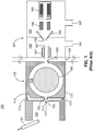
- FIG. 1 schematically depicts a first known system 100 for analyzing ions that includes a FAIMS device 155.
- the general structure and operation of a FAIMS apparatus similar to the FAIMS device 155 shown in FIG. 1 were described by Guevremont and Purves in U.S. Patent No. 6,806,466 .
- Variations in the electrode structure and function were described by Guevremont et al. in U.S. Patent No. 6,713,758 , U.S. Patent No. 7,034,289 and U.S. Patent No. 7,223,967 and by Belford in U.S. Patent No. 7,468,511 .
- a solution of sample to be analyzed is introduced as a spray of liquid droplets into an ionization chamber 105 via atmospheric pressure ion source 110.
- Ionization chamber 105 is maintained at a high pressure relative to the regions downstream in the ion path, typically at or near atmospheric pressure.
- Atmospheric pressure ion source 110 may be configured as an electrospray ionization (ESI) probe, wherein a high DC voltage (either positive or negative) is applied to the capillary or "needle" through which the sample solution flows.
- ESI electrospray ionization
- Other suitable ionization techniques may be utilized in place of ESI, including without limitation such well-known techniques as atmospheric pressure chemical ionization (APCI), heated electrospray ionization (HESI), and thermospray ionization.
- APCI atmospheric pressure chemical ionization
- HESI heated electrospray ionization
- thermospray ionization thermospray ionization
- Ions produced by the ion source enter the FAIMS cell 155 through an aperture 117 in an entrance plate 120 and then through an inlet orifice 150 after passing through an expansion chamber 111.
- the expansion chamber is provided with a gas, typically helium or other inert gas, which is introduced into the expansion chamber 111 via a gas conduit 113.
- a portion of the gas flows back into the ionization chamber 105 through entrance plate aperture 117 in counter-flow to the ions and droplets and serves to desolvate charged droplets.
- Another portion of the gas combines with the analyte ions in chamber 111 and serves as a carrier gas through the FAIMS cell 155.
- the combined ion/carrier gas flow then enters FAIMS cell 155 through inlet orifice 150.
- the carrier gas flow may be carefully metered to maintain flow rates within predetermined limits which will depend on the FAIMS cell size, electrode geometry, and operational considerations.
- An electrical potential difference is maintained between the entrance plate 120 and the FAIMS cell 155 and, thus, physical separation is maintained between these components.
- a non-conducting sealing element 173, such as a gasket or O-ring maintains the FAIMS gas within the apparatus and prevents contamination of this gas from outside air. Because of drawing-space limitations, this sealing element is not explicitly shown in some of the accompanying drawings.
- the FAIMS cell 155 includes inner and outer electrodes 165 and 170 having radially opposed surfaces, which define therebetween an annular separation region 175 (an “analytical gap") through which the ions are transported.
- the FAIMS cell geometry depicted in FIG. 1 may be generally referred to as a "side-to-side FAIMS cell", in which the longitudinal axes (axes of cylindrical surfaces, directed out of the page) of inner electrode 165 and outer electrode 170 are oriented transversely with respect to the overall direction of ion flow.
- the principles of the design and operation of FAIMS cells have been extensively described by Guevremont et al. in U.S. Pat. No.
- the carrier gas and ions flow through the separation region 175 from inlet orifice 150 to exit orifice 185.
- Ion separation is effected within the separation region (analytical gap) 175 of the FAIMS cell 155 by applying an asymmetric waveform having a peak voltage (DV) and a compensation voltage (CV) to one of the inner or outer electrodes, 165, 170.
- the values of CV and DV are set to allow transmission of a selected ion species through separation region 175.
- Other ion species having different relative values of high field and low field mobilities will migrate to the surface of one of the electrodes and be neutralized.
- the selected ions emerge from the FAIMS cell 155 through exit orifice 185 and pass through a small gap 183 separating the FAIMS cell 155 from a mass spectrometer 157.
- ions are electrostatically guided into at least one reduced pressure chamber 188 of the mass spectrometer 157 through an orifice in the mass spectrometer or through an ion transfer tube 163.
- the at least one reduced pressure chamber may be evacuated by a vacuum port 191.
- At least a portion of ion transfer tube 163 may be surrounded by and in good thermal contact with a heat source, such as heater jacket 167.
- the heater jacket 167 which may take the form of a conventional resistance heater, is operable to raise the temperature of ion transfer tube 163 to promote further desolvation of droplets entering the ion transfer tube 163.
- ions are transferred through an orifice 193 of a skimmer 194 into a high vacuum chamber 195 maintained at a low pressure (typically around 100 millitorr) relative to the reduced pressure chamber 188.
- the high vacuum chamber 195 is typically evacuated by turbo or similar high-vacuum pumps via a vacuum port 197.
- the skimmer 194 may be fabricated from an electrically conductive material, and an offset voltage may be applied to skimmer 194 to assist in the transport of ions through interface region and into skimmer orifice 193.
- Ions passing through skimmer orifice 193 may be focused or guided through ion optical assembly 198, which may include various electrodes forming ion lenses, ion guides, ion gates, quadrupole or octopole rod sets, etc.
- the ion optical assembly 198 may serve to transport ions to an analyzer 199 for mass analysis.
- Analyzer 199 may be implemented as any one or a combination of conventional mass analyzers, including (without limitation) a quadrupole mass analyzer, ion trap, or time-of-flight analyzer.
- FIG. 2 shows the results of calculated simulations of ion trajectories of the BCA anion within the FAIMS 155, with the ion-cloud region 127 indicating the region within which most of the ions flow.
- the simulations shown in FIG. 2 which include simulations of ion flow within a flowing gas, indicate that significant ion losses occur at the entrance plate 120 and on a portion of the inner electrode 165 that is exposed to the FAIMS inlet 150.
- Curve 204 of FIG. 3 illustrates the results of a simulated CV scan of the BCA anion through the known FAIMS apparatus of FIG. 2 . This may be compared with curve 202, which presents the results of a second simulation in which ions are hypothetically introduced between the FAIMS electrodes, without encountering the entrance plate.
- the overall transmission of ions from the ion source to the exit orifice is only approximately 10%.
- ions are lost near the FAIMS entrance, few ions are lost inside the analytical gap 175 because, owing to the cylindrical shape of the FAIMS electrode ( FIG. 1 ), ions within the separation region 175 that is away from the inlet orifice 150 experience a non-uniform electric field which causes spatial focusing of ions that are travelling in the gap.
- a High Field Asymmetric Waveform Ion Mobility Spectrometry (FAIMS) apparatus comprising: (a) an expansion chamber receiving ions from an ion source and a gas flow from a gas inlet; (b) an outer electrode having a generally concave inner surface and comprising (i) an ion inlet orifice comprising an orifice wall, an orifice inlet end and an orifice outlet end, the ion inlet orifice operable to receive ions from an ion source and a portion of the gas flow from the expansion chamber and (ii) an ion outlet; and (c) an inner electrode having a generally convex outer surface that is disposed in a spaced-apart and facing arrangement relative to the inner surface of the outer electrode for defining an ion separation region therebetween, wherein the portion of the gas flow and a portion of the ions are received into the ion separation region from the ion inlet and travel through the
- the novel orifice structure applies the principles of the effect, which is the general tendency of a fluid jet to be drawn towards and follow the contour of a curved solid surface.
- the novel orifice structure When used as a gas and ion inlet of a FAIMS outer electrode, the novel orifice structure produces curved streamlines of a carrier gas flow such that the gas stream enters a FAIMS gap with a progressive turn away from the inner electrode so as to flow generally parallel to the inner walls of the outer electrode.
- the orifice is constructed such that the edges of the outer electrode orifice are smoothly curved such that the inner diameter of the orifice increases towards both extremities of the orifice. A gas stream flowing against this curvature will adhere closely to the surface and gradually flow along the curvature. When this curvature is incorporated into the electrode geometry, the gas stream entering the FAIMS will flow gently inside the analyzer gap rather than impact the inner electrode.
- the curvature of the ion inlet orifice wall may comprise different radii of curvature along different cross sections of the ion inlet orifice.
- a portion of the inner electrode may comprise a cylinder such that the gas flow and the portion of the ions travel from the ion inlet to the ion outlet through the ion separation region along two pathways at opposite sides of the cylinder.
- a portion of the orifice wall may protrude into the expansion chamber so as to comprise a ring surrounding the orifice.
- the apparatus may further comprise an entrance plate having an aperture through which the ions are provided to the ion inlet orifice, wherein the gas flow passes through a gap between a flat surface of the entrance plate and the ring.
- the width of the gap is preferably within the range 0.25 mm to 0.75 mm.
- a High Field Asymmetric Waveform Ion Mobility Spectrometry (FAIMS) apparatus comprising: (a) an ion source; (b) an expansion chamber; (c) an outer electrode having a generally concave inner surface and comprising (i) an ion inlet operable to receive ions from the ion source and to receive a gas flow from the expansion chamber and (ii) an ion outlet; and (d) an inner electrode having a generally convex outer surface that is disposed in a spaced-apart and facing arrangement relative to the inner surface of the outer electrode for defining an ion separation region therebetween, wherein the gas flow and a portion of the ions are received into the ion separation region from the ion inlet and travel through the ion separation region from the ion inlet to the ion outlet, and wherein the apparatus is characterized by (e) a first and a second gas inlet providing a first and a second gas flow,
- the above-described dual gas inlet is provided to maintain a pressure balance in a FAIMS apparatus.
- Such a dual gas inlet generates symmetrical flows inside the FAIMS gap as well as in an associated ion source region.
- a new design of electrode assembly is proposed to facilitate a gentle flow of gas around the FAIMS entrance.
- the first and second gas inlets may be disposed at opposite sides of the ion inlet and are directed towards one another within the expansion chamber.
- the apparatus may comprises an orifice through the outer electrode having an orifice wall, an orifice inlet end and an orifice outlet end, wherein the orifice wall is convexly curved between the inlet end and the outlet end.
- a portion of the orifice wall may protrude into the expansion chamber so as to comprise a ring surrounding the orifice.
- the apparatus may further comprise an entrance plate having an aperture through which the ions are provided to such an ion inlet orifice, wherein the gas flow passes through a gap between a flat surface of the entrance plate and the ring.
- a width of the gap is preferably within the range 0.25 mm to 0.75 mm.
- a High Field Asymmetric Waveform Ion Mobility Spectrometry (FAIMS) apparatus comprising: (a) an ion source; (b) at least one gas inlet; (c) an expansion chamber receiving ions from the ion source and a gas flow from the at least one gas inlet; (d) a first electrode having a convexly curved surface; and (e) a second electrode have a concavely curved surface that is disposed in a spaced-apart and facing arrangement relative to the convexly curved surface of the first electrode for defining an ion separation region therebetween, the ion separation region receiving the ions and a portion of the gas flow from the expansion chamber, wherein a deflection of an average ion trajectory upon entering the ion separation region is greater than zero degrees but substantially less then ninety degrees.
- FIG. 4 schematically illustrates an embodiment of a FAIMS apparatus in that represents a first modification of the apparatus shown in FIGS. 1-2 .
- the FAIMS apparatus 101 employs two gas conduits 113a, 113b that simultaneously deliver gas flows to the expansion chamber 111 and that are symmetrically disposed about the inlet orifice 150.
- This symmetric gas introduction within the apparatus 101 eliminates the tendency within the conventional apparatus for a portion of the ions to be pushed, by gas flow from the single conduit 113, towards one side of the apparatus midline.
- the results of the combined electrostatic and fluid dynamic modeling show a symmetrical flow of ions from source to FAIMS inlet with little or no loss on the entrance plate 120. It is here noted that all fluid dynamic computations referenced in this document were performed using COMSOL Multiphysics® engineering simulation software which is commercially available from COMSOL, Inc., 10850 Wilshire Boulevard, Suite 800 Los Angeles, CA 90024 USA. Electric fields and charged particle trajectories were calculated using SIMION® charged particle optics simulation software commercially available from Scientific Instrument Services of 1027 Old York Rd. Ringoes NJ 08551-1054 USA. Combined fluid dynamic and ion trajectory computations were performed by first calculating bulk gas flows using the COMSOL Multiphysics® software and then inputting the results into a collision model within the SIMION® package.
- the FAIMS apparatus 103 illustrated in FIG. 5 represents a further improvement relative to the FAIMS apparatus 101 of FIG. 4 .
- the cylindrical symmetry dictated by the use of an inner electrode 165 comprising a cylinder with circular cross section causes both the carrier gas and the ions of interest to diverge to two different pathways after passing through the ion inlet orifice 150.
- the geometry is such that a non-trivial proportion of ions are neutralized against the inner electrode 165.
- the FAIMS apparatus 103 retains the two gas conduits 113a, 113b as previously described.
- the inventors have determined that performance is improved if the gas conduits deliver gas flow into the expansion chamber 111 with a flow component in the same direction as the flow of ions or, in other words, with the gas conduits delivering gas from the ion source side of the expansion chamber as shown in FIG. 5 .
- the annular channel 186 When a dispersion voltage (DV) and compensation voltage (CV) are applied to at least one of the first and second electrodes 166, 171 of the FAIMS apparatus 103, the annular channel 186 then serves as an analytical gap, as is well-known with regard to the conventional side-to-side FAIMS 155 shown in FIG. 1 as well as with regard to other known FAIMS apparatus designs.
- the FAIMS 103 does not comprise a cylindrical inner electrode and comprises only a single analytical gap 186, the gas and ion flow, as indicated by the ion cloud 125, does not separate into diverging pathways, as occurs for conventional side-to-side FAIMS apparatuses.
- the geometry of the electrode surfaces 11, 13 of the FAIMS apparatus 103 are such that, upon entering the analytical gap 186, the average flow of ions is in a direction that is not directly toward and not perpendicular to either of the surfaces 11, 13 defining the channel 186. Instead, the geometry is such that the inlet orifice 150 into the channel 186 intersects the expansion chamber 111 at an angle such that the average flow direction of ions changes by substantially less than ninety degrees upon their entrance into the channel. This is illustrated in inset 83 of FIG. 5 which shows an enlarged portion of the FAIMS apparatus 103.
- trajectory 85 the average or overall trajectory of ions passing into the expansion chamber 111 towards the two electrodes is shown as trajectory 85, whereas the average ion trajectory upon entering the channel (analytical gap) 185 is shown as trajectory 87.
- the angle of deflection of average ion trajectory is thus greater than zero degrees but substantially less then ninety degrees.
- FIG. 6 provides another schematic cross-sectional view of a dual-gas-inlet FAIMS apparatus 107, somewhat similar to the apparatus previously illustrated in FIG. 4 .
- One difference between the apparatus 107 shown in FIG. 6 and the apparatus 101 shown in FIG. 4 is that, in the FAIMS the apparatus 107, the entry of gas into the expansion chamber 111 from the gas conduits 113a, 113b is directed from the entrance-plate side (or, equivalently, from the ion-source side) of the expansion chamber instead of from the side that is opposite to the entrance plate.
- the gas in the fashion shown in FIG. 6 reduces the degree of gas counter-flow into the ion source region, thus producing greater flow of carrier gas into the analytical gap 175.
- FIG. 6 provides another schematic cross-sectional view of a dual-gas-inlet FAIMS apparatus 107, somewhat similar to the apparatus previously illustrated in FIG. 4 .
- the entry of gas into the expansion chamber 111 from the gas conduits 113a, 113b is directed from the entrance-plate side
- the ion inlet orifice 150 is indicated in FIG. 6 as a simple cylindrical bore hole through the outer electrode 170. This shape of the ion inlet orifice shown in FIG. 6 is similar to its shape in the conventional side-to-side FAIMS apparatus 155 ( FIG. 1 ). The resulting flow profile is high velocity and aligned directly onto the inner electrode 165 where this electrode faces the ion inlet orifice 150. Experimental data also show this phenomenon in the form of a buildup of chemical material on the inner electrode.
- the fluid dynamics calculations graphically illustrated in FIG. 6 also indicate the existence of some degree of recirculation flow within the analytical gap on either side of the ion inlet orifice 150. Such recirculation could possibly cause unwanted neutralization of ions on both inner and outer electrodes.
- FIG. 7 shows the FAIMS gas flow into an electrode set that is modified so as to decrease the volume and rate of gas flow directly onto the inner electrode.
- the FAIMS apparatus 109 that is schematically illustrated in FIG. 7 is identical to the FAIMS apparatus 107 shown in FIG. 6 except with regard to the shape of the ion inlet orifice.
- Inset 300 of FIG. 7 illustrates an enlarged view of the vicinity of the ion inlet orifice 151 of the FAIMS 109. Note that the wall of the ion inlet orifice 151 of the outer electrode as shown in FIG. 7 is slightly enlarged and rounded as compared to the squared off orifice 150 in the conventional electrode set (e.g., FIG. 6 ).
- the walls 301 of the ion inlet orifice 151 of the FAIMS apparatus 109 are convexly curved between the orifice inlet end 302 and the orifice outlet end 303.
- the inner diameter of the ion inlet orifice is at a minimum value within the orifice. Because of the curvature, the inner diameter smoothly increases or flares outward in both directions (i.e., towards the two ends of the orifice) away from the region of minimum diameter.
- the gas flow in the vicinity of the rounded walls of the ion inlet orifice 151 demonstrates the so-called effect, which is the general tendency of a fluid jet to be drawn towards and follow the contour of a curved solid surface.
- the carrier gas flow entering the analytical gap 175 of the FAIMS apparatus 109 is kept closer to the curvature of the entrance orifice than would otherwise be the case.
- This behavior allows for incorporation of the gas stream into the gap and away from the inner electrode as is indicated in FIG. 7 by the smooth divergence of gas flow vectors away from the center electrode 165 and into the analytical gap 175.
- the smooth divergence of the carrier gas away from the center electrode and into the analytical gap 175 is expected to urge ions along similar pathways, thereby reducing the proportion of ions that are lost as a result of collision with the center electrode.
- the smooth divergence also leads to a larger zone of laminar flow within the analytical gap, with reduced recirculation flow near the entrance orifice.
- FIG. 8 shows the results of combined fluid dynamic and ion trajectory modeling, through the FAIMS apparatus 109.
- FIG. 9 shows a comparison between the transmission efficiency of the apparatus having the curved ion inlet orifice 151 and shown in FIG. 8 (curve 212 ) with that of the prior FAIMS apparatus shown in FIGS. 1 and 2 (curve 214 ). It is evident from the shape of the ion cloud 129 in FIG. 8 that the curved orifice design promotes a smoother bifurcation of ion flow prior around the center electrode and into the analytic gap then is indicated for non-curved orifice designs.
- the smoother flow bifurcation appears to have the effect of reducing gas recirculation flow with the analytical gap just after passing through the inlet orifice, thereby significantly reducing ion neutralization at both inner and outer electrodes (for example, compare FIG. 8 with FIG. 1 ).
- the design of the FAIMS apparatus 109 illustrated in FIG. 8 further differs from the design of the known FAIMS apparatus ( FIG. 1 ) through the provision of a wider aperture 117 in the entrance plate 120 as well as through slight widening of the inlet ion orifice 151 (measured at its point of minimum width).
- the width of the entrance plate aperture 117 is approximately 60% greater in the FAIMS 109 and the width of the ion inlet orifice (measured at its minimum diameter) is approximately 26% greater than the respective aperture widths in the known FAIMS apparatus 155 ( FIGS. 1 and 2 ).
- These wider apertures are such as to maintain the width of the ion cloud 129 at its region of passage through the ion inlet orifice of the novel FAIMS 109 ( FIG. 8 ) the same as its width at its region of passage through the ion inlet orifice of the known FAIMS ( FIG. 2 ) in which it nearly completely fills the orifice.
- the calculated approximate 10-fold improvement in transmission is achieved with minimal re-design of the overall apparatus dimensions or shape, relative to the conventional side-to-side FAIMS.
- this simple modification of an existing FAIMS design may be more desirable than using a different form of FAIMS apparatus, such as the apparatus 103 of FIG. 5 .
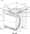
- FIG. 10A illustrates a perspective sectional view (a quarter section view) of another FAIMS apparatus 201 in accordance with the present teachings.
- the illustration in this figure is doubly-cutaway view that is cut away in a plane (the x-z plane) that includes the cylindrical axis 177 of the FAIMS inner electrode 165 and is also cut away in a plane (the y-z plane) that is perpendicular to the cylindrical axis 177.
- Each such sectional plane bisects the overall FAIMS apparatus 201 and, thus, the view shown in FIG. 10A is a quarter-section view.
- FIG. 10B illustrates a cross-section view (both upper and lower diagrams of FIG. 10B ) of the entrance plate and a portion of the outer electrode of the FAIMS apparatus of FIG. 10A .
- FIG. 10B also schematically illustrates (lower diagram only) flow vectors within the gas expansion chamber 111 of the apparatus 201.
- the FAIMS apparatus 201 differs from previously-described apparatus with regard to the configuration of the ion inlet orifice 152, the gas expansion chamber 111 and the relationship between the inlet orifice 152 and the gas expansion chamber 111. As shown, the apparatus 201 also includes a desolvation chamber 115 recessed into the entrance plate 120 and surrounding the entrance plate aperture 117.
- the expansion chamber 111 of the apparatus 201 forms a recess within the entrance plate 120 in a fashion so as to circumferentially surround the ion inlet orifice 152. Further, the expansion chamber recess is provided such that the a portion of the walls of the ion inlet orifice 152 protrude into the expansion chamber 111 so as to form a ring 119 that circumferentially surrounds a portion of the ion inlet orifice 152.
- the space between the entrance plate 120 and the inlet end 302 of the ion inlet orifice comprises a narrow gap 126 between the entrance plate and the inlet end of the ion inlet orifice.
- the entrance plate 120 is configured such that an overlap portion 128 of a face of the entrance plate that bounds the expansion chamber 111 extends beyond the expansion chamber so as to also face the ring portion 119 of the walls of the ion inlet orifice 152.
- gas that enters the expansion chamber 111 through gas conduits 113 is caused to flow around the circumference of the ring 119 and then to flow into and through the gap 126.
- the apparatus 201 is configured such that the width of the gap 126 is significantly less than the width of the expansion chamber 111, wherein the width of the gap is measured between the entrance plate 120 and the inlet end 302 of the ion inlet orifice 152 and the width of the chamber 111 is measured between the facing surfaces of the entrance plate 120 and the outer electrode 170 that bound the chamber. Because of these different widths, the gas pressure and flow velocity are both caused to increase as the gas flows into the gap.
- the increased-velocity gas flow then enters the inlet end 302 of the ion inlet orifice 152 at through the entirety of the gap 126 that circumferentially surrounds the inlet end of the ion inlet orifice 152. Ions pass through the aperture 117 in the entrance plate and then cross the gap 126 and pass into the ion inlet orifice 152 where they are entrained in the gas flow.
- the overlap portion 128 of the entrance plate confines the gas to the gap 126 and enables the increase in flow velocity.
- the increased gas flow velocity produced by the squeezing of the gas flow into the gap 126 causes a high-velocity boundary layer to form against the convexly curved interior walls of the ion inlet orifice 152, thereby causing the high velocity gas to follow the curved surface of the walls in accordance with the effect.
- the high velocity gas flow (and, consequently, the majority of the gas itself) is diverted into the analytical gap 175 so as to avoid impacting the inner electrode 165.
- the majority of the entrained ions are carried along with the gas, thereby improving the ion throughput through the FAIMS apparatus.
- the curvature of the interior walls of the ion inlet orifice 152 of the FAIMS apparatus 201 differs from the curvature of the walls of the inlet oriface 151 of the FAIMS apparatus 109 ( FIGS. 7-8 ) in that the walls of the inlet orifice 152 comprise different radii of curvature in different cross sections.
- the radius of curvature is of the wall is r 1 whereas, in the y-z cross section oriented perpendicular to the axis 177, the radius of curvature is r 2 , where r 2 > r 1 .
- the reason for this difference in the wall curvature in different directions is that, in the y-z plane, the required deflection of the gas jet in the y direction is greater than the amount of deflection that that is either necessary or desirable in the x-direction in the x-z plane.
- the greater degree of deflection required in the y-z plane is a simple result of the geometry of the annular analytical gap 175. For example, consider gas that approaches the ion inlet orifice 152 along the negative -y direction in the expansion chamber 111. In order to be completely diverted into the analytical gap 175, the direction of flow must be diverted so as to have a component vector in the positives y -direction.
- FIG. 11 illustrates a contour plot of calculated gas flow velocities within the annular analytical gap 175 of the FAIMS apparatus 201 of FIG. 10 , shown along the y-z plane. Regions with progressively greater flow velocities are shown with progressively darker shading.
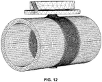
- the calculations were performed using a computational fluid dynamics routing employing the finite element grid pattern shown in FIG. 12 .
- the grid pattern in FIG. 12 is superimposed upon the internal gas volume within the FAIMS apparatus of FIG. 10 . Note that no apparatus elements are shown in FIG. 12 .
- the grid or mesh spacing is not uniform.
- a more closely spaced mesh was used in the region around the curved orifice walls and within the vicinity of the axis that passes from the ion inlet orifice to the ion exit orifice so as to accurately model the gas flow in these regions in which the velocity and flow streamlines change rapidly.
- the average quality of the mesh cells around the curved wall surface was 0.85.
- FAIMS apparatuses are often used in conjunction with mass spectrometers, so as to eliminate interfering background ions from an ion stream prior to mass spectrometry analysis.
- mass spectrometer For practical reasons, there are size limitations to a FAIMS apparatus that is interfaced to a mass spectrometer in such a fashion. From a practical standpoint, the size of the FAIMS apparatus is limited such that the diameter of the inner electrode is limited to approximately 20 mm or less and the width of the analytical gap is limited to approximately 20 mm or less. Accordingly, the fluid dynamic calculations illustrated in the accompanying figures were performed so as to model a FAIMS apparatus within this size range. The fluid dynamics calculations indicate that decreasing the width of the gap 126 ( FIG.
- the gap width is greater than 0.75 mm, then the streamlines diverge and separate from the curved wall surface. However, for practical reasons, the width of the gap is preferably greater than about 0.25 mm. Also, increasing the gas flow rate gives higher throughput, provided that the gas flow does not become turbulent.
- the Reynolds number for flow in the modeled apparatus is approximately 70 for an internal flow rate of 0.5 m/s and is approximately 209 for an internal flow rate of 5.0 m/s, so the flow remains laminar.
- throughput needs to be balanced against FAIMS analytical resolution, which decreases as the flow rate increases.
- FIG. 10 illustrates a FAIMS apparatus comprising both an ion inlet orifice 152 that has curved walls and that protrudes into a gas expansion chamber and also comprising multiple gas inlet conduits 113 providing FAIMS bath gas to the expansion chamber from opposing sides.
- any form of gas inlet could suffice, such as for example, gas inlet "apertures”.
- gas inlet is described herein as an "orifice”, it could equally take the form of or be described as an "aperture” or, in some embodiments, a "conduit”.
Landscapes
- Physics & Mathematics (AREA)
- Chemical & Material Sciences (AREA)
- Spectroscopy & Molecular Physics (AREA)
- Analytical Chemistry (AREA)
- Life Sciences & Earth Sciences (AREA)
- Health & Medical Sciences (AREA)
- Electrochemistry (AREA)
- Chemical Kinetics & Catalysis (AREA)
- Biochemistry (AREA)
- General Health & Medical Sciences (AREA)
- General Physics & Mathematics (AREA)
- Immunology (AREA)
- Pathology (AREA)
- Other Investigation Or Analysis Of Materials By Electrical Means (AREA)
Applications Claiming Priority (4)
| Application Number | Priority Date | Filing Date | Title |
|---|---|---|---|
| US201261648940P | 2012-05-18 | 2012-05-18 | |
| US13/787,574 US8664593B2 (en) | 2012-05-18 | 2013-03-06 | Control of gas flow in high field asymmetric waveform ion mobility spectrometry |
| EP13791430.5A EP2850641B1 (de) | 2012-05-18 | 2013-05-03 | Steuerung eines gasstromes in der hochfeld-ionenmobilitätsspektrometrie mit asymmetrischer wellenform |
| PCT/US2013/039516 WO2013173095A1 (en) | 2012-05-18 | 2013-05-03 | Control of gas flow in high field asymmetric waveform ion mobility spectrometry |
Related Parent Applications (2)
| Application Number | Title | Priority Date | Filing Date |
|---|---|---|---|
| EP13791430.5A Division EP2850641B1 (de) | 2012-05-18 | 2013-05-03 | Steuerung eines gasstromes in der hochfeld-ionenmobilitätsspektrometrie mit asymmetrischer wellenform |
| EP13791430.5A Division-Into EP2850641B1 (de) | 2012-05-18 | 2013-05-03 | Steuerung eines gasstromes in der hochfeld-ionenmobilitätsspektrometrie mit asymmetrischer wellenform |
Publications (1)
| Publication Number | Publication Date |
|---|---|
| EP3671809A1 true EP3671809A1 (de) | 2020-06-24 |
Family
ID=49580551
Family Applications (2)
| Application Number | Title | Priority Date | Filing Date |
|---|---|---|---|
| EP13791430.5A Active EP2850641B1 (de) | 2012-05-18 | 2013-05-03 | Steuerung eines gasstromes in der hochfeld-ionenmobilitätsspektrometrie mit asymmetrischer wellenform |
| EP20150271.3A Withdrawn EP3671809A1 (de) | 2012-05-18 | 2013-05-03 | Steuerung eines gasstroms in der hochfeld-ionenmobilitätsspektrometrie mit asymmetrischer wellenform |
Family Applications Before (1)
| Application Number | Title | Priority Date | Filing Date |
|---|---|---|---|
| EP13791430.5A Active EP2850641B1 (de) | 2012-05-18 | 2013-05-03 | Steuerung eines gasstromes in der hochfeld-ionenmobilitätsspektrometrie mit asymmetrischer wellenform |
Country Status (4)
| Country | Link |
|---|---|
| US (2) | US8664593B2 (de) |
| EP (2) | EP2850641B1 (de) |
| CN (1) | CN104285274B (de) |
| WO (1) | WO2013173095A1 (de) |
Families Citing this family (8)
| Publication number | Priority date | Publication date | Assignee | Title |
|---|---|---|---|---|
| US8952322B2 (en) | 2010-09-20 | 2015-02-10 | Thermo Fisher Scientific (Bremen) Gmbh | FAIMS apparatus and method comprising an ion separation channel of helical shape |
| US8664593B2 (en) * | 2012-05-18 | 2014-03-04 | Thermo Finnigan Llc | Control of gas flow in high field asymmetric waveform ion mobility spectrometry |
| DE102013218930A1 (de) * | 2013-09-20 | 2015-04-16 | Lubrisense Gmbh | Mehrfach-Ölemissionsmessgerät für Motoren |
| EP3270153B1 (de) | 2014-06-13 | 2019-07-24 | Thermo Finnigan LLC | Verfahren zum betrieb eines systems mit einem massenspektrometer, ionenmobilitätsspektrometer und chromatograf |
| GB2586787A (en) * | 2019-08-30 | 2021-03-10 | Shimadzu Corp | Device for performing field asymmetric waveform ion mobility spectrometry |
| CN110828278B (zh) * | 2019-11-15 | 2021-04-20 | 中国科学院大连化学物理研究所 | 一种正负离子同测二维分离离子迁移管 |
| CN112201559A (zh) * | 2020-10-28 | 2021-01-08 | 深圳市斯贝达电子有限公司 | 一种具有聚焦特性平板型高场非对称波形离子迁移谱仪 |
| US20240222105A1 (en) * | 2022-12-29 | 2024-07-04 | Thermo Finnigan Llc | Systems and techniques for in-source ion separation |
Citations (10)
| Publication number | Priority date | Publication date | Assignee | Title |
|---|---|---|---|---|
| US6504149B2 (en) | 1998-08-05 | 2003-01-07 | National Research Council Canada | Apparatus and method for desolvating and focussing ions for introduction into a mass spectrometer |
| US6713758B2 (en) | 1998-08-05 | 2004-03-30 | National Research Council Of Canada | Spherical side-to-side FAIMS |
| US6806466B2 (en) | 2000-03-14 | 2004-10-19 | National Research Council Canada | Parallel plate geometry FAIMS apparatus and method |
| US20050178962A1 (en) * | 2002-02-08 | 2005-08-18 | Ionalytics Corporation | Method and apparatus for desolvating ions for introduction into a faims analyzer region |
| US20060027746A1 (en) * | 2004-08-05 | 2006-02-09 | Ionalytics Corporation | Low field mobility separation of ions using segmented cylindrical FAIMS |
| US7034289B2 (en) | 2002-02-08 | 2006-04-25 | Ionalytics Corporation | Segmented side-to-side FAIMS |
| US7223967B2 (en) | 2002-02-08 | 2007-05-29 | Thermo Finnigan Llc | Side-to-side FAIMS apparatus having an analyzer region with non-uniform spacing and method therefore |
| US7468511B2 (en) | 2006-06-13 | 2008-12-23 | Thermo Finnigan, Llc | FAIMS electrodes with lateral ion focusing |
| US7638765B1 (en) | 2007-07-27 | 2009-12-29 | Thermo Finnigan Llc | FAIMS cell with separate desolvation and carrier gas inlets |
| US7683315B2 (en) | 2007-06-22 | 2010-03-23 | Thermo Finnigan Llc | FAIMS cell having an offset ion inlet orifice |
Family Cites Families (7)
| Publication number | Priority date | Publication date | Assignee | Title |
|---|---|---|---|---|
| US6888128B2 (en) * | 2002-02-15 | 2005-05-03 | Implant Sciences Corporation | Virtual wall gas sampling for an ion mobility spectrometer |
| JP3985058B2 (ja) * | 2003-07-24 | 2007-10-03 | インターソシオシステム株式会社 | イオン分級方法とその装置及びイオン測定装置 |
| US7851745B2 (en) | 2008-12-12 | 2010-12-14 | Thermo Finnigan Llc | Flat plate FAIMS with lateral ion focusing |
| US8049167B2 (en) * | 2009-03-13 | 2011-11-01 | University Of Florida Research Foundation, Inc. | Pneumatic ion beam focusing in high-field asymmetric waveform ion mobility spectrometry (FAIMS) |
| CN101800150B (zh) * | 2010-03-25 | 2011-11-23 | 中国科学院合肥物质科学研究院 | 高场不对称波形离子迁移管及其制作方法 |
| US8158932B2 (en) | 2010-04-16 | 2012-04-17 | Thermo Finnigan Llc | FAIMS having a displaceable electrode for on/off operation |
| US8664593B2 (en) * | 2012-05-18 | 2014-03-04 | Thermo Finnigan Llc | Control of gas flow in high field asymmetric waveform ion mobility spectrometry |
-
2013
- 2013-03-06 US US13/787,574 patent/US8664593B2/en active Active
- 2013-05-03 CN CN201380024847.7A patent/CN104285274B/zh active Active
- 2013-05-03 EP EP13791430.5A patent/EP2850641B1/de active Active
- 2013-05-03 EP EP20150271.3A patent/EP3671809A1/de not_active Withdrawn
- 2013-05-03 WO PCT/US2013/039516 patent/WO2013173095A1/en not_active Ceased
-
2014
- 2014-02-11 US US14/178,137 patent/US8859960B2/en active Active
Patent Citations (11)
| Publication number | Priority date | Publication date | Assignee | Title |
|---|---|---|---|---|
| US6504149B2 (en) | 1998-08-05 | 2003-01-07 | National Research Council Canada | Apparatus and method for desolvating and focussing ions for introduction into a mass spectrometer |
| US6639212B1 (en) | 1998-08-05 | 2003-10-28 | National Research Council Canada | Method for separation of isomers and different conformations of ions in gaseous phase |
| US6713758B2 (en) | 1998-08-05 | 2004-03-30 | National Research Council Of Canada | Spherical side-to-side FAIMS |
| US6806466B2 (en) | 2000-03-14 | 2004-10-19 | National Research Council Canada | Parallel plate geometry FAIMS apparatus and method |
| US20050178962A1 (en) * | 2002-02-08 | 2005-08-18 | Ionalytics Corporation | Method and apparatus for desolvating ions for introduction into a faims analyzer region |
| US7034289B2 (en) | 2002-02-08 | 2006-04-25 | Ionalytics Corporation | Segmented side-to-side FAIMS |
| US7223967B2 (en) | 2002-02-08 | 2007-05-29 | Thermo Finnigan Llc | Side-to-side FAIMS apparatus having an analyzer region with non-uniform spacing and method therefore |
| US20060027746A1 (en) * | 2004-08-05 | 2006-02-09 | Ionalytics Corporation | Low field mobility separation of ions using segmented cylindrical FAIMS |
| US7468511B2 (en) | 2006-06-13 | 2008-12-23 | Thermo Finnigan, Llc | FAIMS electrodes with lateral ion focusing |
| US7683315B2 (en) | 2007-06-22 | 2010-03-23 | Thermo Finnigan Llc | FAIMS cell having an offset ion inlet orifice |
| US7638765B1 (en) | 2007-07-27 | 2009-12-29 | Thermo Finnigan Llc | FAIMS cell with separate desolvation and carrier gas inlets |
Also Published As
| Publication number | Publication date |
|---|---|
| CN104285274A (zh) | 2015-01-14 |
| US8664593B2 (en) | 2014-03-04 |
| EP2850641A1 (de) | 2015-03-25 |
| US8859960B2 (en) | 2014-10-14 |
| US20130306860A1 (en) | 2013-11-21 |
| CN104285274B (zh) | 2016-08-24 |
| EP2850641B1 (de) | 2020-02-12 |
| US20140158904A1 (en) | 2014-06-12 |
| WO2013173095A1 (en) | 2013-11-21 |
| EP2850641A4 (de) | 2016-01-20 |
Similar Documents
| Publication | Publication Date | Title |
|---|---|---|
| US8859960B2 (en) | Method for transmitting ions and carrier gas between mutually facing curved electrodes | |
| US7514673B2 (en) | Ion transport device | |
| US7915580B2 (en) | Electro-dynamic or electro-static lens coupled to a stacked ring ion guide | |
| US7351960B2 (en) | Enhanced ion desolvation for an ion mobility spectrometry device | |
| US8158932B2 (en) | FAIMS having a displaceable electrode for on/off operation | |
| US7781728B2 (en) | Ion transport device and modes of operation thereof | |
| CA2499471C (en) | High field asymmetric waveform ion mobility spectrometer (faims) | |
| US8324565B2 (en) | Ion funnel for mass spectrometry | |
| US7741600B2 (en) | Apparatus and method for providing ions to a mass analyzer | |
| US20090159796A1 (en) | Quadrupole FAIMS Apparatus | |
| CA2667037A1 (en) | Quadrupole faims apparatus | |
| WO2009110025A1 (ja) | 質量分析装置 | |
| US8258470B2 (en) | Radio frequency lens for introducing ions into a quadrupole mass analyzer | |
| US9159543B2 (en) | Ion deflector for a mass spectrometer | |
| US12548750B2 (en) | Axially progressive lens for transporting charged particles |
Legal Events
| Date | Code | Title | Description |
|---|---|---|---|
| PUAI | Public reference made under article 153(3) epc to a published international application that has entered the european phase |
Free format text: ORIGINAL CODE: 0009012 |
|
| STAA | Information on the status of an ep patent application or granted ep patent |
Free format text: STATUS: THE APPLICATION HAS BEEN PUBLISHED |
|
| AC | Divisional application: reference to earlier application |
Ref document number: 2850641 Country of ref document: EP Kind code of ref document: P |
|
| AK | Designated contracting states |
Kind code of ref document: A1 Designated state(s): AL AT BE BG CH CY CZ DE DK EE ES FI FR GB GR HR HU IE IS IT LI LT LU LV MC MK MT NL NO PL PT RO RS SE SI SK SM TR |
|
| STAA | Information on the status of an ep patent application or granted ep patent |
Free format text: STATUS: THE APPLICATION IS DEEMED TO BE WITHDRAWN |
|
| 18D | Application deemed to be withdrawn |
Effective date: 20210112 |