EP3671728A1 - Structure panel with multi-panel structure(s) - Google Patents
Structure panel with multi-panel structure(s) Download PDFInfo
- Publication number
- EP3671728A1 EP3671728A1 EP19216015.8A EP19216015A EP3671728A1 EP 3671728 A1 EP3671728 A1 EP 3671728A1 EP 19216015 A EP19216015 A EP 19216015A EP 3671728 A1 EP3671728 A1 EP 3671728A1
- Authority
- EP
- European Patent Office
- Prior art keywords
- skin
- layer
- rib
- cavities
- panel
- Prior art date
- Legal status (The legal status is an assumption and is not a legal conclusion. Google has not performed a legal analysis and makes no representation as to the accuracy of the status listed.)
- Pending
Links
- 230000002787 reinforcement Effects 0.000 claims description 34
- 239000002131 composite material Substances 0.000 claims description 15
- 239000007787 solid Substances 0.000 claims description 11
- 239000000835 fiber Substances 0.000 claims description 8
- 238000004519 manufacturing process Methods 0.000 claims description 4
- 238000000034 method Methods 0.000 claims description 4
- 230000001419 dependent effect Effects 0.000 claims 1
- 239000000463 material Substances 0.000 description 22
- 230000001413 cellular effect Effects 0.000 description 20
- 238000003491 array Methods 0.000 description 6
- 230000001154 acute effect Effects 0.000 description 5
- 229920000642 polymer Polymers 0.000 description 4
- OKTJSMMVPCPJKN-UHFFFAOYSA-N Carbon Chemical compound [C] OKTJSMMVPCPJKN-UHFFFAOYSA-N 0.000 description 3
- 229920000049 Carbon (fiber) Polymers 0.000 description 3
- 239000000956 alloy Substances 0.000 description 3
- 229910045601 alloy Inorganic materials 0.000 description 3
- 239000004760 aramid Substances 0.000 description 3
- 229920006231 aramid fiber Polymers 0.000 description 3
- 229920003235 aromatic polyamide Polymers 0.000 description 3
- 229910052799 carbon Inorganic materials 0.000 description 3
- 239000004917 carbon fiber Substances 0.000 description 3
- 239000000919 ceramic Substances 0.000 description 3
- 239000011153 ceramic matrix composite Substances 0.000 description 3
- 239000003733 fiber-reinforced composite Substances 0.000 description 3
- 239000011152 fibreglass Substances 0.000 description 3
- 239000011521 glass Substances 0.000 description 3
- 239000002184 metal Substances 0.000 description 3
- 239000011156 metal matrix composite Substances 0.000 description 3
- VNWKTOKETHGBQD-UHFFFAOYSA-N methane Chemical compound C VNWKTOKETHGBQD-UHFFFAOYSA-N 0.000 description 3
- 230000036961 partial effect Effects 0.000 description 3
- -1 etc.) Substances 0.000 description 2
- 230000000737 periodic effect Effects 0.000 description 2
- 230000002441 reversible effect Effects 0.000 description 2
- 239000000654 additive Substances 0.000 description 1
- 230000000996 additive effect Effects 0.000 description 1
- 230000002238 attenuated effect Effects 0.000 description 1
- 230000003247 decreasing effect Effects 0.000 description 1
- 239000011159 matrix material Substances 0.000 description 1
- 239000011148 porous material Substances 0.000 description 1
- 230000002829 reductive effect Effects 0.000 description 1
Images


Classifications
-
- G—PHYSICS
- G10—MUSICAL INSTRUMENTS; ACOUSTICS
- G10K—SOUND-PRODUCING DEVICES; METHODS OR DEVICES FOR PROTECTING AGAINST, OR FOR DAMPING, NOISE OR OTHER ACOUSTIC WAVES IN GENERAL; ACOUSTICS NOT OTHERWISE PROVIDED FOR
- G10K11/00—Methods or devices for transmitting, conducting or directing sound in general; Methods or devices for protecting against, or for damping, noise or other acoustic waves in general
- G10K11/16—Methods or devices for protecting against, or for damping, noise or other acoustic waves in general
- G10K11/172—Methods or devices for protecting against, or for damping, noise or other acoustic waves in general using resonance effects
-
- F—MECHANICAL ENGINEERING; LIGHTING; HEATING; WEAPONS; BLASTING
- F02—COMBUSTION ENGINES; HOT-GAS OR COMBUSTION-PRODUCT ENGINE PLANTS
- F02K—JET-PROPULSION PLANTS
- F02K1/00—Plants characterised by the form or arrangement of the jet pipe or nozzle; Jet pipes or nozzles peculiar thereto
- F02K1/78—Other construction of jet pipes
- F02K1/82—Jet pipe walls, e.g. liners
- F02K1/827—Sound absorbing structures or liners
-
- B—PERFORMING OPERATIONS; TRANSPORTING
- B64—AIRCRAFT; AVIATION; COSMONAUTICS
- B64C—AEROPLANES; HELICOPTERS
- B64C1/00—Fuselages; Constructional features common to fuselages, wings, stabilising surfaces or the like
- B64C1/40—Sound or heat insulation, e.g. using insulation blankets
-
- B—PERFORMING OPERATIONS; TRANSPORTING
- B64—AIRCRAFT; AVIATION; COSMONAUTICS
- B64C—AEROPLANES; HELICOPTERS
- B64C1/00—Fuselages; Constructional features common to fuselages, wings, stabilising surfaces or the like
- B64C1/06—Frames; Stringers; Longerons ; Fuselage sections
- B64C1/12—Construction or attachment of skin panels
-
- F—MECHANICAL ENGINEERING; LIGHTING; HEATING; WEAPONS; BLASTING
- F02—COMBUSTION ENGINES; HOT-GAS OR COMBUSTION-PRODUCT ENGINE PLANTS
- F02C—GAS-TURBINE PLANTS; AIR INTAKES FOR JET-PROPULSION PLANTS; CONTROLLING FUEL SUPPLY IN AIR-BREATHING JET-PROPULSION PLANTS
- F02C7/00—Features, components parts, details or accessories, not provided for in, or of interest apart form groups F02C1/00 - F02C6/00; Air intakes for jet-propulsion plants
- F02C7/24—Heat or noise insulation
-
- G—PHYSICS
- G10—MUSICAL INSTRUMENTS; ACOUSTICS
- G10K—SOUND-PRODUCING DEVICES; METHODS OR DEVICES FOR PROTECTING AGAINST, OR FOR DAMPING, NOISE OR OTHER ACOUSTIC WAVES IN GENERAL; ACOUSTICS NOT OTHERWISE PROVIDED FOR
- G10K11/00—Methods or devices for transmitting, conducting or directing sound in general; Methods or devices for protecting against, or for damping, noise or other acoustic waves in general
- G10K11/16—Methods or devices for protecting against, or for damping, noise or other acoustic waves in general
- G10K11/162—Selection of materials
- G10K11/168—Plural layers of different materials, e.g. sandwiches
-
- F—MECHANICAL ENGINEERING; LIGHTING; HEATING; WEAPONS; BLASTING
- F05—INDEXING SCHEMES RELATING TO ENGINES OR PUMPS IN VARIOUS SUBCLASSES OF CLASSES F01-F04
- F05D—INDEXING SCHEME FOR ASPECTS RELATING TO NON-POSITIVE-DISPLACEMENT MACHINES OR ENGINES, GAS-TURBINES OR JET-PROPULSION PLANTS
- F05D2260/00—Function
- F05D2260/96—Preventing, counteracting or reducing vibration or noise
Definitions
- This disclosure relates generally to structured panels and, more particularly for example, to a structured panel that attenuates sound generated by a gas turbine engine for an aircraft propulsion system.
- Acoustic panels may be used in various applications to attenuate noise.
- An acoustic panel for example, may be configured with a nacelle of an aircraft propulsion system to attenuate noise generated by a gas turbine engine.
- Such an acoustic panel typically includes a honeycomb core connected between a perforated face skin and a solid, non-perforated back skin.
- the honeycomb core includes a plurality of resonating chambers. These resonating chambers are tuned by selecting a desired chamber length and, thus, core thickness that corresponds to a specific target frequency of noise to be attenuated. Increasing the core thickness, for example, will typically tune the resonating chambers for attenuating lower frequency noise. Conversely, decreasing the core thickness will typically tune the resonating chambers for attenuating higher frequency noise.
- a structured panel includes a first skin, a second skin and a core.
- the first skin is configured with or otherwise includes with a plurality of perforations.
- the core forms a plurality of cavities vertically between the first skin and the second skin. Each of the cavities is respectively fluidly coupled with one or more of the perforations.
- the cavities include a first cavity.
- An element of the core is configured with a multi-layered structure.
- the multi-layered structure includes a first layer and a second layer attached to the first layer.
- the first layer is configured with a first rib projecting into the first cavity.
- another structured panel includes a first skin, a second skin and a core.
- the first skin is configured with or otherwise includes with a plurality of perforations.
- the core forms a plurality of cavities vertically between the first skin and the second skin.
- the core includes an array of corrugations that include a first baffle, a second baffle and a first septum.
- the cavities include a first cavity fluidly coupled with one or more of the perforations.
- the first cavity is formed longitudinally between the first baffle and the second baffle.
- the first septum extends from the first baffle to the second baffle.
- the first septum divides the first cavity into fluidly coupled sub-cavities.
- the array of corrugations is configured with a multi-layered structure.
- the multi-layered structure includes a first layer and a second layer bonded to the first layer.
- the first layer is configured with a first structural reinforcement projecting into the first cavity.
- a method for manufacturing a structured panel for attenuating sound.
- a first skin for the panel, a second skin for the panel and a core for the panel are provided.
- the core is bonded to the first skin and the second skin.
- the core forms a plurality of cavities between the first skin and the second skin. Each of the cavities is respectively fluidly coupled with one or more perforations in the first skin.
- the cavities include a first cavity.
- An element of the core is configured with a multi-layered structure.
- the multi-layered structure includes a first layer and a second layer attached to the first layer.
- the first layer is configured with a first structural reinforcement projecting into the first cavity.
- the first structural reinforcement may be configured as or otherwise include a rib.
- the core may include an array of corrugations that include a first baffle, a second baffle and a first septum.
- the first cavity may be formed longitudinally between the first baffle and the second baffle.
- the first septum may extend from the first skin and the first baffle to the second skin and the second baffle. The first septum may divide the first cavity into fluidly coupled sub-cavities.
- the element may be configured as or otherwise include the first baffle.
- the element may be configured as or otherwise include the first septum.
- the element may be configured as or otherwise include the array of corrugations.
- the core may further include a first wall and a second wall.
- the first cavity may be formed laterally between the first wall and the second wall.
- the element may be configured as or otherwise include the first wall.
- the second layer may be configured with a second rib.
- the first rib and the second rib may be disposed on opposing sides of the multi-layered structure.
- the core may include an array of corrugations that include a first baffle, a second baffle and a first septum.
- the first cavity may be formed longitudinally between the first baffle and the second baffle.
- the first septum may extend from the first skin and the first baffle to the second skin and the second baffle.
- the first septum may divide the first cavity into fluidly coupled sub-cavities.
- the first rib may project into a first of the fluidly coupled sub-cavities.
- the second rib may project into a second of the fluidly coupled sub-cavities.
- the cavities may further include a second cavity adjacent the first cavity.
- the second rib may project into the second cavity.
- the first rib may extend along a first trajectory.
- the second rib may extend along a second trajectory that is non-parallel with the first trajectory.
- the first rib may extend along a first trajectory.
- the second rib may extend along a second trajectory that is parallel with the first trajectory.
- the first rib may at least partially (or completely) overlap the second rib.
- the first rib may be configured as a solid first rib.
- the first rib may be configured as a hollow rib.
- the first layer may be further configured with a second rib projecting into the first cavity.
- the core may be configured from or otherwise include composite material.
- the first layer and the second layer each may be configured from or otherwise include a discrete ply of fiber reinforcement.
- the panel may be configured as a panel of a nacelle for an aircraft propulsion system.
- the present disclosure includes structured panels such as, but not limited to, acoustic panels for attenuating sound; e.g., noise.
- Each structured panel may include one or more multi-layered structures with one or more structural reinforcements, such as rib structures, for increasing rigidity, strength, stability (i.e., resistance to buckling) and/or other metrics of structural integrity of that panel.
- structural reinforcements such as rib structures
- the following disclosure will first describe a general panel configuration without structural reinforcements and then describe how one or more multi-layered structures and associated structural reinforcement(s) may be added to one or more elements (e.g., components) of the panel to increase rigidity, strength, stability and/or other metrics of structural integrity of that panel.
- FIG. 1 is a partial, perspective schematic illustration of an acoustic panel 100 for attenuating noise.
- This acoustic panel 100 may be configured to attenuate noise generated by an aircraft propulsion system such as, for example, a turbofan propulsion system or a turbojet propulsion system.
- the acoustic panel 100 may be configured with a nacelle of the propulsion system.
- the acoustic panel 100 may be configured as or with an inner or outer barrel, a translating sleeve of a thrust reverser, a blocker door, etc.
- the acoustic panel 100 may be configured with another component / structure of the aircraft such as its fuselage or a wing.
- the acoustic panel 100 may be configured to also or alternatively attenuate aircraft related noise other than that generated by the propulsion system.
- the acoustic panel 100 of the present disclosure may alternatively be configured for non-aircraft applications.
- the acoustic panel 100 extends longitudinally along an x-axis.
- the acoustic panel 100 extends laterally along a y-axis.
- the acoustic panel 100 extends vertically along a z-axis.
- the term "vertical" is used herein to describe a depthwise panel direction and is not limited to a gravitational up/down direction.
- the x-y plane is shown as a generally flat plane. However, in other embodiments, the x-y plane and, thus, the acoustic panel 100 may be curved and/or follow an undulating geometry.
- the x-y plane and, thus, the acoustic panel 100 may be arcuate, cylindrical or conical with or without radial undulations.
- the vertical direction may change at different locations along the x-y plane; e.g., the vertical direction may be a radial direction for a cylindrical or conical acoustic panel.
- the acoustic panel 100 includes a perforated first (e.g., face) skin 102, a solid non-perforated second (e.g., back) skin 104 and a cellular core 106.
- the cellular core 106 is disposed and extends vertically between the first skin 102 and the second skin 104.
- the cellular core 106 is also connected to the first skin 102 and the second skin 104.
- the cellular core 106 may be fused, adhered, welded, brazed and/or otherwise bonded to the first skin 102 and/or the second skin 104.
- the cellular core 106 may also or alternatively be mechanically fastened to the first skin 102 and/or the second skin 104.
- the cellular core 106 may be formed integral with the first skin 102 and/or the second skin 104 as a monolithic body using, for example, additive manufacturing. However, the present disclosure is not limited to any particular manufacturing methods.
- the first skin 102 may be configured as a relatively thin sheet or layer of material that extends longitudinally and laterally along the x-y plane.
- This first skin material may include, but is not limited to, a polymer, a fiber reinforced composite (e.g., fiberglass composite, carbon fiber composite, aramid fiber composite, composite reinforced by any combination of glass, carbon, aramid or other fibers, etc.), metal, alloys, metal matrix composite, ceramic, or ceramic matrix composite, or a combination thereof.
- the first skin 102 has a vertical thickness 108 that extends vertically between opposing side surfaces 110 and 112.
- the first skin 102 includes a plurality of perforations 114; e.g., apertures such as through-holes (see also FIG.1 ). Each of these perforations 114 extends generally vertically through the first skin 102 between its side surfaces 110 and 112. In other embodiments, the perforations 114 may be non-uniform through the thickness 108 and/or may be non-perpendicular to the side surfaces 110 and/or 112.
- the second skin 104 may be configured as a relatively thin sheet or layer of (e.g., continuous and uninterrupted) material that extends longitudinally and laterally along the x-y plane (see FIG. 1 ).
- This second skin material may include, but is not limited to, a polymer, a fiber reinforced composite (e.g., fiberglass composite, carbon fiber composite, aramid fiber composite, composite reinforced by any combination of glass, carbon, aramid or other fibers, etc.), metal, alloys, metal matrix composite, ceramic, or ceramic matrix composite, or a combination thereof.
- the second skin material may be the same as or different than the first skin material.
- the second skin 104 has a vertical thickness 116 that extends vertically between opposing side surfaces 118 and 120.
- This vertical thickness 116 may be substantially equal to or different (e.g., greater or less) than the vertical thickness 108 of the first skin 102.
- the thickness 108 of the first skin 102 and/or the thickness 116 the second skin 104 may be uniform or non-uniform along the x-y plane.
- the cellular core 106 extends longitudinally and laterally along the x-y plane.
- the cellular core 106 has a vertical thickness 122 that extends vertically between opposing core sides, which sides are respectively abutted against the first skin 102 and the second skin 104 and their side surfaces 112 and 118.
- the vertical thickness 122 may be substantially greater than the vertical thicknesses 108 and 116 of the first skin 102 and/or the second skin 104, respectively.
- the vertical thickness 122 for example, may be at least ten to forty times (10-40x), or more, greater than the vertical thicknesses 108 and 116; however, the acoustic panel 100 of the present disclosure is not limited to such an exemplary embodiment.
- the cellular core 106 includes a plurality of solid non-perforated walls 124 (e.g., cavity sidewalls) and one or more arrays of corrugations 126.
- the walls 124 and corrugations 126 are arranged together to configure the cellular core 106 as an open cavity (e.g., open cell) structure.
- This open cavity structure forms a plurality of cavities 128 (each including divided sub-cavities 128A and 128B) vertically between the first skin 102 and the second skin 104.
- Each of these cavities 128 may be fluidly coupled with one or more respective perforations 114 in the first skin 102 (see FIG. 2 ).
- each of the walls 124 has a length that extends longitudinally along the x-axis.
- Each of the walls 124 has a thickness that extends laterally along the y-axis.
- each of the walls 124 has a height 122 that extends vertically between the first skin 102 and the second skin 104.
- Each of the walls 124 is at least partially (or completely) connected to or otherwise engaged with the first skin 102 and/or the second skin 104.
- Each of the exemplary walls 124 of FIG. 4 is orientated substantially perpendicular to the first skin 102 and the second skin 104; e.g., at a ninety-degree angle to the skins 102 and 104.
- one or more of the walls 124 may be angularly offset from the first skin 102 and/or the second skin 104 by a non-ninety-degree angle; e.g., an acute angle or an obtuse angle.
- the walls 124 are arranged generally parallel with one another; see also FIG. 3 .
- the walls 124 are laterally spaced from one another along the y-axis so as to respectively form the cavities 128 between the walls 124.
- Each of the walls 124 shown in FIG. 4 therefore respectively forms lateral sides of adjacent cavities 128 on either side of the respective wall 124.
- Each of the walls 124 thereby also fluidly separates those cavities 128 on either side of the wall 124.
- each of the corrugations 126 in each array are disposed and extend laterally between a laterally adjacent pair of the walls 124; see also FIG. 4 .
- Each of the corrugations 126 includes a solid non-perforated baffle 130 and a porous (e.g., perforated) septum 132.
- one or more or each of the corrugations 126 includes only porous (e.g. perforated) septa 132, or only solid non-perforated baffles 130 in an alternating periodic or non-periodic pattern along the y-axis or the x-axis or both.
- the baffle 130 has a width extending laterally between opposing lateral sides. These lateral sides are at least partially (or completely) connected to or otherwise engaged with a respective laterally adjacent pair of the walls 124.
- the baffle 130 has a length extending diagonally (e.g., vertically and longitudinally) between opposing top and bottom ends 134 and 136. Note, the terms "top” and “bottom” are used above to describe ends of the baffle 130 as situated in the drawings and are not intended to limit the baffle 130 or the acoustic panel 100 to such an exemplary gravitational orientation.
- the septum 132 has a width extending laterally between opposing lateral sides. These lateral sides are connected to or otherwise engaged with a respective laterally adjacent pair of the walls 124.
- the septum 132 has a length extending diagonally (e.g., vertically and longitudinally) between opposing top and bottom ends 138 and 140. Note, the terms “top” and “bottom” are used above to describe ends of the septum 132 as situated in the drawings and are not intended to limit the septum 132 or the acoustic panel 100 to such an exemplary gravitational orientation.
- the septum 132 includes one or more perforations 142.
- the perforations 142 are configured as through holes.
- the perforations 142 may be formed by interconnected pores in the septum 132 where the septum material, for example, has an open cell porous structure.
- the top end 134 of the baffle 130 is connected at least partially (or completely) to or otherwise engaged with the first skin 102. This top end 134 is also longitudinally connected to the top end 138 of the septum 132 at an interface 144 between the baffle 130 and the septum 132.
- the bottom end 136 of the baffle 130 is connected to or otherwise engaged with the second skin 104. This bottom end 136 is also longitudinally connected to the bottom end 140 of a septum 132 of an adjacent one of the corrugations 126 at an interface 146.
- the baffle 130 extends vertically between the first skin 102 and the second skin 104 and longitudinally between the septums 132.
- the baffle 130 is therefore angularly offset from the first skin 102 and the second skin 104 by an included angle 148; e.g., between 30-60 degrees.
- This angle 148 is an acute angle such as, but not limited to, about forty-five degrees (45°).
- the top end 138 of the septum 132 is at least partially (or completely) connected to or otherwise engaged with the first skin 102. This top end 138 is also longitudinally connected to the top end 134 of the baffle 130 as described above.
- the bottom end 140 of the septum 132 is at least partially (or completely) connected to or otherwise engaged with the second skin 104. This bottom end 140 is also longitudinally connected to the bottom end 136 of a baffle 130 of an adjacent one of the corrugations 126 at an interface; e.g., the interface 146.
- the septum 132 extends vertically between the first skin 102 and the second skin 104 and longitudinally between the baffles 130.
- the septum 132 is therefore angularly offset from the first skin 102 and the second skin 104 by an included angle 150; e.g., between 30-60 degrees.
- This angle 150 may be an acute angle such as, but not limited to, about forty-five degrees (45°).
- the angle 150 may be substantially equal to the angle 148 as shown in FIG. 5 .
- the angle 150 may be different from the angle 148; e.g., a larger or smaller acute angle, or a right angle.
- the angle 150 may be about ninety degrees and the angle 148 may be about forty-five degrees as shown in FIG. 6 .
- the angle 148 may be about ninety degrees and the angle 150 may be about forty-five degrees
- each of the cavities 128 extends longitudinally between and is formed by a longitudinally adjacent pair of the baffles 130.
- Each septum 132 is disposed within and divides a respective one of the cavities 128 into fluidly coupled sub-cavities 128A and 128B. More particularly, the perforations 142 in the septum 132 fluidly couple the sub-cavities 128A and 128B together.
- Each of the cavities 128 forms a resonance chamber 152.
- a length 154 of the resonance chamber 152 extends diagonally (e.g., longitudinally and vertically) between the first skin 102 and the second skin 104 and through a respective one of the septums 132.
- the length 154 of the resonance chamber 152 therefore is longer than the vertical thickness 122 of the cellular core 106. This enables noise attenuation of relatively low frequency noise without increasing the vertical thickness 122 of the cellular core 106 and, thus, a vertical thickness of the acoustic panel 100.
- each resonance chamber 152 may receive noise waves through the perforations 114 in the first skin 102.
- the resonance chamber 152 may reverse the phase of one or more frequencies of those sound waves using known acoustic reflection principles and subsequently direct the reverse phase sound waves out of the acoustic panel 100 through the perforations 114 to destructively interfere with other incoming noise waves.
- the cellular core 106 may be constructed from any suitable material or materials.
- the cellular core 106 may be constructed from a polymer, a fiber reinforced composite (e.g., fiberglass composite, carbon fiber composite, aramid fiber composite, composite reinforced by any combination of glass, carbon, aramid or other fibers), metal, alloys, metal matrix composite, ceramic, or ceramic matrix composite, or a combination thereof.
- One or more of components of the cellular core 106 may be constructed from the same or a like material.
- one or more of the components of the cellular core 106 may be constructed from a different material than one or more of the other components of the cellular core 106.
- the cellular core 106 may be constructed from the same material(s) as the first skin 102 and/or the second skin 104, or a different material or materials.
- one or more elements 156A-B (generally referred to as "156") of the acoustic panel 100 and, more particularly, the cellular core 106 may be configured with a multi-layered structure 158A-B (generally referred to as “158") with one or more structural reinforcements 160A-G (generally referred to as "160").
- These structural reinforcements 160 are provided to increase rigidity, stability, strength and/or structural integrity of the corresponding element(s) 156 as well as the acoustic panel 100 as a whole.
- Examples of the one or more elements 156 include, but are not limited to: (A) one, some or each of the baffles 130; (B) one, some or each of the septums 132; (C) one, some or each of the arrays of corrugations 126; (D) one, some or each of the walls 124; and (E) a combination of any two or more of (A) to (D).
- FIGS. 7 and 8 illustrate a portion of the acoustic panel element 156A configured with the multi-layered structure 158A.
- This multi-layered structure 158A includes a first layer 162A (e.g., ply of material) and a second layer 164A (e.g., ply of material).
- the first layer 162A may be a contoured layer.
- the first layer 162A of FIGS. 7 and 8 is configured with one or more of the structural reinforcements 160A.
- Each structural reinforcement 160A of FIGS. 7 and 8 is configured as a rib 166A.
- Each rib 166A may be a stamped, molded and/or otherwise formed in the first layer 162A to project out from an exterior surface 168 / side of the acoustic panel element 156A / multi-layered structure 158A.
- Each rib 166A extends along a trajectory 170A, where the trajectories 170A of the ribs 166A may be parallel with one another as shown in FIG.
- the trajectories 170A of some of the ribs 166A may be non-parallel.
- the term "trajectory” may describe a centerline that follows along a length of a feature, where that length is greater than other dimensions (e.g., a width and/or a thickness) of the feature.
- Each trajectory 170A of FIG. 7 is straight-line trajectory.
- the trajectory 170A of one or more of the ribs 166A may alternatively be a curved or otherwise convoluted line trajectory.
- the second layer 164A may be a flat or non-contoured layer.
- the second layer 164A of FIGS. 7 and 8 is configured without any structural reinforcements (e.g., ribs). More particularly, this second layer 164A is configured with a flat, planar and/or uninterrupted exterior surface 172, which exterior surface 172 is opposite the exterior surface 168.
- the exterior surface 172 may include a plurality of bends therein.
- each portion of the exterior surface 172 associated with a baffle 130 and/or a septum 132 may be flat, planar and/or uninterrupted as shown, for example, in FIGS. 9A to 11A , FIGS. 9B to 11B , FIGS. 9C to 11C , and FIGS. 12 and 13 -.
- the second layer 164A is bonded and/or otherwise attached to the first layer 162A.
- This attachment may be a direct attachment as shown in FIG. 8 .
- the attachment may be an indirect attachment with, for example, one or more intermediate layers between the first layer 162A and the second layer 164A.
- FIGS. 14-16 illustrate a portion of the acoustic panel element 156B configured with the multi-layered structure 158B.
- This multi-layered structure 158B includes a first layer 162B (e.g., ply of material) and a second layer 164B (e.g., ply of material).
- the first layer 162B may be a contoured layer.
- the first layer 162B of FIGS. 14 and 16 is configured with one or more of the structural reinforcements 160B.
- Each structural reinforcement 160B of FIGS. 14 and 16 is configured as a rib 166B.
- Each rib 166B may be a stamped, molded and/or otherwise formed in the first layer 162B to project out from the exterior surface 168 / side of the acoustic panel element 156B / multi-layered structure 158B.
- Each rib 166B extends along a trajectory 170B, where the trajectories 170B of the ribs 166B may be parallel with one another as shown in FIG. 14 ; however, in other embodiments, the trajectories 170B of some of the ribs 166B may be non-parallel.
- the second layer 164B may also be a contoured layer.
- the second layer 164B of FIGS. 15 and 16 is configured with one or more of the structural reinforcements 160C.
- Each structural reinforcement 160C of FIGS. 15 and 16 is configured as a rib 166C.
- Each rib 166C may be a stamped, molded and/or otherwise formed in the second layer 164B to project out from the exterior surface 172 / side of the acoustic panel element 156B / multi-layered structure 158B.
- Each rib 166C extends along a trajectory 170C, where the trajectories 170C of the ribs 166C may be parallel with one another as shown in FIG.
- the trajectories 170C of some of the ribs 166C may be non-parallel.
- the trajectories 170C of the ribs 166C in the second layer 164B may also be parallel with the trajectories 170B of the ribs 166B in the first layer 162B; however, in other embodiments, the trajectories 170B and 170C of some of the ribs 166B and 166C may be non-parallel as shown, for example, in FIGS. 17 and 18 . As shown in FIG.
- each rib 166C in the second layer 164B may be (e.g., longitudinally, laterally and/or vertically) aligned with a closest one of the ribs 166B in the first layer 162B.
- the rib 166C thereby completely overlaps the rib 166B.
- the rib 166C may partially overlap the rib 166B as shown, for example, in FIGS. 17 and 18 .
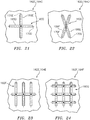
- the rib 166C may not overlap any of the ribs 166B as shown, for example, in FIGS. 19 and 20 .
- the first layer 162B is bonded and/or otherwise attached to the second layer 164B.
- This attachment may be a direct attachment as shown in FIG. 16 .
- the attachment may be an indirect attachment with, for example, one or more intermediate layers between the first layer 162B and the second layer 164B.
- Each structural reinforcement 160 describe above includes a single discrete rib 166A-C (generally referred to as "166"). However, in other embodiments, one or more of the structural reinforcements 160 in the first layer 162C-F and/or in the second layer 164C-F may each include a plurality of ribs as shown, for example, in FIGS. 21-24 .
- the structural reinforcement 160D of FIG. 21 for example, includes a first rib 166D and a second rib 166E. The first rib 166D extends along a first trajectory 170D and the second rib 166E extends along a second trajectory 170E.
- the first trajectory 170D and the second trajectory 170E are straight-line trajectories; however, in other embodiments, one or both of these trajectories 170D and 170E may alternatively be curved or otherwise convoluted line trajectories.
- the first trajectory 170D of the first rib 166D is non-parallel with the second trajectory 170E of the second rib 166E.
- the first trajectory 170D and the first rib 166D of FIG. 21 for example, are perpendicular and coincident with the second trajectory 170E and the second rib 166E.
- an included angle between the first and the second trajectories 170F and 170G and ribs 166F and 166G of the structural reinforcement 160E may be acute (or obtuse) as shown in FIG. 22 for example.
- the first rib 166D intersects and thereby runs into the second rib 166E.
- the first rib 166D of FIG. 21 bisects the second rib 166E and the second rib 166D bisects the first rib 166E.
- Each of the ribs 166A-G (generally referred to as "166") shown in FIGS. 8 , 9A-11A , 9B-11B , 12 , 13 , 14 , 16 and 18 is configured as a hollow rib.
- the rib 166A of FIG. 8 defines an empty channel 174 in an interior side of the first layer 162A such that this channel 174 separates the rib material of the first layer 162A from the adjacent material of the second layer 164A.
- one or more of the ribs 166 described herein may be configured as a solid rib 166H as shown, for example, in FIG. 25 .
- one or more of the ribs 166 described herein may be configured as a perforated rib 166A or non-perforated rib 166B with a solid opposite surface 172 or a perforated opposite surface 176 as shown, for example, in FIGS. 26A, 26B and 26C .
- the channel 174 of FIG. 8 may be alternatively filled with another material to provide a solid rib, which may be perforated or non-perforated.
- each layer 162, 164 of the multi-layered structure 156 may be configured from composite material.
- Each layer 162, 164 may be formed from one or more plies of fiber reinforcement within a polymer matrix.
- the one or more plies of fiber reinforcement within the first layer 162 may be discrete (e.g., not touching and/or formed part of) the one or more plies of fiber reinforcement within the second layer 164.
- each layer 162, 164 may be laid up in a separate step.
- the present disclosure is not limited to the foregoing exemplary materials and/or layup.
- the first layer 162 and the second layer 164 may each partially define one or more of the cavities 128.
- the first layer 162 may partially define one or more of the sub-cavities 128A.
- the first layer ribs 166 project partially into the cavities 128 and, more particularly, the sub-cavities 128A.
- the second layer 164 may partially define one or more of the opposing sub-cavities 128B.
- first and the second layers 162 and 164 may be reversed such that the first layer 162 may partially define one or more of the sub-cavities 128B and the second layer 164 may partially define one or more of the opposing sub-cavities 128A. Accordingly, the first layer ribs 166 will project partially into one or more of the sub-cavities 128B.
Landscapes
- Engineering & Computer Science (AREA)
- Chemical & Material Sciences (AREA)
- Combustion & Propulsion (AREA)
- Mechanical Engineering (AREA)
- General Engineering & Computer Science (AREA)
- Physics & Mathematics (AREA)
- Acoustics & Sound (AREA)
- Multimedia (AREA)
- Aviation & Aerospace Engineering (AREA)
- Soundproofing, Sound Blocking, And Sound Damping (AREA)
Abstract
Description
- This disclosure relates generally to structured panels and, more particularly for example, to a structured panel that attenuates sound generated by a gas turbine engine for an aircraft propulsion system.
- Acoustic panels may be used in various applications to attenuate noise. An acoustic panel, for example, may be configured with a nacelle of an aircraft propulsion system to attenuate noise generated by a gas turbine engine. Such an acoustic panel typically includes a honeycomb core connected between a perforated face skin and a solid, non-perforated back skin. The honeycomb core includes a plurality of resonating chambers. These resonating chambers are tuned by selecting a desired chamber length and, thus, core thickness that corresponds to a specific target frequency of noise to be attenuated. Increasing the core thickness, for example, will typically tune the resonating chambers for attenuating lower frequency noise. Conversely, decreasing the core thickness will typically tune the resonating chambers for attenuating higher frequency noise.
- Recent trends in aircraft engine design such as higher bypass ratios, larger fan diameters, slower rotating fans and/or fewer number of fan blades have resulted in those aircraft engines generating relatively low frequency noise. Relatively strict space constraints for those engines, however, typically limit or prohibit increasing the thickness of an acoustic panel to tune its resonating chambers for such relatively low frequency noise. Reducing the thickness of the acoustic panel also has the concern of compromising structural integrity.
- There is a need in the art for acoustic and structural panels with increased structural integrity and reduced thicknesses.
- According to an aspect of the present disclosure, a structured panel is provided that includes a first skin, a second skin and a core. The first skin is configured with or otherwise includes with a plurality of perforations. The core forms a plurality of cavities vertically between the first skin and the second skin. Each of the cavities is respectively fluidly coupled with one or more of the perforations. The cavities include a first cavity. An element of the core is configured with a multi-layered structure. The multi-layered structure includes a first layer and a second layer attached to the first layer. The first layer is configured with a first rib projecting into the first cavity.
- According to another aspect of the present disclosure, another structured panel is provided that includes a first skin, a second skin and a core. The first skin is configured with or otherwise includes with a plurality of perforations. The core forms a plurality of cavities vertically between the first skin and the second skin. The core includes an array of corrugations that include a first baffle, a second baffle and a first septum. The cavities include a first cavity fluidly coupled with one or more of the perforations. The first cavity is formed longitudinally between the first baffle and the second baffle. The first septum extends from the first baffle to the second baffle. The first septum divides the first cavity into fluidly coupled sub-cavities. The array of corrugations is configured with a multi-layered structure. The multi-layered structure includes a first layer and a second layer bonded to the first layer. The first layer is configured with a first structural reinforcement projecting into the first cavity.
- According to still another aspect of the present disclosure, a method is provided for manufacturing a structured panel for attenuating sound. During this method, a first skin for the panel, a second skin for the panel and a core for the panel are provided. The core is bonded to the first skin and the second skin. The core forms a plurality of cavities between the first skin and the second skin. Each of the cavities is respectively fluidly coupled with one or more perforations in the first skin. The cavities include a first cavity. An element of the core is configured with a multi-layered structure. The multi-layered structure includes a first layer and a second layer attached to the first layer. The first layer is configured with a first structural reinforcement projecting into the first cavity.
- The first structural reinforcement may be configured as or otherwise include a rib.
- The core may include an array of corrugations that include a first baffle, a second baffle and a first septum. The first cavity may be formed longitudinally between the first baffle and the second baffle. The first septum may extend from the first skin and the first baffle to the second skin and the second baffle. The first septum may divide the first cavity into fluidly coupled sub-cavities.
- The element may be configured as or otherwise include the first baffle.
- The element may be configured as or otherwise include the first septum.
- The element may be configured as or otherwise include the array of corrugations.
- The core may further include a first wall and a second wall. The first cavity may be formed laterally between the first wall and the second wall. The element may be configured as or otherwise include the first wall.
- The second layer may be configured with a second rib. The first rib and the second rib may be disposed on opposing sides of the multi-layered structure.
- The core may include an array of corrugations that include a first baffle, a second baffle and a first septum. The first cavity may be formed longitudinally between the first baffle and the second baffle. The first septum may extend from the first skin and the first baffle to the second skin and the second baffle. The first septum may divide the first cavity into fluidly coupled sub-cavities. The first rib may project into a first of the fluidly coupled sub-cavities. The second rib may project into a second of the fluidly coupled sub-cavities.
- The cavities may further include a second cavity adjacent the first cavity. The second rib may project into the second cavity.
- The first rib may extend along a first trajectory. The second rib may extend along a second trajectory that is non-parallel with the first trajectory.
- The first rib may extend along a first trajectory. The second rib may extend along a second trajectory that is parallel with the first trajectory.
- The first rib may at least partially (or completely) overlap the second rib.
- The first rib may be configured as a solid first rib. Alternatively, the first rib may be configured as a hollow rib.
- The first layer may be further configured with a second rib projecting into the first cavity.
- The core may be configured from or otherwise include composite material. The first layer and the second layer each may be configured from or otherwise include a discrete ply of fiber reinforcement.
- The panel may be configured as a panel of a nacelle for an aircraft propulsion system.
- The foregoing features and the operation of the invention will become more apparent in light of the following description and the accompanying drawings.
-
-
FIG. 1 is a partial, perspective schematic illustration of an acoustic panel, in accordance with various embodiments; -
FIG. 2 is a first side sectional illustration of a portion of the acoustic panel, in accordance with various embodiments; -
FIG. 3 is a perspective illustration of a cellular core of the acoustic panel portion, in accordance with various embodiments; -
FIG. 4 is a second side sectional illustration of the acoustic panel portion, in accordance with various embodiments; -
FIG. 5 is a partial enlarged view of the acoustic panel portion ofFIG. 2 , in accordance with various embodiments; -
FIG. 6 is a first side sectional illustration of a portion of another acoustic panel, in accordance with various embodiments; -
FIG. 7 is an illustration of a portion of a multi-layered structure configured with a plurality of structural reinforcements, in accordance with various embodiments; -
FIG. 8 is a side sectional illustration of the multi-layered structure portion ofFIG. 7 , in accordance with various embodiments; -
FIGS. 9A to 9C are side sectional illustrations of the multi-layered structure ofFIG. 7 configured in various exemplary arrays of corrugations, in accordance with various embodiments; -
FIGS. 10A to 10C are side sectional illustrations of the multi-layered structure ofFIG. 7 configured in other various exemplary arrays of corrugations, in accordance with various embodiments; -
FIGS. 11A to 11C are side sectional illustrations of the multi-layered structure ofFIG. 7 configured in still other various exemplary arrays of corrugations, in accordance with various embodiments; -
FIG. 12 is a side sectional illustration of the multi-layered structure ofFIG. 7 configured in still another array of corrugations, in accordance with various embodiments; -
FIG. 13 is a side sectional illustration of the multi-layered structure ofFIG. 7 configured in still another array of corrugations, in accordance with various embodiments; -
FIG. 14 is an illustration of a first side of a portion of a multi-layered structure configured with a plurality of structural reinforcements, in accordance with various embodiments; -
FIG. 15 is an illustration of a second side of the multi-layered structure portion ofFIG. 14 , in accordance with various embodiments; -
FIG. 16 is a side sectional illustration of the multi-layered structure portion ofFIGS. 14 and 15 , in accordance with various embodiments; -
FIG. 17 is an illustration of a portion of a multi-layered structure configured with a plurality of structural reinforcements, in accordance with various embodiments; -
FIG. 18 is a side sectional illustration of the multi-layered structure portion ofFIG. 17 , in accordance with various embodiments; -
FIG. 19 is an illustration of a portion of a multi-layered structure configured with a plurality of structural reinforcements, in accordance with various embodiments; -
FIG. 20 is a side sectional illustration of the multi-layered structure portion ofFIG. 19 , in accordance with various embodiments; -
FIG. 21 is an illustration of a portion of a multi-layered structure configured with another structural reinforcement, in accordance with various embodiments; -
FIG. 22 is an illustration of a portion of a multi-layered structure configured with another structural reinforcement, in accordance with various embodiments; -
FIG. 23 is an illustration of a portion of a multi-layered structure configured with another structural reinforcement, in accordance with various embodiments; -
FIG. 24 is an illustration of a portion of a multi-layered structure configured with still another structural reinforcement, in accordance with various embodiments; and -
FIG. 25 is an illustration of a portion of a multi-layered structure configured with a solid rib, in accordance with various embodiments. -
FIGS. 26A to 26C are illustrations of other various exemplary portions of a multi-layered structure configured with a perforated or non-perforated rib and/or a perforated or non-perforated exterior surface, in accordance with various embodiments. - The present disclosure includes structured panels such as, but not limited to, acoustic panels for attenuating sound; e.g., noise. Each structured panel may include one or more multi-layered structures with one or more structural reinforcements, such as rib structures, for increasing rigidity, strength, stability (i.e., resistance to buckling) and/or other metrics of structural integrity of that panel. For ease of description, the following disclosure will first describe a general panel configuration without structural reinforcements and then describe how one or more multi-layered structures and associated structural reinforcement(s) may be added to one or more elements (e.g., components) of the panel to increase rigidity, strength, stability and/or other metrics of structural integrity of that panel.
-
FIG. 1 is a partial, perspective schematic illustration of anacoustic panel 100 for attenuating noise. Thisacoustic panel 100 may be configured to attenuate noise generated by an aircraft propulsion system such as, for example, a turbofan propulsion system or a turbojet propulsion system. With such a configuration, theacoustic panel 100 may be configured with a nacelle of the propulsion system. Theacoustic panel 100, for example, may be configured as or with an inner or outer barrel, a translating sleeve of a thrust reverser, a blocker door, etc. Alternatively, theacoustic panel 100 may be configured with another component / structure of the aircraft such as its fuselage or a wing. Furthermore, theacoustic panel 100 may be configured to also or alternatively attenuate aircraft related noise other than that generated by the propulsion system. Theacoustic panel 100 of the present disclosure, however, may alternatively be configured for non-aircraft applications. - The
acoustic panel 100 extends longitudinally along an x-axis. Theacoustic panel 100 extends laterally along a y-axis. Theacoustic panel 100 extends vertically along a z-axis. The term "vertical" is used herein to describe a depthwise panel direction and is not limited to a gravitational up/down direction. Furthermore, for ease of illustration, the x-y plane is shown as a generally flat plane. However, in other embodiments, the x-y plane and, thus, theacoustic panel 100 may be curved and/or follow an undulating geometry. For example, the x-y plane and, thus, theacoustic panel 100 may be arcuate, cylindrical or conical with or without radial undulations. Thus, the vertical direction may change at different locations along the x-y plane; e.g., the vertical direction may be a radial direction for a cylindrical or conical acoustic panel. - The
acoustic panel 100 includes a perforated first (e.g., face)skin 102, a solid non-perforated second (e.g., back)skin 104 and acellular core 106. Briefly, thecellular core 106 is disposed and extends vertically between thefirst skin 102 and thesecond skin 104. Thecellular core 106 is also connected to thefirst skin 102 and thesecond skin 104. Thecellular core 106, for example, may be fused, adhered, welded, brazed and/or otherwise bonded to thefirst skin 102 and/or thesecond skin 104. Thecellular core 106 may also or alternatively be mechanically fastened to thefirst skin 102 and/or thesecond skin 104. Alternatively, thecellular core 106 may be formed integral with thefirst skin 102 and/or thesecond skin 104 as a monolithic body using, for example, additive manufacturing. However, the present disclosure is not limited to any particular manufacturing methods. - The
first skin 102 may be configured as a relatively thin sheet or layer of material that extends longitudinally and laterally along the x-y plane. This first skin material may include, but is not limited to, a polymer, a fiber reinforced composite (e.g., fiberglass composite, carbon fiber composite, aramid fiber composite, composite reinforced by any combination of glass, carbon, aramid or other fibers, etc.), metal, alloys, metal matrix composite, ceramic, or ceramic matrix composite, or a combination thereof. Referring now toFIG. 2 , thefirst skin 102 has avertical thickness 108 that extends vertically between opposing side surfaces 110 and 112. Thefirst skin 102 includes a plurality ofperforations 114; e.g., apertures such as through-holes (see alsoFIG.1 ). Each of theseperforations 114 extends generally vertically through thefirst skin 102 between itsside surfaces perforations 114 may be non-uniform through thethickness 108 and/or may be non-perpendicular to the side surfaces 110 and/or 112. - The
second skin 104 may be configured as a relatively thin sheet or layer of (e.g., continuous and uninterrupted) material that extends longitudinally and laterally along the x-y plane (seeFIG. 1 ). This second skin material may include, but is not limited to, a polymer, a fiber reinforced composite (e.g., fiberglass composite, carbon fiber composite, aramid fiber composite, composite reinforced by any combination of glass, carbon, aramid or other fibers, etc.), metal, alloys, metal matrix composite, ceramic, or ceramic matrix composite, or a combination thereof. The second skin material may be the same as or different than the first skin material. Thesecond skin 104 has avertical thickness 116 that extends vertically between opposing side surfaces 118 and 120. Thisvertical thickness 116 may be substantially equal to or different (e.g., greater or less) than thevertical thickness 108 of thefirst skin 102. Thethickness 108 of thefirst skin 102 and/or thethickness 116 thesecond skin 104 may be uniform or non-uniform along the x-y plane. - Referring to
FIG. 3 , thecellular core 106 extends longitudinally and laterally along the x-y plane. Referring again toFIG. 2 , thecellular core 106 has avertical thickness 122 that extends vertically between opposing core sides, which sides are respectively abutted against thefirst skin 102 and thesecond skin 104 and theirside surfaces vertical thickness 122 may be substantially greater than thevertical thicknesses first skin 102 and/or thesecond skin 104, respectively. Thevertical thickness 122, for example, may be at least ten to forty times (10-40x), or more, greater than thevertical thicknesses acoustic panel 100 of the present disclosure is not limited to such an exemplary embodiment. - Referring to
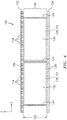
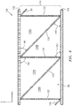
FIGS. 2-4 , thecellular core 106 includes a plurality of solid non-perforated walls 124 (e.g., cavity sidewalls) and one or more arrays ofcorrugations 126. Thewalls 124 andcorrugations 126 are arranged together to configure thecellular core 106 as an open cavity (e.g., open cell) structure. This open cavity structure forms a plurality of cavities 128 (each including divided sub-cavities 128A and 128B) vertically between thefirst skin 102 and thesecond skin 104. Each of thesecavities 128 may be fluidly coupled with one or morerespective perforations 114 in the first skin 102 (seeFIG. 2 ). - Referring to
FIG. 3 , each of thewalls 124 has a length that extends longitudinally along the x-axis. Each of thewalls 124 has a thickness that extends laterally along the y-axis. Referring now toFIG. 4 , each of thewalls 124 has aheight 122 that extends vertically between thefirst skin 102 and thesecond skin 104. - Each of the
walls 124 is at least partially (or completely) connected to or otherwise engaged with thefirst skin 102 and/or thesecond skin 104. Each of theexemplary walls 124 ofFIG. 4 is orientated substantially perpendicular to thefirst skin 102 and thesecond skin 104; e.g., at a ninety-degree angle to theskins walls 124 may be angularly offset from thefirst skin 102 and/or thesecond skin 104 by a non-ninety-degree angle; e.g., an acute angle or an obtuse angle. - The
walls 124 are arranged generally parallel with one another; see alsoFIG. 3 . Thewalls 124 are laterally spaced from one another along the y-axis so as to respectively form thecavities 128 between thewalls 124. Each of thewalls 124 shown inFIG. 4 therefore respectively forms lateral sides ofadjacent cavities 128 on either side of therespective wall 124. Each of thewalls 124 thereby also fluidly separates thosecavities 128 on either side of thewall 124. - Referring to
FIG. 3 , thecorrugations 126 in each array are disposed and extend laterally between a laterally adjacent pair of thewalls 124; see alsoFIG. 4 . Each of thecorrugations 126 includes a solidnon-perforated baffle 130 and a porous (e.g., perforated)septum 132. In another exemplary embodiment, one or more or each of thecorrugations 126 includes only porous (e.g. perforated)septa 132, or only solidnon-perforated baffles 130 in an alternating periodic or non-periodic pattern along the y-axis or the x-axis or both. - Referring to
FIGS. 4 and5 , thebaffle 130 has a width extending laterally between opposing lateral sides. These lateral sides are at least partially (or completely) connected to or otherwise engaged with a respective laterally adjacent pair of thewalls 124. Referring toFIG. 5 , thebaffle 130 has a length extending diagonally (e.g., vertically and longitudinally) between opposing top and bottom ends 134 and 136. Note, the terms "top" and "bottom" are used above to describe ends of thebaffle 130 as situated in the drawings and are not intended to limit thebaffle 130 or theacoustic panel 100 to such an exemplary gravitational orientation. - The
septum 132 has a width extending laterally between opposing lateral sides. These lateral sides are connected to or otherwise engaged with a respective laterally adjacent pair of thewalls 124. Theseptum 132 has a length extending diagonally (e.g., vertically and longitudinally) between opposing top and bottom ends 138 and 140. Note, the terms "top" and "bottom" are used above to describe ends of theseptum 132 as situated in the drawings and are not intended to limit theseptum 132 or theacoustic panel 100 to such an exemplary gravitational orientation. - The
septum 132 includes one ormore perforations 142. In the exemplary embodiment ofFIG. 5 , theperforations 142 are configured as through holes. However, in other embodiments, theperforations 142 may be formed by interconnected pores in theseptum 132 where the septum material, for example, has an open cell porous structure. - The
top end 134 of thebaffle 130 is connected at least partially (or completely) to or otherwise engaged with thefirst skin 102. Thistop end 134 is also longitudinally connected to the top end 138 of theseptum 132 at aninterface 144 between thebaffle 130 and theseptum 132. Thebottom end 136 of thebaffle 130 is connected to or otherwise engaged with thesecond skin 104. Thisbottom end 136 is also longitudinally connected to the bottom end 140 of aseptum 132 of an adjacent one of thecorrugations 126 at aninterface 146. With the foregoing configuration, thebaffle 130 extends vertically between thefirst skin 102 and thesecond skin 104 and longitudinally between theseptums 132. Thebaffle 130 is therefore angularly offset from thefirst skin 102 and thesecond skin 104 by an includedangle 148; e.g., between 30-60 degrees. Thisangle 148 is an acute angle such as, but not limited to, about forty-five degrees (45°). - The top end 138 of the
septum 132 is at least partially (or completely) connected to or otherwise engaged with thefirst skin 102. This top end 138 is also longitudinally connected to thetop end 134 of thebaffle 130 as described above. The bottom end 140 of theseptum 132 is at least partially (or completely) connected to or otherwise engaged with thesecond skin 104. This bottom end 140 is also longitudinally connected to thebottom end 136 of abaffle 130 of an adjacent one of thecorrugations 126 at an interface; e.g., theinterface 146. With the foregoing configuration, theseptum 132 extends vertically between thefirst skin 102 and thesecond skin 104 and longitudinally between thebaffles 130. Theseptum 132 is therefore angularly offset from thefirst skin 102 and thesecond skin 104 by an includedangle 150; e.g., between 30-60 degrees. Thisangle 150 may be an acute angle such as, but not limited to, about forty-five degrees (45°). Theangle 150 may be substantially equal to theangle 148 as shown inFIG. 5 . Alternatively, theangle 150 may be different from theangle 148; e.g., a larger or smaller acute angle, or a right angle. For example, theangle 150 may be about ninety degrees and theangle 148 may be about forty-five degrees as shown inFIG. 6 . In another example theangle 148 may be about ninety degrees and theangle 150 may be about forty-five degrees - Referring to
FIG. 2 , each of thecavities 128 extends longitudinally between and is formed by a longitudinally adjacent pair of thebaffles 130. Eachseptum 132 is disposed within and divides a respective one of thecavities 128 into fluidly coupled sub-cavities 128A and 128B. More particularly, theperforations 142 in theseptum 132 fluidly couple the sub-cavities 128A and 128B together. - Each of the
cavities 128 forms a resonance chamber 152. Alength 154 of the resonance chamber 152 extends diagonally (e.g., longitudinally and vertically) between thefirst skin 102 and thesecond skin 104 and through a respective one of theseptums 132. Thelength 154 of the resonance chamber 152 therefore is longer than thevertical thickness 122 of thecellular core 106. This enables noise attenuation of relatively low frequency noise without increasing thevertical thickness 122 of thecellular core 106 and, thus, a vertical thickness of theacoustic panel 100. For example, each resonance chamber 152 may receive noise waves through theperforations 114 in thefirst skin 102. The resonance chamber 152 may reverse the phase of one or more frequencies of those sound waves using known acoustic reflection principles and subsequently direct the reverse phase sound waves out of theacoustic panel 100 through theperforations 114 to destructively interfere with other incoming noise waves. - The
cellular core 106 may be constructed from any suitable material or materials. Thecellular core 106, for example, may be constructed from a polymer, a fiber reinforced composite (e.g., fiberglass composite, carbon fiber composite, aramid fiber composite, composite reinforced by any combination of glass, carbon, aramid or other fibers), metal, alloys, metal matrix composite, ceramic, or ceramic matrix composite, or a combination thereof. One or more of components of thecellular core 106 may be constructed from the same or a like material. Alternatively, one or more of the components of thecellular core 106 may be constructed from a different material than one or more of the other components of thecellular core 106. Furthermore, thecellular core 106 may be constructed from the same material(s) as thefirst skin 102 and/or thesecond skin 104, or a different material or materials. - Referring to
FIGS. 7 to 26C , one ormore elements 156A-B (generally referred to as "156") of theacoustic panel 100 and, more particularly, thecellular core 106 may be configured with amulti-layered structure 158A-B (generally referred to as "158") with one or morestructural reinforcements 160A-G (generally referred to as "160"). These structural reinforcements 160 are provided to increase rigidity, stability, strength and/or structural integrity of the corresponding element(s) 156 as well as theacoustic panel 100 as a whole. Examples of the one or more elements 156 include, but are not limited to: (A) one, some or each of thebaffles 130; (B) one, some or each of theseptums 132; (C) one, some or each of the arrays ofcorrugations 126; (D) one, some or each of thewalls 124; and (E) a combination of any two or more of (A) to (D). -
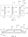
FIGS. 7 and 8 illustrate a portion of theacoustic panel element 156A configured with themulti-layered structure 158A. Thismulti-layered structure 158A includes afirst layer 162A (e.g., ply of material) and asecond layer 164A (e.g., ply of material). - The
first layer 162A may be a contoured layer. Thefirst layer 162A ofFIGS. 7 and 8 , for example, is configured with one or more of thestructural reinforcements 160A. Eachstructural reinforcement 160A ofFIGS. 7 and 8 is configured as arib 166A. Eachrib 166A may be a stamped, molded and/or otherwise formed in thefirst layer 162A to project out from anexterior surface 168 / side of theacoustic panel element 156A /multi-layered structure 158A. Eachrib 166A extends along atrajectory 170A, where thetrajectories 170A of theribs 166A may be parallel with one another as shown inFIG. 7 ; however, in other embodiments, thetrajectories 170A of some of theribs 166A may be non-parallel. Note, the term "trajectory" may describe a centerline that follows along a length of a feature, where that length is greater than other dimensions (e.g., a width and/or a thickness) of the feature. Eachtrajectory 170A ofFIG. 7 is straight-line trajectory. However, in other embodiments, thetrajectory 170A of one or more of theribs 166A may alternatively be a curved or otherwise convoluted line trajectory. - The
second layer 164A may be a flat or non-contoured layer. Thesecond layer 164A ofFIGS. 7 and 8 , for example, is configured without any structural reinforcements (e.g., ribs). More particularly, thissecond layer 164A is configured with a flat, planar and/or uninterruptedexterior surface 172, whichexterior surface 172 is opposite theexterior surface 168. Of course, where theacoustic panel element 156A is configured as one of the arrays ofcorrugations 126, theexterior surface 172 may include a plurality of bends therein. However, each portion of theexterior surface 172 associated with abaffle 130 and/or aseptum 132 may be flat, planar and/or uninterrupted as shown, for example, inFIGS. 9A to 11A ,FIGS. 9B to 11B ,FIGS. 9C to 11C , andFIGS. 12 and 13 -. - Referring again to
FIGS. 7 and 8 , thesecond layer 164A is bonded and/or otherwise attached to thefirst layer 162A. This attachment may be a direct attachment as shown inFIG. 8 . Alternatively, the attachment may be an indirect attachment with, for example, one or more intermediate layers between thefirst layer 162A and thesecond layer 164A. -
FIGS. 14-16 illustrate a portion of theacoustic panel element 156B configured with themulti-layered structure 158B. Thismulti-layered structure 158B includes afirst layer 162B (e.g., ply of material) and asecond layer 164B (e.g., ply of material). - The
first layer 162B may be a contoured layer. Thefirst layer 162B ofFIGS. 14 and 16 , for example, is configured with one or more of thestructural reinforcements 160B. Eachstructural reinforcement 160B ofFIGS. 14 and 16 is configured as arib 166B. Eachrib 166B may be a stamped, molded and/or otherwise formed in thefirst layer 162B to project out from theexterior surface 168 / side of theacoustic panel element 156B /multi-layered structure 158B. Eachrib 166B extends along atrajectory 170B, where thetrajectories 170B of theribs 166B may be parallel with one another as shown inFIG. 14 ; however, in other embodiments, thetrajectories 170B of some of theribs 166B may be non-parallel. - The
second layer 164B may also be a contoured layer. Thesecond layer 164B ofFIGS. 15 and 16 , for example, is configured with one or more of thestructural reinforcements 160C. Eachstructural reinforcement 160C ofFIGS. 15 and 16 is configured as arib 166C. Eachrib 166C may be a stamped, molded and/or otherwise formed in thesecond layer 164B to project out from theexterior surface 172 / side of theacoustic panel element 156B /multi-layered structure 158B. Eachrib 166C extends along atrajectory 170C, where thetrajectories 170C of theribs 166C may be parallel with one another as shown inFIG. 15 ; however, in other embodiments, thetrajectories 170C of some of theribs 166C may be non-parallel. Thetrajectories 170C of theribs 166C in thesecond layer 164B may also be parallel with thetrajectories 170B of theribs 166B in thefirst layer 162B; however, in other embodiments, thetrajectories ribs FIGS. 17 and 18 . As shown inFIG. 16 , eachrib 166C in thesecond layer 164B may be (e.g., longitudinally, laterally and/or vertically) aligned with a closest one of theribs 166B in thefirst layer 162B. Therib 166C thereby completely overlaps therib 166B. However, in other embodiments, therib 166C may partially overlap therib 166B as shown, for example, inFIGS. 17 and 18 . In still other embodiments, therib 166C may not overlap any of theribs 166B as shown, for example, inFIGS. 19 and 20 . - Referring again to
FIGS. 14-16 , thefirst layer 162B is bonded and/or otherwise attached to thesecond layer 164B. This attachment may be a direct attachment as shown inFIG. 16 . Alternatively, the attachment may be an indirect attachment with, for example, one or more intermediate layers between thefirst layer 162B and thesecond layer 164B. - Each structural reinforcement 160 describe above includes a single
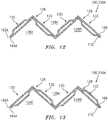
discrete rib 166A-C (generally referred to as "166"). However, in other embodiments, one or more of the structural reinforcements 160 in thefirst layer 162C-F and/or in thesecond layer 164C-F may each include a plurality of ribs as shown, for example, inFIGS. 21-24 . Thestructural reinforcement 160D ofFIG. 21 , for example, includes afirst rib 166D and asecond rib 166E. Thefirst rib 166D extends along afirst trajectory 170D and thesecond rib 166E extends along asecond trajectory 170E. Thefirst trajectory 170D and thesecond trajectory 170E are straight-line trajectories; however, in other embodiments, one or both of thesetrajectories first trajectory 170D of thefirst rib 166D is non-parallel with thesecond trajectory 170E of thesecond rib 166E. Thefirst trajectory 170D and thefirst rib 166D ofFIG. 21 , for example, are perpendicular and coincident with thesecond trajectory 170E and thesecond rib 166E. Of course, in other embodiments, an included angle between the first and thesecond trajectories ribs structural reinforcement 160E may be acute (or obtuse) as shown inFIG. 22 for example. Referring again toFIG. 21 , thefirst rib 166D intersects and thereby runs into thesecond rib 166E. Thefirst rib 166D ofFIG. 21 , for example, bisects thesecond rib 166E and thesecond rib 166D bisects thefirst rib 166E. - Each of the
ribs 166A-G (generally referred to as "166") shown inFIGS. 8 ,9A-11A ,9B-11B ,12 ,13 ,14 ,16 and18 is configured as a hollow rib. Therib 166A ofFIG. 8 , for example, defines anempty channel 174 in an interior side of thefirst layer 162A such that thischannel 174 separates the rib material of thefirst layer 162A from the adjacent material of thesecond layer 164A. However, in other embodiments, one or more of the ribs 166 described herein may be configured as asolid rib 166H as shown, for example, inFIG. 25 . In yet further embodiments, one or more of the ribs 166 described herein may be configured as aperforated rib 166A ornon-perforated rib 166B with a solidopposite surface 172 or a perforatedopposite surface 176 as shown, for example, inFIGS. 26A, 26B and 26C . In still other embodiments, thechannel 174 ofFIG. 8 may be alternatively filled with another material to provide a solid rib, which may be perforated or non-perforated. - In some embodiments, each layer 162, 164 of the multi-layered structure 156 may be configured from composite material. Each layer 162, 164, for example, may be formed from one or more plies of fiber reinforcement within a polymer matrix. The one or more plies of fiber reinforcement within the first layer 162 may be discrete (e.g., not touching and/or formed part of) the one or more plies of fiber reinforcement within the second layer 164. For example, each layer 162, 164 may be laid up in a separate step. However, the present disclosure is not limited to the foregoing exemplary materials and/or layup.
- In some embodiments, the first layer 162 and the second layer 164 may each partially define one or more of the
cavities 128. For example, referring toFIGS. 9-11 , the first layer 162 may partially define one or more of the sub-cavities 128A. In these embodiments, the first layer ribs 166 project partially into thecavities 128 and, more particularly, the sub-cavities 128A. The second layer 164, by contrast, may partially define one or more of the opposing sub-cavities 128B. However, in other embodiments, the first and the second layers 162 and 164 may be reversed such that the first layer 162 may partially define one or more of the sub-cavities 128B and the second layer 164 may partially define one or more of the opposing sub-cavities 128A. Accordingly, the first layer ribs 166 will project partially into one or more of the sub-cavities 128B. - While various embodiments of the present invention have been disclosed, it will be apparent to those of ordinary skill in the art that many more embodiments and implementations are possible within the scope of the invention. For example, the present invention as described herein includes several aspects and embodiments that include particular features. Although these features may be described individually, it is within the scope of the present invention that some or all of these features may be combined with any one of the aspects and remain within the scope of the invention. Accordingly, the present invention is not to be restricted except in light of the attached claims and their equivalents.
Claims (15)
- A structured panel (100), comprising:a first skin (102) with a plurality of perforations (114);a second skin (104); anda core (106) forming a plurality of cavities (128) vertically between the first skin (102) and the second skin (104), each of the cavities (128) respectively fluidly coupled with one or more of the perforations (114), and the cavities (128) comprising a first cavity (128);wherein an element (156; 156A; 156B) of the core (106) is configured with a multi-layered structure (158; 158A; 158B), the multi-layered structure (158; 158A; 158B) includes a first layer (162 A-F) and a second layer (164 A-F) attached to the first layer (162 A-F), and the first layer (162 A-F) is configured with a first rib (166A; 166B; 166D; 166F; 166H) projecting into the first cavity (128).
- The structured panel (100) of claim 1, wherein
the core (106) includes an array of corrugations (126) that include a first baffle (130), a second baffle (130) and a first septum (132);
the first cavity (128) is formed longitudinally between the first baffle (130) and the second baffle (130); and
the first septum (132) extends from the first skin (102) and the first baffle (130) to the second skin (104) and the second baffle (130), and the first septum (132) divides the first cavity (128) into fluidly coupled sub-cavities (128A, 128B). - The structured panel (100) of claim 2, wherein the element (156; 156A; 156B) comprises the first baffle (130) or the first septum (132).
- The structured panel (100) of claim 2, wherein the element (156; 156A; 156B) comprises the array of corrugations (126).
- The structured panel (100) of claim 2, wherein
the core (106) further includes a first wall (124) and a second wall (124);
the first cavity (128) is formed laterally between the first wall (124) and the second wall (124); and
the element (156; 156A; 156B) comprises the first wall (124). - The structured panel (100) of any preceding claim, wherein the first layer (162 A-F) is further configured with a second rib (166C; 166E; 166G) projecting into the first cavity (128).
- The structured panel (100) of any of claims 1 to 5, wherein the second layer (164 A-F) is configured with a second rib (166C; 166E; 166F), and the first rib (166B; 166D; 166F; 166H) and the second rib (166C; 166E; 166F) are disposed on opposing sides of the multi-layered structure (158; 158A; 158B), wherein the first rib (166B; 166D; 166F) optionally at least partially overlaps the second rib (166C; 166E; 166F).
- The structured panel (100) of claim 7 as dependent on claim 2, wherein the first rib (166B; 166D; 166F; 166H) projects into a first of the fluidly coupled sub-cavities (128A); and
the second rib (166C; 166E; 166F) projects into a second of the fluidly coupled sub-cavities (128B). - The structured panel (100) of claim 7, wherein
the cavities (128) further comprises a second cavity (128) adjacent the first cavity (128); and the second rib (166C; 166E; 166F) projects into the second cavity (128). - The structured panel (100) of any of claims 6 to 9, wherein
the first rib (166B; 166D; 166F) extends along a first trajectory (170B; 170D; 170F); and
the second rib (166C; 166E; 166F) extends along a second trajectory (170C; 170E; 170G) that is non-parallel, or alternatively, parallel, with the first trajectory (170B; 170D; 170F). - The structured panel (100) of any preceding claim, wherein the first rib (166H) is a solid first rib (166H), or a hollow first rib (166A, 166B; 166D; 166F).
- The structured panel (100) of any preceding claim, wherein
the core (106) comprises composite material; and
the first layer (162 A-F) and the second layer (164 A-F) each comprise a discrete ply of fiber reinforcement. - The structured panel (100) of any preceding claim, wherein the panel (100) is configured as a panel (100) of a nacelle for an aircraft propulsion system.
- A structured panel (100), comprising:a first skin (102) with a plurality of perforations (114);a second skin (104); anda core (106) forming a plurality of cavities (128) vertically between the first skin (102) and the second skin (104), the core (106) including an array of corrugations (126) that include a first baffle (130), a second baffle (130) and a first septum (132);the cavities (128) comprising a first cavity (128) fluidly coupled with one or more of the perforations (114), the first cavity (128) formed longitudinally between the first baffle (130) and the second baffle (130); andthe first septum (132) extending from the first baffle (130) to the second baffle (130), and the first septum (132) dividing the first cavity (128) into fluidly coupled sub-cavities (128A; 128B);wherein the array of corrugations (126) is configured with a multi-layered structure (158; 158A; 158B), the multi-layered structure (158; 158A; 158B) comprises a first layer (162 A-F) and a second layer (164 A-F) bonded to the first layer (162 A-F), and the first layer (162 A-F) is configured with a first structural reinforcement (160 A-G), for example a rib (166A; 166B; 166D; 166F; 166H), projecting into the first cavity (128).
- A method for manufacturing a structured panel (100) for attenuating sound, the method comprising:providing a first skin (102) for the panel (100);providing a second skin (104) for the panel (100);providing a core (106) for the panel (100); andbonding the core (106) to the first skin (102) and the second skin (104);wherein the core (106) forms a plurality of cavities (128) between the first skin (102) and the second skin (104), each of the cavities (128) is respectively fluidly coupled with one or more perforations (114) in the first skin (102), and the cavities (128) include a first cavity (128);wherein an element (156; 156A; 156B) of the core (106) is configured with a multi-layered structure (158; 158A; 158B), the multi-layered structure (158; 158A; 158B) includes a first layer (162 A-F) and a second layer (164 A-F) attached to the first layer (162 A-F), and the first layer (162 A-F) is configured with a first structural reinforcement (160 A-G) projecting into the first cavity (128).
Applications Claiming Priority (1)
| Application Number | Priority Date | Filing Date | Title |
|---|---|---|---|
| US16/220,513 US11242822B2 (en) | 2018-12-14 | 2018-12-14 | Structured panel with multi-panel structure(s) |
Publications (1)
| Publication Number | Publication Date |
|---|---|
| EP3671728A1 true EP3671728A1 (en) | 2020-06-24 |
Family
ID=68916394
Family Applications (1)
| Application Number | Title | Priority Date | Filing Date |
|---|---|---|---|
| EP19216015.8A Pending EP3671728A1 (en) | 2018-12-14 | 2019-12-13 | Structure panel with multi-panel structure(s) |
Country Status (3)
| Country | Link |
|---|---|
| US (1) | US11242822B2 (en) |
| EP (1) | EP3671728A1 (en) |
| CN (1) | CN111976952A (en) |
Cited By (2)
| Publication number | Priority date | Publication date | Assignee | Title |
|---|---|---|---|---|
| CN113971946A (en) * | 2021-09-30 | 2022-01-25 | 哈尔滨理工大学 | Low-frequency broadband composite micro-perforated plate sound absorption structure |
| EP3964440A1 (en) * | 2020-09-04 | 2022-03-09 | The Boeing Company | Propulsion flow path duct systems and methods |
Families Citing this family (4)
| Publication number | Priority date | Publication date | Assignee | Title |
|---|---|---|---|---|
| US11391244B2 (en) * | 2019-01-04 | 2022-07-19 | Rohr, Inc. | Acoustic liner and method of forming an acoustic liner |
| US11600255B2 (en) | 2020-12-22 | 2023-03-07 | Rohr, Inc. | Acoustic panel core with multi-material and/or multi-layered construction |
| US20230064499A1 (en) * | 2021-09-02 | 2023-03-02 | Rohr, Inc. | Corrugated acoustic stiffening devices and methods |
| US20230079348A1 (en) * | 2021-09-13 | 2023-03-16 | Rohr, Inc. | Low-frequency acoustic center body |
Citations (5)
| Publication number | Priority date | Publication date | Assignee | Title |
|---|---|---|---|---|
| FR2201010A5 (en) * | 1972-09-01 | 1974-04-19 | Short Brothers & Harland Ltd | |
| EP3232435A1 (en) * | 2016-04-15 | 2017-10-18 | Rohr, Inc. | Acoustic panel with corrugated baffles and septums |
| US20170301334A1 (en) * | 2016-04-15 | 2017-10-19 | Rohr, Inc. | Acoustic panel with vertical stiffeners |
| US20180142621A1 (en) * | 2016-11-18 | 2018-05-24 | Rohr, Inc. | Acoustic panel with sidewall stringers |
| US20180229829A1 (en) * | 2017-02-14 | 2018-08-16 | Rohr, Inc. | Method for forming a structural panel |
Family Cites Families (67)
| Publication number | Priority date | Publication date | Assignee | Title |
|---|---|---|---|---|
| US2333343A (en) | 1937-04-22 | 1943-11-02 | Armzen Company | Method of making structural materials |
| US3011602A (en) | 1959-07-13 | 1961-12-05 | Lockheed Aircraft Corp | Panel construction |
| US3341395A (en) | 1962-12-03 | 1967-09-12 | Solar Reflection Room Corp | Lightweight structural panel |
| US3380206A (en) | 1965-09-29 | 1968-04-30 | Soundlock Corp | Lay-in acoustical ceiling panel with flexible diaphragms |
| US3439774A (en) | 1966-01-21 | 1969-04-22 | Boeing Co | Sound energy absorbing apparatus |
| US3542152A (en) | 1968-04-08 | 1970-11-24 | Gen Electric | Sound suppression panel |
| US3639106A (en) | 1968-05-06 | 1972-02-01 | Burnley Engineering Products L | Acoustic panel |
| US3507355A (en) | 1969-05-22 | 1970-04-21 | Rohr Corp | Multi-layer face material for sound absorptive duct lining material |
| US3969563A (en) | 1969-08-28 | 1976-07-13 | Hollis Sr Russell E | Protective wall structure |
| GB1274343A (en) | 1970-02-24 | 1972-05-17 | Rolls Royce | Improvements in or relating to acoustic linings |
| US3734234A (en) | 1971-11-08 | 1973-05-22 | Lockheed Aircraft Corp | Sound absorption structure |
| FR2191025B1 (en) | 1972-07-04 | 1975-03-07 | Aerospatiale | |
| US3821999A (en) | 1972-09-05 | 1974-07-02 | Mc Donnell Douglas Corp | Acoustic liner |
| US3831710A (en) | 1973-01-24 | 1974-08-27 | Lockheed Aircraft Corp | Sound absorbing panel |
| US3850261A (en) | 1973-03-01 | 1974-11-26 | Gen Electric | Wide band width single layer sound suppressing panel |
| US3819007A (en) | 1973-04-27 | 1974-06-25 | Lockheed Aircraft Corp | Controllable laminar sound absorptive structure |
| US3910374A (en) | 1974-03-18 | 1975-10-07 | Rohr Industries Inc | Low frequency structural acoustic attenuator |
| US3948346A (en) | 1974-04-02 | 1976-04-06 | Mcdonnell Douglas Corporation | Multi-layered acoustic liner |
| US4189027A (en) | 1976-08-19 | 1980-02-19 | United Technologies Corporation | Sound suppressor liners |
| US4240519A (en) | 1979-07-02 | 1980-12-23 | United Technologies Corporation | Acoustical turbine engine tail pipe plug |
| US4859517A (en) | 1987-03-16 | 1989-08-22 | Hexcel Corporation | Formable honeycomb panel |
| US5634306A (en) | 1991-11-06 | 1997-06-03 | Riegelman; Harry M. | Composite framing member construction for windows and doors |
| US5431980A (en) | 1993-02-01 | 1995-07-11 | Mccarthy; Daniel J. | Formable cellular material with synclastic behavior |
| US5498462A (en) | 1994-04-01 | 1996-03-12 | Hexcel Corporation | High thermal conductivity non-metallic honeycomb |
| US5923003A (en) | 1996-09-09 | 1999-07-13 | Northrop Grumman Corporation | Extended reaction acoustic liner for jet engines and the like |
| US5997985A (en) | 1998-09-10 | 1999-12-07 | Northrop Grumman Corporation | Method of forming acoustic attenuation chambers using laser processing of multi-layered polymer films |
| US6725541B1 (en) | 2000-01-21 | 2004-04-27 | Rolls-Royce Plc | Flow directing element and a method of manufacturing a flow directing element |
| US6598701B1 (en) | 2000-06-30 | 2003-07-29 | 3M Innovative Properties Company | Shaped microperforated polymeric film sound absorbers and methods of manufacturing the same |
| US6949282B2 (en) | 2000-07-07 | 2005-09-27 | Delphi Technologies, Inc. | Contoured crushable composite structural members and methods for making the same |
| US7297390B2 (en) | 2002-01-28 | 2007-11-20 | Simmons Richard A | Structural polymer core assembly, method of manufacture and method of use |
| EP1491327B1 (en) | 2002-03-26 | 2010-09-08 | Ube-Nitto Kasei Co. Ltd. | Hollow structure plate, manufacturing method thereof and manufacturing device thereof |
| GB0223697D0 (en) | 2002-10-14 | 2002-11-20 | Rolls Royce Plc | Acoustic liner for gas turbine engineers |
| US6871725B2 (en) | 2003-02-21 | 2005-03-29 | Jeffrey Don Johnson | Honeycomb core acoustic unit with metallurgically secured deformable septum, and method of manufacture |
| CA2546560C (en) | 2003-11-20 | 2010-03-30 | Otkrytoe Aktsionernoe Obschestvo "Kazansky Nauchno-Isledovatelsky Institut Aviatsionnoi Tekhnologii" | Method for production of sandwich panels with zigzag corrugated core |
| US20130266772A1 (en) | 2004-06-15 | 2013-10-10 | John S. Fujii | Three-dimensional wood fiber structural composites |
| US7784283B2 (en) | 2006-05-03 | 2010-08-31 | Rohr, Inc. | Sound-absorbing exhaust nozzle center plug |
| US20110100747A1 (en) | 2006-05-24 | 2011-05-05 | Airbus Operations Gmbh | Sandwich element for the sound-absorbing inner cladding of means of transport, especially for the sound-absorbing inner cladding of aircraft |
| RU2413654C2 (en) | 2006-05-24 | 2011-03-10 | Эйрбас Дойчланд Гмбх | Multilayer element for noise-absorbing inner lining of transport facility, primarily, of aircraft |
| US7540354B2 (en) * | 2006-05-26 | 2009-06-02 | United Technologies Corporation | Micro-perforated acoustic liner |
| FR2912833B1 (en) | 2007-02-20 | 2009-08-21 | Airbus France Sas | PANEL FOR ACOUSTIC TREATMENT |
| FR2915522A1 (en) | 2007-04-30 | 2008-10-31 | Airbus France Sas | Acoustic attenuation panel i.e. acoustic attenuation lining, for propulsion system of aircraft, has cellular structure whose one of characteristics varies acoustic wave to locally oppose acoustic wave to impedance variations |
| FR2922152B1 (en) | 2007-10-16 | 2009-11-20 | Aircelle Sa | ALVEOLAR STRUCTURE FOR ACOUSTIC PANEL |
| FR2925463B1 (en) | 2007-12-21 | 2010-04-23 | Airbus France | STRUCTURE FOR ACOUSTIC TREATMENT MORE PARTICULARLY ADAPTED TO AIR INTAKE OF AN AIRCRAFT NACELLE |
| FR2930764B1 (en) | 2008-04-30 | 2010-05-07 | Airbus France | INTERCALE WAVE MOUNTING PANEL BETWEEN A MOTORIZATION AND A AIR INTAKE OF AN AIRCRAFT NACELLE |
| US7959109B2 (en) | 2008-07-02 | 2011-06-14 | The Boeing Company | Dual valve apparatus for aircraft engine ice protection and related methods |
| DE102008051241B4 (en) | 2008-10-10 | 2011-06-16 | Airbus Operations Gmbh | Muffler for an auxiliary engine of an aircraft |
| US8025122B2 (en) | 2008-11-06 | 2011-09-27 | The Boeing Company | Acoustically treated exhaust centerbody for jet engines and associated methods |
| GB0820597D0 (en) | 2008-11-11 | 2008-12-17 | Rolls Royce Plc | A noise reduction device |
| CN101649818B (en) | 2009-09-17 | 2011-07-20 | 秦皇岛耀华玻璃钢股份公司 | Sound insulation and noise reduction type cabin cover of wind power generator |
| FR2953058B1 (en) | 2009-11-23 | 2017-11-03 | Aircelle Sa | ACOUSTIC SKIN FOR AN ACOUSTIC PANEL OF AN AIRCRAFT NACELLE |
| DE102011008921A1 (en) | 2011-01-19 | 2012-07-19 | Rolls-Royce Deutschland Ltd & Co Kg | Gas turbine exhaust cone |
| US8955643B2 (en) | 2011-04-20 | 2015-02-17 | Dresser-Rand Company | Multi-degree of freedom resonator array |
| EP2530010B1 (en) | 2011-06-02 | 2013-09-18 | Bell Helicopter Textron Inc. | Integrally stiffened panel |
| FR2979385A1 (en) | 2011-08-22 | 2013-03-01 | Snecma | ACOUSTIC INSULATION PANEL FOR TURBOMACHINE AND TURBOMACHINE COMPRISING SUCH A PANEL |
| FR2983835B1 (en) | 2011-12-13 | 2014-02-21 | Airbus Operations Sas | METHOD FOR PRODUCING A PANEL FOR ACOUSTIC TREATMENT |
| US20140349082A1 (en) | 2013-05-21 | 2014-11-27 | The Boeing Company | Folded Core Panel |
| US8820477B1 (en) | 2013-07-29 | 2014-09-02 | The Boeing Company | Acoustic panel |
| US10184398B2 (en) | 2013-10-17 | 2019-01-22 | Rohr, Inc. | Acoustic structural panel with slanted core |
| US9284726B2 (en) | 2014-04-04 | 2016-03-15 | The Boeing Company | Pyramid waffle core structure and method of fabrication |
| US9592918B2 (en) | 2014-06-23 | 2017-03-14 | Rohr, Inc. | Acoustic liner |
| US10040537B2 (en) * | 2015-01-15 | 2018-08-07 | The Boeing Company | Laminate composite wing structures |
| EP3048370A1 (en) * | 2015-01-23 | 2016-07-27 | Siemens Aktiengesellschaft | Combustion chamber for a gas turbine engine |
| US9650963B2 (en) | 2015-01-29 | 2017-05-16 | Rohr, Inc. | Acoustic structural panel with herringbone core |
| CN104723616B (en) | 2015-03-17 | 2016-07-06 | 西安交通大学 | A kind of orthogonal ripple sandwich composite construction of lightweight and preparation method thereof |
| US9764818B2 (en) | 2016-02-10 | 2017-09-19 | Rohr, Inc. | Structural, cellular core with corrugated support walls |
| US9761216B2 (en) | 2016-02-10 | 2017-09-12 | Rohr, Inc. | Acoustic panel with angled corrugated core structures |
| US10695986B2 (en) * | 2017-08-22 | 2020-06-30 | Rohr, Inc. | Method for forming a structural panel |
-
2018
- 2018-12-14 US US16/220,513 patent/US11242822B2/en active Active
-
2019
- 2019-12-13 CN CN201911284609.5A patent/CN111976952A/en active Pending
- 2019-12-13 EP EP19216015.8A patent/EP3671728A1/en active Pending
Patent Citations (5)
| Publication number | Priority date | Publication date | Assignee | Title |
|---|---|---|---|---|
| FR2201010A5 (en) * | 1972-09-01 | 1974-04-19 | Short Brothers & Harland Ltd | |
| EP3232435A1 (en) * | 2016-04-15 | 2017-10-18 | Rohr, Inc. | Acoustic panel with corrugated baffles and septums |
| US20170301334A1 (en) * | 2016-04-15 | 2017-10-19 | Rohr, Inc. | Acoustic panel with vertical stiffeners |
| US20180142621A1 (en) * | 2016-11-18 | 2018-05-24 | Rohr, Inc. | Acoustic panel with sidewall stringers |
| US20180229829A1 (en) * | 2017-02-14 | 2018-08-16 | Rohr, Inc. | Method for forming a structural panel |
Cited By (4)
| Publication number | Priority date | Publication date | Assignee | Title |
|---|---|---|---|---|
| EP3964440A1 (en) * | 2020-09-04 | 2022-03-09 | The Boeing Company | Propulsion flow path duct systems and methods |
| US11767776B2 (en) | 2020-09-04 | 2023-09-26 | The Boeing Company | Propulsion flow path duct systems and methods |
| CN113971946A (en) * | 2021-09-30 | 2022-01-25 | 哈尔滨理工大学 | Low-frequency broadband composite micro-perforated plate sound absorption structure |
| CN113971946B (en) * | 2021-09-30 | 2022-08-19 | 哈尔滨理工大学 | Low-frequency broadband composite micro-perforated plate sound absorption structure |
Also Published As
| Publication number | Publication date |
|---|---|
| CN111976952A (en) | 2020-11-24 |
| US20200191091A1 (en) | 2020-06-18 |
| US11242822B2 (en) | 2022-02-08 |
Similar Documents
| Publication | Publication Date | Title |
|---|---|---|
| EP3324400B1 (en) | Acoustic panel with sidewall stringers | |
| EP3671728A1 (en) | Structure panel with multi-panel structure(s) | |
| EP3232434B1 (en) | Acoustic panel with vertical stiffeners | |
| EP3422342B1 (en) | Acoustic panel with folding chamber | |
| EP3232435B1 (en) | Acoustic panel with corrugated baffles and septums | |
| EP3206203B1 (en) | Acoustic panel with angled corrugated core structures | |
| EP3324401B1 (en) | Acoustic panel with sidewall stringers | |
| EP3205574B1 (en) | Structural, cellular core with corrugated support walls | |
| US9708930B2 (en) | Multi-degree of freedom acoustic panel | |
| EP3748627B1 (en) | Acoustic panel with one or more structural stiffeners | |
| EP3553771B1 (en) | Structured panel with structural reinforcement(s) | |
| EP3594936B1 (en) | Structured panel with integrated skin and sidewalls | |
| EP3671727A1 (en) | Forming a structured panel with one or more structural reinforcements | |
| US11715450B2 (en) | Acoustic panel core cell with funnel shaped septum | |
| US11965465B2 (en) | Acoustic panel with multiple layer corrugated core |
Legal Events
| Date | Code | Title | Description |
|---|---|---|---|
| PUAI | Public reference made under article 153(3) epc to a published international application that has entered the european phase |
Free format text: ORIGINAL CODE: 0009012 |
|
| STAA | Information on the status of an ep patent application or granted ep patent |
Free format text: STATUS: THE APPLICATION HAS BEEN PUBLISHED |
|
| AK | Designated contracting states |
Kind code of ref document: A1 Designated state(s): AL AT BE BG CH CY CZ DE DK EE ES FI FR GB GR HR HU IE IS IT LI LT LU LV MC MK MT NL NO PL PT RO RS SE SI SK SM TR |
|
| AX | Request for extension of the european patent |
Extension state: BA ME |
|
| STAA | Information on the status of an ep patent application or granted ep patent |
Free format text: STATUS: REQUEST FOR EXAMINATION WAS MADE |
|
| 17P | Request for examination filed |
Effective date: 20201221 |
|
| RBV | Designated contracting states (corrected) |
Designated state(s): AL AT BE BG CH CY CZ DE DK EE ES FI FR GB GR HR HU IE IS IT LI LT LU LV MC MK MT NL NO PL PT RO RS SE SI SK SM TR |
|
| STAA | Information on the status of an ep patent application or granted ep patent |
Free format text: STATUS: EXAMINATION IS IN PROGRESS |
|
| 17Q | First examination report despatched |
Effective date: 20220624 |
|
| GRAP | Despatch of communication of intention to grant a patent |
Free format text: ORIGINAL CODE: EPIDOSNIGR1 |
|
| STAA | Information on the status of an ep patent application or granted ep patent |
Free format text: STATUS: GRANT OF PATENT IS INTENDED |