EP3671395B1 - Startsystem für keine/geringe sicht - Google Patents
Startsystem für keine/geringe sicht Download PDFInfo
- Publication number
- EP3671395B1 EP3671395B1 EP19213080.5A EP19213080A EP3671395B1 EP 3671395 B1 EP3671395 B1 EP 3671395B1 EP 19213080 A EP19213080 A EP 19213080A EP 3671395 B1 EP3671395 B1 EP 3671395B1
- Authority
- EP
- European Patent Office
- Prior art keywords
- aircraft
- centerline
- takeoff
- runway
- centerline reference
- Prior art date
- Legal status (The legal status is an assumption and is not a legal conclusion. Google has not performed a legal analysis and makes no representation as to the accuracy of the status listed.)
- Active
Links
Images




Classifications
-
- G—PHYSICS
- G05—CONTROLLING; REGULATING
- G05D—SYSTEMS FOR CONTROLLING OR REGULATING NON-ELECTRIC VARIABLES
- G05D1/00—Control of position, course, altitude or attitude of land, water, air or space vehicles, e.g. using automatic pilots
- G05D1/0083—Control of position, course, altitude or attitude of land, water, air or space vehicles, e.g. using automatic pilots to help an aircraft pilot in the rolling phase
-
- G—PHYSICS
- G05—CONTROLLING; REGULATING
- G05D—SYSTEMS FOR CONTROLLING OR REGULATING NON-ELECTRIC VARIABLES
- G05D1/00—Control of position, course, altitude or attitude of land, water, air or space vehicles, e.g. using automatic pilots
- G05D1/02—Control of position or course in two dimensions
- G05D1/021—Control of position or course in two dimensions specially adapted to land vehicles
- G05D1/0287—Control of position or course in two dimensions specially adapted to land vehicles involving a plurality of land vehicles, e.g. fleet or convoy travelling
-
- G—PHYSICS
- G05—CONTROLLING; REGULATING
- G05D—SYSTEMS FOR CONTROLLING OR REGULATING NON-ELECTRIC VARIABLES
- G05D1/00—Control of position, course, altitude or attitude of land, water, air or space vehicles, e.g. using automatic pilots
- G05D1/08—Control of attitude, i.e. control of roll, pitch, or yaw
- G05D1/0808—Control of attitude, i.e. control of roll, pitch, or yaw specially adapted for aircraft
-
- G—PHYSICS
- G08—SIGNALLING
- G08G—TRAFFIC CONTROL SYSTEMS
- G08G5/00—Traffic control systems for aircraft
- G08G5/20—Arrangements for acquiring, generating, sharing or displaying traffic information
- G08G5/21—Arrangements for acquiring, generating, sharing or displaying traffic information located onboard the aircraft
-
- G—PHYSICS
- G08—SIGNALLING
- G08G—TRAFFIC CONTROL SYSTEMS
- G08G5/00—Traffic control systems for aircraft
- G08G5/50—Navigation or guidance aids
- G08G5/51—Navigation or guidance aids for control when on the ground, e.g. taxiing or rolling
-
- G—PHYSICS
- G08—SIGNALLING
- G08G—TRAFFIC CONTROL SYSTEMS
- G08G5/00—Traffic control systems for aircraft
- G08G5/50—Navigation or guidance aids
- G08G5/52—Navigation or guidance aids for take-off
-
- G—PHYSICS
- G08—SIGNALLING
- G08G—TRAFFIC CONTROL SYSTEMS
- G08G5/00—Traffic control systems for aircraft
- G08G5/50—Navigation or guidance aids
- G08G5/55—Navigation or guidance aids for a single aircraft
-
- G—PHYSICS
- G05—CONTROLLING; REGULATING
- G05D—SYSTEMS FOR CONTROLLING OR REGULATING NON-ELECTRIC VARIABLES
- G05D1/00—Control of position, course, altitude or attitude of land, water, air or space vehicles, e.g. using automatic pilots
- G05D1/04—Control of altitude or depth
- G05D1/06—Rate of change of altitude or depth
- G05D1/0607—Rate of change of altitude or depth specially adapted for aircraft
- G05D1/0653—Rate of change of altitude or depth specially adapted for aircraft during a phase of take-off or landing
- G05D1/0661—Rate of change of altitude or depth specially adapted for aircraft during a phase of take-off or landing specially adapted for take-off
Definitions
- the non-limited technology described herein is related to the field of autonomous takeoff of aircraft, e.g., with the purpose of reducing the workload for the crew during this demanding phase of flight and allowing for operation in Low and/or No Visibility conditions.
- EP 2 600 330 A1 describes a system and method that will allow pilots to improve direction control during takeoff roll, especially when visibility is poor, using an improved vision system.
- Aircraft are expected to operate under all different kinds of weather conditions including heavy rain, fog, smog, snow, etc. Some airports are often subject to weather conditions that limit visibility. FAA and other international air safety administrators have defined procedures to ensure safe Low Visibility Takeoff (LVTOs).
- LVTOs Low Visibility Takeoff
- LVPs Low Visibility Procedures
- Such LVPs are put in place to support Low Visibility Operations at tarmacs when either surface visibility is sufficiently low (e.g., snow on the surface of the runway) or when the cloudbase (e.g., clouds, fog, etc.) is sufficiently low that it prevents the pilots from obtaining required visual references.
- LVTO Low Visibility Takeoff
- RVR Runway Visibility Range
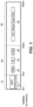
- LVTO procedures have different intervals for different visibility ranges; each interval has a set of requirements to guarantee a safe takeoff. See FIGS. 1 and 1A showing that a LVTO with a visibility interval of 150 meters and more does not require the assistance of the Head-Up Display (HUD), only external visual cues. With a visibility interval of 75 meters up to 150 meters, HUD assistance (as shown in Figure 1A , 1B ) is required along with, High Intensity Runway Lights (HIRL) and Center Lights (CL) for a safe takeoff. No takeoff of commercial aircraft is currently allowed when visibility is lower than 75 meters. This hinders the productivity, economically and operationally, of many airports and communities that are subjected to constant low visibility scenarios (fog, smog, heavy rain, etc.) throughout the year.
- HUD Head-Up Display
- the non-limiting technology herein provides the ability to take off in conditions where visibility is none or limited, while doing it safely to help prevent catastrophes like the Tenerife disaster.
- the present invention refers to an automatic takeoff system according to claim 1 and to a method for automatically controlling an aircraft according to claim 5, which are related to automatic takeoff capabilities of an aircraft.
- Preferred embodiments of the invention are defined in the appended dependent claims.
- FIGs 1-8 Certain specific details are set forth in the following descriptions and FIGs 1-8 to provide a thorough understanding of various embodiments of the technology. Well-known structures, systems, and methods often associated with such systems have not been shown or described in detail to avoid unnecessarily obscuring the description of the various embodiments of the technology. In addition, those of ordinary skill in the relevant art for understand that additional embodiments of the technology may be practiced without several of the details described below.
- Automating a LVTO would reduce the crew's required high workload during takeoff, allowing the pilots to control other operational aspects during this intense phase of flight. Automating an LVTO would also allow operation in conditions below 75 meters, which are not allowed today by any existing system. In many cases, automating the LVTO system for no-visibility or low-visibility takeoffs could prevent the loss of lives and equipment due to accidents induced by poor visibility takeoff conditions.
- the present invention provides a no/low visibility automatic takeoff system that obtains a runway reference centerline and aircraft pointing direction (via the aircraft's sensors) and automatically controls the aircraft pointing direction to track the runway reference centerline.
- the system of the invention may obtains a reference centerline and pointing direction, based on the airplane's own sensors and may provide an initial vector which is obtained based on the initial position of the aircraft the first piloted initiation of the takeoff roll. After this system obtains a centerline, it may track it based either on method 1 or method 2:
- the system Given a centerline reference, the system will act on the control surfaces (ailerons, roll spoilers, rudder, nose steering, etc.) in order to minimize the lateral distance from the airplane and the reference centerline
- the lateral control surfaces may be used secondarily to help control, based on a prescribed control logic.
- control law may act on both the lateral and the directional control surfaces primarily, in order to track a heading " ⁇ " and a bank “ ⁇ " references.
- the system Given a centerline reference, the system will act on the control surfaces (ailerons, roll spoilers, rudder, nose steering, etc.) in order to track a heading reference thus keeping the airplane within runway limits, parallel to the centerline. It shall measure, through the aircraft sensors, the heading angle " ⁇ ", compare it to the reference angle, obtained at the initiation of the takeoff roll, and apply a control logic through the FBW computer to reduce the error between the current measured " ⁇ " and the reference " ⁇ ".
- the control surfaces ailerons, roll spoilers, rudder, nose steering, etc.
- the lateral control surfaces may be used secondarily to help control, based on a prescribed control logic.
- control law may act on both the lateral and the directional control surfaces primarily, in order to track a heading " ⁇ " and a bank “ ⁇ " references.
- FIG. 1 & 1A show three different intervals of visibility during Low Visibility Takeoffs (LVTOs) and requirements necessary for a safe dispatch in each interval.
- the RVR regulations mandate that for a fair-visibility range 30- a visibility interval defined from 400 meters down to 150 meters-only external visibility cues (e.g., threshold 210, touch down zone 230, fixed distance markers 240, etc.) are necessary.
- a fair-visibility range 20 defined by a visibility interval of 149 meters down to 75 meters, runway markers (e.g., High Intensity Runway Lights (HIRLs) 22 , Center Lights (CLs) 24 , and Head-Up Display (HUD) 26 ) are obligatory for a takeoff (certain of these marker objects are usually integrated into the runway).
- HIRLs High Intensity Runway Lights
- CLs Center Lights
- HUD Head-Up Display
- the invention provides a system that allows low, and even zero, visibility takeoff without precision vision instrument guidance systems (e.g., HUD.)
- Embraer has put forth methods related to takeoff automation regarding longitudinal (pitch) and lateral (roll) axes.
- the present invention is independent of such other Embraer methods, it complements the takeoff automation through the utilization of the runway centerline.
- the system can be used in conjunction with Embraer automatic takeoff systems even in good visibility conditions. This will complement other Embraer methods to eliminate the human pilot action at takeoff, since it provides an automation in the directional axis (yaw), allowing the human pilot to monitor the takeoff and make top level decisions instead of performing manual takeoff actions.
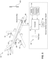
- Figure 5 shows an example non-limiting No/Low Visibility Automatic Takeoff System 50.
- An aircraft includes an onboard computer 52 that receives inputs from sensors including inertial sensor(s) 54, an enhanced GPS, and possibly other sensors such as a localizer 430 and/or optical IR sensors 68.
- the computer 52 also receives pilot input from an inceptor 58.
- the computer 52 uses these inputs develop a virtual centerline reference - basically an internal computer model 260 of the position of centerline 250 of a runway 200.
- the system 50 uses these sensors to track the pointing direction 265 of the aircraft 270 as it travels down the runway.
- Computer 52 employs automatic methods to control actuators 60, 62 for the rudder 64 and/or the nose wheel 66 to conform the aircraft's pointing direction 265 to the model 260 of the runway centerline 250 as the aircraft rolls down the runway 200 and rotates into the sky.
- the system 50 can use additional actuators and control surfaces (e.g., ailerons, roll spoilers) to control the aircraft 270 to continue to track the (extrapolated) runway centerline reference.
- the runway centerline reference for takeoffs may be generated even in poor visibility conditions by means of a method determining the runway centerline through a combination of both internal and external signals.
- the implementation of the aircraft's inertial sensing units (accelerometers and gyrosensors) 54 provide internal signals
- the Localizer (LOC) 430 and/or the Differential Global Position System (DGPS) 56 provides external signals.
- LOC Localizer
- DGPS Differential Global Position System
- the implemented system could allow for takeoff even in "no visibility" conditions, if and only if the system is proven to have enough accuracy to do so.
- the runway centerline reference for takeoffs even in poor visibility conditions is generated by means of a method encompassing a hybrid concept wherein the system 50 captures the track of the aircraft 270 in the initial takeoff roll (performed by the human pilot using inceptor 58) and uses the captured track for the rest of the takeoff run; i.e., it takes into account the course of the aircraft in the initial takeoff roll-that is determined by the pilot's inceptor inputs -and uses that determined course for the remainder of the takeoff.
- GAS Grounded Based Argumentation System
- DGPS Differential Global Positioning Systems
- the centerline generated from the initial run may be utilized by the automatic takeoff run until the aircraft 270 reaches an "automatic rotation" state at prescribed rotation velocity VR.
- the "automatic rotation” state is defined and produced in the same nature and manner as USP 8,793,040 B2 , incorporated herein by reference.
- the No/Low Visibility Auto-Takeoff (NLVTO) system 50 provided herein is capable of generating the runway centerline reference though many different techniques and combinations of techniques.
- an initial estimation of runway centerline is based on a trajectory derived from pilot inputs.
- the pilot aligns the aircraft 270 with the runway and initiates the takeoff normally.
- the system generates a reference for the aircraft to follow.
- the system 50 takes over and automatically guides the aircraft down the runway.
- the aircraft 270 is able to follow the generated reference using its inertial sensors 54 by maintaining a certain heading associated with the generated reference.
- GPS/GBAS The system may use information from the GPS/GBAS 56 signal to create a centerline reference to follow at the beginning of the takeoff roll.
- LOC/ILS instrument landing system
- the system may use a multi-spectral image processing device, hardware and software implemented using for example optical sensors 68, to create a centerline reference to follow since the beginning of the takeoff roll.
- the centerline reference can be an ultraviolet (UV) marker or an infrared (IR) marker.
- FIGS. 7A, 7B show example techniques for using external signals to generate a centerline reference 260.
- This method utilizes the Localizer 430, which transmits two signals to the aircraft on one of 40 ILS channels. One is modulated at 90 Hz 410, the other at 150 Hz 420. These are transmitted from co-located antennas 430. Each antenna transmits a narrow beam. This method is useful when there is no visibility of the runway centerline and the pilot cannot alight the aircraft and must rely on the centerline reference signal provided to the aircraft by the LOC 430.
- FIGS. 2 & 3 are illustrations of a runway 200 with an aircraft 270 preparing to takeoff in low visibility conditions.
- the runway of Fig. 3 has the following external markers:
- FIG. 3 depicts the pointing direction 265 of the aircraft 270 , the generated (virtual) centerline reference 260 , and a reference direction (e.g., true north, magnetic north, etc.) 280 of the aircraft.
- a reference direction e.g., true north, magnetic north, etc.
- the pointing direction 265 of the aircraft 270 is the direction the aircraft is currently pointing.
- the angle between the reference direction 280 and the direction in which the aircraft's nose is pointing make the heading of the aircraft 270 .
- the reference direction 280 i.e., can be implemented in a non-limiting manner by the aircraft's 270 air navigation system (e.g., in the Flight Management System). Techniques by which the pointing positions are generated will be explained further down, as well as their intended use.
- a centerline reference 260 is generated as defined in claim 1 and may further include any or all of the plethora of additional methods mentioned earlier.
- FIG. 6 shows in detail an example method for generating the centerline reference.
- all components related to any type of direction are represented as vectors stored within a computer of the aircraft 270 . These stored vectors can be calculated within the aircraft's system or inputted by a crew member.
- FIG. 4 is a close-up view of the aircraft 270 in FIGS. 2 & 3 . From this closer view, it is possible to see that the generated virtual centerline reference 260 is aligned with the runway's centerline 250 . It is also possible to see that the aircraft's pointing direction 265 is not aligned with the runway's centerline 250 . The deviation between the two vectors (centerline reference 260 and pointing direction 265 ) produce a heading angle ( ⁇ ) 290 .
- the reference direction 280 can be defined as the polar axis orthogonal with the centerline reference vector, and the current heading of the aircraft 265 points in the same direction of the virtual centerline reference 260 (the aircraft is defined as the pole).
- the reference direction 280 vector shown is determined at least partially by the aircraft's GPS, and is pointing North; it is determined to represent 0° and the centerline reference 260 represents 90°. Therefore, South is to be understood as 180° from the reference direction 280 . It should be noted that the reason why the reference direction 280 vector points North and the centerline reference 260 vector points East is due to the fact that in this example explanation both vectors match the cardinal for the simplification of the explanation.
- the system is capable of minimizing the deviation of the aircraft's heading via the aircraft's tracking to assure an aligned automatic takeoff.
- the aircraft 270 represented here as a point-mass, has a heading angle ( ⁇ ) 290 from the centerline reference 260.
- the runway has a defined Northern hemisphere and a Southern hemisphere with the centerline reference as the boundary for the contiguous hemispheres.
- the Northern hemisphere has a Northern-boundary 310-N and the Southern hemisphere has a Southern boundary 310-S .
- the two boundaries are the limits for the aircraft heading vector 265 of the system.
- the vectors can be represented in a non-limiting example, as vector projections.
- the heading vector 265 projects in the allowable deviation range 325-I (Inside the Range), the aircraft may continue to accelerate down the runway as long as this projection is within the allowable deviation range 325-I. If the heading vectors 265 projects outside of the allowable range and projects in the range of exceedance 325-O (Outside the Range), then system 50 must correct the aircraft 270's heading vector 265 .
- the reference direction 280 is orthogonal to the centerline reference 260 , it can be deduced that the reference direction vector 280 and the heading angle ( ⁇ ) 290 make an aircraft pointing direction 265 with a value of 90°+ ⁇ . If the heading vector 265 were on the Northern hemisphere, the system would consider the difference between both values (90°- ⁇ ) rather than the summation to find the aircraft pointing direction 265 .
- the system is configured to converge the sum or difference of both vectors to a value of 90° so that the heading vector 265 and the centerline reference can be aligned 260.
- the system 50 assures that the aircraft has a correct heading vector 265 for takeoff.
- a first method according to an example not corresponding to the invention as defined in the claims ensures the capability to stay within the Northern-boundary 310-N and Southern boundary 310-S by checking that the projections are in the allowable deviation range 325-I so the aircraft can keep accelerating down the runway. As the heading angle 290 converges to zero, the allowable deviation 325-I increase while the range of exceedance 325-O decreases.
- a second method according to an example not corresponding to the invention as defined in the claims relies on the aircraft's navigation capabilities to understand its heading (heading vector 265 ) relative to the virtual centerline reference 260 and minimizes the heading angle 290 between the two vectors.
- the invention uses a hybrid method wherein the pilot lines up the aircraft 270 with the centerline reference 260 and/or the centerline 250 during the takeoff roll until the system is able to capture an appropriate pointing direction 265 for the aircraft, and takeover the alignment of the aircraft 270 until takeoff is complete.
- All three methods receive data from an inertial sensor(s) 54 within the aircraft to check and maintain a correct pointing direction 265 , furthermore the actuation that changes the pointing direction 265 is executed by the flight control surfaces (ailerons, roll spoilers, rudder, etc.) and the nose-steering.
- flight control surfaces ailerons, roll spoilers, rudder, etc.
- the system Given a centerline reference, the system will act on the control surfaces (ailerons, roll spoilers, rudder, nose steering, etc.) in order to track a heading reference thus keeping the airplane within runway limits, parallel to the centerline. It measures, through the aircraft sensors, the heading angle " ⁇ ", compares it to the reference angle, obtained at the initiation of the takeoff roll, and applies a control logic through the FBW computer to reduce the error between the current measured " ⁇ " and the reference " ⁇ ".
- the control surfaces ailerons, roll spoilers, rudder, nose steering, etc.
- the lateral control surfaces are used secondarily to help control, based on a prescribed control logic.
- the control law will act on both the lateral and the directional control surfaces primarily, in order to track a heading " ⁇ " and a bank “ ⁇ " references.
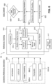
- FIG. 8 illustrates three parts of system 50 that help assure an automatic takeoff in low visibility conditions.
- the first phase or part 500 is the centerline reference generation 500
- the second phase or part 510 is the reference tracking 510
- the last phase or part 520 is the aircraft's takeoff roll 520 .
- These phases or parts 500, 510, 520 can be implemented any number of ways including for example software running on one or more processors, hardware logic, firmware, custom ASICs, etc.
- the generating phase 500 implements methods already described for generating a centerline reference for takeoff.
- One of the automatic techniques 500-A was described in detail on FIG. 7A, 7B .
- the manual technique 500-M is used, wherein pilot input is used so that the system has an appropriate pointing direction 265 for takeoff.
- An additional method is the composite technique 500-C that consists of the implementation of combinations of any of the previously mentioned techniques for generating the centerline reference.
- the manual technique is used, wherein the computer 52 acquires and stores a succession of data points indicative of headings of the aircraft as the pilot steers the aircraft down the runway along the runway centerline.
- the computer 52 uses this succession of data points to generate an internal centerline reference (vector) in two-dimensional space.
- the computer 52 is capable of acquiring such an internal centerline reference using the automatic techniques described above.
- the centerline reference is defined by a vector relative to an initial position of the aircraft.
- the second phase 510 of the automatic takeoff system is where the centerline reference tracking guides the aircraft along the determined vector in the correct heading.
- the data transmitted by the airport data base 517 , along with the data from the manual technique 500-M is processed in a processor 511 within an aircraft computer 52.
- the processor 511 determines whether there is enough data to generate an appropriate centerline reference 260 for the pointing direction 265 to track. If the system has enough information to generate the centerline reference 260 and enough integrity to track the reference, then the system uses an automatic procedure 515 for the takeoff roll. If the system does not have enough information to generate a centerline reference and/or does not have the integrity to track the reference, then the takeoff roll is started manually 513 .
- the system captures the track of the aircraft in the initial takeoff roll (performed by the human pilot) and uses it for the rest of the takeoff run.
- the system is configured to receive information from the pilot manual alignment of the aircraft pointing direction 265 and the centerline ( 250 , 260 ) and changes to an automatic procedure 515 when the system is able to validate a safe takeoff.
- the system produces signals to control the actuator of the aircraft.
- the actuator provides corrections to the pointing direction 265 by receiving instructions from the aircraft computer 52 that monitors the readings of the inertial sensor(s) 54 and assures that the pointing direction 265 remains aligned throughout the takeoff run.
- the system uses both the Flight Management System (e.g., FBW control law) and the inertial sensor(s) 54, determines the aircraft's current pointing heading 524 and minimizes deviation between the current pointing heading 524 vector and the centerline reference by automatically operating actuators 62, 64, to control the heading of the aircraft. It does this in a repetitive, continual manner so the two vectors remain closely aligned as the aircraft rolls down the runway.
- Flight Management System e.g., FBW control law
- the inertial sensor(s) 54 determines the aircraft's current pointing heading 524 and minimizes deviation between the current pointing heading 524 vector and the centerline reference by automatically operating actuators 62, 64, to control the heading of the aircraft. It does this in a repetitive, continual manner so the two vectors remain closely aligned as the aircraft rolls down the runway.
- the reference direction 280 is orthogonal to the centerline reference 260, it can be deduced that the reference direction vector 280 and the heading angle ( ⁇ ) 290 make an aircraft pointing direction 265 with a value of 90°+ ⁇ . If the heading vector 265 were on the Northern hemisphere, the system would consider the difference between both values (90°- ⁇ ) rather than the summation to find the aircraft pointing direction 265. The system is configured to converge the sum or difference of both vectors to a value of 90° so that the heading vector 265 and the centerline reference can be aligned 260.
- the system 50 assures using three methods that the aircraft has a correct heading vector 265 for takeoff.
- the first method ensures the capability to stay within the Northern-boundary 310-N and Southern boundary 310-S by checking that the projections are in the allowable deviation range 325-1 so the aircraft can keep accelerating down the runway. As the heading angle 290 converges to zero, the allowable deviation 325-1 increase while the range of exceedance 325 -O decreases.
- the second method relies on the aircraft's navigation capabilities to understand its heading (heading vector 265 ) relative to the virtual centerline reference 260 and minimizes the heading angle 290 between the two vectors.
- the third method is a hybrid method wherein the pilot lines up the aircraft 270 with the centerline reference 260 and/or the centerline 250 during the takeoff roll until the system is able to capture an appropriate pointing direction 265 for the aircraft, and takeover the alignment of the aircraft 270 until takeoff is complete.
- All three non-limiting methods receive data from an inertial sensor(s) 54 within the aircraft to check and maintain a correct pointing direction 265, furthermore the actuation that changes the pointing direction 265 is executed by the flight control surfaces (ailerons, roll spoilers, rudder, etc.) and the nose-steering.
- flight control surfaces ailerons, roll spoilers, rudder, etc.
- the system Given a centerline reference, the system will act on the control surfaces (ailerons, roll spoilers, rudder, nose steering, etc.) in order to track a heading reference thus keeping the airplane within runway limits, parallel to the centerline. It measures, through the aircraft sensors, the heading angle " ⁇ ", compares it to the reference angle, obtained at the initiation of the takeoff roll, and applies a control logic through the FBW computer to reduce the error between the current measured " ⁇ " and the reference " ⁇ ".
- the control surfaces ailerons, roll spoilers, rudder, nose steering, etc.
- the lateral control surfaces are used secondarily to help control, based on a prescribed control logic.
- the control law will act on both the lateral and the directional control surfaces primarily, in order to track a heading " ⁇ " and a bank “ ⁇ " references.
- FIG. 8 illustrates three parts of system 50 that help assure an automatic takeoff in low visibility conditions.
- the first phase or part 500 is the centerline reference generation 500
- the second phase or part 510 is the reference tracking 510
- the last phase or part 520 is the aircraft's takeoff roll 520.
- These phases or parts 500, 510, 520 can be implemented any number of ways including for example software running on one or more processors, hardware logic, firmware, custom ASICs, etc.
- the generating phase 500 implements methods already described for generating a centerline reference for takeoff.
- One of the automatic techniques 500-A was described in detail on FIG. 7A, 7B .
- the manual technique 500-M uses pilot input so that the system has an appropriate pointing direction 265 for takeoff.
- An additional method is the composite technique 500-C that consists of the implementation of combinations of any of the previously mentioned techniques for generating the centerline reference.
- the computer 52 acquires and stores a succession of data points indicative of headings of the aircraft as the pilot steers the aircraft down the runway along the runway centerline.
- the computer 52 uses this succession of data points to generate an internal centerline reference (vector) in two-dimensional space.
- the computer 52 is capable of acquiring such an internal centerline reference using the automatic techniques described above.
- the centerline reference is defined by a vector relative to an initial position of the aircraft.
- the second phase 510 of the automatic takeoff system is where the centerline reference tracking guides the aircraft along the determined vector in the correct heading.
- the data transmitted by the airport data base 517, along with the data from the automatic techniques 500-A , or manual technique 500-M , or the composite technique 500-C is processed in a processor 511 within an aircraft computer 52.
- the processor 511 determines whether there is enough data to generate an appropriate centerline reference 260 for the pointing direction 265 to track. If the system has enough information to generate the centerline reference 260 and enough integrity to track the reference, then the system uses an automatic procedure 515 for the takeoff roll. If the system does not have enough information to generate a centerline reference and/or does not have the integrity to track the reference, then the takeoff roll is started manually 513.
- the system captures the track of the aircraft in the initial takeoff roll (performed by the human pilot) and uses it for the rest of the takeoff run.
- the system is configured to receive information from the pilot manual alignment of the aircraft pointing direction 265 and the centerline ( 250, 260 ) and changes to an automatic procedure 515 when the system is able to validate a safe takeoff.
- the system produces signals to control the actuator of the aircraft.
- the actuator provides corrections to the pointing direction 265 by receiving instructions from the aircraft computer 52 that monitors the readings of the inertial sensor(s) 54 and assures that the pointing direction 265 remains aligned throughout the takeoff run.
- the system uses both the Flight Management System (e.g., FBW control law) and the inertial sensor(s) 54, determines the aircraft's current pointing heading 524 and minimizes deviation between the current pointing heading 524 vector and the centerline reference by automatically operating actuators 62, 64, to control the heading of the aircraft. It does this in a repetitive, continual manner so the two vectors remain closely aligned as the aircraft rolls down the runway.
- Flight Management System e.g., FBW control law
- the inertial sensor(s) 54 determines the aircraft's current pointing heading 524 and minimizes deviation between the current pointing heading 524 vector and the centerline reference by automatically operating actuators 62, 64, to control the heading of the aircraft. It does this in a repetitive, continual manner so the two vectors remain closely aligned as the aircraft rolls down the runway.
Landscapes
- Engineering & Computer Science (AREA)
- Aviation & Aerospace Engineering (AREA)
- Physics & Mathematics (AREA)
- General Physics & Mathematics (AREA)
- Radar, Positioning & Navigation (AREA)
- Remote Sensing (AREA)
- Automation & Control Theory (AREA)
- Traffic Control Systems (AREA)
- Navigation (AREA)
Claims (8)
- Automatisches Startsystem, aufweisend:einen Trägheitssensor (54), welcher dafür eingerichtet ist, an Bord eines Flugzeugs angeordnet zu sein, und welcher dafür eingerichtet ist, die Richtung, in welche das Flugzeug zeigt, zu erfassen; undmindestens einen Prozessor (511), welcher dafür eingerichtet ist, eine virtuelle Referenzmittellinie während eines Anfangsabschnitts einer Startrollstrecke zu erzeugen, wobei ein Computer (52) eine Abfolge von Datenpunkten, welche Steuerkurse des Flugzeugs anzeigen, erfasst und speichert, während der Pilot das Flugzeug entlang der Mittellinie der Start- und Landebahn auf der Start- und Landebahn steuert, wobei die virtuelle Referenzmittellinie den Weg des Flugzeugs anzeigt, während dieses einer Mittellinie der Start- und Landebahn folgt, wobei der Prozessor ferner dafür eingerichtet ist, eine Abweichung zwischen der Richtung, in welche das Flugzeug zeigt, und der erzeugten virtuellen Referenzmittellinie zu vergleichen und automatisch ein Stellantriebssteuersignal auszugeben, welches die Richtung, in welche das Flugzeug zeigt, an die erzeugte virtuelle Referenzmittellinie anpasst.
- System nach Anspruch 1, wobei die erzeugte virtuelle Referenzmittellinie als Reaktion auf Daten erzeugt wird, welche von einem oder sämtlichen Systemen aus der Gruppe umfassend ein differenzielles globales Positionierungssystem, ein bodengestütztes Ergänzungssystem, ein Instrumentenlandesystem, einen Lokalisator und ein multispektrales Bildverarbeitungssystem erlangt werden.
- System nach Anspruch 1 oder 2, wobei der mindestens eine Prozessor (511) in der Lage ist, zu bestimmen, ob die Daten ausreichen, um den Wert der erzeugten Referenzmittellinie und den Wert der aktuellen Richtung miteinander zu vergleichen, oder ob zusätzlich Eingaben erforderlich sind.
- System nach einem der vorstehenden Ansprüche, wobei der Prozessor (511) ferner dafür eingerichtet ist, Steuersignalanweisungen basierend auf der ergänzenden Eingabe während der Ausrichtung für die Startrollstrecke auszuführen; und/oder wobei der Prozessor (511) ferner dafür eingerichtet ist, eine automatische Referenzmittellinienverfolgung fortzuführen, wenn der Prozessor feststellt, dass ein Trägheitssensor die Übereinstimmung der aktuellen Richtung, in welche das Flugzeug zeigt, mit der Referenzmittellinie anzeigt; und/oderwobei der Prozessor (511) ferner dafür eingerichtet ist, eine Abfolge aktueller Richtungen, in welche das Flugzeug während des Rollens auf der Startstrecke zeigt, zu speichern und Steuersignale an den Stellantrieb zu senden, um Korrekturen bereitzustellen, wenn Trägheitssensoren erfassen, dass die Richtung, in welche das Flugzeug zeigt, von der Referenz abweicht; und/oderwobei der Prozessor (511) dafür eingerichtet ist, ein Rückführungssignal, welches die aktuelle Richtung, in welche das Flugzeugt während des Rollens auf der Startstrecke zeigt, wiederholt aktualisiert, von Trägheitssensoren zu empfangen.
- Verfahren zum automatischen Steuern eines Flugzeugs, umfassend:(a) Erzeugen einer virtuellen Referenzmittellinie, welche den Weg eines manuell gesteuerten Flugzeugs während eines Anfangsabschnitts einer Startrollstrecke anzeigt, wobei ein Computer (52) eine Abfolge von Datenpunkten, welche Steuerkurse des Flugzeugs anzeigen, erfasst und speichert, während der Pilot das Flugzeug entlang der Mittellinie der Start- und Landebahn steuert; und(b) automatisches Steuern des Steuerkurses des Flugzeugs, sodass das Flugzeug während eines späteren Abschnitts der Startrollstrecke dem Weg der virtuellen Referenzmittellinie folgt.
- Verfahren nach Anspruch 5, ferner umfassend das wiederholte Bestimmen eines aktualisierten aktuellen Steuerkurses des Flugzeugs mittels eines Trägheitssensors, und Weitergeben des aktualisierten aktuellen Steuerkurses an einen Referenzmittellinienverfolger.
- Verfahren nach Anspruch 5 oder 6, ferner umfassend Bestimmen der Abweichung zwischen der virtuellen Referenzmittellinie und dem aktuellen Steuerkurs des Flugzeugs mittels des Referenzmittellinienverfolgers des Systems.
- Verfahren nach einem der Ansprüche 5 bis 7, ferner umfassend Weiterleiten von Korrektursignalen vom Referenzmittellinienverfolger an einen Stellantrieb, welcher mindestens eine Steueroberfläche und/oder Einrad-/Bugrad-Steuerung steuert, mittels eines internen Computers.
Applications Claiming Priority (1)
| Application Number | Priority Date | Filing Date | Title |
|---|---|---|---|
| US16/226,141 US11074820B2 (en) | 2018-12-19 | 2018-12-19 | Low/No visibility takeoff system |
Publications (2)
| Publication Number | Publication Date |
|---|---|
| EP3671395A1 EP3671395A1 (de) | 2020-06-24 |
| EP3671395B1 true EP3671395B1 (de) | 2023-04-19 |
Family
ID=68766554
Family Applications (1)
| Application Number | Title | Priority Date | Filing Date |
|---|---|---|---|
| EP19213080.5A Active EP3671395B1 (de) | 2018-12-19 | 2019-12-03 | Startsystem für keine/geringe sicht |
Country Status (4)
| Country | Link |
|---|---|
| US (1) | US11074820B2 (de) |
| EP (1) | EP3671395B1 (de) |
| CN (1) | CN111341154B (de) |
| BR (1) | BR102019026952A2 (de) |
Families Citing this family (10)
| Publication number | Priority date | Publication date | Assignee | Title |
|---|---|---|---|---|
| US11170656B2 (en) * | 2018-11-28 | 2021-11-09 | The Boeing Company | Predicting low visibility set-up options for an airport moving map |
| US12555485B2 (en) | 2020-11-26 | 2026-02-17 | Bae Systems Plc | Autonomous taxiing method and apparatus |
| US12051337B2 (en) | 2021-02-17 | 2024-07-30 | Honeywell International Inc. | Systems and methods for low visibility guidance and taxi routing |
| KR20230150181A (ko) * | 2022-04-21 | 2023-10-30 | 현대자동차주식회사 | 비행체 제어 시스템 및 방법 |
| USD1122955S1 (en) * | 2024-12-09 | 2026-04-21 | Jeppesen Foreflight, Inc. | Display screen or portion thereof with animated graphical user interface |
| USD1121653S1 (en) * | 2024-12-09 | 2026-04-07 | Jeppesen Foreflight, Inc. | Display screen or portion thereof with animated graphical user interface |
| USD1122274S1 (en) * | 2024-12-09 | 2026-04-14 | Jeppesen Foreflight, Inc. | Display screen or portion thereof with graphical user interface |
| USD1122956S1 (en) * | 2024-12-09 | 2026-04-21 | Jeppesen Foreflight, Inc. | Display screen or portion thereof with animated graphical user interface |
| USD1121651S1 (en) * | 2024-12-09 | 2026-04-07 | Jeppesen Foreflight, Inc. | Display screen or portion thereof with animated graphical user interface |
| USD1122957S1 (en) * | 2024-12-09 | 2026-04-21 | Jeppesen Foreflight, Inc. | Display screen or portion thereof with animated graphical user interface |
Family Cites Families (11)
| Publication number | Priority date | Publication date | Assignee | Title |
|---|---|---|---|---|
| US5008825A (en) * | 1989-05-01 | 1991-04-16 | Nadkarni Arun A | Apparatus and methods for automatically maintaining aircraft track angle |
| US7364121B2 (en) * | 2005-03-14 | 2008-04-29 | The Boeing Company | Methods and systems for automatically controlling aircraft takeoff rolls |
| CN101244765B (zh) * | 2008-03-14 | 2010-06-02 | 南京航空航天大学 | 低能见度下飞机起飞着陆的视觉导引和监控系统及方法 |
| US20110040431A1 (en) * | 2009-08-11 | 2011-02-17 | Honeywell International Inc. | Automated take off control system and method |
| US20110106345A1 (en) * | 2009-11-03 | 2011-05-05 | Takacs Robert S | Low visibility landing system |
| US8793040B2 (en) | 2011-06-10 | 2014-07-29 | Embraer S.A. | Climb-optimized auto takeoff system |
| US8868265B2 (en) * | 2011-11-30 | 2014-10-21 | Honeywell International Inc. | System and method for aligning aircraft and runway headings during takeoff roll |
| US8560149B1 (en) * | 2012-09-20 | 2013-10-15 | Honeywell International Inc. | Systems and methods for takeoff assistance and analysis |
| US9470528B1 (en) * | 2015-03-26 | 2016-10-18 | Honeywell International Inc. | Aircraft synthetic vision systems utilizing data from local area augmentation systems, and methods for operating such aircraft synthetic vision systems |
| US10878709B2 (en) * | 2018-07-19 | 2020-12-29 | The Boeing Company | System, method, and computer readable medium for autonomous airport runway navigation |
| US11364992B2 (en) * | 2018-10-23 | 2022-06-21 | The Boeing Company | Aligning aircraft with runway centerline during takeoff |
-
2018
- 2018-12-19 US US16/226,141 patent/US11074820B2/en active Active
-
2019
- 2019-12-02 CN CN201911212990.4A patent/CN111341154B/zh active Active
- 2019-12-03 EP EP19213080.5A patent/EP3671395B1/de active Active
- 2019-12-17 BR BR102019026952-9A patent/BR102019026952A2/pt active Search and Examination
Also Published As
| Publication number | Publication date |
|---|---|
| US11074820B2 (en) | 2021-07-27 |
| CN111341154B (zh) | 2023-07-25 |
| US20200202726A1 (en) | 2020-06-25 |
| EP3671395A1 (de) | 2020-06-24 |
| CN111341154A (zh) | 2020-06-26 |
| BR102019026952A2 (pt) | 2020-11-10 |
Similar Documents
| Publication | Publication Date | Title |
|---|---|---|
| EP3671395B1 (de) | Startsystem für keine/geringe sicht | |
| Marut et al. | ArUco markers pose estimation in UAV landing aid system | |
| RU2712716C2 (ru) | Беспилотный летательный аппарат и способ безопасной посадки беспилотного летательного аппарата | |
| US9260180B2 (en) | Autonomous and automatic landing method and system | |
| RU2384889C1 (ru) | Система пилотирования летательного аппарата для пилотирования летательного аппарата, по меньшей мере, во время автономного захода на посадку | |
| RU2692306C2 (ru) | Система сопровождения для беспилотных авиационных транспортных средств | |
| US5608392A (en) | Aircraft collision-avoidance device, notably ground collision, by control of angle of descent | |
| US7917254B2 (en) | Aircraft guidance using localizer capture criteria for rectilinear displacement data | |
| US12315268B2 (en) | Vision-based landing system | |
| US7412324B1 (en) | Flight management system with precision merging | |
| EP3709116B1 (de) | Ableitung der führungsabweichung aus einem hybriden positionslösungssystem mit hoher sicherheit und verfahren | |
| CN102620736A (zh) | 一种无人机的导航方法 | |
| CN101366064A (zh) | 自动进场时用于协助驾驶飞行器的方法和装置 | |
| CN107003668B (zh) | 用于引导飞机的方法及装置 | |
| US20230150690A1 (en) | Systems and methods for providing safe landing assistance for a vehicle | |
| US12205476B2 (en) | Aerial vehicles with machine vision | |
| US12441486B2 (en) | Landing system and method | |
| US11915603B2 (en) | Docking guidance display methods and systems | |
| US7941251B2 (en) | Consistent localizer captures | |
| CN108572657A (zh) | 用于旋翼飞行器的自动领航装置和包括该装置的旋翼飞行器 | |
| Beall et al. | Optic flow and visual analysis of the base-to-final turn | |
| CA2795775A1 (en) | Method of guidance for aircraft trajectory correction | |
| US12179936B2 (en) | Landing zone landing assistance system for a rotary wing aircraft | |
| US20220157182A1 (en) | System and Method For Flight and Landing Navigation for Unpiloted Vertical and Take-Off Landing (UVTOL) Aircraft | |
| EP4181104B1 (de) | Systeme und verfahren zur bereitstellung einer sicheren landehilfe für ein fahrzeug |
Legal Events
| Date | Code | Title | Description |
|---|---|---|---|
| PUAI | Public reference made under article 153(3) epc to a published international application that has entered the european phase |
Free format text: ORIGINAL CODE: 0009012 |
|
| STAA | Information on the status of an ep patent application or granted ep patent |
Free format text: STATUS: THE APPLICATION HAS BEEN PUBLISHED |
|
| AK | Designated contracting states |
Kind code of ref document: A1 Designated state(s): AL AT BE BG CH CY CZ DE DK EE ES FI FR GB GR HR HU IE IS IT LI LT LU LV MC MK MT NL NO PL PT RO RS SE SI SK SM TR |
|
| AX | Request for extension of the european patent |
Extension state: BA ME |
|
| RIN1 | Information on inventor provided before grant (corrected) |
Inventor name: DE SOUZA JUNIOR, RUBENS MONTEIRO Inventor name: GUEDES, PATRICE LONDON Inventor name: CARNEIRO, LUIZ GUSTAVO MEDEIROS Inventor name: REIS, JOSE ROBERTO FERREIRA DE CAMARGO CLARK Inventor name: BARBOSA, NELSON Inventor name: KESTENBACH, THOMAS |
|
| STAA | Information on the status of an ep patent application or granted ep patent |
Free format text: STATUS: REQUEST FOR EXAMINATION WAS MADE |
|
| 17P | Request for examination filed |
Effective date: 20201222 |
|
| RBV | Designated contracting states (corrected) |
Designated state(s): AL AT BE BG CH CY CZ DE DK EE ES FI FR GB GR HR HU IE IS IT LI LT LU LV MC MK MT NL NO PL PT RO RS SE SI SK SM TR |
|
| STAA | Information on the status of an ep patent application or granted ep patent |
Free format text: STATUS: EXAMINATION IS IN PROGRESS |
|
| 17Q | First examination report despatched |
Effective date: 20210716 |
|
| GRAP | Despatch of communication of intention to grant a patent |
Free format text: ORIGINAL CODE: EPIDOSNIGR1 |
|
| STAA | Information on the status of an ep patent application or granted ep patent |
Free format text: STATUS: GRANT OF PATENT IS INTENDED |
|
| RIC1 | Information provided on ipc code assigned before grant |
Ipc: G05D 1/06 20060101ALI20221205BHEP Ipc: G05D 1/02 20200101AFI20221205BHEP |
|
| INTG | Intention to grant announced |
Effective date: 20230104 |
|
| GRAS | Grant fee paid |
Free format text: ORIGINAL CODE: EPIDOSNIGR3 |
|
| GRAA | (expected) grant |
Free format text: ORIGINAL CODE: 0009210 |
|
| STAA | Information on the status of an ep patent application or granted ep patent |
Free format text: STATUS: THE PATENT HAS BEEN GRANTED |
|
| AK | Designated contracting states |
Kind code of ref document: B1 Designated state(s): AL AT BE BG CH CY CZ DE DK EE ES FI FR GB GR HR HU IE IS IT LI LT LU LV MC MK MT NL NO PL PT RO RS SE SI SK SM TR |
|
| REG | Reference to a national code |
Ref country code: GB Ref legal event code: FG4D |
|
| REG | Reference to a national code |
Ref country code: CH Ref legal event code: EP |
|
| REG | Reference to a national code |
Ref country code: DE Ref legal event code: R096 Ref document number: 602019027690 Country of ref document: DE |
|
| REG | Reference to a national code |
Ref country code: IE Ref legal event code: FG4D |
|
| REG | Reference to a national code |
Ref country code: AT Ref legal event code: REF Ref document number: 1561672 Country of ref document: AT Kind code of ref document: T Effective date: 20230515 |
|
| REG | Reference to a national code |
Ref country code: LT Ref legal event code: MG9D |
|
| REG | Reference to a national code |
Ref country code: NL Ref legal event code: MP Effective date: 20230419 |
|
| REG | Reference to a national code |
Ref country code: AT Ref legal event code: MK05 Ref document number: 1561672 Country of ref document: AT Kind code of ref document: T Effective date: 20230419 |
|
| PG25 | Lapsed in a contracting state [announced via postgrant information from national office to epo] |
Ref country code: NL Free format text: LAPSE BECAUSE OF FAILURE TO SUBMIT A TRANSLATION OF THE DESCRIPTION OR TO PAY THE FEE WITHIN THE PRESCRIBED TIME-LIMIT Effective date: 20230419 |
|
| PG25 | Lapsed in a contracting state [announced via postgrant information from national office to epo] |
Ref country code: SE Free format text: LAPSE BECAUSE OF FAILURE TO SUBMIT A TRANSLATION OF THE DESCRIPTION OR TO PAY THE FEE WITHIN THE PRESCRIBED TIME-LIMIT Effective date: 20230419 Ref country code: PT Free format text: LAPSE BECAUSE OF FAILURE TO SUBMIT A TRANSLATION OF THE DESCRIPTION OR TO PAY THE FEE WITHIN THE PRESCRIBED TIME-LIMIT Effective date: 20230821 Ref country code: NO Free format text: LAPSE BECAUSE OF FAILURE TO SUBMIT A TRANSLATION OF THE DESCRIPTION OR TO PAY THE FEE WITHIN THE PRESCRIBED TIME-LIMIT Effective date: 20230719 Ref country code: ES Free format text: LAPSE BECAUSE OF FAILURE TO SUBMIT A TRANSLATION OF THE DESCRIPTION OR TO PAY THE FEE WITHIN THE PRESCRIBED TIME-LIMIT Effective date: 20230419 Ref country code: AT Free format text: LAPSE BECAUSE OF FAILURE TO SUBMIT A TRANSLATION OF THE DESCRIPTION OR TO PAY THE FEE WITHIN THE PRESCRIBED TIME-LIMIT Effective date: 20230419 |
|
| REG | Reference to a national code |
Ref country code: DE Ref legal event code: R079 Ref document number: 602019027690 Country of ref document: DE Free format text: PREVIOUS MAIN CLASS: G05D0001020000 Ipc: G05D0001430000 |
|
| PG25 | Lapsed in a contracting state [announced via postgrant information from national office to epo] |
Ref country code: RS Free format text: LAPSE BECAUSE OF FAILURE TO SUBMIT A TRANSLATION OF THE DESCRIPTION OR TO PAY THE FEE WITHIN THE PRESCRIBED TIME-LIMIT Effective date: 20230419 Ref country code: PL Free format text: LAPSE BECAUSE OF FAILURE TO SUBMIT A TRANSLATION OF THE DESCRIPTION OR TO PAY THE FEE WITHIN THE PRESCRIBED TIME-LIMIT Effective date: 20230419 Ref country code: LV Free format text: LAPSE BECAUSE OF FAILURE TO SUBMIT A TRANSLATION OF THE DESCRIPTION OR TO PAY THE FEE WITHIN THE PRESCRIBED TIME-LIMIT Effective date: 20230419 Ref country code: LT Free format text: LAPSE BECAUSE OF FAILURE TO SUBMIT A TRANSLATION OF THE DESCRIPTION OR TO PAY THE FEE WITHIN THE PRESCRIBED TIME-LIMIT Effective date: 20230419 Ref country code: IS Free format text: LAPSE BECAUSE OF FAILURE TO SUBMIT A TRANSLATION OF THE DESCRIPTION OR TO PAY THE FEE WITHIN THE PRESCRIBED TIME-LIMIT Effective date: 20230819 Ref country code: HR Free format text: LAPSE BECAUSE OF FAILURE TO SUBMIT A TRANSLATION OF THE DESCRIPTION OR TO PAY THE FEE WITHIN THE PRESCRIBED TIME-LIMIT Effective date: 20230419 Ref country code: GR Free format text: LAPSE BECAUSE OF FAILURE TO SUBMIT A TRANSLATION OF THE DESCRIPTION OR TO PAY THE FEE WITHIN THE PRESCRIBED TIME-LIMIT Effective date: 20230720 Ref country code: AL Free format text: LAPSE BECAUSE OF FAILURE TO SUBMIT A TRANSLATION OF THE DESCRIPTION OR TO PAY THE FEE WITHIN THE PRESCRIBED TIME-LIMIT Effective date: 20230419 |
|
| PG25 | Lapsed in a contracting state [announced via postgrant information from national office to epo] |
Ref country code: FI Free format text: LAPSE BECAUSE OF FAILURE TO SUBMIT A TRANSLATION OF THE DESCRIPTION OR TO PAY THE FEE WITHIN THE PRESCRIBED TIME-LIMIT Effective date: 20230419 |
|
| PG25 | Lapsed in a contracting state [announced via postgrant information from national office to epo] |
Ref country code: SK Free format text: LAPSE BECAUSE OF FAILURE TO SUBMIT A TRANSLATION OF THE DESCRIPTION OR TO PAY THE FEE WITHIN THE PRESCRIBED TIME-LIMIT Effective date: 20230419 |
|
| REG | Reference to a national code |
Ref country code: DE Ref legal event code: R097 Ref document number: 602019027690 Country of ref document: DE |
|
| PG25 | Lapsed in a contracting state [announced via postgrant information from national office to epo] |
Ref country code: SM Free format text: LAPSE BECAUSE OF FAILURE TO SUBMIT A TRANSLATION OF THE DESCRIPTION OR TO PAY THE FEE WITHIN THE PRESCRIBED TIME-LIMIT Effective date: 20230419 Ref country code: SK Free format text: LAPSE BECAUSE OF FAILURE TO SUBMIT A TRANSLATION OF THE DESCRIPTION OR TO PAY THE FEE WITHIN THE PRESCRIBED TIME-LIMIT Effective date: 20230419 Ref country code: RO Free format text: LAPSE BECAUSE OF FAILURE TO SUBMIT A TRANSLATION OF THE DESCRIPTION OR TO PAY THE FEE WITHIN THE PRESCRIBED TIME-LIMIT Effective date: 20230419 Ref country code: EE Free format text: LAPSE BECAUSE OF FAILURE TO SUBMIT A TRANSLATION OF THE DESCRIPTION OR TO PAY THE FEE WITHIN THE PRESCRIBED TIME-LIMIT Effective date: 20230419 Ref country code: DK Free format text: LAPSE BECAUSE OF FAILURE TO SUBMIT A TRANSLATION OF THE DESCRIPTION OR TO PAY THE FEE WITHIN THE PRESCRIBED TIME-LIMIT Effective date: 20230419 Ref country code: CZ Free format text: LAPSE BECAUSE OF FAILURE TO SUBMIT A TRANSLATION OF THE DESCRIPTION OR TO PAY THE FEE WITHIN THE PRESCRIBED TIME-LIMIT Effective date: 20230419 |
|
| PLBE | No opposition filed within time limit |
Free format text: ORIGINAL CODE: 0009261 |
|
| STAA | Information on the status of an ep patent application or granted ep patent |
Free format text: STATUS: NO OPPOSITION FILED WITHIN TIME LIMIT |
|
| 26N | No opposition filed |
Effective date: 20240122 |
|
| PG25 | Lapsed in a contracting state [announced via postgrant information from national office to epo] |
Ref country code: SI Free format text: LAPSE BECAUSE OF FAILURE TO SUBMIT A TRANSLATION OF THE DESCRIPTION OR TO PAY THE FEE WITHIN THE PRESCRIBED TIME-LIMIT Effective date: 20230419 |
|
| PG25 | Lapsed in a contracting state [announced via postgrant information from national office to epo] |
Ref country code: SI Free format text: LAPSE BECAUSE OF FAILURE TO SUBMIT A TRANSLATION OF THE DESCRIPTION OR TO PAY THE FEE WITHIN THE PRESCRIBED TIME-LIMIT Effective date: 20230419 Ref country code: IT Free format text: LAPSE BECAUSE OF FAILURE TO SUBMIT A TRANSLATION OF THE DESCRIPTION OR TO PAY THE FEE WITHIN THE PRESCRIBED TIME-LIMIT Effective date: 20230419 |
|
| REG | Reference to a national code |
Ref country code: CH Ref legal event code: PL |
|
| PG25 | Lapsed in a contracting state [announced via postgrant information from national office to epo] |
Ref country code: LU Free format text: LAPSE BECAUSE OF NON-PAYMENT OF DUE FEES Effective date: 20231203 |
|
| PG25 | Lapsed in a contracting state [announced via postgrant information from national office to epo] |
Ref country code: MC Free format text: LAPSE BECAUSE OF FAILURE TO SUBMIT A TRANSLATION OF THE DESCRIPTION OR TO PAY THE FEE WITHIN THE PRESCRIBED TIME-LIMIT Effective date: 20230419 |
|
| REG | Reference to a national code |
Ref country code: BE Ref legal event code: MM Effective date: 20231231 |
|
| PG25 | Lapsed in a contracting state [announced via postgrant information from national office to epo] |
Ref country code: MC Free format text: LAPSE BECAUSE OF FAILURE TO SUBMIT A TRANSLATION OF THE DESCRIPTION OR TO PAY THE FEE WITHIN THE PRESCRIBED TIME-LIMIT Effective date: 20230419 Ref country code: LU Free format text: LAPSE BECAUSE OF NON-PAYMENT OF DUE FEES Effective date: 20231203 |
|
| REG | Reference to a national code |
Ref country code: IE Ref legal event code: MM4A |
|
| PG25 | Lapsed in a contracting state [announced via postgrant information from national office to epo] |
Ref country code: IE Free format text: LAPSE BECAUSE OF NON-PAYMENT OF DUE FEES Effective date: 20231203 |
|
| PG25 | Lapsed in a contracting state [announced via postgrant information from national office to epo] |
Ref country code: BE Free format text: LAPSE BECAUSE OF NON-PAYMENT OF DUE FEES Effective date: 20231231 |
|
| PG25 | Lapsed in a contracting state [announced via postgrant information from national office to epo] |
Ref country code: FR Free format text: LAPSE BECAUSE OF NON-PAYMENT OF DUE FEES Effective date: 20231231 |
|
| PG25 | Lapsed in a contracting state [announced via postgrant information from national office to epo] |
Ref country code: CH Free format text: LAPSE BECAUSE OF NON-PAYMENT OF DUE FEES Effective date: 20231231 |
|
| PG25 | Lapsed in a contracting state [announced via postgrant information from national office to epo] |
Ref country code: IE Free format text: LAPSE BECAUSE OF NON-PAYMENT OF DUE FEES Effective date: 20231203 Ref country code: FR Free format text: LAPSE BECAUSE OF NON-PAYMENT OF DUE FEES Effective date: 20231231 Ref country code: CH Free format text: LAPSE BECAUSE OF NON-PAYMENT OF DUE FEES Effective date: 20231231 Ref country code: BE Free format text: LAPSE BECAUSE OF NON-PAYMENT OF DUE FEES Effective date: 20231231 |
|
| PG25 | Lapsed in a contracting state [announced via postgrant information from national office to epo] |
Ref country code: BG Free format text: LAPSE BECAUSE OF FAILURE TO SUBMIT A TRANSLATION OF THE DESCRIPTION OR TO PAY THE FEE WITHIN THE PRESCRIBED TIME-LIMIT Effective date: 20230419 |
|
| PG25 | Lapsed in a contracting state [announced via postgrant information from national office to epo] |
Ref country code: BG Free format text: LAPSE BECAUSE OF FAILURE TO SUBMIT A TRANSLATION OF THE DESCRIPTION OR TO PAY THE FEE WITHIN THE PRESCRIBED TIME-LIMIT Effective date: 20230419 |
|
| PG25 | Lapsed in a contracting state [announced via postgrant information from national office to epo] |
Ref country code: CY Free format text: LAPSE BECAUSE OF FAILURE TO SUBMIT A TRANSLATION OF THE DESCRIPTION OR TO PAY THE FEE WITHIN THE PRESCRIBED TIME-LIMIT; INVALID AB INITIO Effective date: 20191203 |
|
| PG25 | Lapsed in a contracting state [announced via postgrant information from national office to epo] |
Ref country code: HU Free format text: LAPSE BECAUSE OF FAILURE TO SUBMIT A TRANSLATION OF THE DESCRIPTION OR TO PAY THE FEE WITHIN THE PRESCRIBED TIME-LIMIT; INVALID AB INITIO Effective date: 20191203 |
|
| PG25 | Lapsed in a contracting state [announced via postgrant information from national office to epo] |
Ref country code: TR Free format text: LAPSE BECAUSE OF FAILURE TO SUBMIT A TRANSLATION OF THE DESCRIPTION OR TO PAY THE FEE WITHIN THE PRESCRIBED TIME-LIMIT Effective date: 20230419 |
|
| PGFP | Annual fee paid to national office [announced via postgrant information from national office to epo] |
Ref country code: GB Payment date: 20251229 Year of fee payment: 7 |
|
| PGFP | Annual fee paid to national office [announced via postgrant information from national office to epo] |
Ref country code: DE Payment date: 20251229 Year of fee payment: 7 |