EP3671198A1 - Strip structure for measuring potassium ions - Google Patents
Strip structure for measuring potassium ions Download PDFInfo
- Publication number
- EP3671198A1 EP3671198A1 EP19215501.8A EP19215501A EP3671198A1 EP 3671198 A1 EP3671198 A1 EP 3671198A1 EP 19215501 A EP19215501 A EP 19215501A EP 3671198 A1 EP3671198 A1 EP 3671198A1
- Authority
- EP
- European Patent Office
- Prior art keywords
- strip
- working electrode
- potassium
- ion selective
- potassium ion
- Prior art date
- Legal status (The legal status is an assumption and is not a legal conclusion. Google has not performed a legal analysis and makes no representation as to the accuracy of the status listed.)
- Granted
Links
Images





Classifications
-
- G—PHYSICS
- G01—MEASURING; TESTING
- G01N—INVESTIGATING OR ANALYSING MATERIALS BY DETERMINING THEIR CHEMICAL OR PHYSICAL PROPERTIES
- G01N27/00—Investigating or analysing materials by the use of electric, electrochemical, or magnetic means
- G01N27/26—Investigating or analysing materials by the use of electric, electrochemical, or magnetic means by investigating electrochemical variables; by using electrolysis or electrophoresis
- G01N27/28—Electrolytic cell components
- G01N27/30—Electrodes, e.g. test electrodes; Half-cells
- G01N27/333—Ion-selective electrodes or membranes
- G01N27/3335—Ion-selective electrodes or membranes the membrane containing at least one organic component
-
- G—PHYSICS
- G01—MEASURING; TESTING
- G01N—INVESTIGATING OR ANALYSING MATERIALS BY DETERMINING THEIR CHEMICAL OR PHYSICAL PROPERTIES
- G01N33/00—Investigating or analysing materials by specific methods not covered by groups G01N1/00 - G01N31/00
- G01N33/48—Biological material, e.g. blood, urine; Haemocytometers
- G01N33/483—Physical analysis of biological material
- G01N33/487—Physical analysis of biological material of liquid biological material
- G01N33/49—Blood
- G01N33/491—Blood by separating the blood components
-
- G—PHYSICS
- G01—MEASURING; TESTING
- G01N—INVESTIGATING OR ANALYSING MATERIALS BY DETERMINING THEIR CHEMICAL OR PHYSICAL PROPERTIES
- G01N27/00—Investigating or analysing materials by the use of electric, electrochemical, or magnetic means
- G01N27/26—Investigating or analysing materials by the use of electric, electrochemical, or magnetic means by investigating electrochemical variables; by using electrolysis or electrophoresis
- G01N27/28—Electrolytic cell components
- G01N27/30—Electrodes, e.g. test electrodes; Half-cells
- G01N27/333—Ion-selective electrodes or membranes
-
- B—PERFORMING OPERATIONS; TRANSPORTING
- B01—PHYSICAL OR CHEMICAL PROCESSES OR APPARATUS IN GENERAL
- B01D—SEPARATION
- B01D71/00—Semi-permeable membranes for separation processes or apparatus characterised by the material; Manufacturing processes specially adapted therefor
- B01D71/06—Organic material
- B01D71/08—Polysaccharides
- B01D71/10—Cellulose; Modified cellulose
-
- G—PHYSICS
- G01—MEASURING; TESTING
- G01N—INVESTIGATING OR ANALYSING MATERIALS BY DETERMINING THEIR CHEMICAL OR PHYSICAL PROPERTIES
- G01N33/00—Investigating or analysing materials by specific methods not covered by groups G01N1/00 - G01N31/00
- G01N33/48—Biological material, e.g. blood, urine; Haemocytometers
- G01N33/483—Physical analysis of biological material
- G01N33/487—Physical analysis of biological material of liquid biological material
- G01N33/49—Blood
- G01N33/492—Determining multiple analytes
-
- G—PHYSICS
- G01—MEASURING; TESTING
- G01N—INVESTIGATING OR ANALYSING MATERIALS BY DETERMINING THEIR CHEMICAL OR PHYSICAL PROPERTIES
- G01N33/00—Investigating or analysing materials by specific methods not covered by groups G01N1/00 - G01N31/00
- G01N33/48—Biological material, e.g. blood, urine; Haemocytometers
- G01N33/50—Chemical analysis of biological material, e.g. blood, urine; Testing involving biospecific ligand binding methods; Immunological testing
- G01N33/52—Use of compounds or compositions for colorimetric, spectrophotometric or fluorometric investigation, e.g. use of reagent paper and including single- and multilayer analytical elements
- G01N33/525—Multi-layer analytical elements
- G01N33/526—Multi-layer analytical elements the element being adapted for a specific analyte
-
- G—PHYSICS
- G01—MEASURING; TESTING
- G01N—INVESTIGATING OR ANALYSING MATERIALS BY DETERMINING THEIR CHEMICAL OR PHYSICAL PROPERTIES
- G01N33/00—Investigating or analysing materials by specific methods not covered by groups G01N1/00 - G01N31/00
- G01N33/48—Biological material, e.g. blood, urine; Haemocytometers
- G01N33/50—Chemical analysis of biological material, e.g. blood, urine; Testing involving biospecific ligand binding methods; Immunological testing
- G01N33/84—Chemical analysis of biological material, e.g. blood, urine; Testing involving biospecific ligand binding methods; Immunological testing involving inorganic compounds or pH
Definitions
- One or more embodiments relate to a strip structure for measuring potassium ions, and more particularly, to a strip structure for potassium ion measurement capable of simply measuring potassium ions in the body in a short time by using a strip including a potassium ion selective membrane and a working electrode.
- Potassium together with sodium, is an important electrolyte in the body, and potassium acts in conjunction with sodium to control the body's water and acid and alkaline balance.
- the balance of potassium and sodium affects maintenance of normal blood pressure, muscle contraction and relaxation, and the like, and such potassium balance is regulated in the kidney.
- the potassium concentration in the body is measured to determine whether the potassium concentration is abnormal.
- the potassium concentration in the body is measured in the hospital through a blood test, an electrocardiogram examination, and so on. According to a method of measuring the potassium concentration in the body, first, a potassium-containing solution is filtered through a membrane for filtering ions, and the concentration of potassium ions is measured by measuring potential (V).
- the potassium concentration in the body is measured for the purpose of research or treatment. Since a conventional potassium concentration measuring device is large, the conventional potassium concentration measuring device may not be directly used by patients to measure potassium concentration. In addition, the conventional potassium concentration measuring device requires an excess amount of blood or solution, and the accuracy is lowered because, after use, a membrane is washed with water and reused.
- the conventional potassium concentration measuring method requires a blood test, an electrocardiogram examination, and so on, it takes a lot of time and money. Also, it is difficult for the patient to constantly measure the potassium concentration due to the non-portable potassium concentration measuring device.
- patients with kidney disease need to constantly measure the potassium concentration in the body because the regulation of potassium concentration in the body is very important.
- One or more embodiments include a strip structure for potassium ion measurement capable of simply measuring potassium ions in the body in a short time by using a strip including a potassium ion selective membrane and a working electrode.
- a strip structure for measuring potassium ions includes: a strip having an inner space for receiving a solution therein and being formed in a plate shape; an inlet formed in the strip and capable of injecting a solution into the inner space of the strip; a potassium ion selective membrane arranged in the inner space and capable of permeating potassium ions of the solution; and a first working electrode extending in a strip shape, wherein one side of the first working electrode is arranged inside the potassium ion selective membrane and the other side of the first working electrode is on a surface of the strip.
- the strip structure may further include: a measuring device comprising a reference electrode and an inlet into which the strip is inserted, wherein the measuring device may be separated from the strip and measures potassium ions by inserting the strip into the inlet of the measuring device.
- the first working electrode may extend upward and obliquely with respect to a direction in which the strip extends in a longitudinal direction.
- the strip structure may further include: a blood filter membrane arranged in the inner space and capable of removing foreign matter of the solution; and a second working electrode extending in a strip shape, wherein one side of the second working electrode may be arranged inside the potassium ion selective membrane and the other side of the second working electrode is in the surface of the strip, wherein the blood filter membrane may be arranged between the inlet and the potassium ion selective membrane, and one side of the second working electrode may be between the blood filter membrane and the potassium ion selective membrane.
- the second working electrode may extend upward and obliquely with respect to a direction in which the strip extends in a longitudinal direction.
- the inlet may include a capillary having a diameter less than a diameter of the inner space.
- the inlet may include a plurality of capillaries.
- the potassium ion selective membrane may include cellulose acetate.
- the strip may include an insertion hole arranged in the surface of the strip and communicating with the inner space, and the reference electrode of the measuring device may be inserted into the insertion hole when the strip is inserted into the measuring device.
- the strip structure may further include: a reference electrode extending in a strip shape, wherein one side of the reference electrode may be arranged outside the potassium ion selective membrane and the other side of the reference electrode is in the surface of the strip.
- a gap between the first working electrode and the potassium ion selective membrane may be filled with an electrolytic material.
- One or more embodiments relate to a strip structure for potassium ion measurement capable of simply measuring potassium ions in the body in a short time by using a strip including a potassium ion selective membrane and a working electrode.
- a solution 10 that may be used in the embodiments may be blood or urine.
- the present disclosure is not limited thereto, and the solution 10 may be a specific solution containing potassium.
- FIG. 1 is a view of a method of measuring the concentration of potassium ions through a reference electrode and a working electrode.
- the solution 10 containing potassium ions is sufficiently dropped on a strip 110, the solution 10 enters a potassium ion selective permeation membrane 130 for a certain period of time, whereby only potassium ions may be selectively filtered.
- the potassium ion selective membrane 130 covers a working electrode 140, and the working electrode 140 is brought into contact with the solution 10 in which only potassium ions are selectively filtered.
- a reference electrode 151 is located near the potassium ion selective membrane 130 and is in contact with the solution 10 before being filtered through the potassium ion selective permeation membrane 130.
- potential (V) varies depending on the concentration of potassium in the reference electrode 151 and the working electrode 140, and the concentration of potassium ions of the solution 10 may be measured by detecting the potential (V).
- FIG. 1 schematically shows a method of measuring the concentration of potassium ions through the strip 110 and the reference electrode 151 including the working electrode 140 and the potassium ion selective membrane 130.
- the reference electrode 151 may be included in a measuring device 150, which is separated from the strip 110. Also, the reference electrode 151 may be included in the strip 110 if necessary.
- a strip structure for measuring potassium ions may include the strip 110, an inlet 120, the potassium ion selective membrane 130, and the first working electrode 140.
- the strip 110 has an inner space 111 for receiving the solution 10 therein, and may be formed in a plate shape.
- the strip 110 may include polydimethylsiloxane (PDMS), which may be a disposable strip.
- PDMS polydimethylsiloxane
- the strip 110 has the inner space 111 for receiving the solution 10 therein, and the potassium ion selective membrane 130 and the first working electrode 140 may be arranged in the inner space 111.
- the solution 10 When the solution 10 is dropped into the inner space 111, the solution 10 may be brought into contact with the first working electrode 140 after passing through the potassium ion selective membrane 130 in the inner space 111.
- the strip 110 may be inserted into the measuring device 150 and used for disposable use. Since the strip 110 is used for disposable use, it is possible to easily measure the concentration of potassium ions in the body and the accuracy may be improved because it is not reused.
- the inlet 120 is formed in the strip 110 and is an entrance through which the solution 10 may be injected into the inner space 111 of the strip 110.
- the inlet 120 is communicated with the inner space 111, and when the solution 10 is injected through the inlet 120, the solution 10 may be injected into the inner space 111 through the inlet 120.
- the inlet 120 may be a circular hole in an upper surface of the strip 110, but is not limited thereto.
- the inlet 120 may be arranged at various points as long as the inlet 120 can communicate with the inner space 111 and inject the solution 10 into the inner space 111.
- the inlet 120 may be arranged on a side surface of the strip 110 and the inlet 120 may be a thin tube (capillary) having a diameter less than a diameter of the inner space 111 to utilize a capillary phenomenon.
- the potassium ion selective membrane 130 is arranged in the inner space 111 and is capable of permeating potassium ions of the solution 10.
- the potassium ion selective membrane 130 is selectively permeable to potassium ions.
- the solution 10 injected through the inlet 120 is injected into the inner space 111 and passes through the potassium ion selective membrane 130.
- the potassium ion selective membrane 130 may include cellulose acetate and may be made of a natural polymer-derived material. In more detail, cellulose acetate including valinomycin may be used. As described above, the strip 110 may be discarded after one use. Therefore, the potassium ion selective membrane 130 is preferably made of a natural material which is inexpensive and is decomposed quickly when it is discarded.
- the potassium ion selective membrane 130 may also be a double membrane.
- the potassium ion selective membrane 130 may include a protective membrane 132 and a membrane 131.
- the protective membrane 132 is formed with pores through a method such as electrospinning and is capable of filtering the solution 10 through the pores.
- the protective membrane 132 protects the potassium ion selective membrane 130 and is an area where the solution 10 containing potassium ions may be collected.
- the membrane 131 includes valinomycin 133 as a substance with ion transport ability and may selectively filter only potassium ions in the protective membrane 132 through the valinomycin 133. That is, in the solution 10 containing potassium in the protective membrane 132, only potassium ions are selectively filtered by the membrane 131, thereby separating potassium ions.
- the membrane 131 may be a PVC membrane or may be a cellulose acetate membrane.
- the first working electrode 140 extends in a strip shape, wherein one side of the first working electrode 140 is arranged inside the potassium ion selective membrane 130 and the other side of the first working electrode 140 is on a surface of the strip 110.
- the inside of the potassium ion selective membrane 130 refers to an area where the solution 10 is permeated through the potassium ion selective membrane 130.
- the direction toward the inlet 120 may be an outer side and the opposite direction may be an inner side with the potassium ion selective membrane 130 provided in the inner space 111 as a center.
- One side of the first working electrode 140 is arranged inside the potassium ion selective membrane 130, and is brought into contact with a portion that selectively permeates only potassium ions.
- the first working electrode 140 may extend in a strip shape and may extend from the inside of the potassium ion selective membrane 130 to the surface of the strip 110. As shown in FIG. 3 , the other side of the first working electrode 140 is preferably arranged in the surface of the strip 110 so as to be exposed to the outside of the strip 110.
- the strip 110 is inserted into the measuring device 150 so that the measuring device 150 may measure potassium ions using the reference electrode 151 included in the measuring device 150. Since the concentration of potassium ions may be measured only when the first working electrode 140 is brought into contact with the measuring device 150 when the strip 110 is inserted into the measuring device 150, the first working electrode 140 needs to be exposed to the outside of the strip 110. Therefore, the other side of the first working electrode 140 is preferably arranged in the surface of the strip 110.
- a strip structure for measuring potassium ions may further include the measuring device 150 that may include the reference electrode 151 and an inlet 152 into which the strip 110 may be inserted.
- the measuring device 150 is separated from the strip 110 and may measure potassium ions by inserting the strip 110 into the inlet 152 of the measuring device 150.
- a user may easily measure potassium ions in a short time and may easily use the measuring device 150 in a normal home.
- the reference electrode 151 shown in FIG. 2 represents the reference electrode 151 included in the measuring device 150, not in the strip 110.
- the reference electrode 151 shown in FIG. 2 indicates a position where the reference electrode 151 is arranged when the strip 110 is inserted into the measuring device 150.
- the measuring device 150 includes the reference electrode 151, and the reference electrode 151 may include platinum (Pt) or silver chloride (AgCl).
- the inlet 152 of the measuring device 150 which is a hole for inserting the strip 110 into the measuring device 150, may be formed in a shape corresponding to the shape of the strip 110.
- the reference electrode 151 When the strip 110 is inserted into the measuring device 150 through the inlet 152, the reference electrode 151 may be inserted into the inner space 111.
- the reference electrode 151 is arranged outside the potassium ion selective membrane 130.
- the first working electrode 140 is arranged inside the potassium ion selective membrane 130, and the reference electrode 151 is arranged outside the potassium ion selective membrane 130. Since the solution 10 inside passes through the potassium ion selective membrane 130, a difference in the concentration of potassium ions occurs between the inside and the outside.
- the concentration of potassium ions in the solution 10 may be measured by measuring a voltage difference V caused by the concentration difference through the reference electrode 151 and the first working electrode 140.
- the inlet 120 may be formed on a side surface of the strip 110. Referring to FIGS. 6 and 7 , the inlet 120 may be formed on the side surface of the strip 110, not on an upper surface thereof.
- the inlet 120 may include a capillary (thin tube) having a diameter less than a diameter of the inner space 111, and a capillary phenomenon may be used.
- the inlet 120 may be formed of a plurality of capillaries, and the inlet 120 may be formed of porous (including the plurality of capillaries) holes.
- the first working electrode 140 may extend obliquely with respect to a direction in which the strip 110 extends in a longitudinal direction.
- the first working electrode 140 may extend in a direction parallel to the longitudinal direction of the strip 110 as shown in FIG. 3 .
- the longitudinal direction of the strip 110 may be a horizontal direction in the strip 110 in a plate shape, and a vertical direction may be a width direction.
- the potassium ion selective membrane 130 which may be arranged on the first working electrode 140.
- the potassium ion selective membrane 130 may be arranged on the first working electrode 140 in the form of a solution and then dried.
- the potassium ion selective membrane 130 in the form of a solution continues to flow along the first working electrode 140 so that the potassium ion selective membrane 130 may not be formed exactly at a desired position.
- a clogging space may be formed through the first working electrode 140. This allows the potassium ion selective membrane 130 in the form of a solution to be dried without flowing, and the potassium ion selective membrane 130 may be accurately positioned at a desired position.
- a strip structure for measuring potassium ions may further include a blood filter membrane 170 in the inner space 111 and capable of removing foreign matter of the solution 10, wherein one side of an electrode extending in a strip shape may be arranged inside the blood filter membrane 170 and the other side of the electrode may further include a second working electrode 160 arranged on a surface of the strip 110.
- the blood filter membrane 170 is arranged outside the potassium ion selective membrane 130 so that the blood filter membrane 170 may filter large-sized substances such as leukocytes, red blood cells, and the like in the blood before the potassium ion selective membrane 130 filters the solution 10.
- the efficiency of selectively passing potassium ions through the potassium ion selective membrane 130 is reduced.
- the blood filter membrane 170 filters the solution 10 first, thereby measuring a more accurate concentration of potassium ions.
- the fact that the blood filter membrane 170 is arranged outside the potassium ion selective membrane 130 means that the blood filter membrane 170 may be arranged between the inlet 120 and the potassium ion selective membrane 130. As a result, the blood filter membrane 170 is arranged closer to the inlet 120 than the potassium ion selective membrane 130 so that the blood filter membrane 170 may filter the solution 10 first.
- the second working electrode 160 extending in a strip shape is inside the blood filter membrane 170 and the other end is in the surface of the strip 110.
- the second working electrode 160 may be between the blood filter membrane 170 and the potassium ion selective membrane 130 and may be provided to measure other specific materials after filtering the solution 10 into the blood filter membrane 170.
- the second working electrode 160 may measure a substance that may pass through the blood filter membrane 170.
- the measuring device 150 may be used to measure other specific materials through the second working electrode 160 and other specific materials may be measured while the strip 110 is inserted into the measuring device 150. (Here, a separate second reference electrode may be included in the measuring device 150.) Therefore, the second working electrode 160 needs to be exposed to the outside of the strip 110 in the same manner as the first working electrode 140 so that the other side of the second working electrode 160 is preferably in the surface of the strip 110.
- the second working electrode 160 extends upward and obliquely with respect to the direction in which the strip 110 extends in a longitudinal direction in the same manner as the first working electrode 140. This is for forming the blood filter membrane 170 which may be on the second working electrode 160.
- the blood filter membrane 170 may be arranged on the second working electrode 160 in the form of a solution and then dried.
- the blood filter membrane 170 in the form of a solution continues to flow along the second working electrode 160 so that the blood filter membrane 170 may not be formed exactly at a desired position.
- a clogging space may be formed through the second working electrode 160. This allows the blood filter membrane 170 in the form of a solution to be dried without flowing, and the blood filter membrane 170 may be accurately positioned at a desired position.
- the second working electrode 160 may be used to measure other specific materials in the solution 10 and may be omitted if necessary.
- the strip 110 may include an insertion hole 112 in the surface of the strip 110 and communicating with the inner space 111.
- the insertion hole 112 is a hole into which the reference electrode 151 of the measuring device 150 may be inserted when the strip 110 is inserted into the measuring device 150, wherein the reference electrode 151 is placed in the inner space 111 through the insertion hole 112. (Here, as described above, the reference electrode 151 may be arranged outside the potassium ion selective membrane 130.)
- a strip structure for potassium ion measurement according to the embodiment described above may be operated as follows. First, the solution 10 is inserted into the inner space 111 through the inlet 120.
- the inlet 120 may be arranged on the upper surface of the strip 110 or may be arranged on a side surface of the strip 110.
- the inlet 120 is preferably made of a capillary having a diameter less than the diameter of the inner space 111 and a small amount of the solution 10 may be injected into the inner space 111 by a capillary phenomenon through the inlet 120.
- potassium ions in the solution 10 pass through the potassium ion selective membrane 130 for a certain period of time, and a difference in the concentration of potassium ions occurs between the inside and the outside of the potassium ion selective membrane 130.
- the outside is a direction toward the inlet 120 with the potassium ion selective membrane 130 as a center, and the inside is the opposite direction.
- the reference electrode 151 of the measuring device 150 is arranged outside the potassium ion selective membrane 130.
- the voltage difference V is generated due to a difference in the concentration of potassium ions between an inner side and an outer side of the potassium ion selective membrane 130.
- the reference electrode 151 arranged outside the potassium ion selective membrane 130 and the first working electrode 140 arranged inside the potassium ion selective membrane 130 may detect the concentration of potassium ions by measuring the voltage difference V.
- the strip structure for potassium ion measurement according to the embodiment described above may be modified and used as follows.
- the reference electrode 151 included in the measuring device 150 may be included in the strip 110. That is, the reference electrode 151 may be included in the measuring device 150 or may be included in the strip 110.
- the reference electrode 151 may be formed on the strip 110 instead of the measuring device 150.
- the reference electrode 151 extends in a strip shape, and one side of the reference electrode 151 is arranged outside the potassium ion selective membrane 130 and the other side of the reference electrode 151 is in the surface of the strip 110.
- the reference electrode 151 is not included in the measuring device 150, and only a device capable of measuring the potential (V) is formed in the measuring device 150.
- One side of the reference electrode 151 may be arranged on the outer side of the potassium ion selective membrane 130 and further on the outermost side of the potassium ion selective membrane 130.
- the reference electrode 151 may be arranged outside the second working electrode 160 and the blood filter membrane 170.
- the reference electrode 151 When the reference electrode 151 is included in the strip 110, the reference electrode 151 also needs to be exposed to the outside of the strip 110 in the same manner as the first working electrode 140 and the second working electrode 160. Therefore, the other side of the reference electrode 151 is preferably arranged in the surface of the strip 110. Furthermore, referring to FIGS. 8 and 9 , it is also preferable that the reference electrode 151 extends upward and obliquely with respect to the direction in which the strip 110 extends in a longitudinal direction.
- the reference electrode 151 may be formed by depositing a material that can be used as the reference electrode 151 such as silver chloride (AgCl) according to the shape of the strip 110. A method of inserting the strip 110 after forming the reference electrode 151 using an Ag film is also possible.
- a material that can be used as the reference electrode 151 such as silver chloride (AgCl) according to the shape of the strip 110.
- a method of inserting the strip 110 after forming the reference electrode 151 using an Ag film is also possible.
- a gap between the first working electrode 140 and the potassium ion selective membrane 130 of the strip structure for measuring potassium ions may be filled with an electrolytic material 180 which dissociates into ions and causes a current to flow.
- the electrolytic material 180 may be in a solution state or a gel state, and the electrolytic material 180 may be a hydrogel.
- the electrolytic material 180 is not limited to the hydrogel, and various materials may be used as long as they dissociate into ions and cause a current to flow.
- a gap between the second working electrode 160 and the blood filter membrane 170 may also be filled with the electrolytic material 180 which dissociates into ions and causes a current to flow.
- a strip structure for measuring potassium ions may be modified and used as follows.
- the first working electrode 140 and the reference electrode 151 may be formed at the inlet 120 of the strip 110 with a first working electrode contact portion 140a and a reference electrode contact portion 151 a having a surface area greater than the width of the first working electrode 140 and the reference electrode 151 having a strip shape.
- the first working electrode contact portion 140a and the reference electrode contact portion 151a may be formed through a metal deposition method. When the first working electrode contact portion 140a and the reference electrode contact portion 151a are formed, a contact area between the solution 10 injected through the inlet 120 and the first working electrode 140 and the reference electrode 151 may be widened.
- the first working electrode contact portion 140a and the reference electrode contact portion 151a may be formed in various shapes as long as the contact area of the solution 10 with the first working electrode 140 and the reference electrode 151 may be widened.
- the first working electrode contact portion 140a may have a circular shape at the inlet 120 and the reference electrode contact portion 151a may have an eyebrow shape.
- the present disclosure is not limited thereto.
- the first working electrode 140 and the reference electrode contact portion 151a may be stacked and arranged on the strip 110.
- the reference electrode contact portion 151a, the first working electrode contact portion 140a, the potassium ion selective membrane 130, and the blood filter membrane 170 may be stacked and arranged on the inlet 120.
- the reference electrode contact portion 151a is arranged in the inlet 120 and the blood filter membrane 170 is arranged under the reference electrode contact portion 151a.
- the potassium ion selective membrane 130 may be arranged under the blood filter membrane 170 and the first working electrode contact portion 140a may be arranged under the potassium ion selective membrane 130.
- the reference electrode contact portion 151a, the blood filter membrane 170, the potassium ion selective membrane 130, and the first working electrode contact portion 140a may be stacked and arranged on the inlet 120.
- foreign matter of blood may be removed through the blood filter membrane 170 while widening the contact area of the solution 10 with the first working electrode 140 and the reference electrode 151, and the potassium concentration of the blood may be measured through the reference electrode 151-the potassium ion selective membrane 130-the first working electrode 140.
- the strip structure for potassium ion measurement according to the embodiment described above has the following effects.
- the strip structure for measuring potassium ions may easily measure the potassium concentration in the body any time through the measuring device 150 capable of measuring a voltage and the strip 110 used as a disposable.
- a user may easily measure the potassium concentration at home without visiting the hospital or the medical examination center by separating the strip 110 including the first working electrode 140 and the measuring device 150 including the reference electrode 151 and by using the strip 110 as a disposable.
- the strip structure for measuring potassium ions according to the embodiment of the present disclosure has an advantage that the potassium ions in the body may be simply measured by dropping the solution 10 on the strip 110 using the potassium ion selective membrane 130 and the first working electrode 140.
- the conventional device for measuring potassium concentration in the body is difficult to carry and use at home because it is large.
- the strip structure for measuring potassium ions according to the embodiment of the present invention is compatible with the strip 110 which may be used as a disposable, and thus the measuring device 150 capable of measuring voltage may be manufactured in a small size and may be easily used.
- the concentration of potassium in the body may be easily measured at all times through a measuring device capable of measuring voltage and a disposable strip, and the concentration of potassium in the body may also be easily measured by a method for dropping a solution on a strip using a potassium ion selective membrane and a first working electrode.
Landscapes
- Health & Medical Sciences (AREA)
- Life Sciences & Earth Sciences (AREA)
- Chemical & Material Sciences (AREA)
- Engineering & Computer Science (AREA)
- Biomedical Technology (AREA)
- Immunology (AREA)
- Hematology (AREA)
- Molecular Biology (AREA)
- Physics & Mathematics (AREA)
- Urology & Nephrology (AREA)
- General Health & Medical Sciences (AREA)
- Pathology (AREA)
- General Physics & Mathematics (AREA)
- Biochemistry (AREA)
- Analytical Chemistry (AREA)
- Medicinal Chemistry (AREA)
- Food Science & Technology (AREA)
- Chemical Kinetics & Catalysis (AREA)
- Biotechnology (AREA)
- Cell Biology (AREA)
- Microbiology (AREA)
- Electrochemistry (AREA)
- Ecology (AREA)
- Biophysics (AREA)
- Inorganic Chemistry (AREA)
- Investigating Or Analysing Biological Materials (AREA)
Abstract
Description
- This application claims the benefit of Korean Patent Application No.
10-2018-0163318, filed on December 17, 2018 - One or more embodiments relate to a strip structure for measuring potassium ions, and more particularly, to a strip structure for potassium ion measurement capable of simply measuring potassium ions in the body in a short time by using a strip including a potassium ion selective membrane and a working electrode.
- Potassium, together with sodium, is an important electrolyte in the body, and potassium acts in conjunction with sodium to control the body's water and acid and alkaline balance. The balance of potassium and sodium affects maintenance of normal blood pressure, muscle contraction and relaxation, and the like, and such potassium balance is regulated in the kidney.
- If the potassium concentration in the body is abnormal, it may adversely affect the body. Therefore, the potassium concentration in the body is measured to determine whether the potassium concentration is abnormal. The potassium concentration in the body is measured in the hospital through a blood test, an electrocardiogram examination, and so on. According to a method of measuring the potassium concentration in the body, first, a potassium-containing solution is filtered through a membrane for filtering ions, and the concentration of potassium ions is measured by measuring potential (V).
- The potassium concentration in the body is measured for the purpose of research or treatment. Since a conventional potassium concentration measuring device is large, the conventional potassium concentration measuring device may not be directly used by patients to measure potassium concentration. In addition, the conventional potassium concentration measuring device requires an excess amount of blood or solution, and the accuracy is lowered because, after use, a membrane is washed with water and reused.
- In some patients, it is necessary to measure the potassium concentration at all times. However, since the conventional potassium concentration measuring method requires a blood test, an electrocardiogram examination, and so on, it takes a lot of time and money. Also, it is difficult for the patient to constantly measure the potassium concentration due to the non-portable potassium concentration measuring device.
- In particular, patients with kidney disease need to constantly measure the potassium concentration in the body because the regulation of potassium concentration in the body is very important. However, it is difficult to measure the potassium concentration in patients with kidney disease at all times by the conventional potassium concentration measuring method, and thus it is difficult to manage potassium concentration in the patients with kidney disease.
- One or more embodiments include a strip structure for potassium ion measurement capable of simply measuring potassium ions in the body in a short time by using a strip including a potassium ion selective membrane and a working electrode.
- Additional aspects will be set forth in part in the description which follows and, in part, will be apparent from the description, or may be learned by practice of the presented embodiments.
- According to one or more embodiments, a strip structure for measuring potassium ions includes: a strip having an inner space for receiving a solution therein and being formed in a plate shape; an inlet formed in the strip and capable of injecting a solution into the inner space of the strip; a potassium ion selective membrane arranged in the inner space and capable of permeating potassium ions of the solution; and a first working electrode extending in a strip shape, wherein one side of the first working electrode is arranged inside the potassium ion selective membrane and the other side of the first working electrode is on a surface of the strip.
- The strip structure may further include: a measuring device comprising a reference electrode and an inlet into which the strip is inserted, wherein the measuring device may be separated from the strip and measures potassium ions by inserting the strip into the inlet of the measuring device.
- The first working electrode may extend upward and obliquely with respect to a direction in which the strip extends in a longitudinal direction.
- The strip structure may further include: a blood filter membrane arranged in the inner space and capable of removing foreign matter of the solution; and a second working electrode extending in a strip shape, wherein one side of the second working electrode may be arranged inside the potassium ion selective membrane and the other side of the second working electrode is in the surface of the strip, wherein the blood filter membrane may be arranged between the inlet and the potassium ion selective membrane, and one side of the second working electrode may be between the blood filter membrane and the potassium ion selective membrane.
- The second working electrode may extend upward and obliquely with respect to a direction in which the strip extends in a longitudinal direction.
- The inlet may include a capillary having a diameter less than a diameter of the inner space.
- The inlet may include a plurality of capillaries.
- The potassium ion selective membrane may include cellulose acetate.
- The strip may include an insertion hole arranged in the surface of the strip and communicating with the inner space, and the reference electrode of the measuring device may be inserted into the insertion hole when the strip is inserted into the measuring device.
- The strip structure may further include: a reference electrode extending in a strip shape, wherein one side of the reference electrode may be arranged outside the potassium ion selective membrane and the other side of the reference electrode is in the surface of the strip.
- A gap between the first working electrode and the potassium ion selective membrane may be filled with an electrolytic material.
- These and/or other aspects will become apparent and more readily appreciated from the following description of the embodiments, taken in conjunction with the accompanying drawings in which:
-
FIG. 1 is a view of a method of measuring the concentration of potassium ions through a reference electrode and a working electrode; -
FIG. 2 is a perspective view of a strip according to an embodiment; -
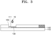
FIG. 3 is an internal cross-sectional view of a strip according to an embodiment; -
FIG. 4 is a view of a potassium ion selective membrane according to an embodiment; -
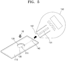
FIG. 5 is a view of a strip and a measuring device according to an embodiment; -
FIG. 6 is a plan view of a strip according to another embodiment; -
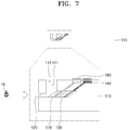
FIG. 7 is an internal cross-sectional view of a strip according to another embodiment; -
FIG. 8 is a plan view of a strip when a reference electrode is included in the strip according to another embodiment; -
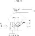
FIG. 9 is an internal cross-sectional view of a strip when a reference electrode is included in the strip according to another embodiment; and -
FIG. 10 is a view of a first working electrode contact portion and a reference electrode contact portion according to another embodiment. - One or more embodiments relate to a strip structure for potassium ion measurement capable of simply measuring potassium ions in the body in a short time by using a strip including a potassium ion selective membrane and a working electrode. Hereinafter, embodiments of the present disclosure will be described in detail with reference to the accompanying drawings.
- A
solution 10 that may be used in the embodiments may be blood or urine. However, the present disclosure is not limited thereto, and thesolution 10 may be a specific solution containing potassium. -
FIG. 1 is a view of a method of measuring the concentration of potassium ions through a reference electrode and a working electrode. Referring toFIG. 1 , when thesolution 10 containing potassium ions is sufficiently dropped on astrip 110, thesolution 10 enters a potassium ionselective permeation membrane 130 for a certain period of time, whereby only potassium ions may be selectively filtered. - Here, the potassium ion
selective membrane 130 covers a workingelectrode 140, and the workingelectrode 140 is brought into contact with thesolution 10 in which only potassium ions are selectively filtered. Areference electrode 151 is located near the potassium ionselective membrane 130 and is in contact with thesolution 10 before being filtered through the potassium ionselective permeation membrane 130. - By using the potassium ion
selective membrane 130 as described above, potential (V) varies depending on the concentration of potassium in thereference electrode 151 and the workingelectrode 140, and the concentration of potassium ions of thesolution 10 may be measured by detecting the potential (V). -
FIG. 1 schematically shows a method of measuring the concentration of potassium ions through thestrip 110 and thereference electrode 151 including the workingelectrode 140 and the potassium ionselective membrane 130. According to an embodiment, thereference electrode 151 may be included in ameasuring device 150, which is separated from thestrip 110. Also, thereference electrode 151 may be included in thestrip 110 if necessary. Hereinafter, embodiments of the present disclosure will be described in detail - Referring to
FIGS. 2 and3 , a strip structure for measuring potassium ions according to an embodiment may include thestrip 110, aninlet 120, the potassium ionselective membrane 130, and the first workingelectrode 140. - Referring to
FIG. 2 , thestrip 110 has aninner space 111 for receiving thesolution 10 therein, and may be formed in a plate shape. Thestrip 110 may include polydimethylsiloxane (PDMS), which may be a disposable strip. - The
strip 110 has theinner space 111 for receiving thesolution 10 therein, and the potassium ionselective membrane 130 and the first workingelectrode 140 may be arranged in theinner space 111. When thesolution 10 is dropped into theinner space 111, thesolution 10 may be brought into contact with the first workingelectrode 140 after passing through the potassium ionselective membrane 130 in theinner space 111. - As will be described later below, the
strip 110 may be inserted into the measuringdevice 150 and used for disposable use. Since thestrip 110 is used for disposable use, it is possible to easily measure the concentration of potassium ions in the body and the accuracy may be improved because it is not reused. - The
inlet 120 is formed in thestrip 110 and is an entrance through which thesolution 10 may be injected into theinner space 111 of thestrip 110. Theinlet 120 is communicated with theinner space 111, and when thesolution 10 is injected through theinlet 120, thesolution 10 may be injected into theinner space 111 through theinlet 120. - The
inlet 120 may be a circular hole in an upper surface of thestrip 110, but is not limited thereto. Theinlet 120 may be arranged at various points as long as theinlet 120 can communicate with theinner space 111 and inject thesolution 10 into theinner space 111. As will be described later below, theinlet 120 may be arranged on a side surface of thestrip 110 and theinlet 120 may be a thin tube (capillary) having a diameter less than a diameter of theinner space 111 to utilize a capillary phenomenon. - The potassium ion
selective membrane 130 is arranged in theinner space 111 and is capable of permeating potassium ions of thesolution 10. The potassium ionselective membrane 130 is selectively permeable to potassium ions. Thesolution 10 injected through theinlet 120 is injected into theinner space 111 and passes through the potassium ionselective membrane 130. - The potassium ion
selective membrane 130 may include cellulose acetate and may be made of a natural polymer-derived material. In more detail, cellulose acetate including valinomycin may be used. As described above, thestrip 110 may be discarded after one use. Therefore, the potassium ionselective membrane 130 is preferably made of a natural material which is inexpensive and is decomposed quickly when it is discarded. - Referring to
FIG. 4 , the potassium ionselective membrane 130 may also be a double membrane. In more detail, the potassium ionselective membrane 130 may include aprotective membrane 132 and amembrane 131. - The
protective membrane 132 is formed with pores through a method such as electrospinning and is capable of filtering thesolution 10 through the pores. Theprotective membrane 132 protects the potassium ionselective membrane 130 and is an area where thesolution 10 containing potassium ions may be collected. - The
membrane 131 includesvalinomycin 133 as a substance with ion transport ability and may selectively filter only potassium ions in theprotective membrane 132 through thevalinomycin 133. That is, in thesolution 10 containing potassium in theprotective membrane 132, only potassium ions are selectively filtered by themembrane 131, thereby separating potassium ions. Themembrane 131 may be a PVC membrane or may be a cellulose acetate membrane. - The
first working electrode 140 extends in a strip shape, wherein one side of the first workingelectrode 140 is arranged inside the potassium ionselective membrane 130 and the other side of the first workingelectrode 140 is on a surface of thestrip 110. The inside of the potassium ionselective membrane 130 refers to an area where thesolution 10 is permeated through the potassium ionselective membrane 130. - In more detail, referring to
FIG. 3 , the direction toward theinlet 120 may be an outer side and the opposite direction may be an inner side with the potassium ionselective membrane 130 provided in theinner space 111 as a center. One side of the first workingelectrode 140 is arranged inside the potassium ionselective membrane 130, and is brought into contact with a portion that selectively permeates only potassium ions. - The
first working electrode 140 may extend in a strip shape and may extend from the inside of the potassium ionselective membrane 130 to the surface of thestrip 110. As shown inFIG. 3 , the other side of the first workingelectrode 140 is preferably arranged in the surface of thestrip 110 so as to be exposed to the outside of thestrip 110. - As will be described later below, the
strip 110 is inserted into the measuringdevice 150 so that the measuringdevice 150 may measure potassium ions using thereference electrode 151 included in themeasuring device 150. Since the concentration of potassium ions may be measured only when the first workingelectrode 140 is brought into contact with the measuringdevice 150 when thestrip 110 is inserted into the measuringdevice 150, the first workingelectrode 140 needs to be exposed to the outside of thestrip 110. Therefore, the other side of the first workingelectrode 140 is preferably arranged in the surface of thestrip 110. - Referring to
FIG. 5 , a strip structure for measuring potassium ions according to an embodiment may further include the measuringdevice 150 that may include thereference electrode 151 and aninlet 152 into which thestrip 110 may be inserted. The measuringdevice 150 is separated from thestrip 110 and may measure potassium ions by inserting thestrip 110 into theinlet 152 of the measuringdevice 150. - By separating the
strip 110 including the first workingelectrode 140 and the measuringdevice 150 including thereference electrode 151 and using thestrip 110 as a disposable one, a user may easily measure potassium ions in a short time and may easily use themeasuring device 150 in a normal home. - (The
reference electrode 151 shown inFIG. 2 represents thereference electrode 151 included in themeasuring device 150, not in thestrip 110. Thereference electrode 151 shown inFIG. 2 indicates a position where thereference electrode 151 is arranged when thestrip 110 is inserted into the measuringdevice 150.) - Referring to
FIG. 5 , the measuringdevice 150 includes thereference electrode 151, and thereference electrode 151 may include platinum (Pt) or silver chloride (AgCl). Theinlet 152 of the measuringdevice 150, which is a hole for inserting thestrip 110 into the measuringdevice 150, may be formed in a shape corresponding to the shape of thestrip 110. - When the
strip 110 is inserted into the measuringdevice 150 through theinlet 152, thereference electrode 151 may be inserted into theinner space 111. Here, thereference electrode 151 is arranged outside the potassium ionselective membrane 130. - That is, the first working
electrode 140 is arranged inside the potassium ionselective membrane 130, and thereference electrode 151 is arranged outside the potassium ionselective membrane 130. Since thesolution 10 inside passes through the potassium ionselective membrane 130, a difference in the concentration of potassium ions occurs between the inside and the outside. The concentration of potassium ions in thesolution 10 may be measured by measuring a voltage difference V caused by the concentration difference through thereference electrode 151 and the first workingelectrode 140. - According to another embodiment, the
inlet 120 may be formed on a side surface of thestrip 110. Referring toFIGS. 6 and7 , theinlet 120 may be formed on the side surface of thestrip 110, not on an upper surface thereof. Theinlet 120 may include a capillary (thin tube) having a diameter less than a diameter of theinner space 111, and a capillary phenomenon may be used. - In more detail, when the
solution 10 is injected into theinlet 120, even a small amount of thesolution 10 may be easily injected into theinlet 120 by the capillary phenomenon. Theinlet 120 may be formed of a plurality of capillaries, and theinlet 120 may be formed of porous (including the plurality of capillaries) holes. - According to another embodiment, the first working
electrode 140 may extend obliquely with respect to a direction in which thestrip 110 extends in a longitudinal direction. Thefirst working electrode 140 may extend in a direction parallel to the longitudinal direction of thestrip 110 as shown inFIG. 3 . However, as shown inFIG. 7 , it is preferable that the first workingelectrode 140 extends upward and obliquely with respect to the direction in which thestrip 110 extends in a longitudinal direction. (Here, the longitudinal direction of thestrip 110 may be a horizontal direction in thestrip 110 in a plate shape, and a vertical direction may be a width direction.) - As such, extending the first working
electrode 140 obliquely with respect to the direction in which thestrip 110 extends in a longitudinal direction is to form the potassium ionselective membrane 130 which may be arranged on the first workingelectrode 140. The potassium ionselective membrane 130 may be arranged on the first workingelectrode 140 in the form of a solution and then dried. - When the first working
electrode 140 is arranged only in a direction parallel to the longitudinal direction of thestrip 110, the potassium ionselective membrane 130 in the form of a solution continues to flow along the first workingelectrode 140 so that the potassium ionselective membrane 130 may not be formed exactly at a desired position. - However, when the first working
electrode 140 extends upward and obliquely with respect to the direction in which thestrip 110 extends in a longitudinal direction as shown inFIG. 7 , a clogging space may be formed through the first workingelectrode 140. This allows the potassium ionselective membrane 130 in the form of a solution to be dried without flowing, and the potassium ionselective membrane 130 may be accurately positioned at a desired position. - A strip structure for measuring potassium ions according to another embodiment may further include a
blood filter membrane 170 in theinner space 111 and capable of removing foreign matter of thesolution 10, wherein one side of an electrode extending in a strip shape may be arranged inside theblood filter membrane 170 and the other side of the electrode may further include asecond working electrode 160 arranged on a surface of thestrip 110. - Referring to
FIG. 7 , theblood filter membrane 170 is arranged outside the potassium ionselective membrane 130 so that theblood filter membrane 170 may filter large-sized substances such as leukocytes, red blood cells, and the like in the blood before the potassium ionselective membrane 130 filters thesolution 10. - When the
solution 10 has large-sized substances, the efficiency of selectively passing potassium ions through the potassium ionselective membrane 130 is reduced. In order to prevent such a problem, theblood filter membrane 170 filters thesolution 10 first, thereby measuring a more accurate concentration of potassium ions. - The fact that the
blood filter membrane 170 is arranged outside the potassium ionselective membrane 130 means that theblood filter membrane 170 may be arranged between theinlet 120 and the potassium ionselective membrane 130. As a result, theblood filter membrane 170 is arranged closer to theinlet 120 than the potassium ionselective membrane 130 so that theblood filter membrane 170 may filter thesolution 10 first. - One end of the second working
electrode 160 extending in a strip shape is inside theblood filter membrane 170 and the other end is in the surface of thestrip 110. In more detail, the second workingelectrode 160 may be between theblood filter membrane 170 and the potassium ionselective membrane 130 and may be provided to measure other specific materials after filtering thesolution 10 into theblood filter membrane 170. In more detail, the second workingelectrode 160 may measure a substance that may pass through theblood filter membrane 170. - The measuring
device 150 may be used to measure other specific materials through the second workingelectrode 160 and other specific materials may be measured while thestrip 110 is inserted into the measuringdevice 150. (Here, a separate second reference electrode may be included in themeasuring device 150.) Therefore, the second workingelectrode 160 needs to be exposed to the outside of thestrip 110 in the same manner as the first workingelectrode 140 so that the other side of the second workingelectrode 160 is preferably in the surface of thestrip 110. - Referring to
FIG. 7 , it is preferable that the second workingelectrode 160 extends upward and obliquely with respect to the direction in which thestrip 110 extends in a longitudinal direction in the same manner as the first workingelectrode 140. This is for forming theblood filter membrane 170 which may be on the second workingelectrode 160. - The
blood filter membrane 170 may be arranged on the second workingelectrode 160 in the form of a solution and then dried. When the second workingelectrode 160 is arranged only in a direction parallel to the longitudinal direction of thestrip 110, theblood filter membrane 170 in the form of a solution continues to flow along the second workingelectrode 160 so that theblood filter membrane 170 may not be formed exactly at a desired position. - However, when the second working
electrode 160 extends upward and obliquely with respect to the direction in which thestrip 110 extends in a longitudinal direction as shown inFIG. 7 , a clogging space may be formed through the second workingelectrode 160. This allows theblood filter membrane 170 in the form of a solution to be dried without flowing, and theblood filter membrane 170 may be accurately positioned at a desired position. - According to an embodiment, the second working
electrode 160 may be used to measure other specific materials in thesolution 10 and may be omitted if necessary. - According to an embodiment, the
strip 110 may include aninsertion hole 112 in the surface of thestrip 110 and communicating with theinner space 111. Theinsertion hole 112 is a hole into which thereference electrode 151 of the measuringdevice 150 may be inserted when thestrip 110 is inserted into the measuringdevice 150, wherein thereference electrode 151 is placed in theinner space 111 through theinsertion hole 112. (Here, as described above, thereference electrode 151 may be arranged outside the potassium ionselective membrane 130.) - A strip structure for potassium ion measurement according to the embodiment described above may be operated as follows. First, the
solution 10 is inserted into theinner space 111 through theinlet 120. Theinlet 120 may be arranged on the upper surface of thestrip 110 or may be arranged on a side surface of thestrip 110. - The
inlet 120 is preferably made of a capillary having a diameter less than the diameter of theinner space 111 and a small amount of thesolution 10 may be injected into theinner space 111 by a capillary phenomenon through theinlet 120. - When a sufficient amount of the
solution 10 is injected into theinner space 111, potassium ions in thesolution 10 pass through the potassium ionselective membrane 130 for a certain period of time, and a difference in the concentration of potassium ions occurs between the inside and the outside of the potassium ionselective membrane 130. (The outside is a direction toward theinlet 120 with the potassium ionselective membrane 130 as a center, and the inside is the opposite direction.) - Thereafter, when the
strip 110 is inserted through theinlet 152 of the measuringdevice 150, thereference electrode 151 of the measuringdevice 150 is arranged outside the potassium ionselective membrane 130. - The voltage difference V is generated due to a difference in the concentration of potassium ions between an inner side and an outer side of the potassium ion
selective membrane 130. Thereference electrode 151 arranged outside the potassium ionselective membrane 130 and the first workingelectrode 140 arranged inside the potassium ionselective membrane 130 may detect the concentration of potassium ions by measuring the voltage difference V. - The strip structure for potassium ion measurement according to the embodiment described above may be modified and used as follows.
- Referring to
FIGS. 8 and9 , thereference electrode 151 included in themeasuring device 150 may be included in thestrip 110. That is, thereference electrode 151 may be included in themeasuring device 150 or may be included in thestrip 110. - In more detail, according to another embodiment, as shown in
FIGS. 8 and9 , thereference electrode 151 may be formed on thestrip 110 instead of the measuringdevice 150. Thereference electrode 151 extends in a strip shape, and one side of thereference electrode 151 is arranged outside the potassium ionselective membrane 130 and the other side of thereference electrode 151 is in the surface of thestrip 110. - In this case, the
reference electrode 151 is not included in themeasuring device 150, and only a device capable of measuring the potential (V) is formed in themeasuring device 150. - One side of the
reference electrode 151 may be arranged on the outer side of the potassium ionselective membrane 130 and further on the outermost side of the potassium ionselective membrane 130. When the second workingelectrode 160 and theblood filter membrane 170 are used, thereference electrode 151 may be arranged outside the second workingelectrode 160 and theblood filter membrane 170. - When the
reference electrode 151 is included in thestrip 110, thereference electrode 151 also needs to be exposed to the outside of thestrip 110 in the same manner as the first workingelectrode 140 and the second workingelectrode 160. Therefore, the other side of thereference electrode 151 is preferably arranged in the surface of thestrip 110. Furthermore, referring toFIGS. 8 and9 , it is also preferable that thereference electrode 151 extends upward and obliquely with respect to the direction in which thestrip 110 extends in a longitudinal direction. - The
reference electrode 151 may be formed by depositing a material that can be used as thereference electrode 151 such as silver chloride (AgCl) according to the shape of thestrip 110. A method of inserting thestrip 110 after forming thereference electrode 151 using an Ag film is also possible. - Referring to
FIG. 9 , a gap between the first workingelectrode 140 and the potassium ionselective membrane 130 of the strip structure for measuring potassium ions according to the embodiment may be filled with anelectrolytic material 180 which dissociates into ions and causes a current to flow. In more detail, theelectrolytic material 180 may be in a solution state or a gel state, and theelectrolytic material 180 may be a hydrogel. (Theelectrolytic material 180 is not limited to the hydrogel, and various materials may be used as long as they dissociate into ions and cause a current to flow.) - By filling the gap between the first working
electrode 140 and the potassium ionselective membrane 130 with theelectrolytic material 180 as described above, the accuracy of sensing potassium ions in the blood is increased. Accordingly, the potassium ions in the blood may be accurately measured. Furthermore, referring toFIG. 9 , a gap between the second workingelectrode 160 and theblood filter membrane 170 may also be filled with theelectrolytic material 180 which dissociates into ions and causes a current to flow. - Referring to
FIG. 10 , a strip structure for measuring potassium ions according to an embodiment may be modified and used as follows. Thefirst working electrode 140 and thereference electrode 151 may be formed at theinlet 120 of thestrip 110 with a first workingelectrode contact portion 140a and a referenceelectrode contact portion 151 a having a surface area greater than the width of the first workingelectrode 140 and thereference electrode 151 having a strip shape. - The first working
electrode contact portion 140a and the referenceelectrode contact portion 151a may be formed through a metal deposition method. When the first workingelectrode contact portion 140a and the referenceelectrode contact portion 151a are formed, a contact area between thesolution 10 injected through theinlet 120 and the first workingelectrode 140 and thereference electrode 151 may be widened. - The first working
electrode contact portion 140a and the referenceelectrode contact portion 151a may be formed in various shapes as long as the contact area of thesolution 10 with the first workingelectrode 140 and thereference electrode 151 may be widened. - For example, the first working
electrode contact portion 140a may have a circular shape at theinlet 120 and the referenceelectrode contact portion 151a may have an eyebrow shape. However, the present disclosure is not limited thereto. - As shown in
FIG. 10 , when the first workingelectrode contact portion 140a and the referenceelectrode contact portion 151a are formed in the first workingelectrode 140 and thereference electrode 151, the first workingelectrode 140 and thereference electrode 151 may be stacked and arranged on thestrip 110. - For example, the reference
electrode contact portion 151a, the first workingelectrode contact portion 140a, the potassium ionselective membrane 130, and theblood filter membrane 170 may be stacked and arranged on theinlet 120. The referenceelectrode contact portion 151a is arranged in theinlet 120 and theblood filter membrane 170 is arranged under the referenceelectrode contact portion 151a. The potassium ionselective membrane 130 may be arranged under theblood filter membrane 170 and the first workingelectrode contact portion 140a may be arranged under the potassium ionselective membrane 130. - That is, according to another embodiment, when the first working
electrode 140 and thereference electrode 151 are stacked and arranged on thestrip 110, the referenceelectrode contact portion 151a, theblood filter membrane 170, the potassium ionselective membrane 130, and the first workingelectrode contact portion 140a may be stacked and arranged on theinlet 120. - Thus, foreign matter of blood may be removed through the
blood filter membrane 170 while widening the contact area of thesolution 10 with the first workingelectrode 140 and thereference electrode 151, and the potassium concentration of the blood may be measured through the reference electrode 151-the potassium ion selective membrane 130-the first workingelectrode 140. - The strip structure for potassium ion measurement according to the embodiment described above has the following effects.
- Conventionally, in order to measure the potassium concentration in the body, it takes a lot of time to visit a hospital or a medical examination center to conduct a blood test, an electrocardiogram examination, and the like. However, the strip structure for measuring potassium ions according to the embodiment of the present disclosure may easily measure the potassium concentration in the body any time through the measuring
device 150 capable of measuring a voltage and thestrip 110 used as a disposable. - In more detail, according to the strip structure for measuring potassium ions according to the embodiment of the present disclosure, a user may easily measure the potassium concentration at home without visiting the hospital or the medical examination center by separating the
strip 110 including the first workingelectrode 140 and the measuringdevice 150 including thereference electrode 151 and by using thestrip 110 as a disposable. - Furthermore, in the past, since the blood test and the electrocardiogram examination have been performed to measure the potassium concentration in the body, the examination procedure is complicated and time-consuming. However, the strip structure for measuring potassium ions according to the embodiment of the present disclosure has an advantage that the potassium ions in the body may be simply measured by dropping the
solution 10 on thestrip 110 using the potassium ionselective membrane 130 and the first workingelectrode 140. - Furthermore, the conventional device for measuring potassium concentration in the body is difficult to carry and use at home because it is large. However, the strip structure for measuring potassium ions according to the embodiment of the present invention is compatible with the
strip 110 which may be used as a disposable, and thus the measuringdevice 150 capable of measuring voltage may be manufactured in a small size and may be easily used. - This allows a patient who needs to constantly manage the potassium concentration in the body to monitor the potassium concentration any time while measuring the potassium concentration at home quickly and easily.
- According to the strip structure for measuring potassium ions according to one or more embodiments, the concentration of potassium in the body may be easily measured at all times through a measuring device capable of measuring voltage and a disposable strip, and the concentration of potassium in the body may also be easily measured by a method for dropping a solution on a strip using a potassium ion selective membrane and a first working electrode.
- It should be understood that embodiments described herein should be considered in a descriptive sense only and not for purposes of limitation. Descriptions of features or aspects within each embodiment should typically be considered as available for other similar features or aspects in other embodiments.
- While one or more embodiments have been described with reference to the figures, it will be understood by those of ordinary skill in the art that various changes in form and details may be made therein without departing from the spirit and scope of the disclosure as defined by the following claims.
Claims (11)
- A strip structure for measuring potassium ions, the strip structure comprising:a strip having an inner space for receiving a solution therein and being formed in a plate shape;an inlet formed in the strip and capable of injecting a solution into the inner space of the strip;a potassium ion selective membrane arranged in the inner space and capable of permeating potassium ions of the solution; anda first working electrode extending in a strip shape, wherein one side of the first working electrode is arranged inside the potassium ion selective membrane and the other side of the first working electrode is on a surface of the strip.
- The strip structure of claim 1, further comprising:a measuring device comprising a reference electrode and an inlet into which the strip is inserted,wherein the measuring device is separated from the strip and measures potassium ions by inserting the strip into the inlet of the measuring device.
- The strip structure of claim 1, wherein the first working electrode extends upward and obliquely with respect to a direction in which the strip extends in a longitudinal direction.
- The strip structure of claim 1, further comprising:a blood filter membrane arranged in the inner space and capable of removing foreign matter of the solution; anda second working electrode extending in a strip shape, wherein one side of the second working electrode is arranged inside the potassium ion selective membrane and the other side of the second working electrode is in the surface of the strip,wherein the blood filter membrane is arranged between the inlet and the potassium ion selective membrane, andone side of the second working electrode is between the blood filter membrane and the potassium ion selective membrane.
- The strip structure of claim 4, wherein the second working electrode extends upward and obliquely with respect to a direction in which the strip extends in a longitudinal direction.
- The strip structure of claim 1, wherein the inlet comprises a capillary having a diameter less than a diameter of the inner space.
- The strip structure of claim 6, wherein the inlet comprises a plurality of capillaries.
- The strip structure of claim 1, wherein the potassium ion selective membrane comprises cellulose acetate.
- The strip structure of claim 2, wherein the strip comprises an insertion hole arranged in the surface of the strip and communicating with the inner space, and
the reference electrode of the measuring device is inserted into the insertion hole when the strip is inserted into the measuring device. - The strip structure of claim 1, further comprising:
a reference electrode extending in a strip shape, wherein one side of the reference electrode is arranged outside the potassium ion selective membrane and the other side of the reference electrode is in the surface of the strip. - The strip structure of claim 1, wherein a gap between the first working electrode and the potassium ion selective membrane is filled with an electrolytic material.
Applications Claiming Priority (1)
| Application Number | Priority Date | Filing Date | Title |
|---|---|---|---|
| KR1020180163318A KR102169586B1 (en) | 2018-12-17 | 2018-12-17 | Strip structure for measuring potassium ions |
Publications (2)
| Publication Number | Publication Date |
|---|---|
| EP3671198A1 true EP3671198A1 (en) | 2020-06-24 |
| EP3671198B1 EP3671198B1 (en) | 2025-07-23 |
Family
ID=68887242
Family Applications (1)
| Application Number | Title | Priority Date | Filing Date |
|---|---|---|---|
| EP19215501.8A Active EP3671198B1 (en) | 2018-12-17 | 2019-12-12 | Strip structure for measuring potassium ions |
Country Status (5)
| Country | Link |
|---|---|
| US (1) | US11525801B2 (en) |
| EP (1) | EP3671198B1 (en) |
| JP (1) | JP6861443B2 (en) |
| KR (1) | KR102169586B1 (en) |
| CN (1) | CN111474334B (en) |
Families Citing this family (2)
| Publication number | Priority date | Publication date | Assignee | Title |
|---|---|---|---|---|
| KR20220116634A (en) | 2021-02-15 | 2022-08-23 | 주식회사 더도니 | Sensor that detects the physical quantity of a specific component in a solution and the method how to use the seonsor |
| KR102757781B1 (en) | 2024-03-22 | 2025-01-21 | 주식회사 더도니 | Strips for measuring blood sugar and potassium |
Citations (6)
| Publication number | Priority date | Publication date | Assignee | Title |
|---|---|---|---|---|
| US3753887A (en) * | 1969-06-04 | 1973-08-21 | Hydronautics | Alkali metal specific measuring electrode |
| US6663756B2 (en) * | 2000-10-19 | 2003-12-16 | I-Sens Inc. | Microchip-type oxygen gas sensor based on differential potentiometry |
| US20100147688A1 (en) * | 2006-01-19 | 2010-06-17 | Mohamed Roshdy Soliman El Hadidy | 2-in-1 biochip |
| CN102636532A (en) * | 2012-04-24 | 2012-08-15 | 南京工业大学 | Medical all-solid-state potassium ion selective sensor and preparation method thereof |
| US20130168247A1 (en) * | 2011-12-28 | 2013-07-04 | Horiba, Ltd. | Ion analyzer |
| US20140105788A1 (en) * | 2012-10-11 | 2014-04-17 | Horiba, Ltd. | Multi-ion sensor |
Family Cites Families (14)
| Publication number | Priority date | Publication date | Assignee | Title |
|---|---|---|---|---|
| US4171246A (en) * | 1976-05-19 | 1979-10-16 | Eastman Kodak Company | Method for determining ionic activity of components of liquid drops |
| US4713165A (en) * | 1986-07-02 | 1987-12-15 | Ilex Corporation | Sensor having ion-selective electrodes |
| JPH04339251A (en) | 1991-05-15 | 1992-11-26 | Tokuyama Soda Co Ltd | Potassium ion selective composition |
| JPH06229973A (en) * | 1993-01-29 | 1994-08-19 | Kyoto Daiichi Kagaku:Kk | Current detection type dry ion selective electrode |
| US5421983A (en) * | 1993-11-12 | 1995-06-06 | E. I. Du Pont De Nemours And Company | Anion selective electrodes containing fumed silica |
| JP2001159618A (en) | 1999-12-03 | 2001-06-12 | Matsushita Electric Ind Co Ltd | Biosensor |
| JP4601809B2 (en) | 2000-12-11 | 2010-12-22 | パナソニック株式会社 | Biosensor and substrate measurement method |
| US6960466B2 (en) | 2001-05-31 | 2005-11-01 | Instrumentation Laboratory Company | Composite membrane containing a cross-linked enzyme matrix for a biosensor |
| KR100885074B1 (en) | 2007-07-26 | 2009-02-25 | 주식회사 아이센스 | Microfluidic Sensor Complex Structure |
| US20180338713A1 (en) * | 2013-11-11 | 2018-11-29 | Sandia Corporation | Integrated fluidic chip for transdermal sensing of physiological markers |
| JP6404049B2 (en) * | 2014-09-18 | 2018-10-10 | 株式会社日立ハイテクノロジーズ | Flow path integrated sensor |
| RU2017134295A (en) * | 2015-05-18 | 2019-04-03 | Сименс Хелткэа Дайагностикс Инк. | ADVANCED CHLORIDE-SELECTIVE MEMBRANE |
| US20180164243A1 (en) | 2015-06-05 | 2018-06-14 | Nitto Denko Corporation | Biosensor chip and biosensor device |
| KR101756133B1 (en) * | 2015-12-04 | 2017-07-10 | 계명대학교 산학협력단 | PORTABLE SMART URINE SODIUM(Na) AND POTASSIUM(K) DIGITAL MEASURING INSTRUMENT USING ELECTRICAL IMPEDANCE MEASURING METHOD AND METHOD THEREOF |
-
2018
- 2018-12-17 KR KR1020180163318A patent/KR102169586B1/en active Active
-
2019
- 2019-12-09 US US16/707,263 patent/US11525801B2/en active Active
- 2019-12-12 EP EP19215501.8A patent/EP3671198B1/en active Active
- 2019-12-13 JP JP2019225348A patent/JP6861443B2/en active Active
- 2019-12-16 CN CN201911291274.XA patent/CN111474334B/en active Active
Patent Citations (6)
| Publication number | Priority date | Publication date | Assignee | Title |
|---|---|---|---|---|
| US3753887A (en) * | 1969-06-04 | 1973-08-21 | Hydronautics | Alkali metal specific measuring electrode |
| US6663756B2 (en) * | 2000-10-19 | 2003-12-16 | I-Sens Inc. | Microchip-type oxygen gas sensor based on differential potentiometry |
| US20100147688A1 (en) * | 2006-01-19 | 2010-06-17 | Mohamed Roshdy Soliman El Hadidy | 2-in-1 biochip |
| US20130168247A1 (en) * | 2011-12-28 | 2013-07-04 | Horiba, Ltd. | Ion analyzer |
| CN102636532A (en) * | 2012-04-24 | 2012-08-15 | 南京工业大学 | Medical all-solid-state potassium ion selective sensor and preparation method thereof |
| US20140105788A1 (en) * | 2012-10-11 | 2014-04-17 | Horiba, Ltd. | Multi-ion sensor |
Also Published As
| Publication number | Publication date |
|---|---|
| KR20200074665A (en) | 2020-06-25 |
| US11525801B2 (en) | 2022-12-13 |
| KR102169586B1 (en) | 2020-10-23 |
| CN111474334A (en) | 2020-07-31 |
| JP6861443B2 (en) | 2021-04-21 |
| EP3671198B1 (en) | 2025-07-23 |
| CN111474334B (en) | 2022-05-27 |
| US20200191741A1 (en) | 2020-06-18 |
| JP2020098208A (en) | 2020-06-25 |
Similar Documents
| Publication | Publication Date | Title |
|---|---|---|
| CN110996795B (en) | biological fluid collection device | |
| CA2494090C (en) | Apparatus and method for analytical determinations | |
| US4844871A (en) | Method of determining the partial pressure of gases in blood and an apparatus for performing the method | |
| US9689839B2 (en) | Method and apparatus for sensing ion concentrations in a fluid sample | |
| EP3665479B1 (en) | Apparatus for accurate sensing of physiological substance in blood | |
| Koutsouris et al. | Determination of erythrocyte transit times through micropores. I-Basic operational principles | |
| CN110740812A (en) | Biological fluid separation device | |
| US20100160758A1 (en) | In vivo component measurement method and in vivo component measurement apparatus | |
| US11525801B2 (en) | Strip structure for measuring potassium ions | |
| JP2019532809A (en) | Method for determining the permeation characteristics of hollow fiber membranes | |
| SE1650130A1 (en) | An arrangement for collection and separation of a body fluid for purposes of analysis and a method relating thereto | |
| US7790438B2 (en) | Apparatuses and methods for detecting an analyte | |
| KR102024995B1 (en) | Blood analyzer and method for blood analysis using the same | |
| CA1138757A (en) | Method and apparatus for analysing liquid | |
| KR20190117411A (en) | Blood analyzer and method for blood analysis using the same | |
| JPH02170041A (en) | Measuring apparatus for detecting chemical | |
| KR100900655B1 (en) | Blood test apparatus having inhalation blood collection device to keep blood collection constant | |
| Leblond et al. | Evaluation of a simplified filtration technique for the routine measurement of erythrocyte deformability | |
| RU138749U1 (en) | DEVICE FOR EVALUATING THE ELECTROLYTE DIFFUSION SPEED THROUGH DENTAL TUBES | |
| RU2672354C2 (en) | Method for continuous monitoring of analyte content in blood | |
| DE19942898B4 (en) | dialysis probe | |
| JPH0252220B2 (en) | ||
| KR20230051422A (en) | Systems for capturing and detecting species present in biological fluids |
Legal Events
| Date | Code | Title | Description |
|---|---|---|---|
| PUAI | Public reference made under article 153(3) epc to a published international application that has entered the european phase |
Free format text: ORIGINAL CODE: 0009012 |
|
| STAA | Information on the status of an ep patent application or granted ep patent |
Free format text: STATUS: REQUEST FOR EXAMINATION WAS MADE |
|
| 17P | Request for examination filed |
Effective date: 20191212 |
|
| AK | Designated contracting states |
Kind code of ref document: A1 Designated state(s): AL AT BE BG CH CY CZ DE DK EE ES FI FR GB GR HR HU IE IS IT LI LT LU LV MC MK MT NL NO PL PT RO RS SE SI SK SM TR |
|
| AX | Request for extension of the european patent |
Extension state: BA ME |
|
| STAA | Information on the status of an ep patent application or granted ep patent |
Free format text: STATUS: EXAMINATION IS IN PROGRESS |
|
| 17Q | First examination report despatched |
Effective date: 20220826 |
|
| RAP1 | Party data changed (applicant data changed or rights of an application transferred) |
Owner name: THEDONEE INC. |
|
| GRAP | Despatch of communication of intention to grant a patent |
Free format text: ORIGINAL CODE: EPIDOSNIGR1 |
|
| STAA | Information on the status of an ep patent application or granted ep patent |
Free format text: STATUS: GRANT OF PATENT IS INTENDED |
|
| INTG | Intention to grant announced |
Effective date: 20241111 |
|
| GRAS | Grant fee paid |
Free format text: ORIGINAL CODE: EPIDOSNIGR3 |
|
| GRAA | (expected) grant |
Free format text: ORIGINAL CODE: 0009210 |
|
| STAA | Information on the status of an ep patent application or granted ep patent |
Free format text: STATUS: THE PATENT HAS BEEN GRANTED |
|
| AK | Designated contracting states |
Kind code of ref document: B1 Designated state(s): AL AT BE BG CH CY CZ DE DK EE ES FI FR GB GR HR HU IE IS IT LI LT LU LV MC MK MT NL NO PL PT RO RS SE SI SK SM TR |
|
| REG | Reference to a national code |
Ref country code: GB Ref legal event code: FG4D |
|
| REG | Reference to a national code |
Ref country code: CH Ref legal event code: EP |
|
| REG | Reference to a national code |
Ref country code: IE Ref legal event code: FG4D |
|
| REG | Reference to a national code |
Ref country code: DE Ref legal event code: R096 Ref document number: 602019072841 Country of ref document: DE |
|
| REG | Reference to a national code |
Ref country code: NL Ref legal event code: MP Effective date: 20250723 |
|
| PG25 | Lapsed in a contracting state [announced via postgrant information from national office to epo] |
Ref country code: PT Free format text: LAPSE BECAUSE OF FAILURE TO SUBMIT A TRANSLATION OF THE DESCRIPTION OR TO PAY THE FEE WITHIN THE PRESCRIBED TIME-LIMIT Effective date: 20251124 |
|
| PG25 | Lapsed in a contracting state [announced via postgrant information from national office to epo] |
Ref country code: NL Free format text: LAPSE BECAUSE OF FAILURE TO SUBMIT A TRANSLATION OF THE DESCRIPTION OR TO PAY THE FEE WITHIN THE PRESCRIBED TIME-LIMIT Effective date: 20250723 |
|
| REG | Reference to a national code |
Ref country code: AT Ref legal event code: MK05 Ref document number: 1816895 Country of ref document: AT Kind code of ref document: T Effective date: 20250723 |
|
| PG25 | Lapsed in a contracting state [announced via postgrant information from national office to epo] |
Ref country code: IS Free format text: LAPSE BECAUSE OF FAILURE TO SUBMIT A TRANSLATION OF THE DESCRIPTION OR TO PAY THE FEE WITHIN THE PRESCRIBED TIME-LIMIT Effective date: 20251123 |
|
| PG25 | Lapsed in a contracting state [announced via postgrant information from national office to epo] |
Ref country code: NO Free format text: LAPSE BECAUSE OF FAILURE TO SUBMIT A TRANSLATION OF THE DESCRIPTION OR TO PAY THE FEE WITHIN THE PRESCRIBED TIME-LIMIT Effective date: 20251023 |
|
| REG | Reference to a national code |
Ref country code: LT Ref legal event code: MG9D |
|
| PG25 | Lapsed in a contracting state [announced via postgrant information from national office to epo] |
Ref country code: AT Free format text: LAPSE BECAUSE OF FAILURE TO SUBMIT A TRANSLATION OF THE DESCRIPTION OR TO PAY THE FEE WITHIN THE PRESCRIBED TIME-LIMIT Effective date: 20250723 |
|
| PG25 | Lapsed in a contracting state [announced via postgrant information from national office to epo] |
Ref country code: FI Free format text: LAPSE BECAUSE OF FAILURE TO SUBMIT A TRANSLATION OF THE DESCRIPTION OR TO PAY THE FEE WITHIN THE PRESCRIBED TIME-LIMIT Effective date: 20250723 |
|
| PG25 | Lapsed in a contracting state [announced via postgrant information from national office to epo] |
Ref country code: HR Free format text: LAPSE BECAUSE OF FAILURE TO SUBMIT A TRANSLATION OF THE DESCRIPTION OR TO PAY THE FEE WITHIN THE PRESCRIBED TIME-LIMIT Effective date: 20250723 |
|
| PG25 | Lapsed in a contracting state [announced via postgrant information from national office to epo] |
Ref country code: GR Free format text: LAPSE BECAUSE OF FAILURE TO SUBMIT A TRANSLATION OF THE DESCRIPTION OR TO PAY THE FEE WITHIN THE PRESCRIBED TIME-LIMIT Effective date: 20251024 |
|
| PG25 | Lapsed in a contracting state [announced via postgrant information from national office to epo] |
Ref country code: SE Free format text: LAPSE BECAUSE OF FAILURE TO SUBMIT A TRANSLATION OF THE DESCRIPTION OR TO PAY THE FEE WITHIN THE PRESCRIBED TIME-LIMIT Effective date: 20250723 |
|
| PG25 | Lapsed in a contracting state [announced via postgrant information from national office to epo] |
Ref country code: LV Free format text: LAPSE BECAUSE OF FAILURE TO SUBMIT A TRANSLATION OF THE DESCRIPTION OR TO PAY THE FEE WITHIN THE PRESCRIBED TIME-LIMIT Effective date: 20250723 |
|
| PG25 | Lapsed in a contracting state [announced via postgrant information from national office to epo] |
Ref country code: PL Free format text: LAPSE BECAUSE OF FAILURE TO SUBMIT A TRANSLATION OF THE DESCRIPTION OR TO PAY THE FEE WITHIN THE PRESCRIBED TIME-LIMIT Effective date: 20250723 Ref country code: BG Free format text: LAPSE BECAUSE OF FAILURE TO SUBMIT A TRANSLATION OF THE DESCRIPTION OR TO PAY THE FEE WITHIN THE PRESCRIBED TIME-LIMIT Effective date: 20250723 |
|
| PG25 | Lapsed in a contracting state [announced via postgrant information from national office to epo] |
Ref country code: RS Free format text: LAPSE BECAUSE OF FAILURE TO SUBMIT A TRANSLATION OF THE DESCRIPTION OR TO PAY THE FEE WITHIN THE PRESCRIBED TIME-LIMIT Effective date: 20251023 |
|
| PG25 | Lapsed in a contracting state [announced via postgrant information from national office to epo] |
Ref country code: ES Free format text: LAPSE BECAUSE OF FAILURE TO SUBMIT A TRANSLATION OF THE DESCRIPTION OR TO PAY THE FEE WITHIN THE PRESCRIBED TIME-LIMIT Effective date: 20250723 |
|
| PG25 | Lapsed in a contracting state [announced via postgrant information from national office to epo] |
Ref country code: RO Free format text: LAPSE BECAUSE OF FAILURE TO SUBMIT A TRANSLATION OF THE DESCRIPTION OR TO PAY THE FEE WITHIN THE PRESCRIBED TIME-LIMIT Effective date: 20250723 |
|
| PG25 | Lapsed in a contracting state [announced via postgrant information from national office to epo] |
Ref country code: SM Free format text: LAPSE BECAUSE OF FAILURE TO SUBMIT A TRANSLATION OF THE DESCRIPTION OR TO PAY THE FEE WITHIN THE PRESCRIBED TIME-LIMIT Effective date: 20250723 |
|
| PGFP | Annual fee paid to national office [announced via postgrant information from national office to epo] |
Ref country code: GB Payment date: 20260127 Year of fee payment: 7 |
|
| PG25 | Lapsed in a contracting state [announced via postgrant information from national office to epo] |
Ref country code: DK Free format text: LAPSE BECAUSE OF FAILURE TO SUBMIT A TRANSLATION OF THE DESCRIPTION OR TO PAY THE FEE WITHIN THE PRESCRIBED TIME-LIMIT Effective date: 20250723 |
|
| PG25 | Lapsed in a contracting state [announced via postgrant information from national office to epo] |
Ref country code: IT Free format text: LAPSE BECAUSE OF FAILURE TO SUBMIT A TRANSLATION OF THE DESCRIPTION OR TO PAY THE FEE WITHIN THE PRESCRIBED TIME-LIMIT Effective date: 20250723 |
|
| PG25 | Lapsed in a contracting state [announced via postgrant information from national office to epo] |
Ref country code: CZ Free format text: LAPSE BECAUSE OF FAILURE TO SUBMIT A TRANSLATION OF THE DESCRIPTION OR TO PAY THE FEE WITHIN THE PRESCRIBED TIME-LIMIT Effective date: 20250723 |
|
| PG25 | Lapsed in a contracting state [announced via postgrant information from national office to epo] |
Ref country code: EE Free format text: LAPSE BECAUSE OF FAILURE TO SUBMIT A TRANSLATION OF THE DESCRIPTION OR TO PAY THE FEE WITHIN THE PRESCRIBED TIME-LIMIT Effective date: 20250723 Ref country code: SK Free format text: LAPSE BECAUSE OF FAILURE TO SUBMIT A TRANSLATION OF THE DESCRIPTION OR TO PAY THE FEE WITHIN THE PRESCRIBED TIME-LIMIT Effective date: 20250723 |