EP3671169A1 - Method and assembly for determining deformation causing failure of ductile structural material subjected to various stress states and temperatures - Google Patents
Method and assembly for determining deformation causing failure of ductile structural material subjected to various stress states and temperatures Download PDFInfo
- Publication number
- EP3671169A1 EP3671169A1 EP19218541.1A EP19218541A EP3671169A1 EP 3671169 A1 EP3671169 A1 EP 3671169A1 EP 19218541 A EP19218541 A EP 19218541A EP 3671169 A1 EP3671169 A1 EP 3671169A1
- Authority
- EP
- European Patent Office
- Prior art keywords
- specimen
- instrument
- section
- end part
- assembly
- Prior art date
- Legal status (The legal status is an assumption and is not a legal conclusion. Google has not performed a legal analysis and makes no representation as to the accuracy of the status listed.)
- Granted
Links
Images

Classifications
-
- G—PHYSICS
- G01—MEASURING; TESTING
- G01M—TESTING STATIC OR DYNAMIC BALANCE OF MACHINES OR STRUCTURES; TESTING OF STRUCTURES OR APPARATUS, NOT OTHERWISE PROVIDED FOR
- G01M5/00—Investigating the elasticity of structures, e.g. deflection of bridges or air-craft wings
- G01M5/0033—Investigating the elasticity of structures, e.g. deflection of bridges or air-craft wings by determining damage, crack or wear
-
- G—PHYSICS
- G01—MEASURING; TESTING
- G01M—TESTING STATIC OR DYNAMIC BALANCE OF MACHINES OR STRUCTURES; TESTING OF STRUCTURES OR APPARATUS, NOT OTHERWISE PROVIDED FOR
- G01M5/00—Investigating the elasticity of structures, e.g. deflection of bridges or air-craft wings
- G01M5/0075—Investigating the elasticity of structures, e.g. deflection of bridges or air-craft wings by means of external apparatus, e.g. test benches or portable test systems
-
- G—PHYSICS
- G01—MEASURING; TESTING
- G01N—INVESTIGATING OR ANALYSING MATERIALS BY DETERMINING THEIR CHEMICAL OR PHYSICAL PROPERTIES
- G01N3/00—Investigating strength properties of solid materials by application of mechanical stress
- G01N3/26—Investigating twisting or coiling properties
-
- G—PHYSICS
- G01—MEASURING; TESTING
- G01N—INVESTIGATING OR ANALYSING MATERIALS BY DETERMINING THEIR CHEMICAL OR PHYSICAL PROPERTIES
- G01N3/00—Investigating strength properties of solid materials by application of mechanical stress
- G01N3/28—Investigating ductility, e.g. suitability of sheet metal for deep-drawing or spinning
Definitions
- the invention relates to a method and assembly for determining deformation causing failure of a ductile structural material subjected to various stress states and temperatures.
- a criterion of material failure is commonly used in strength calculations, which are performed, for example, by the Finite Element Method (FEM), for contemporary engineering structures (planes, cars and others).
- FEM Finite Element Method
- all structural calculations are performed by means of computer software packages in which several criteria of material failure are typically implemented. It is usually a problem to determine coefficients related to such criteria (calibration) for given material and temperature.
- the ability of elastic-plastic materials, such as metal alloys, to reach permanent deformation is a very important property considering the process of forming and application of constructional elements. This ability is dependent on the state of stress in which a material is subjected to permanent deformation.
- the prior art discloses criteria for determining the failure moment in elastic-plastic materials, which can be divided into stress and strain criteria. Due to changes in the state of stress caused by the localization of deformation, strain criteria are more widely used.
- ⁇ ⁇ m ⁇ HM
- Coefficient a in the equation (5) is a coefficient which is dependent on temperature and which fully characterizes the ability of a material to reach limit strains causing material failure in all stresses states at given temperature.
- the prior art discloses methods for determining coefficient a for elastic-plastic materials which are based, among others, on a static tensile test carried out in a metal specimen until failure. It should be noted, however, that this approach does not fulfill the requirement for maintaining a constant stress state (constant coefficient ⁇ ) during the entire process, until failure. It is due to localization of deformation in the form of a narrowing in the measured part of a specimen, which leads to triaxial tensile stress. Results obtained in this way do not fully reflect the real properties of the tested material and the method of obtaining them is even at variance with the present state of the art. Nevertheless, the results of such tests are commonly used because in order to obtain accurate results it is necessary to construct full-scale mathematical models or solve complicated sets of equations, which is very laborious and entails considerable costs and high level of complexity.
- the frequently used prior-art specimens are thin-walled axisymmetric specimens for which almost constant axial stress distribution in radial direction of the specimen may be assumed, which is required to determine selected material properties (for example, yield stress).
- selected material properties for example, yield stress.
- the cost of producing such a hollow specimen is higher than e.g. the cost of producing a solid specimen and it involves a greater amount of labour.
- the purpose of the invention is to develop a method for determining deformation causing failure ⁇ f of a ductile structural material in various stress states and temperatures, which will reflect real properties of a material, which will be simple and will be characterized by a low cost of production and calibration.
- Another purpose of the invention is to develop a method which will enable determining the value of ⁇ f for both positive and negative temperature.
- the purpose of the invention is also to develop an assembly for carrying out the above indicated method.
- the present invention is based on the thesis that pure shear along the surface of a cylindrical specimen being twisted is the easiest state of stress which can be obtained and maintained from the beginning to the end of a deformation process.
- the method for determining deformation causing failure of a ductile structural material subjected to various stress states and temperatures, using an assembly of an instrument and a specimen, in which a specimen of given material is twisted in a predetermined temperature comprising the following steps:
- the twisting is performed by applying torque to one end part of the specimen in the plane perpendicular to the axis of symmetry of the specimen, with the other end part of the specimen being immovably held .
- the specimen is brought to a predetermined test temperature by heating it by means of at least one induction coil surrounding the measured portion of the specimen placed in the instrument or by placing the instrument with the specimen in a furnace.
- the specimen is brought to a predetermined test temperature by cooling the specimen secured in an instrument in a cooling device.
- an assembly of an instrument and a specimen for determining deformation causing failure of a ductile structural material at various stress states and temperatures wherein the specimen has an axis of symmetry and comprises a measured part and opposite end parts and a linear marker parallel to the specimen's axis of symmetry on the surface of the measured part, the instrument has at least one fastening part fitted to at least one end part of the specimen, is characterized in that each of the opposite ends of the specimen comprises a cylindrical inside section having a larger diameter than the measured part and being adjacent to the measured part, and comprises an outside section which has a square cross-section, which is adjacent to the cylindrical inside section and has a shorter diagonal than the diameter of the cylindrical inside section, the instrument has a shape configured to retain the specimen in an untilting position and comprises at least one base in which a through-hole is made which has a square cross-section and a side length which ensures that the outside section of the specimen's end part having a square cross-section can be easily placed therein, without the possibility of being
- the measured part of the specimen is surrounded by at least one induction coil for heating the specimen.
- the instrument is adjusted for being immovably fixed by means of external retaining means.
- the instrument is in the shape of a cylinder and comprises one base with a through-hole having a square cross-section and an opposite open end, wherein the inside diameter of the instrument is selected to ensure rotation of the cylindrical section of the specimen's end part, without the possibility of tilting the specimen, and the length of the inside surface of the instrument, from the base to the open end, is selected such that the outside section of the specimen's end part having square cross-section protrudes at least partially outside the open end of the instrument.
- the outside surface of the instrument may have flat areas on the opposite sides of its diameter for mounting in the external retaining means.
- the method according to the present invention does not require the use of any expensive specialized testing machines, which often have large dimensions and require specialized machine operators.
- the instrument according to the invention is characterized by small compact and simple structure and it can be intuitively and easily used, which makes it possible to reduce the risk of human error in the course of a test.
- the method according to the present invention is also characterized by low costs of calibrating the failure criterion and make it possible to determine this criterion for both positive and negative temperatures.
- the state of pure shear is induced by twisting the specimen until fracture, with one end part of the specimen being retained and the other end part being affected by torque.
- the angle of twist ⁇ corresponding to the fracture plane of the measured part is determined, and on the basis thereof the angle of shear ⁇ 12 is determined by known methods and subsequently coefficient a for given material and temperature is determined on the basis of equation (6).
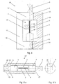
- Fig. 1 shows specimen 1 used in the method for determining limit failure strain ⁇ f .
- Specimen 1 has an axis of symmetry A and comprises a cylindrical measured part 2 and opposite ends 3.
- the specimen is provided with a linear marker 4 parallel to the axis of symmetry A of the specimen 1.
- the linear marker 4 may be a scratch or other suitable linear mark that will remain clearly visible after specimen 1 has been heated/cooled and fractured as a result of twisting and which does not affect twisting of specimen 1.
- Each of the opposite ends 3 of specimen 1, which are substantially identical, comprises an inside cylindrical section 5 which has a larger diameter than the measured part 2 and is adjacent to the measured part 2 and comprises an outside section 6 which has a square diameter, is adjacent to the cylindrical section 5 and the cross-section of which has a shorter diagonal than the diameter of the inside cylindrical section 5.
- the specimen 1 prepared in such a way is brought to a predetermined test temperature by heating or cooling, i.e. to a temperature for which coefficient a is to be determined and consequently - limit failure strain ⁇ f .
- the specimen 1 can be heated to a predetermined test temperature by means of an induction coil 16 surrounding the measured part 2 of the specimen 1 or in a furnace.
- the specimen 1 is brought to a predetermined temperature in a cooling device.
- the specimen 1 is subjected to torsion strain until fracture of the specimen 1 by applying torque to one of the end part 3 in the plane perpendicular to the axis of symmetry of the specimen, with the opposite end part 3 of the specimen 1 being immovably retained.
- said torque is applied by a pair of forces.
- an instrument 10, 10' ( Fig. 3, 4a, 4b ) is used in which one end part 3 of the specimen 1 is retained in an immovable manner and the opposite end part 3 of the specimen 1 is mounted rotatably so that torque can be applied thereto.
- the instrument 10, 10' with the specimen 1 is fixed using external retaining means, such as a vice (not show in the drawing).
- measurement is carried out, using, for example, a microscope, of the angle of twist ⁇ of the measured part 2 of the specimen 1 which corresponds to the fracture plane of the specimen 1 relative to displacement of the specimen's marker 4 in that plane with respect to the initial state before torsional strain.
- the angle of twist ⁇ of the measured part 2 of the specimen 1 corresponding to the facture plane of the specimen 1 is schematically shown in Fig. 2 .
- the value of shear strain angle ⁇ 12 is determined, according to known methods, which is used to determine the value of coefficient a in equations (7) and (6).
- the instrument 10 is in the frame-like shape holding the specimen 1 in a non-tilted position and it comprises two opposite bases 11, 12 connected with side arms 13.
- a through-hole 14 is made which has a square cross-section.
- the side length of said square through-hole 14 ensures that the outside section 6 of the specimen's end part 3, which has a square cross-section, can be easily placed therein, without the possibility of rotation, and prevents the inside cylindrical section 5 of the specimen's end part 3 from entering the square through-hole 14.
- a through-hole 15 is shaped which has a round cross-section and a diameter which allows the outside section 6 with square cross-section of the specimen's end part 3 to easily go through it and the cylindrical inside section 5 of the specimen's end part 3 to be placed therein with the possibility of rotation; wherein the outside section 6 having square cross section of the specimen's end part 3 protrudes at least partially outside the round through-hole 15 of the instrument's base 12.
- the assembly may comprise at least one induction coil 16 which surrounds the measured part 2 of the specimen 1.
- Test temperature is determined by means of known methods, preferably using at least one thermocouple (not show in the drawing) which is in contact with the measured part 2 of the specimen 1.
- the instrument 10 is configured for being immovably held by means of external retaining means, for example, by a vice, and ensures stable support for the specimen 1 while the method for determining values of limit failure strain ⁇ f is carried out.
- the use of at least one induction coil 16 for heating the specimen 1 makes it possible to heat the specimen 1 in the tool 10 without the necessity of placing it in a furnace.
- the specimen 1 is twisted by means of a tool, e.g. wrench, which is placed on the protruding outside section 6, with square cross-section, of the end part 3 of the specimen 1, until fracture of the measured part 2.
- the instrument 10' is in the shape of a cylinder that holds the specimen 1 inside in a non-tilted position relative to the axis and comprises one base 11 with a through-hole 14 with a square cross-section and an opposite open end 17.
- the side length of the square through-hole 14 of the base 11 of the instrument 10' ensures that the outside section 6 the specimen's (1) end part (3) which has a square cross-section, can be easily place therein, in an non-rotatable manner and prevents the cylindrical inside section 5 of the specimen's 1 end part 3 from entering the square through-hole 14.
- the inside diameter of the instrument 10' is selected to ensure that cylindrical section 5 of the specimen's 1 end part 3 can rotate therein, whereas the length of the inside cylindrical surface of the instrument 10', from the base 11 to the open end 17 is selected such that the outside section , which has a square cross-section, of the specimen's end part 3 projects at least partially beyond the open end 17 of the instrument 10'.
- the outside cylindrical surface of the instrument 10' has flattened portions 18 on the opposite sides relative to its diameter, for mounting the instrument 10' in the external retaining means, for example, in a vice.
- the specimen 1 is twisted by means of a tool, e.g. wrench, placed on the protruding outside section 6 of the end part 3 of the specimen 1.
- the assembly of the instrument 10' and the specimen 1 according to the second embodiment of the invention is used for heating the specimen 1 in a furnace or cooling it in a cooling device.
- the specimen 1 is placed in the instrument 10' and the entire assembly is heated or cooled to a predetermined temperature.
- the instrument 10' with the specimen 1 is retained, e.g. in a vice, and the specimen is twisted, e.g. by means of a wrench, placed on the protruding outside section 6 of the end part 3 of the specimen, which has a square cross-section, until fracture of the measured part 2 of the specimen 1.
- Specimen 1 such as the specimen described in relation to Fig. 2 , was tested in room temperature (20°C); the specimen was placed in an instrument 10, such as the instrument described in relation to Fig. 3 .
- Displacement of the linear marker 4 located on the surface of the measured part 2 of the specimen 1 showed that the fracture of the specimen 1 occurred after almost two turns made in the fracture plane.
- the angle of twist ⁇ in the fracture plane of the specimen 1 was measured by the measuring microscope and its radian measure, corresponding to the value of angle of shear, was 8.792 rad (506,36°) (according to Fig. 2 ).
- limit failure strain ⁇ f may be calculated for other stress states and given temperature, which in this case was the room (20°C) temperature.
- the material destruction criterion defined in the above way may be implemented and successfully applied for strength calculations in contemporary engineering structures carried out with the use of computer software using e.g. the Finite Element Method (FEM), in particular in automotive and aviation industry.
- FEM Finite Element Method
Landscapes
- Physics & Mathematics (AREA)
- General Physics & Mathematics (AREA)
- General Health & Medical Sciences (AREA)
- Chemical & Material Sciences (AREA)
- Analytical Chemistry (AREA)
- Biochemistry (AREA)
- Life Sciences & Earth Sciences (AREA)
- Health & Medical Sciences (AREA)
- Immunology (AREA)
- Pathology (AREA)
- Engineering & Computer Science (AREA)
- Aviation & Aerospace Engineering (AREA)
- Investigating Strength Of Materials By Application Of Mechanical Stress (AREA)
Abstract
Description
- The invention relates to a method and assembly for determining deformation causing failure of a ductile structural material subjected to various stress states and temperatures.
- A criterion of material failure is commonly used in strength calculations, which are performed, for example, by the Finite Element Method (FEM), for contemporary engineering structures (planes, cars and others). At present, all structural calculations are performed by means of computer software packages in which several criteria of material failure are typically implemented. It is usually a problem to determine coefficients related to such criteria (calibration) for given material and temperature.
- Determining a criterion of failure is particularly difficult in the case of elastic-plastic (ductile) materials that do not follow Hook's law. One of the criteria used for such materials is strain criterion.
- Thus, the ability of elastic-plastic materials, such as metal alloys, to reach permanent deformation is a very important property considering the process of forming and application of constructional elements. This ability is dependent on the state of stress in which a material is subjected to permanent deformation.
- The prior art discloses criteria for determining the failure moment in elastic-plastic materials, which can be divided into stress and strain criteria. Due to changes in the state of stress caused by the localization of deformation, strain criteria are more widely used.
- According to a generally accepted theory, the ability of given material to reach states of permanent deformation, measured by the value of limit failure strain εf , corresponding to failure of the material, is determined by the so called triaxial stress coefficient η. This coefficient is defined as follows:


- Dependence between limit failure strain εf in the general case of strain state, calculated as equivalent strain which is an invariant of strain tensor:

- One proposal of an equation that provides a good description of experimental data was published in the following work: Hancock J. W. and Mackenzie A. C., "On the mechanism of ductile failure in high-strength steels subjected to multi-axial stress states", J. Mech. Phys. Sol., (1976), 147-175 , namely:

- Determination of coefficient a, which is included in the above equation (5), makes it possible to univocally determine limit failure strain εf of ductile materials for all stress states.
- Coefficient a in the equation (5) is a coefficient which is dependent on temperature and which fully characterizes the ability of a material to reach limit strains causing material failure in all stresses states at given temperature.
- As results from equation (5), in order to determine the value of coefficient a it is necessary to cause destruction of a material at a specific constant stress state (at constant value of coefficient η).
- The prior art discloses methods for determining coefficient a for elastic-plastic materials which are based, among others, on a static tensile test carried out in a metal specimen until failure. It should be noted, however, that this approach does not fulfill the requirement for maintaining a constant stress state (constant coefficient η) during the entire process, until failure. It is due to localization of deformation in the form of a narrowing in the measured part of a specimen, which leads to triaxial tensile stress. Results obtained in this way do not fully reflect the real properties of the tested material and the method of obtaining them is even at variance with the present state of the art. Nevertheless, the results of such tests are commonly used because in order to obtain accurate results it is necessary to construct full-scale mathematical models or solve complicated sets of equations, which is very laborious and entails considerable costs and high level of complexity.
- Moreover, the methods known in the prior art require the use of specialized testing machines enabling one to carry out experiments in strictly controlled conditions (e.g. due to complicated grip systems).
- In the case of a torsion test, the frequently used prior-art specimens are thin-walled axisymmetric specimens for which almost constant axial stress distribution in radial direction of the specimen may be assumed, which is required to determine selected material properties (for example, yield stress). However, the cost of producing such a hollow specimen is higher than e.g. the cost of producing a solid specimen and it involves a greater amount of labour.
- One know and hitherto used method for determining limit failure strain of ductile structural materials has been described, for example, in the following work: Wierzbicki T., Bao Y., Lee Y. W., Bai Y., "Calibration and evaluation of seven fracture models", International Journal of Mechanical Sciences, 47 (2005), pp.719-743.
- The purpose of the invention is to develop a method for determining deformation causing failure εf of a ductile structural material in various stress states and temperatures, which will reflect real properties of a material, which will be simple and will be characterized by a low cost of production and calibration.
- Another purpose of the invention is to develop a method which will enable determining the value of εf for both positive and negative temperature.
- The purpose of the invention is also to develop an assembly for carrying out the above indicated method.
- The present invention is based on the thesis that pure shear along the surface of a cylindrical specimen being twisted is the easiest state of stress which can be obtained and maintained from the beginning to the end of a deformation process. For this kind of load state σm = 0, η = 0, and

- Thus, based on equation (6), after determining coefficient a, which characterizes given material in given temperature, it is possible to determine limit failure strain εf for individual stress triaxiality coefficients η, which represent individual states of stress in given temperature.
- For the state of pure torsion, equation (4) has the following form:

- Therefore, if the value of angle of shear γ 12 is known, it is possible to determine coefficient a and use it in order to determine limit failure strain εf for individual stress triaxiality coefficients η, which represent individual stress states at given temperature, according to equation (6).
- According to the invention, the method for determining deformation causing failure of a ductile structural material subjected to various stress states and temperatures, using an assembly of an instrument and a specimen, in which a specimen of given material is twisted in a predetermined temperature, comprising the following steps:
- producing a specimen of a material to be tested; the specimen having an axis of symmetry and comprising a measured part and opposite end parts and providing with a linear marker parallel to the specimen's axis of symmetry on a surface of the measured part,
- placing the specimen in the instrument with one end part of the specimen secured immovable relative to the instrument and the other, opposite end part of the specimen, mounted in a rotatable manner with the possibility of applying torque that induces twisting of the measured portion of the specimen, and fixing the instrument with the specimen with external retaining means,
- bringing the specimen to a predetermined test temperature;
- inducing a state of pure shear in the specimen by twisting it, when the predetermined temperature has been obtained and until fracture,
- measuring the angle of twist ϕ of the specimen's measured portion corresponding to the specimen's fracture plane, in relation to displacement of the specimen's linear marker in the fracture plane and referring to the initial state before torsional strain,
- determining the value of angle of shear γ12 based on the angle of twist ϕ of the specimen's measured portion,
- determining the value of coefficient a based on the value of angle of shear γ12, according to the equation:

- determining the value of limit failure strain εf , corresponding to failure of the tested material in various stress states and at given temperature at which the specimen was subjected to twisting strain based on the equation:

- where η is stress triaxiality coefficient.
- Preferably, the twisting is performed by applying torque to one end part of the specimen in the plane perpendicular to the axis of symmetry of the specimen, with the other end part of the specimen being immovably held .
- The specimen is brought to a predetermined test temperature by heating it by means of at least one induction coil surrounding the measured portion of the specimen placed in the instrument or by placing the instrument with the specimen in a furnace.
- In an alternative embodiment the specimen is brought to a predetermined test temperature by cooling the specimen secured in an instrument in a cooling device.
- According to the invention, an assembly of an instrument and a specimen for determining deformation causing failure of a ductile structural material at various stress states and temperatures, wherein the specimen has an axis of symmetry and comprises a measured part and opposite end parts and a linear marker parallel to the specimen's axis of symmetry on the surface of the measured part, the instrument has at least one fastening part fitted to at least one end part of the specimen, is characterized in that each of the opposite ends of the specimen comprises a cylindrical inside section having a larger diameter than the measured part and being adjacent to the measured part, and comprises an outside section which has a square cross-section, which is adjacent to the cylindrical inside section and has a shorter diagonal than the diameter of the cylindrical inside section, the instrument has a shape configured to retain the specimen in an untilting position and comprises at least one base in which a through-hole is made which has a square cross-section and a side length which ensures that the outside section of the specimen's end part having a square cross-section can be easily placed therein, without the possibility of being rotated, and which prevents the cylindrical inside section of the specimen's end part from entering the through-hole.
- Preferably, the instrument is in the a frame-like shape of and comprises two opposite bases connected with side arms, wherein, in the base opposite to the base with a square through-hole, there is shaped a round through-hole having a diameter which ensures that the outside section of the specimen's end part having a square cross-section can freely/easily go through the whole and the cylindrical inside section of the specimen's end can be placed therein, with the possibility of rotation, wherein the outside section of the specimen's end having a square cross-section protrudes at least partially outside the round hole of the base.
- The measured part of the specimen is surrounded by at least one induction coil for heating the specimen.
- The instrument is adjusted for being immovably fixed by means of external retaining means.
- In another variant of the invention the instrument is in the shape of a cylinder and comprises one base with a through-hole having a square cross-section and an opposite open end, wherein the inside diameter of the instrument is selected to ensure rotation of the cylindrical section of the specimen's end part, without the possibility of tilting the specimen, and the length of the inside surface of the instrument, from the base to the open end, is selected such that the outside section of the specimen's end part having square cross-section protrudes at least partially outside the open end of the instrument.
- In this variant, the outside surface of the instrument may have flat areas on the opposite sides of its diameter for mounting in the external retaining means.
- The method according to the present invention, as compared to the methods known from the prior art, does not require the use of any expensive specialized testing machines, which often have large dimensions and require specialized machine operators. The instrument according to the invention is characterized by small compact and simple structure and it can be intuitively and easily used, which makes it possible to reduce the risk of human error in the course of a test.
- The method according to the present invention is also characterized by low costs of calibrating the failure criterion and make it possible to determine this criterion for both positive and negative temperatures.
- Moreover, considering the test characteristics, the exact value of applied torque is not essential; it only has to be high enough to cause fracture of the specimen. Therefore, it is not necessary to use specialized means for monitoring the value of applied torque, which facilities and simplifies the entire procedure.
- Moreover, due to the fact that the method of present invention uses pure twisting, which is assisted by a specific shape of the instrument, constant stress state is maintained in a specimen throughout the duration of the test, which makes it possible to determine the value of coefficient a which is not contrary to the present state of the art an which reflects in the most accurate way the real value for given material in given temperature.
- According to the method of the present invention, it is not necessary to maintain approximately constant stress distribution in the radial direction of the specimen. Thus, it is not necessary to use thin-walled specimens and solid specimens may be used which are basically cheaper and their production is easier.
- The subject matter of the invention is presented in the embodiments in the drawings, wherein:
- Fig. 1
- shows a side view of a specimen used in the instruments according to the invention,
- Fig. 2
- shows schematically a method for determining torsion angle ϕ in the measured part of a specimen which angle corresponds to the specimen's fracture plane.
- Fig. 3
- shows an embodiment of the assembly for determining deformation causing failure of a ductile structural material in various stress states and temperatures, comprising the instrument and specimen of
fig. 1 , a side view and partial cross-section thereof, - Fig. 4a, 4b
- show another embodiment of the assembly according to the invention comprising the instrument and specimen of
Fig. 1 , a side view and partial cross-section, and a view from one end, - Fig. 5
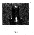
- show a view of the measured part of the specimen after torsional fracture indicating displacement of the linear marker.
- As discussed above, in order to determine deformation causing failure of ductile structural material subjected to various stress states, it is necessary to determine the value of coefficient a included in equation (5).
- For this purpose, according to the invention, in a specimen made of a tested material and brought to required temperature, the state of pure shear is induced by twisting the specimen until fracture, with one end part of the specimen being retained and the other end part being affected by torque. Next, the angle of twist ϕ corresponding to the fracture plane of the measured part is determined, and on the basis thereof the angle of shear γ 12 is determined by known methods and subsequently coefficient a for given material and temperature is determined on the basis of equation (6).
- Determination of coefficient a makes it possible to determine the limit failure strain εf of a ductile material at given temperature for various stress states which are characterized by coefficient η according to equation (1).
-
Fig. 1 showsspecimen 1 used in the method for determining limit failure strain εf .Specimen 1 has an axis of symmetry A and comprises a cylindrical measuredpart 2 and opposite ends 3. On the surface of the measuredpart 2, the specimen is provided with alinear marker 4 parallel to the axis of symmetry A of thespecimen 1. Thelinear marker 4 may be a scratch or other suitable linear mark that will remain clearly visible afterspecimen 1 has been heated/cooled and fractured as a result of twisting and which does not affect twisting ofspecimen 1. - Each of the opposite ends 3 of
specimen 1, which are substantially identical, comprises an insidecylindrical section 5 which has a larger diameter than the measuredpart 2 and is adjacent to the measuredpart 2 and comprises anoutside section 6 which has a square diameter, is adjacent to thecylindrical section 5 and the cross-section of which has a shorter diagonal than the diameter of the insidecylindrical section 5. - The
specimen 1 prepared in such a way is brought to a predetermined test temperature by heating or cooling, i.e. to a temperature for which coefficient a is to be determined and consequently - limit failure strain εf . - The
specimen 1 can be heated to a predetermined test temperature by means of aninduction coil 16 surrounding the measuredpart 2 of thespecimen 1 or in a furnace. - In the case of determining limit failure strain εf for a lower temperature than the ambient temperature, the
specimen 1 is brought to a predetermined temperature in a cooling device. - When a predetermined temperature has been achieved, the
specimen 1 is subjected to torsion strain until fracture of thespecimen 1 by applying torque to one of theend part 3 in the plane perpendicular to the axis of symmetry of the specimen, with theopposite end part 3 of thespecimen 1 being immovably retained. Preferably, said torque is applied by a pair of forces. - In order to fix one end of the
specimen 1 and subject the specimen to twisting, preferably aninstrument 10, 10' (Fig. 3, 4a, 4b ) is used in which oneend part 3 of thespecimen 1 is retained in an immovable manner and theopposite end part 3 of thespecimen 1 is mounted rotatably so that torque can be applied thereto. Prior to applying torque, theinstrument 10, 10' with thespecimen 1 is fixed using external retaining means, such as a vice (not show in the drawing). - After fracture of the measured
part 2 of thespecimen 1, measurement is carried out, using, for example, a microscope, of the angle of twist ϕ of the measuredpart 2 of thespecimen 1 which corresponds to the fracture plane of thespecimen 1 relative to displacement of the specimen'smarker 4 in that plane with respect to the initial state before torsional strain. The angle of twist ϕ of the measuredpart 2 of thespecimen 1 corresponding to the facture plane of thespecimen 1 is schematically shown inFig. 2 . - Based on the angle of twist ϕ of the measured
part 2 of thespecimen 1, the value of shear strain angle γ 12, is determined, according to known methods, which is used to determine the value of coefficient a in equations (7) and (6). - Determination of coefficient a makes it possible to determine, on the basis of equation (5), the values of limits failure strain εf causing failure of the tested material in various stress states and temperatures.
- In order to carry out the above described method for determining the values of equivalent limits failure strain εf , according to the invention, there is provided an assembly of the
instrument 10, 10' and thespecimen 1, as shown in the embodiments inFigures 3, 4a, 4b . Thespecimen 1 is described below. - In the first embodiment in
Fig. 3 , theinstrument 10 is in the frame-like shape holding thespecimen 1 in a non-tilted position and it comprises twoopposite bases side arms 13. In onebase 11, a through-hole 14 is made which has a square cross-section. The side length of said square through-hole 14 ensures that theoutside section 6 of the specimen'send part 3, which has a square cross-section, can be easily placed therein, without the possibility of rotation, and prevents the insidecylindrical section 5 of the specimen'send part 3 from entering the square through-hole 14. - In the
base 12, which is opposite to the base 11 with the square through-hole 14, a through-hole 15 is shaped which has a round cross-section and a diameter which allows theoutside section 6 with square cross-section of the specimen'send part 3 to easily go through it and the cylindrical insidesection 5 of the specimen'send part 3 to be placed therein with the possibility of rotation; wherein theoutside section 6 having square cross section of the specimen'send part 3 protrudes at least partially outside the round through-hole 15 of the instrument'sbase 12. - In order to heat the
specimen 1, the assembly may comprise at least oneinduction coil 16 which surrounds the measuredpart 2 of thespecimen 1. Test temperature is determined by means of known methods, preferably using at least one thermocouple (not show in the drawing) which is in contact with the measuredpart 2 of thespecimen 1. The use of suitable wiring of at least oneinduction coil 16 and connection it with at least one thermocouple, preferably with feedback, makes it possible to obtain a uniform temperature along the entire length of the measured part of the specimen. - The
instrument 10 is configured for being immovably held by means of external retaining means, for example, by a vice, and ensures stable support for thespecimen 1 while the method for determining values of limit failure strain εf is carried out. The use of at least oneinduction coil 16 for heating thespecimen 1 makes it possible to heat thespecimen 1 in thetool 10 without the necessity of placing it in a furnace. When thespecimen 1 has been heated and theinstrument 10 with thespecimen 1 has been placed in a vice, thespecimen 1 is twisted by means of a tool, e.g. wrench, which is placed on the protruding outsidesection 6, with square cross-section, of theend part 3 of thespecimen 1, until fracture of the measuredpart 2. - In the second embodiment of the assembly, show in
Figures 4a, 4b , wherein identical elements are marked with the same reference numbers as those in the first embodiment, the instrument 10' is in the shape of a cylinder that holds thespecimen 1 inside in a non-tilted position relative to the axis and comprises onebase 11 with a through-hole 14 with a square cross-section and an oppositeopen end 17. - Like in the first embodiment, the side length of the square through-
hole 14 of thebase 11 of the instrument 10' ensures that theoutside section 6 the specimen's (1) end part (3) which has a square cross-section, can be easily place therein, in an non-rotatable manner and prevents the cylindrical insidesection 5 of the specimen's 1end part 3 from entering the square through-hole 14. - The inside diameter of the instrument 10' is selected to ensure that
cylindrical section 5 of the specimen's 1end part 3 can rotate therein, whereas the length of the inside cylindrical surface of the instrument 10', from the base 11 to theopen end 17 is selected such that the outside section , which has a square cross-section, of the specimen'send part 3 projects at least partially beyond theopen end 17 of the instrument 10'. - The outside cylindrical surface of the instrument 10' has flattened
portions 18 on the opposite sides relative to its diameter, for mounting the instrument 10' in the external retaining means, for example, in a vice. When the instrument 10' with thespecimen 1 has been placed in the vice, thespecimen 1 is twisted by means of a tool, e.g. wrench, placed on the protruding outsidesection 6 of theend part 3 of thespecimen 1. - The assembly of the instrument 10' and the
specimen 1 according to the second embodiment of the invention is used for heating thespecimen 1 in a furnace or cooling it in a cooling device. Thespecimen 1 is placed in the instrument 10' and the entire assembly is heated or cooled to a predetermined temperature. When the predetermined temperature has been achieved, the instrument 10' with thespecimen 1 is retained, e.g. in a vice, and the specimen is twisted, e.g. by means of a wrench, placed on the protruding outsidesection 6 of theend part 3 of the specimen, which has a square cross-section, until fracture of the measuredpart 2 of thespecimen 1. - The shape of the instrument 10' ensures that the measured
part 2 of thespecimen 1 is provided with better thermal insulation against the ambient environment than the remaining parts of thespecimen 1, and thus the measuredpart 2 of thespecimen 1 maintains the temperature acquired in a furnace or a cooling device for a longer time. -
Specimen 1, such as the specimen described in relation toFig. 2 , was tested in room temperature (20°C); the specimen was placed in aninstrument 10, such as the instrument described in relation toFig. 3 . - Prior to being deformed, the measured
part 1 was measured up by means of a measuring microscope. The initial radius of the measuredpart 2 of thespecimen 1 was ro = 3,1986 mm and it was assumed that it was not subject to any change under pure shear. -
Instrument 10 with thespecimen 1 was secured in a vice and torque was applied to the protruding outsidesection 6 of theend part 3 of the specimen, and thus the measuredpart 2 of thespecimen 1 was brought to fracture in the plane located at a distance lo= 26,0392 mm from the plane of the end of the fixing area of theopposite end part 3 of thespecimen 1. The specimen in the state after fracture is shown inFig. 5 . - Displacement of the
linear marker 4 located on the surface of the measuredpart 2 of thespecimen 1 showed that the fracture of thespecimen 1 occurred after almost two turns made in the fracture plane. - The angle of twist ϕ in the fracture plane of the
specimen 1 was measured by the measuring microscope and its radian measure, corresponding to the value of angle of shear, was 8.792 rad (506,36°) (according toFig. 2 ). - Based on the known equation:


- This value, in accordance with equation (6) according to the invention, corresponds to the constant value a in the equation (5) describing the dependence between the limit failure strain εf and the stress triaxiality coefficient η for given test temperature.
- Based on the determined constant value a, values of the limit failure strain εf for various stress states were determined:
- For uniaxial tensile test, wherein η=1/3

- For uniaxial compression test, wherein η= -1/3

- Analogically, the value of limit failure strain εf may be calculated for other stress states and given temperature, which in this case was the room (20°C) temperature.
- Therefore, the material destruction criterion defined in the above way may be implemented and successfully applied for strength calculations in contemporary engineering structures carried out with the use of computer software using e.g. the Finite Element Method (FEM), in particular in automotive and aviation industry.
Claims (11)
- A method for determining deformation causing failure of a ductile structural material subjected to various stress states and temperatures, using an assembly of an instrument and a specimen, in which a specimen of given material is subjected to twisting in a predetermined temperature, and further comprising the following steps:producing a specimen of a material to be tested; the specimen having an axis of symmetry and comprising a measured part and opposite end parts and providing with a linear marker parallel to the specimen's axis of symmetry on a surface of the measured part;placing the specimen in the instrument with one end part of the specimen secured immovable relative to the instrument and the other, opposite end part of the specimen, mounted in a rotatable manner with the possibility of applying torque that induces twisting of the measured portion of the specimen, and fixing the instrument with the specimen with external retaining means;bringing the specimen to a predetermined test temperature;inducing in the specimen a state of pure shear by twisting it, when the predetermined temperature has been obtained and until fracture;measuring the angle of twist ϕ of the specimen's measured portion corresponding to the specimen's fracture plane, in relation to displacement of the specimen's linear marker in the fracture plane and referring to the initial state before torsional deformation,determining the value of angle of shear γ12 based on the angle of twist ϕ of the specimen's measured portion,determining the value of coefficient a based on the value of angle of shear γ12, according to the equation:
 determining the value of limit failure strain εf , corresponding to failure of the tested material in various stress states and at given temperature at which the specimen was subjected to twisting strain based on the equation:
 where η is stress triaxiality coefficient.
 - The method according to claim 1, characterized in that the twisting is performed by applying torque to one end part of the specimen in the plane perpendicular to the axis of symmetry of the specimen, with the other end part of the specimen being immovably held .
- The method according to claim 1 or 2, characterized in that the specimen is brought to a predetermined test temperature by heating it by means of at least one induction coil surrounding the measured portion of the specimen placed in the instrument
- The method according to claim 1 or 2, characterized in that the specimen is brought to a predetermined test temperature by heating the specimen placed in the instrument in a furnace.
- The method according to claim 1 or 2, characterized in that the specimen is brought to a predetermined test temperature by cooling the specimen secured in an instrument in a cooling device.
- An assembly of an instrument and a specimen for determining deformation causing failure of a ductile structural material at various stress states and temperatures, using the method of any of claims 1-5; wherein the specimen (1) has an axis of symmetry (A) and comprises a measured part (2) with a linear marker (4) parallel to the specimen's axis of symmetry (A) on its surface and opposite end parts (3); the instrument (10, 10') has at least one fastening part fitted to at least one end part (3) of the specimen (3) characterized in thateach of the opposite end parts (3) of the specimen (1) comprises a cylindrical inside section (5) having a larger diameter than the measured part (2) and being adjacent to the measured part (2), and comprises an outside section (6) which has a square cross-section, which is adjacent to the cylindrical inside section (5) and has a shorter diagonal than the diameter of the cylindrical inside section (5),the instrument (10,10') has a shape configured to retain the specimen (1) in an untilting position and comprises at least one base (11) in which a through-hole (14) is made which has a square cross-section and a side length which ensures that the outside section (6), having a square cross-section, of the specimen's end part (3) can be easily placed therein, without the possibility of being rotated, and which prevents the cylindrical inside section (5) of the specimen's end part (3) from entering the through-hole (14).
- The assembly of an instrument and a specimen according to claim 6, characterized in that the instrument (10) is in the a frame-like shape and comprises two opposite bases (11,12) connected with side arms (13), wherein in the base (12) opposite to the base (11) with a square through-hole (14), there is shaped a round through-hole (15) having a diameter which ensures that the outside section (6) of the specimen's end part (3) having a square cross-section can freely go through the hole and the cylindrical inside section (5) of the specimen's end art (3) can be placed therein, with the possibility of rotation, wherein the outside section (6) of the specimen's end part (3) having a square cross-section protrudes at least partially outside the round hole (15) of the base (12).
- The assembly of an instrument and a specimen according to claim 6, characterized in that the measured part (2) of the specimen (1) is surrounded by at least one induction coil (16) for heating the specimen.
- The assembly of an instrument and a specimen according to claim 7 or 8, characterized in that the instrument (10) is configured to be immovably fixed by means of external retaining means.
- The assembly of an instrument and a specimen according to claim 6, characterized in that the instrument (10') is in the shape of a cylinder and comprises one base (11) with a through-hole (14) having a square cross-section and an opposite open end (17), wherein the inside diameter of the instrument (10') is selected to ensure rotation of the cylindrical section (5) of the specimen's end part (3), without the possibility of tilting the specimen, (1) and the length of the inside surface of the instrument (10'), from the base (11) to the open end (17), is selected such that the outside section (6) of the specimen's end part (3) having square cross-section protrudes at least partially outside the open end (17) of the instrument.
- The assembly of an instrument and a specimen according to claim 6 or 10, characterized in that the outside surface of the instrument (10') has flat areas (18) on the opposite sides of its diameter for mounting in the external retaining means.
Applications Claiming Priority (1)
| Application Number | Priority Date | Filing Date | Title |
|---|---|---|---|
| PL428304A PL428304A1 (en) | 2018-12-21 | 2018-12-21 | Method and set for determining deformation corresponding to destruction of a ductile construction material in various stress states and at a given temperature |
Publications (2)
| Publication Number | Publication Date |
|---|---|
| EP3671169A1 true EP3671169A1 (en) | 2020-06-24 |
| EP3671169B1 EP3671169B1 (en) | 2022-10-19 |
Family
ID=69411098
Family Applications (1)
| Application Number | Title | Priority Date | Filing Date |
|---|---|---|---|
| EP19218541.1A Active EP3671169B1 (en) | 2018-12-21 | 2019-12-20 | Method for determining deformation causing failure of ductile structural material subjected to various stress states and temperatures |
Country Status (4)
| Country | Link |
|---|---|
| EP (1) | EP3671169B1 (en) |
| DK (1) | DK3671169T3 (en) |
| FI (1) | FI3671169T3 (en) |
| PL (2) | PL428304A1 (en) |
Cited By (1)
| Publication number | Priority date | Publication date | Assignee | Title |
|---|---|---|---|---|
| CN120145635A (en) * | 2025-02-10 | 2025-06-13 | 中国科学院力学研究所 | A method for determining the performance index of lightweight alloy materials for deep-sea large cylindrical shell structures |
Citations (4)
| Publication number | Priority date | Publication date | Assignee | Title |
|---|---|---|---|---|
| JP2000234991A (en) * | 1999-02-15 | 2000-08-29 | Sanyo Special Steel Co Ltd | Measuring method of deformation resistance |
| KR20040059949A (en) * | 2002-12-30 | 2004-07-06 | 주식회사 포스코 | Hot Torsion Deformation Tester and Testing Method Thereof |
| US20110005331A1 (en) * | 2009-07-07 | 2011-01-13 | Jy-An Wang | Apparatuses for Prestressing Rod-Type Specimens in Torsion for In-Situ Passive Fracture Toughness Testing in an Extremely High-Pressure Environment of Hydrogen |
| CN105372125B (en) * | 2015-12-23 | 2018-02-23 | 济南科汇试验设备有限公司 | A kind of torsion testing machine clamp fixture and its application method |
-
2018
- 2018-12-21 PL PL428304A patent/PL428304A1/en unknown
-
2019
- 2019-12-20 FI FIEP19218541.1T patent/FI3671169T3/en active
- 2019-12-20 PL PL19218541.1T patent/PL3671169T3/en unknown
- 2019-12-20 EP EP19218541.1A patent/EP3671169B1/en active Active
- 2019-12-20 DK DK19218541.1T patent/DK3671169T3/en active
Patent Citations (4)
| Publication number | Priority date | Publication date | Assignee | Title |
|---|---|---|---|---|
| JP2000234991A (en) * | 1999-02-15 | 2000-08-29 | Sanyo Special Steel Co Ltd | Measuring method of deformation resistance |
| KR20040059949A (en) * | 2002-12-30 | 2004-07-06 | 주식회사 포스코 | Hot Torsion Deformation Tester and Testing Method Thereof |
| US20110005331A1 (en) * | 2009-07-07 | 2011-01-13 | Jy-An Wang | Apparatuses for Prestressing Rod-Type Specimens in Torsion for In-Situ Passive Fracture Toughness Testing in an Extremely High-Pressure Environment of Hydrogen |
| CN105372125B (en) * | 2015-12-23 | 2018-02-23 | 济南科汇试验设备有限公司 | A kind of torsion testing machine clamp fixture and its application method |
Non-Patent Citations (3)
| Title |
|---|
| FALESKOG JONAS ET AL: "Tension-torsion fracture experiments-Part I: Experiments and a procedure to evaluate the equivalent plasti", INTERNATIONAL JOURNAL OF SOLIDS AND STRUCTURES, NEW YORK, NY, US, vol. 50, no. 25, 4 September 2013 (2013-09-04), pages 4241 - 4257, XP028735940, ISSN: 0020-7683, DOI: 10.1016/J.IJSOLSTR.2013.08.029 * |
| HANCOCK J W ET AL: "On the mechanisms of ductile failure in high-strength steels subjected to multi-axial stress-states", JOURNAL OF THE MECHANICS AND PHYSICS OF SOLIDS, PERGAMON PRESS, OXFORD, GB, vol. 24, no. 2-3, 1 June 1976 (1976-06-01), pages 147 - 160, XP024458857, ISSN: 0022-5096, [retrieved on 19760601], DOI: 10.1016/0022-5096(76)90024-7 * |
| WIERZBICKI T.BAO Y.LEE Y. W.BAI Y.: "Calibration and evaluation of seven fracture models", INTERNATIONAL JOURNAL OF MECHANICAL SCIENCES, vol. 47, 2005, pages 719 - 743, XP004944060, DOI: 10.1016/j.ijmecsci.2005.03.003 |
Cited By (1)
| Publication number | Priority date | Publication date | Assignee | Title |
|---|---|---|---|---|
| CN120145635A (en) * | 2025-02-10 | 2025-06-13 | 中国科学院力学研究所 | A method for determining the performance index of lightweight alloy materials for deep-sea large cylindrical shell structures |
Also Published As
| Publication number | Publication date |
|---|---|
| FI3671169T3 (en) | 2023-01-13 |
| PL3671169T3 (en) | 2023-02-20 |
| DK3671169T3 (en) | 2022-12-19 |
| PL428304A1 (en) | 2020-06-29 |
| EP3671169B1 (en) | 2022-10-19 |
Similar Documents
| Publication | Publication Date | Title |
|---|---|---|
| Sui et al. | New technique for measuring low-temperature properties of asphalt binders with small amounts of material | |
| Szusta et al. | Experimental study of the low-cycle fatigue life under multiaxial loading of aluminum alloy EN AW-2024-T3 at elevated temperatures | |
| US20090266138A1 (en) | Method and Apparatus for Shear Strain Testing of Strain Sensors | |
| US5199305A (en) | Method and apparatus for measuring the strain developed in a coated surface | |
| US5641912A (en) | Method for remote application of variable load and/or displacement to specimens, components, or systems | |
| US11175206B2 (en) | Tube pure shear loading device and method | |
| Starman et al. | Shear test-based identification of hardening behaviour of stainless steel sheet after onset of necking | |
| EP3671169B1 (en) | Method for determining deformation causing failure of ductile structural material subjected to various stress states and temperatures | |
| CN107505213B (en) | Novel small punch test device and test method thereof | |
| Wiederhorn et al. | Mechanical properties | |
| CN108195672A (en) | A kind of material tension-torsion bursting stress and the Forecasting Methodology in failure mechanics direction | |
| CN117606923A (en) | Anchor stress corrosion test methods, devices and applications in corrosive environments | |
| Lu et al. | Quasi-static torsion characterization of micro-diameter copper wires | |
| KR20090070624A (en) | Residual stress measuring equipment calibration device and method | |
| CN103115603B (en) | A kind of apparatus and method measuring biaxial strain in material pull and torsion test | |
| Antherieu et al. | Principle and experimental validation of a new apparatus allowing large deformation in pure bending: Application to thin wire | |
| Fallen et al. | Measuring the elastic properties of fine wire | |
| Koch | Tests for stress-corrosion cracking | |
| Biesiekierski et al. | Mechanical testing of metallic biomaterials | |
| Liu et al. | Verification of a novel micro-torsion tester based on electromagnetism using an improved torsion pendulum technique | |
| CN112611656A (en) | Accurate measurement method for low-temperature elongation of aluminum alloy for aerospace | |
| Gilat et al. | High-strain-rate characterization of ceramics in shear | |
| Nikolov et al. | Shear modulus determination of S235JRC cold drawn steel by tension and torsion tests | |
| CN112417740A (en) | An accurate measurement method of low temperature fracture elongation of aluminum alloy for aerospace | |
| CN105738224B (en) | Test method for mechanical properties of electron gun thermal sub-assemblies |
Legal Events
| Date | Code | Title | Description |
|---|---|---|---|
| PUAI | Public reference made under article 153(3) epc to a published international application that has entered the european phase |
Free format text: ORIGINAL CODE: 0009012 |
|
| STAA | Information on the status of an ep patent application or granted ep patent |
Free format text: STATUS: THE APPLICATION HAS BEEN PUBLISHED |
|
| AK | Designated contracting states |
Kind code of ref document: A1 Designated state(s): AL AT BE BG CH CY CZ DE DK EE ES FI FR GB GR HR HU IE IS IT LI LT LU LV MC MK MT NL NO PL PT RO RS SE SI SK SM TR |
|
| AX | Request for extension of the european patent |
Extension state: BA ME |
|
| STAA | Information on the status of an ep patent application or granted ep patent |
Free format text: STATUS: REQUEST FOR EXAMINATION WAS MADE |
|
| 17P | Request for examination filed |
Effective date: 20201001 |
|
| RBV | Designated contracting states (corrected) |
Designated state(s): AL AT BE BG CH CY CZ DE DK EE ES FI FR GB GR HR HU IE IS IT LI LT LU LV MC MK MT NL NO PL PT RO RS SE SI SK SM TR |
|
| REG | Reference to a national code |
Ref country code: DE Ref legal event code: R079 Ref document number: 602019020778 Country of ref document: DE Free format text: PREVIOUS MAIN CLASS: G01M0005000000 Ipc: G01N0003280000 |
|
| GRAP | Despatch of communication of intention to grant a patent |
Free format text: ORIGINAL CODE: EPIDOSNIGR1 |
|
| STAA | Information on the status of an ep patent application or granted ep patent |
Free format text: STATUS: GRANT OF PATENT IS INTENDED |
|
| RIC1 | Information provided on ipc code assigned before grant |
Ipc: G01M 5/00 20060101ALI20220627BHEP Ipc: G01N 3/26 20060101ALI20220627BHEP Ipc: G01N 3/28 20060101AFI20220627BHEP |
|
| INTG | Intention to grant announced |
Effective date: 20220719 |
|
| GRAS | Grant fee paid |
Free format text: ORIGINAL CODE: EPIDOSNIGR3 |
|
| GRAA | (expected) grant |
Free format text: ORIGINAL CODE: 0009210 |
|
| STAA | Information on the status of an ep patent application or granted ep patent |
Free format text: STATUS: THE PATENT HAS BEEN GRANTED |
|
| AK | Designated contracting states |
Kind code of ref document: B1 Designated state(s): AL AT BE BG CH CY CZ DE DK EE ES FI FR GB GR HR HU IE IS IT LI LT LU LV MC MK MT NL NO PL PT RO RS SE SI SK SM TR |
|
| REG | Reference to a national code |
Ref country code: GB Ref legal event code: FG4D |
|
| REG | Reference to a national code |
Ref country code: CH Ref legal event code: EP |
|
| REG | Reference to a national code |
Ref country code: IE Ref legal event code: FG4D |
|
| REG | Reference to a national code |
Ref country code: DE Ref legal event code: R096 Ref document number: 602019020778 Country of ref document: DE |
|
| REG | Reference to a national code |
Ref country code: AT Ref legal event code: REF Ref document number: 1525835 Country of ref document: AT Kind code of ref document: T Effective date: 20221115 |
|
| REG | Reference to a national code |
Ref country code: DK Ref legal event code: T3 Effective date: 20221212 |
|
| REG | Reference to a national code |
Ref country code: SE Ref legal event code: TRGR |
|
| REG | Reference to a national code |
Ref country code: NL Ref legal event code: FP |
|
| PGFP | Annual fee paid to national office [announced via postgrant information from national office to epo] |
Ref country code: NL Payment date: 20221110 Year of fee payment: 4 Ref country code: FR Payment date: 20221115 Year of fee payment: 4 Ref country code: FI Payment date: 20221122 Year of fee payment: 4 Ref country code: DK Payment date: 20221220 Year of fee payment: 4 Ref country code: DE Payment date: 20221110 Year of fee payment: 4 |
|
| REG | Reference to a national code |
Ref country code: LT Ref legal event code: MG9D |
|
| PG25 | Lapsed in a contracting state [announced via postgrant information from national office to epo] |
Ref country code: PT Free format text: LAPSE BECAUSE OF FAILURE TO SUBMIT A TRANSLATION OF THE DESCRIPTION OR TO PAY THE FEE WITHIN THE PRESCRIBED TIME-LIMIT Effective date: 20230220 Ref country code: NO Free format text: LAPSE BECAUSE OF FAILURE TO SUBMIT A TRANSLATION OF THE DESCRIPTION OR TO PAY THE FEE WITHIN THE PRESCRIBED TIME-LIMIT Effective date: 20230119 Ref country code: LT Free format text: LAPSE BECAUSE OF FAILURE TO SUBMIT A TRANSLATION OF THE DESCRIPTION OR TO PAY THE FEE WITHIN THE PRESCRIBED TIME-LIMIT Effective date: 20221019 Ref country code: ES Free format text: LAPSE BECAUSE OF FAILURE TO SUBMIT A TRANSLATION OF THE DESCRIPTION OR TO PAY THE FEE WITHIN THE PRESCRIBED TIME-LIMIT Effective date: 20221019 |
|
| PGFP | Annual fee paid to national office [announced via postgrant information from national office to epo] |
Ref country code: CZ Payment date: 20221121 Year of fee payment: 4 Ref country code: CH Payment date: 20230101 Year of fee payment: 4 |
|
| PG25 | Lapsed in a contracting state [announced via postgrant information from national office to epo] |
Ref country code: RS Free format text: LAPSE BECAUSE OF FAILURE TO SUBMIT A TRANSLATION OF THE DESCRIPTION OR TO PAY THE FEE WITHIN THE PRESCRIBED TIME-LIMIT Effective date: 20221019 Ref country code: LV Free format text: LAPSE BECAUSE OF FAILURE TO SUBMIT A TRANSLATION OF THE DESCRIPTION OR TO PAY THE FEE WITHIN THE PRESCRIBED TIME-LIMIT Effective date: 20221019 Ref country code: IS Free format text: LAPSE BECAUSE OF FAILURE TO SUBMIT A TRANSLATION OF THE DESCRIPTION OR TO PAY THE FEE WITHIN THE PRESCRIBED TIME-LIMIT Effective date: 20230219 Ref country code: HR Free format text: LAPSE BECAUSE OF FAILURE TO SUBMIT A TRANSLATION OF THE DESCRIPTION OR TO PAY THE FEE WITHIN THE PRESCRIBED TIME-LIMIT Effective date: 20221019 Ref country code: GR Free format text: LAPSE BECAUSE OF FAILURE TO SUBMIT A TRANSLATION OF THE DESCRIPTION OR TO PAY THE FEE WITHIN THE PRESCRIBED TIME-LIMIT Effective date: 20230120 |
|
| PGFP | Annual fee paid to national office [announced via postgrant information from national office to epo] |
Ref country code: PL Payment date: 20221201 Year of fee payment: 4 |
|
| REG | Reference to a national code |
Ref country code: DE Ref legal event code: R097 Ref document number: 602019020778 Country of ref document: DE |
|
| PG25 | Lapsed in a contracting state [announced via postgrant information from national office to epo] |
Ref country code: SM Free format text: LAPSE BECAUSE OF FAILURE TO SUBMIT A TRANSLATION OF THE DESCRIPTION OR TO PAY THE FEE WITHIN THE PRESCRIBED TIME-LIMIT Effective date: 20221019 Ref country code: RO Free format text: LAPSE BECAUSE OF FAILURE TO SUBMIT A TRANSLATION OF THE DESCRIPTION OR TO PAY THE FEE WITHIN THE PRESCRIBED TIME-LIMIT Effective date: 20221019 Ref country code: IT Free format text: LAPSE BECAUSE OF NON-PAYMENT OF DUE FEES Effective date: 20221220 Ref country code: EE Free format text: LAPSE BECAUSE OF FAILURE TO SUBMIT A TRANSLATION OF THE DESCRIPTION OR TO PAY THE FEE WITHIN THE PRESCRIBED TIME-LIMIT Effective date: 20221019 |
|
| PGFP | Annual fee paid to national office [announced via postgrant information from national office to epo] |
Ref country code: IE Payment date: 20230411 Year of fee payment: 4 |
|
| REG | Reference to a national code |
Ref country code: BE Ref legal event code: MM Effective date: 20221231 |
|
| PLBE | No opposition filed within time limit |
Free format text: ORIGINAL CODE: 0009261 |
|
| STAA | Information on the status of an ep patent application or granted ep patent |
Free format text: STATUS: NO OPPOSITION FILED WITHIN TIME LIMIT |
|
| PG25 | Lapsed in a contracting state [announced via postgrant information from national office to epo] |
Ref country code: SK Free format text: LAPSE BECAUSE OF FAILURE TO SUBMIT A TRANSLATION OF THE DESCRIPTION OR TO PAY THE FEE WITHIN THE PRESCRIBED TIME-LIMIT Effective date: 20221019 Ref country code: LU Free format text: LAPSE BECAUSE OF NON-PAYMENT OF DUE FEES Effective date: 20221220 Ref country code: AL Free format text: LAPSE BECAUSE OF FAILURE TO SUBMIT A TRANSLATION OF THE DESCRIPTION OR TO PAY THE FEE WITHIN THE PRESCRIBED TIME-LIMIT Effective date: 20221019 |
|
| 26N | No opposition filed |
Effective date: 20230720 |
|
| PG25 | Lapsed in a contracting state [announced via postgrant information from national office to epo] |
Ref country code: SI Free format text: LAPSE BECAUSE OF FAILURE TO SUBMIT A TRANSLATION OF THE DESCRIPTION OR TO PAY THE FEE WITHIN THE PRESCRIBED TIME-LIMIT Effective date: 20221019 Ref country code: BE Free format text: LAPSE BECAUSE OF NON-PAYMENT OF DUE FEES Effective date: 20221231 |
|
| REG | Reference to a national code |
Ref country code: AT Ref legal event code: UEP Ref document number: 1525835 Country of ref document: AT Kind code of ref document: T Effective date: 20221019 |
|
| PG25 | Lapsed in a contracting state [announced via postgrant information from national office to epo] |
Ref country code: IT Free format text: LAPSE BECAUSE OF NON-PAYMENT OF DUE FEES Effective date: 20221220 |
|
| PGFP | Annual fee paid to national office [announced via postgrant information from national office to epo] |
Ref country code: IT Payment date: 20221231 Year of fee payment: 4 |
|
| PGRI | Patent reinstated in contracting state [announced from national office to epo] |
Ref country code: IT Effective date: 20221231 |
|
| PG25 | Lapsed in a contracting state [announced via postgrant information from national office to epo] |
Ref country code: HU Free format text: LAPSE BECAUSE OF FAILURE TO SUBMIT A TRANSLATION OF THE DESCRIPTION OR TO PAY THE FEE WITHIN THE PRESCRIBED TIME-LIMIT; INVALID AB INITIO Effective date: 20191220 |
|
| PG25 | Lapsed in a contracting state [announced via postgrant information from national office to epo] |
Ref country code: CY Free format text: LAPSE BECAUSE OF FAILURE TO SUBMIT A TRANSLATION OF THE DESCRIPTION OR TO PAY THE FEE WITHIN THE PRESCRIBED TIME-LIMIT Effective date: 20221019 |
|
| PG25 | Lapsed in a contracting state [announced via postgrant information from national office to epo] |
Ref country code: MK Free format text: LAPSE BECAUSE OF FAILURE TO SUBMIT A TRANSLATION OF THE DESCRIPTION OR TO PAY THE FEE WITHIN THE PRESCRIBED TIME-LIMIT Effective date: 20221019 |
|
| PG25 | Lapsed in a contracting state [announced via postgrant information from national office to epo] |
Ref country code: MC Free format text: LAPSE BECAUSE OF FAILURE TO SUBMIT A TRANSLATION OF THE DESCRIPTION OR TO PAY THE FEE WITHIN THE PRESCRIBED TIME-LIMIT Effective date: 20221019 |
|
| PG25 | Lapsed in a contracting state [announced via postgrant information from national office to epo] |
Ref country code: TR Free format text: LAPSE BECAUSE OF FAILURE TO SUBMIT A TRANSLATION OF THE DESCRIPTION OR TO PAY THE FEE WITHIN THE PRESCRIBED TIME-LIMIT Effective date: 20221019 Ref country code: MC Free format text: LAPSE BECAUSE OF FAILURE TO SUBMIT A TRANSLATION OF THE DESCRIPTION OR TO PAY THE FEE WITHIN THE PRESCRIBED TIME-LIMIT Effective date: 20221019 |
|
| PGFP | Annual fee paid to national office [announced via postgrant information from national office to epo] |
Ref country code: SE Payment date: 20221115 Year of fee payment: 4 |
|
| REG | Reference to a national code |
Ref country code: DE Ref legal event code: R119 Ref document number: 602019020778 Country of ref document: DE |
|
| REG | Reference to a national code |
Ref country code: DK Ref legal event code: EBP Effective date: 20231231 |
|
| PG25 | Lapsed in a contracting state [announced via postgrant information from national office to epo] |
Ref country code: CZ Free format text: LAPSE BECAUSE OF NON-PAYMENT OF DUE FEES Effective date: 20231220 |
|
| REG | Reference to a national code |
Ref country code: SE Ref legal event code: EUG |
|
| PG25 | Lapsed in a contracting state [announced via postgrant information from national office to epo] |
Ref country code: FI Free format text: LAPSE BECAUSE OF NON-PAYMENT OF DUE FEES Effective date: 20231220 Ref country code: CZ Free format text: LAPSE BECAUSE OF NON-PAYMENT OF DUE FEES Effective date: 20231220 Ref country code: BG Free format text: LAPSE BECAUSE OF FAILURE TO SUBMIT A TRANSLATION OF THE DESCRIPTION OR TO PAY THE FEE WITHIN THE PRESCRIBED TIME-LIMIT Effective date: 20221019 |
|
| REG | Reference to a national code |
Ref country code: CH Ref legal event code: PL |
|
| REG | Reference to a national code |
Ref country code: NL Ref legal event code: MM Effective date: 20240101 |
|
| GBPC | Gb: european patent ceased through non-payment of renewal fee |
Effective date: 20231220 |
|
| PG25 | Lapsed in a contracting state [announced via postgrant information from national office to epo] |
Ref country code: NL Free format text: LAPSE BECAUSE OF NON-PAYMENT OF DUE FEES Effective date: 20240101 |
|
| PG25 | Lapsed in a contracting state [announced via postgrant information from national office to epo] |
Ref country code: NL Free format text: LAPSE BECAUSE OF NON-PAYMENT OF DUE FEES Effective date: 20240101 Ref country code: MT Free format text: LAPSE BECAUSE OF FAILURE TO SUBMIT A TRANSLATION OF THE DESCRIPTION OR TO PAY THE FEE WITHIN THE PRESCRIBED TIME-LIMIT Effective date: 20221019 |
|
| REG | Reference to a national code |
Ref country code: IE Ref legal event code: MM4A |
|
| PG25 | Lapsed in a contracting state [announced via postgrant information from national office to epo] |
Ref country code: DE Free format text: LAPSE BECAUSE OF NON-PAYMENT OF DUE FEES Effective date: 20240702 Ref country code: IE Free format text: LAPSE BECAUSE OF NON-PAYMENT OF DUE FEES Effective date: 20231220 |
|
| PG25 | Lapsed in a contracting state [announced via postgrant information from national office to epo] |
Ref country code: GB Free format text: LAPSE BECAUSE OF NON-PAYMENT OF DUE FEES Effective date: 20231220 |
|
| PG25 | Lapsed in a contracting state [announced via postgrant information from national office to epo] |
Ref country code: FR Free format text: LAPSE BECAUSE OF NON-PAYMENT OF DUE FEES Effective date: 20231231 |
|
| PG25 | Lapsed in a contracting state [announced via postgrant information from national office to epo] |
Ref country code: CH Free format text: LAPSE BECAUSE OF NON-PAYMENT OF DUE FEES Effective date: 20231231 |
|
| PG25 | Lapsed in a contracting state [announced via postgrant information from national office to epo] |
Ref country code: IE Free format text: LAPSE BECAUSE OF NON-PAYMENT OF DUE FEES Effective date: 20231220 Ref country code: GB Free format text: LAPSE BECAUSE OF NON-PAYMENT OF DUE FEES Effective date: 20231220 Ref country code: FR Free format text: LAPSE BECAUSE OF NON-PAYMENT OF DUE FEES Effective date: 20231231 Ref country code: DE Free format text: LAPSE BECAUSE OF NON-PAYMENT OF DUE FEES Effective date: 20240702 Ref country code: CH Free format text: LAPSE BECAUSE OF NON-PAYMENT OF DUE FEES Effective date: 20231231 |
|
| PG25 | Lapsed in a contracting state [announced via postgrant information from national office to epo] |
Ref country code: DK Free format text: LAPSE BECAUSE OF NON-PAYMENT OF DUE FEES Effective date: 20231231 |
|
| PG25 | Lapsed in a contracting state [announced via postgrant information from national office to epo] |
Ref country code: DK Free format text: LAPSE BECAUSE OF NON-PAYMENT OF DUE FEES Effective date: 20231231 |
|
| PG25 | Lapsed in a contracting state [announced via postgrant information from national office to epo] |
Ref country code: PL Free format text: LAPSE BECAUSE OF NON-PAYMENT OF DUE FEES Effective date: 20231220 |
|
| PG25 | Lapsed in a contracting state [announced via postgrant information from national office to epo] |
Ref country code: SE Free format text: LAPSE BECAUSE OF NON-PAYMENT OF DUE FEES Effective date: 20231221 |
|
| REG | Reference to a national code |
Ref country code: AT Ref legal event code: MM01 Ref document number: 1525835 Country of ref document: AT Kind code of ref document: T Effective date: 20241220 |
|
| PG25 | Lapsed in a contracting state [announced via postgrant information from national office to epo] |
Ref country code: AT Free format text: LAPSE BECAUSE OF NON-PAYMENT OF DUE FEES Effective date: 20241220 |
|
| PGFP | Annual fee paid to national office [announced via postgrant information from national office to epo] |
Ref country code: AT Payment date: 20260410 Year of fee payment: 5 |