EP3671090B1 - Improved cooling process and apparatus for implementing said process - Google Patents
Improved cooling process and apparatus for implementing said process Download PDFInfo
- Publication number
- EP3671090B1 EP3671090B1 EP19216451.5A EP19216451A EP3671090B1 EP 3671090 B1 EP3671090 B1 EP 3671090B1 EP 19216451 A EP19216451 A EP 19216451A EP 3671090 B1 EP3671090 B1 EP 3671090B1
- Authority
- EP
- European Patent Office
- Prior art keywords
- spraying units
- cooling
- spraying
- units
- adiabatic
- Prior art date
- Legal status (The legal status is an assumption and is not a legal conclusion. Google has not performed a legal analysis and makes no representation as to the accuracy of the status listed.)
- Active
Links
Images


Classifications
-
- F—MECHANICAL ENGINEERING; LIGHTING; HEATING; WEAPONS; BLASTING
- F28—HEAT EXCHANGE IN GENERAL
- F28D—HEAT-EXCHANGE APPARATUS, NOT PROVIDED FOR IN ANOTHER SUBCLASS, IN WHICH THE HEAT-EXCHANGE MEDIA DO NOT COME INTO DIRECT CONTACT
- F28D5/00—Heat-exchange apparatus having stationary conduit assemblies for one heat-exchange medium only, the media being in contact with different sides of the conduit wall, using the cooling effect of natural or forced evaporation
- F28D5/02—Heat-exchange apparatus having stationary conduit assemblies for one heat-exchange medium only, the media being in contact with different sides of the conduit wall, using the cooling effect of natural or forced evaporation in which the evaporating medium flows in a continuous film or trickles freely over the conduits
-
- F—MECHANICAL ENGINEERING; LIGHTING; HEATING; WEAPONS; BLASTING
- F28—HEAT EXCHANGE IN GENERAL
- F28D—HEAT-EXCHANGE APPARATUS, NOT PROVIDED FOR IN ANOTHER SUBCLASS, IN WHICH THE HEAT-EXCHANGE MEDIA DO NOT COME INTO DIRECT CONTACT
- F28D3/00—Heat-exchange apparatus having stationary conduit assemblies for one heat-exchange medium only, the media being in contact with different sides of the conduit wall, in which the other heat-exchange medium flows in a continuous film, or trickles freely, over the conduits
- F28D3/02—Heat-exchange apparatus having stationary conduit assemblies for one heat-exchange medium only, the media being in contact with different sides of the conduit wall, in which the other heat-exchange medium flows in a continuous film, or trickles freely, over the conduits with tubular conduits
-
- F—MECHANICAL ENGINEERING; LIGHTING; HEATING; WEAPONS; BLASTING
- F28—HEAT EXCHANGE IN GENERAL
- F28F—DETAILS OF HEAT-EXCHANGE AND HEAT-TRANSFER APPARATUS, OF GENERAL APPLICATION
- F28F27/00—Control arrangements or safety devices specially adapted for heat-exchange or heat-transfer apparatus
- F28F27/003—Control arrangements or safety devices specially adapted for heat-exchange or heat-transfer apparatus specially adapted for cooling towers
Definitions
- the present invention concerns an improved cooling process and the related cooling apparatus.
- the field of the invention is that of systems for cooling single-phase or two-phase fluids, in turn used in refrigerating or conditioning systems, or in industrial heat exchange systems.
- the systems to which the invention refers are in particular of the type provided with ducts for the fluid to be cooled, which enters a heat exchange pack where it is cooled by means of an air circulation provided by respective fans and by means of adiabatic panels that pre-cool air sucked by fans through the heat exchange pack, and by means of spray nozzles wetting the surface of the heat exchange pack with water.
- the main aim of the invention is to provide a cooling process, and the related apparatus, adapted to avoid the above-mentioned drawbacks.
- the spray nozzles for cooling the adiabatic packs are activated alternately, namely in a rotation cycle sequence in which the spray nozzles operate in alternate phases. In this way, while in a first phase some spray nozzles are active and others are at rest, in the subsequent phases this operating state is varied or exchanged between the spray nozzles within the overall cooling system.
- the components that perform the cooling are therefore no longer activated only as a function of the exchange power required, but also taking into account the operating time of the spray nozzles.
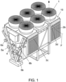
- the apparatus according to the invention illustrated in Figure 1 , comprises a framework 10 above which a fan assembly 1 is mounted which sucks cooling air (arrow F in Figure 1 ) through adiabatic panels 2a and 2b.
- the fluid to be cooled in the heat exchange packs enters through inlets 5a, 5b of the apparatus of Figure 1 and exits through outlets 6a, 6b.
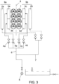
- the diagram of the cooling system of the heat exchange packs illustrated in Figure 2 comprises said fans 1, which pre-cool air sucked by the fans by contact with the wet surface of said packs.
- Spraying units are also provided, consisting of pipes 3a,3b,3c,3d which bear respective spraying nozzles for spraying water to cool the heat exchange packs.
- Respective valves 4a,4b,4c,4d control the water delivery to the cited spraying units 3a, 3b, 3c, 3d. It should be noted that the invention is not limited to the four spraying units shown in the figures, since the number of these units can vary from two or more.
- Cooling water is supplied through an inlet 5 and is split into a branch 6, conveying cooling water to the valves 4a-4d, and a branch 7 conveying water to the adiabatic panels 2.
- a first cooling mode of the heat exchange packs of the apparatus in Figure 1 the cooling is carried out in a dry condition, namely by circulation of air by the fans 1 only ( Figure 3 ).
- cooling by passage of water through the adiabatic panels 2a, 2b is added to the circulation of air by the fans 1 ( Figure 4 ).
- the operating sequence with rotation cycle of said spraying units 3a, 3b, 3c, 3d is performed in such a way that, when only one adiabatic panel is operating, at least one spraying unit 3a, 3b, 3c, 3d is simultaneously activated on the side of the apparatus opposite to the side on which said adiabatic panel is located.
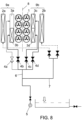
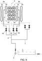
- the cooling action of the fans 1 and the adiabatic panels 2a, 2b is integrated with the action performed by three spraying units, i.e. the units 3b, 3c, 3d, respectively, in the version illustrated in Figure 8 , and the units 3a, 3c, 3d in the version of Figure 9 .
- the operating modes illustrated in said Figures 8 and 9 are rotated by opening the valves 4b, 4c, 4d and 4a, 4c, 4d, respectively.
- the intervention of the different cooling modes described above can be determined as a function of the specific requirements of the cooling system, based on the overall operating time of the spraying units, or also based on the modes required for the specific intended use of the system.
- the number of spraying units and related valves could be different.
- the presence of the adiabatic panels, for example, is not necessary since the cooling system according to the invention can achieve the claimed effects also through the spraying units 3a-3d only, operating in rotation.
- a system (not illustrated) can be provided for controlling the duration times of the described operating modes of the apparatus, in particular of said spraying units, adjusted based on the required cooling needs.
Landscapes
- Engineering & Computer Science (AREA)
- Physics & Mathematics (AREA)
- Thermal Sciences (AREA)
- Mechanical Engineering (AREA)
- General Engineering & Computer Science (AREA)
- Telephonic Communication Services (AREA)
- Heat Treatment Of Strip Materials And Filament Materials (AREA)
- Devices That Are Associated With Refrigeration Equipment (AREA)
- Processing Of Solid Wastes (AREA)
Description
- The present invention concerns an improved cooling process and the related cooling apparatus.
- The field of the invention is that of systems for cooling single-phase or two-phase fluids, in turn used in refrigerating or conditioning systems, or in industrial heat exchange systems.
- The systems to which the invention refers are in particular of the type provided with ducts for the fluid to be cooled, which enters a heat exchange pack where it is cooled by means of an air circulation provided by respective fans and by means of adiabatic panels that pre-cool air sucked by fans through the heat exchange pack, and by means of spray nozzles wetting the surface of the heat exchange pack with water.
- In the prior art relative to exchangers described here (
EP3306247A1 ), the above-mentioned components are activated only as a function of the exchange power required. This has the drawback of keeping constantly in operation the same initial cooling area of the exchanger, in which the corresponding adiabatic pack is the one that receives the spraying action for the longest period of time. As a result, the adiabatic pack where the initial cooling takes place is subjected to the highest number of working hours and is therefore more liable to malfunctions and requires more frequent maintenance to remove residues (limescale and similar) left by the cooling water. - The main aim of the invention is to provide a cooling process, and the related apparatus, adapted to avoid the above-mentioned drawbacks.
- This aim is achieved by the process and apparatus of
claims - According to the invention, the spray nozzles for cooling the adiabatic packs are activated alternately, namely in a rotation cycle sequence in which the spray nozzles operate in alternate phases. In this way, while in a first phase some spray nozzles are active and others are at rest, in the subsequent phases this operating state is varied or exchanged between the spray nozzles within the overall cooling system.
- In the process and apparatus according to the invention, the components that perform the cooling are therefore no longer activated only as a function of the exchange power required, but also taking into account the operating time of the spray nozzles. In this way there is an exchange between different zones or cooling areas of the apparatus according to the invention, which are therefore each subjected to a shorter period of use, with evident advantages in terms of maintenance and good overall operation of the system.
- This and other objects are achieved by the process and apparatus of the present invention, illustrated by way of non-limiting example in the figures of the attached drawings, wherein:
-
Figure 1 schematically illustrates an example of a cooling apparatus according to the invention, -
Figure 2 schematically illustrates the operating principle of the cooling system provided on the apparatus ofFigure 1 ; -
Figure 3 illustrates the dry operation diagram of the system inFigure 2 ; -
Figure 4 illustrates the diagram ofFigure 2 , in a dry operation state in combination with pre-cooling of air on both the adiabatic panels; -
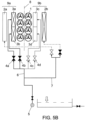
Figures 5A ,5B illustrate the diagram ofFigure 2 , in operation with fans, in combination with one single adiabatic panel on one side of the cooling apparatus and with one and two spraying units, respectively, on the opposite side; -
Figures 6 and7 illustrate the operation diagram ofFigure 2 , with rotating operation of two spraying units on both sides of the apparatus; -
Figures 8 and9 illustrate the diagram ofFigure 2 , with rotating operation of three spraying units; and -
Figure 10 illustrates the diagram ofFigure 2 with full operation of the cooling system (fans, plus adiabatic panels, plus all the spraying units). - The apparatus according to the invention, illustrated in
Figure 1 , comprises aframework 10 above which afan assembly 1 is mounted which sucks cooling air (arrow F inFigure 1 ) throughadiabatic panels inlets Figure 1 and exits throughoutlets - The diagram of the cooling system of the heat exchange packs illustrated in
Figure 2 comprises saidfans 1, which pre-cool air sucked by the fans by contact with the wet surface of said packs. Spraying units are also provided, consisting ofpipes Respective valves spraying units - Cooling water is supplied through an
inlet 5 and is split into abranch 6, conveying cooling water to thevalves 4a-4d, and abranch 7 conveying water to the adiabatic panels 2. - In a first cooling mode of the heat exchange packs of the apparatus in
Figure 1 , the cooling is carried out in a dry condition, namely by circulation of air by thefans 1 only (Figure 3 ). - In a second mode, cooling by passage of water through the
adiabatic panels Figure 4 ). - In the cooling mode illustrated in
Figures 5A and5B , with the cooling apparatus split into two sides orparts centre line 8, the cooling action performed by thespraying unit 3a located on theside 9a of the cooling apparatus (Figure 5A ) or by both thespraying units same side 9a, by opening of therespective valves Figure 5B ), is added to the cooling action of thefans 1 and the singleadiabatic panel 2b located on theside 9b of the apparatus. The principle is to obtain a higher cooling level than that illustrated inFigure 4 , by introducing the operation of one or two spraying units on one side of the cooling apparatus, while maintaining on the opposite side the cooling action due to the respective adiabatic panel. - More specifically, the operating sequence with rotation cycle of said
spraying units spraying unit - In the cooling mode illustrated in
Figures 6 and7 , the cooling action due to the activation of a spraying unit on bothsides unit 3b on theside 9a and theunit 3c or theunit 3d on theside 9b of the same cooling apparatus, respectively, is added to the cooling action of thefans 1 and both theadiabatic panels Figures 6 and7 described above is obtained by opening thevalves - In this phase, therefore, the
spraying unit 3a, which in the preceding phases was in operating state, is now kept turned off, while theremaining units - In the operating modes illustrated in
Figures 8 and9 , the cooling action of thefans 1 and theadiabatic panels units Figure 8 , and theunits Figure 9 . Also in this case, and according to the invention, the operating modes illustrated in saidFigures 8 and9 are rotated by opening thevalves - The most complete or highest cooling level is obtained in the mode illustrated in
Figure 10 , where the cooling is provided together by thefans 1, theadiabatic panels spraying units - The intervention of the different cooling modes described above can be determined as a function of the specific requirements of the cooling system, based on the overall operating time of the spraying units, or also based on the modes required for the specific intended use of the system.
- Modifications can be made to the invention, as described above and illustrated in the figures of the attached drawings, in order to provide variations, which anyway fall within the protective scope defined in the appended claims.
- Thus, for example, the number of spraying units and related valves could be different. Furthermore, the presence of the adiabatic panels, for example, is not necessary since the cooling system according to the invention can achieve the claimed effects also through the
spraying units 3a-3d only, operating in rotation. - It is furthermore possible to provide for rotation of only one single spraying unit, moving it between the various sectors. Thus, for example, it is possible to cool by individually activating the
spraying units - Finally, a system (not illustrated) can be provided for controlling the duration times of the described operating modes of the apparatus, in particular of said spraying units, adjusted based on the required cooling needs.
Claims (4)
- A process for cooling a fluid with an apparatus comprising spraying units (3) controlled by respective supply valves (4) for supplying a heat-carrier fluid, characterized in that said spraying units (3) are activated in a mutually alternating way according to an operation sequence with a rotation cycle between them and in that said spraying units (3) are activated with alternating operation between individual spraying units and/or sets of two or more spraying units.
- The process according to claim 1, characterized in that said apparatus further comprises cooling air circulation fans (1) and adiabatic panels (2), characterized in that it provides for the activation of said fans (1) and said panels (2) in combination with said spraying units (3) with an alternating operation sequence or according to a rotation cycle between them.
- The process according to claim 2, characterized in that said operation sequence of said spraying units (3) according to a rotation cycle operates in such a way that, divided the cooling apparatus into two sides (9a, 9b) separated by a centre line (8), when only one adiabatic panel (2) on one of said sides (9a) or (9b) is operating, at least one spraying unit (3) is simultaneously activated on the other side of the apparatus, opposite to the side on which said adiabatic panel (2) is located.
- A cooling apparatus for implementing the process according to one or more of the preceding claims, comprising fans (1), adiabatic panels (2), and spraying units (3), controlled by respective valves (4), for spraying water on the heat-exchange packs of said apparatus, wherein said panels (2) are located distributed on the parts (9a, 9b) of said apparatus, characterized in that it provides a control system for the duration times of said operating modes according to a rotation cycle of said spraying units, adjusted based on the required cooling needs, wherein said spraying units (3) are activated with alternating operation between individual spraying units and/or sets of two or more spraying units.
Priority Applications (1)
| Application Number | Priority Date | Filing Date | Title |
|---|---|---|---|
| RS20230353A RS64187B2 (en) | 2018-12-17 | 2019-12-16 | Improved cooling process and apparatus for implementing said process |
Applications Claiming Priority (1)
| Application Number | Priority Date | Filing Date | Title |
|---|---|---|---|
| IT102018000011172A IT201800011172A1 (en) | 2018-12-17 | 2018-12-17 | COOLING PROCEDURE OF A PERFECTED TYPE AND DEVICE FOR THE IMPLEMENTATION OF THE SAID PROCEDURE. |
Publications (3)
| Publication Number | Publication Date |
|---|---|
| EP3671090A1 EP3671090A1 (en) | 2020-06-24 |
| EP3671090B1 true EP3671090B1 (en) | 2023-04-05 |
| EP3671090B2 EP3671090B2 (en) | 2025-11-19 |
Family
ID=66166280
Family Applications (1)
| Application Number | Title | Priority Date | Filing Date |
|---|---|---|---|
| EP19216451.5A Active EP3671090B2 (en) | 2018-12-17 | 2019-12-16 | Improved cooling process and apparatus for implementing said process |
Country Status (6)
| Country | Link |
|---|---|
| EP (1) | EP3671090B2 (en) |
| ES (1) | ES2943497T5 (en) |
| HU (1) | HUE061612T2 (en) |
| IT (1) | IT201800011172A1 (en) |
| PT (1) | PT3671090T (en) |
| RS (1) | RS64187B2 (en) |
Families Citing this family (2)
| Publication number | Priority date | Publication date | Assignee | Title |
|---|---|---|---|---|
| LV15791A (en) | 2022-05-02 | 2023-11-20 | STRELITS-STRĒLE Jānis | Adiabatic precooling system for V-type air-cooled heat exchanger |
| WO2025254505A1 (en) | 2025-02-20 | 2025-12-11 | Blue Energy Global, SIA | An air-cooled heat exchanger system with improved water drainage |
Citations (7)
| Publication number | Priority date | Publication date | Assignee | Title |
|---|---|---|---|---|
| CH693043A5 (en) | 1998-05-11 | 2003-01-31 | Armin Schnetzler | Plant for cooling fluid with trickle structure formed by lamella packet or lamella inserts |
| EP2696159A1 (en) | 2012-08-09 | 2014-02-12 | A-heat Allied Heat Exchange Technology Ag | Heat exchanger and method for wetting heat exchangers |
| US20150021796A1 (en) | 2013-07-19 | 2015-01-22 | Honeywell International Inc. | Methods, systems, and devices for humidifying |
| US20150204554A1 (en) | 2014-01-17 | 2015-07-23 | Dri-Steem Corporation | Staged dry out control for evaporative media systems |
| WO2015173767A1 (en) | 2014-05-15 | 2015-11-19 | Frigel Firenze S.P.A. | Combined convector |
| EP3002530A1 (en) | 2014-10-03 | 2016-04-06 | Güntner GmbH & Co. KG | Heat exchanger, heat exchanger device and method for wetting a heat exchanger |
| EP3306247A1 (en) | 2016-10-05 | 2018-04-11 | Lu-Ve S.P.A. | Air-water heat exchanger structure and method for controlling and enhancing the operation thereof |
Family Cites Families (1)
| Publication number | Priority date | Publication date | Assignee | Title |
|---|---|---|---|---|
| WO2018148460A1 (en) * | 2017-02-08 | 2018-08-16 | Evapco, Inc. | Modulated water flow for once-through adiabatic cooling |
-
2018
- 2018-12-17 IT IT102018000011172A patent/IT201800011172A1/en unknown
-
2019
- 2019-12-16 ES ES19216451T patent/ES2943497T5/en active Active
- 2019-12-16 EP EP19216451.5A patent/EP3671090B2/en active Active
- 2019-12-16 HU HUE19216451A patent/HUE061612T2/en unknown
- 2019-12-16 RS RS20230353A patent/RS64187B2/en unknown
- 2019-12-16 PT PT192164515T patent/PT3671090T/en unknown
Patent Citations (7)
| Publication number | Priority date | Publication date | Assignee | Title |
|---|---|---|---|---|
| CH693043A5 (en) | 1998-05-11 | 2003-01-31 | Armin Schnetzler | Plant for cooling fluid with trickle structure formed by lamella packet or lamella inserts |
| EP2696159A1 (en) | 2012-08-09 | 2014-02-12 | A-heat Allied Heat Exchange Technology Ag | Heat exchanger and method for wetting heat exchangers |
| US20150021796A1 (en) | 2013-07-19 | 2015-01-22 | Honeywell International Inc. | Methods, systems, and devices for humidifying |
| US20150204554A1 (en) | 2014-01-17 | 2015-07-23 | Dri-Steem Corporation | Staged dry out control for evaporative media systems |
| WO2015173767A1 (en) | 2014-05-15 | 2015-11-19 | Frigel Firenze S.P.A. | Combined convector |
| EP3002530A1 (en) | 2014-10-03 | 2016-04-06 | Güntner GmbH & Co. KG | Heat exchanger, heat exchanger device and method for wetting a heat exchanger |
| EP3306247A1 (en) | 2016-10-05 | 2018-04-11 | Lu-Ve S.P.A. | Air-water heat exchanger structure and method for controlling and enhancing the operation thereof |
Also Published As
| Publication number | Publication date |
|---|---|
| ES2943497T3 (en) | 2023-06-13 |
| IT201800011172A1 (en) | 2020-06-17 |
| PT3671090T (en) | 2023-07-04 |
| ES2943497T5 (en) | 2026-02-19 |
| RS64187B2 (en) | 2026-03-31 |
| HUE061612T2 (en) | 2023-07-28 |
| EP3671090B2 (en) | 2025-11-19 |
| RS64187B1 (en) | 2023-06-30 |
| EP3671090A1 (en) | 2020-06-24 |
Similar Documents
| Publication | Publication Date | Title |
|---|---|---|
| EP3671090B1 (en) | Improved cooling process and apparatus for implementing said process | |
| JP5363212B2 (en) | Air conditioning system | |
| JPH0221139A (en) | Indirect type air conditioner | |
| JP6324657B2 (en) | Food cooling system | |
| JP7555238B2 (en) | Chiller System | |
| CN106255858B (en) | Mix heat-pump apparatus | |
| US20110314847A1 (en) | Dual duty compression machine | |
| EP3225926B1 (en) | Evaporation heat exchange device for air cooling for conditioning and climate control systems for server rooms and the like | |
| JP6590983B2 (en) | Heat source integrated system air conditioner | |
| JP2017089966A (en) | Refrigeration machine compound type indirect evaporative air conditioner and refrigeration machine compound type indirect evaporative air conditioning method | |
| CN112011444B (en) | Ventilation type koji making device | |
| KR101506844B1 (en) | Vacuum drying system of agricultural and marine products | |
| US10634394B2 (en) | Air conditioner outdoor unit including heat exchange apparatus | |
| KR100474910B1 (en) | method for controling cooling system with two evaporators | |
| CN204923558U (en) | Multi-split system | |
| JPH02290484A (en) | Operating method of cooling apparatus | |
| EP2211125A1 (en) | Plant and process for producing cold and for producing hot water to be supplied to one or more thermal users | |
| JPH09196544A (en) | Humidification cooling adjuster for refrigerator | |
| JP2014240718A (en) | Ventilation system | |
| Avsyukevich | Exergoeconomic model of a central air conditioning system. | |
| KR101641245B1 (en) | Chiller | |
| CN215216530U (en) | Temperature control system | |
| JP2024064811A (en) | Chiller system and method for controlling chiller system | |
| SU1305503A1 (en) | Air conditioning system with waste heat enegry recovery | |
| JPH0570069B2 (en) |
Legal Events
| Date | Code | Title | Description |
|---|---|---|---|
| PUAI | Public reference made under article 153(3) epc to a published international application that has entered the european phase |
Free format text: ORIGINAL CODE: 0009012 |
|
| STAA | Information on the status of an ep patent application or granted ep patent |
Free format text: STATUS: THE APPLICATION HAS BEEN PUBLISHED |
|
| AK | Designated contracting states |
Kind code of ref document: A1 Designated state(s): AL AT BE BG CH CY CZ DE DK EE ES FI FR GB GR HR HU IE IS IT LI LT LU LV MC MK MT NL NO PL PT RO RS SE SI SK SM TR |
|
| AX | Request for extension of the european patent |
Extension state: BA ME |
|
| STAA | Information on the status of an ep patent application or granted ep patent |
Free format text: STATUS: REQUEST FOR EXAMINATION WAS MADE |
|
| 17P | Request for examination filed |
Effective date: 20201221 |
|
| STAA | Information on the status of an ep patent application or granted ep patent |
Free format text: STATUS: EXAMINATION IS IN PROGRESS |
|
| 17Q | First examination report despatched |
Effective date: 20220414 |
|
| GRAP | Despatch of communication of intention to grant a patent |
Free format text: ORIGINAL CODE: EPIDOSNIGR1 |
|
| STAA | Information on the status of an ep patent application or granted ep patent |
Free format text: STATUS: GRANT OF PATENT IS INTENDED |
|
| INTG | Intention to grant announced |
Effective date: 20221116 |
|
| GRAS | Grant fee paid |
Free format text: ORIGINAL CODE: EPIDOSNIGR3 |
|
| GRAA | (expected) grant |
Free format text: ORIGINAL CODE: 0009210 |
|
| STAA | Information on the status of an ep patent application or granted ep patent |
Free format text: STATUS: THE PATENT HAS BEEN GRANTED |
|
| AK | Designated contracting states |
Kind code of ref document: B1 Designated state(s): AL AT BE BG CH CY CZ DE DK EE ES FI FR GB GR HR HU IE IS IT LI LT LU LV MC MK MT NL NO PL PT RO RS SE SI SK SM TR |
|
| REG | Reference to a national code |
Ref country code: GB Ref legal event code: FG4D |
|
| REG | Reference to a national code |
Ref country code: DE Ref legal event code: R096 Ref document number: 602019027146 Country of ref document: DE |
|
| REG | Reference to a national code |
Ref country code: CH Ref legal event code: EP |
|
| REG | Reference to a national code |
Ref country code: AT Ref legal event code: REF Ref document number: 1558522 Country of ref document: AT Kind code of ref document: T Effective date: 20230415 |
|
| REG | Reference to a national code |
Ref country code: IE Ref legal event code: FG4D |
|
| REG | Reference to a national code |
Ref country code: SE Ref legal event code: TRGR |
|
| REG | Reference to a national code |
Ref country code: NL Ref legal event code: FP |
|
| REG | Reference to a national code |
Ref country code: ES Ref legal event code: FG2A Ref document number: 2943497 Country of ref document: ES Kind code of ref document: T3 Effective date: 20230613 |
|
| P01 | Opt-out of the competence of the unified patent court (upc) registered |
Effective date: 20230411 |
|
| REG | Reference to a national code |
Ref country code: PT Ref legal event code: SC4A Ref document number: 3671090 Country of ref document: PT Date of ref document: 20230704 Kind code of ref document: T Free format text: AVAILABILITY OF NATIONAL TRANSLATION Effective date: 20230628 |
|
| REG | Reference to a national code |
Ref country code: LT Ref legal event code: MG9D |
|
| REG | Reference to a national code |
Ref country code: HU Ref legal event code: AG4A Ref document number: E061612 Country of ref document: HU |
|
| REG | Reference to a national code |
Ref country code: AT Ref legal event code: MK05 Ref document number: 1558522 Country of ref document: AT Kind code of ref document: T Effective date: 20230405 |
|
| PG25 | Lapsed in a contracting state [announced via postgrant information from national office to epo] |
Ref country code: NO Free format text: LAPSE BECAUSE OF FAILURE TO SUBMIT A TRANSLATION OF THE DESCRIPTION OR TO PAY THE FEE WITHIN THE PRESCRIBED TIME-LIMIT Effective date: 20230705 Ref country code: AT Free format text: LAPSE BECAUSE OF FAILURE TO SUBMIT A TRANSLATION OF THE DESCRIPTION OR TO PAY THE FEE WITHIN THE PRESCRIBED TIME-LIMIT Effective date: 20230405 |
|
| PG25 | Lapsed in a contracting state [announced via postgrant information from national office to epo] |
Ref country code: PL Free format text: LAPSE BECAUSE OF FAILURE TO SUBMIT A TRANSLATION OF THE DESCRIPTION OR TO PAY THE FEE WITHIN THE PRESCRIBED TIME-LIMIT Effective date: 20230405 Ref country code: LV Free format text: LAPSE BECAUSE OF FAILURE TO SUBMIT A TRANSLATION OF THE DESCRIPTION OR TO PAY THE FEE WITHIN THE PRESCRIBED TIME-LIMIT Effective date: 20230405 Ref country code: LT Free format text: LAPSE BECAUSE OF FAILURE TO SUBMIT A TRANSLATION OF THE DESCRIPTION OR TO PAY THE FEE WITHIN THE PRESCRIBED TIME-LIMIT Effective date: 20230405 Ref country code: IS Free format text: LAPSE BECAUSE OF FAILURE TO SUBMIT A TRANSLATION OF THE DESCRIPTION OR TO PAY THE FEE WITHIN THE PRESCRIBED TIME-LIMIT Effective date: 20230805 Ref country code: HR Free format text: LAPSE BECAUSE OF FAILURE TO SUBMIT A TRANSLATION OF THE DESCRIPTION OR TO PAY THE FEE WITHIN THE PRESCRIBED TIME-LIMIT Effective date: 20230405 Ref country code: GR Free format text: LAPSE BECAUSE OF FAILURE TO SUBMIT A TRANSLATION OF THE DESCRIPTION OR TO PAY THE FEE WITHIN THE PRESCRIBED TIME-LIMIT Effective date: 20230706 |
|
| PG25 | Lapsed in a contracting state [announced via postgrant information from national office to epo] |
Ref country code: FI Free format text: LAPSE BECAUSE OF FAILURE TO SUBMIT A TRANSLATION OF THE DESCRIPTION OR TO PAY THE FEE WITHIN THE PRESCRIBED TIME-LIMIT Effective date: 20230405 |
|
| REG | Reference to a national code |
Ref country code: DE Ref legal event code: R026 Ref document number: 602019027146 Country of ref document: DE |
|
| PLBI | Opposition filed |
Free format text: ORIGINAL CODE: 0009260 |
|
| PG25 | Lapsed in a contracting state [announced via postgrant information from national office to epo] |
Ref country code: SK Free format text: LAPSE BECAUSE OF FAILURE TO SUBMIT A TRANSLATION OF THE DESCRIPTION OR TO PAY THE FEE WITHIN THE PRESCRIBED TIME-LIMIT Effective date: 20230405 |
|
| PLAX | Notice of opposition and request to file observation + time limit sent |
Free format text: ORIGINAL CODE: EPIDOSNOBS2 |
|
| PG25 | Lapsed in a contracting state [announced via postgrant information from national office to epo] |
Ref country code: SM Free format text: LAPSE BECAUSE OF FAILURE TO SUBMIT A TRANSLATION OF THE DESCRIPTION OR TO PAY THE FEE WITHIN THE PRESCRIBED TIME-LIMIT Effective date: 20230405 Ref country code: SK Free format text: LAPSE BECAUSE OF FAILURE TO SUBMIT A TRANSLATION OF THE DESCRIPTION OR TO PAY THE FEE WITHIN THE PRESCRIBED TIME-LIMIT Effective date: 20230405 Ref country code: EE Free format text: LAPSE BECAUSE OF FAILURE TO SUBMIT A TRANSLATION OF THE DESCRIPTION OR TO PAY THE FEE WITHIN THE PRESCRIBED TIME-LIMIT Effective date: 20230405 Ref country code: DK Free format text: LAPSE BECAUSE OF FAILURE TO SUBMIT A TRANSLATION OF THE DESCRIPTION OR TO PAY THE FEE WITHIN THE PRESCRIBED TIME-LIMIT Effective date: 20230405 Ref country code: CZ Free format text: LAPSE BECAUSE OF FAILURE TO SUBMIT A TRANSLATION OF THE DESCRIPTION OR TO PAY THE FEE WITHIN THE PRESCRIBED TIME-LIMIT Effective date: 20230405 |
|
| 26 | Opposition filed |
Opponent name: GUENTNER GMBH & CO. KG Effective date: 20240103 |
|
| PG25 | Lapsed in a contracting state [announced via postgrant information from national office to epo] |
Ref country code: SI Free format text: LAPSE BECAUSE OF FAILURE TO SUBMIT A TRANSLATION OF THE DESCRIPTION OR TO PAY THE FEE WITHIN THE PRESCRIBED TIME-LIMIT Effective date: 20230405 |
|
| PLBB | Reply of patent proprietor to notice(s) of opposition received |
Free format text: ORIGINAL CODE: EPIDOSNOBS3 |
|
| PG25 | Lapsed in a contracting state [announced via postgrant information from national office to epo] |
Ref country code: SI Free format text: LAPSE BECAUSE OF FAILURE TO SUBMIT A TRANSLATION OF THE DESCRIPTION OR TO PAY THE FEE WITHIN THE PRESCRIBED TIME-LIMIT Effective date: 20230405 |
|
| REG | Reference to a national code |
Ref country code: CH Ref legal event code: PL |
|
| PG25 | Lapsed in a contracting state [announced via postgrant information from national office to epo] |
Ref country code: LU Free format text: LAPSE BECAUSE OF NON-PAYMENT OF DUE FEES Effective date: 20231216 |
|
| PG25 | Lapsed in a contracting state [announced via postgrant information from national office to epo] |
Ref country code: MC Free format text: LAPSE BECAUSE OF FAILURE TO SUBMIT A TRANSLATION OF THE DESCRIPTION OR TO PAY THE FEE WITHIN THE PRESCRIBED TIME-LIMIT Effective date: 20230405 |
|
| PG25 | Lapsed in a contracting state [announced via postgrant information from national office to epo] |
Ref country code: MC Free format text: LAPSE BECAUSE OF FAILURE TO SUBMIT A TRANSLATION OF THE DESCRIPTION OR TO PAY THE FEE WITHIN THE PRESCRIBED TIME-LIMIT Effective date: 20230405 Ref country code: LU Free format text: LAPSE BECAUSE OF NON-PAYMENT OF DUE FEES Effective date: 20231216 |
|
| REG | Reference to a national code |
Ref country code: IE Ref legal event code: MM4A |
|
| PG25 | Lapsed in a contracting state [announced via postgrant information from national office to epo] |
Ref country code: IE Free format text: LAPSE BECAUSE OF NON-PAYMENT OF DUE FEES Effective date: 20231216 |
|
| PLAB | Opposition data, opponent's data or that of the opponent's representative modified |
Free format text: ORIGINAL CODE: 0009299OPPO |
|
| PG25 | Lapsed in a contracting state [announced via postgrant information from national office to epo] |
Ref country code: CH Free format text: LAPSE BECAUSE OF NON-PAYMENT OF DUE FEES Effective date: 20231231 |
|
| PG25 | Lapsed in a contracting state [announced via postgrant information from national office to epo] |
Ref country code: IE Free format text: LAPSE BECAUSE OF NON-PAYMENT OF DUE FEES Effective date: 20231216 Ref country code: CH Free format text: LAPSE BECAUSE OF NON-PAYMENT OF DUE FEES Effective date: 20231231 |
|
| PG25 | Lapsed in a contracting state [announced via postgrant information from national office to epo] |
Ref country code: BG Free format text: LAPSE BECAUSE OF FAILURE TO SUBMIT A TRANSLATION OF THE DESCRIPTION OR TO PAY THE FEE WITHIN THE PRESCRIBED TIME-LIMIT Effective date: 20230405 |
|
| R26 | Opposition filed (corrected) |
Opponent name: GUENTNER GMBH & CO. KG Effective date: 20240103 |
|
| PG25 | Lapsed in a contracting state [announced via postgrant information from national office to epo] |
Ref country code: BG Free format text: LAPSE BECAUSE OF FAILURE TO SUBMIT A TRANSLATION OF THE DESCRIPTION OR TO PAY THE FEE WITHIN THE PRESCRIBED TIME-LIMIT Effective date: 20230405 |
|
| PG25 | Lapsed in a contracting state [announced via postgrant information from national office to epo] |
Ref country code: CY Free format text: LAPSE BECAUSE OF FAILURE TO SUBMIT A TRANSLATION OF THE DESCRIPTION OR TO PAY THE FEE WITHIN THE PRESCRIBED TIME-LIMIT; INVALID AB INITIO Effective date: 20191216 |
|
| PUAH | Patent maintained in amended form |
Free format text: ORIGINAL CODE: 0009272 |
|
| STAA | Information on the status of an ep patent application or granted ep patent |
Free format text: STATUS: PATENT MAINTAINED AS AMENDED |
|
| REG | Reference to a national code |
Ref country code: CH Ref legal event code: M12 Free format text: ST27 STATUS EVENT CODE: U-0-0-M10-M12 (AS PROVIDED BY THE NATIONAL OFFICE) Effective date: 20251022 |
|
| 27A | Patent maintained in amended form |
Effective date: 20251119 |
|
| AK | Designated contracting states |
Kind code of ref document: B2 Designated state(s): AL AT BE BG CH CY CZ DE DK EE ES FI FR GB GR HR HU IE IS IT LI LT LU LV MC MK MT NL NO PL PT RO RS SE SI SK SM TR |
|
| REG | Reference to a national code |
Ref country code: DE Ref legal event code: R102 Ref document number: 602019027146 Country of ref document: DE |
|
| REG | Reference to a national code |
Ref country code: NL Ref legal event code: FP |
|
| REG | Reference to a national code |
Ref country code: SE Ref legal event code: RPEO |
|
| PGFP | Annual fee paid to national office [announced via postgrant information from national office to epo] |
Ref country code: GB Payment date: 20251202 Year of fee payment: 7 |
|
| PGFP | Annual fee paid to national office [announced via postgrant information from national office to epo] |
Ref country code: PT Payment date: 20251211 Year of fee payment: 7 |
|
| PGFP | Annual fee paid to national office [announced via postgrant information from national office to epo] |
Ref country code: IT Payment date: 20251212 Year of fee payment: 7 |
|
| PGFP | Annual fee paid to national office [announced via postgrant information from national office to epo] |
Ref country code: HU Payment date: 20251212 Year of fee payment: 7 Ref country code: NL Payment date: 20251212 Year of fee payment: 7 Ref country code: FR Payment date: 20251202 Year of fee payment: 7 |
|
| PGFP | Annual fee paid to national office [announced via postgrant information from national office to epo] |
Ref country code: TR Payment date: 20251203 Year of fee payment: 7 Ref country code: BE Payment date: 20251222 Year of fee payment: 7 |
|
| PGFP | Annual fee paid to national office [announced via postgrant information from national office to epo] |
Ref country code: SE Payment date: 20251215 Year of fee payment: 7 |
|
| PGFP | Annual fee paid to national office [announced via postgrant information from national office to epo] |
Ref country code: RO Payment date: 20251210 Year of fee payment: 7 |
|
| PGFP | Annual fee paid to national office [announced via postgrant information from national office to epo] |
Ref country code: RS Payment date: 20251202 Year of fee payment: 7 |
|
| REG | Reference to a national code |
Ref country code: ES Ref legal event code: DC2A Ref document number: 2943497 Country of ref document: ES Kind code of ref document: T5 Effective date: 20260219 |
|
| PGFP | Annual fee paid to national office [announced via postgrant information from national office to epo] |
Ref country code: ES Payment date: 20260318 Year of fee payment: 7 |
|
| PGFP | Annual fee paid to national office [announced via postgrant information from national office to epo] |
Ref country code: DE Payment date: 20251231 Year of fee payment: 7 |