EP3671040B1 - Amélioration de la rupture de pulvérisation de carburant - Google Patents
Amélioration de la rupture de pulvérisation de carburant Download PDFInfo
- Publication number
- EP3671040B1 EP3671040B1 EP19217150.2A EP19217150A EP3671040B1 EP 3671040 B1 EP3671040 B1 EP 3671040B1 EP 19217150 A EP19217150 A EP 19217150A EP 3671040 B1 EP3671040 B1 EP 3671040B1
- Authority
- EP
- European Patent Office
- Prior art keywords
- fuel injector
- fuel
- pintle
- combustor
- augmentor
- Prior art date
- Legal status (The legal status is an assumption and is not a legal conclusion. Google has not performed a legal analysis and makes no representation as to the accuracy of the status listed.)
- Active
Links
- 239000000446 fuel Substances 0.000 title claims description 134
- 239000007921 spray Substances 0.000 title description 10
- 238000002347 injection Methods 0.000 claims description 17
- 239000007924 injection Substances 0.000 claims description 17
- 238000002485 combustion reaction Methods 0.000 claims description 10
- 238000000889 atomisation Methods 0.000 description 8
- 239000007788 liquid Substances 0.000 description 8
- 238000011144 upstream manufacturing Methods 0.000 description 8
- 238000000034 method Methods 0.000 description 7
- 230000008569 process Effects 0.000 description 5
- 238000012545 processing Methods 0.000 description 5
- 230000008901 benefit Effects 0.000 description 3
- 230000007246 mechanism Effects 0.000 description 3
- 230000009467 reduction Effects 0.000 description 3
- 230000003068 static effect Effects 0.000 description 3
- 230000008859 change Effects 0.000 description 2
- 239000012530 fluid Substances 0.000 description 2
- 230000015556 catabolic process Effects 0.000 description 1
- 238000004891 communication Methods 0.000 description 1
- 230000006835 compression Effects 0.000 description 1
- 238000007906 compression Methods 0.000 description 1
- 238000012937 correction Methods 0.000 description 1
- 238000010586 diagram Methods 0.000 description 1
- 239000003302 ferromagnetic material Substances 0.000 description 1
- 239000000463 material Substances 0.000 description 1
- 238000005259 measurement Methods 0.000 description 1
- 238000012986 modification Methods 0.000 description 1
- 230000004048 modification Effects 0.000 description 1
- 230000007935 neutral effect Effects 0.000 description 1
- 230000004044 response Effects 0.000 description 1
- 238000005507 spraying Methods 0.000 description 1
Images


Classifications
-
- F—MECHANICAL ENGINEERING; LIGHTING; HEATING; WEAPONS; BLASTING
- F23—COMBUSTION APPARATUS; COMBUSTION PROCESSES
- F23R—GENERATING COMBUSTION PRODUCTS OF HIGH PRESSURE OR HIGH VELOCITY, e.g. GAS-TURBINE COMBUSTION CHAMBERS
- F23R3/00—Continuous combustion chambers using liquid or gaseous fuel
- F23R3/28—Continuous combustion chambers using liquid or gaseous fuel characterised by the fuel supply
-
- F—MECHANICAL ENGINEERING; LIGHTING; HEATING; WEAPONS; BLASTING
- F02—COMBUSTION ENGINES; HOT-GAS OR COMBUSTION-PRODUCT ENGINE PLANTS
- F02C—GAS-TURBINE PLANTS; AIR INTAKES FOR JET-PROPULSION PLANTS; CONTROLLING FUEL SUPPLY IN AIR-BREATHING JET-PROPULSION PLANTS
- F02C7/00—Features, components parts, details or accessories, not provided for in, or of interest apart form groups F02C1/00 - F02C6/00; Air intakes for jet-propulsion plants
- F02C7/22—Fuel supply systems
-
- F—MECHANICAL ENGINEERING; LIGHTING; HEATING; WEAPONS; BLASTING
- F02—COMBUSTION ENGINES; HOT-GAS OR COMBUSTION-PRODUCT ENGINE PLANTS
- F02C—GAS-TURBINE PLANTS; AIR INTAKES FOR JET-PROPULSION PLANTS; CONTROLLING FUEL SUPPLY IN AIR-BREATHING JET-PROPULSION PLANTS
- F02C9/00—Controlling gas-turbine plants; Controlling fuel supply in air- breathing jet-propulsion plants
- F02C9/26—Control of fuel supply
- F02C9/28—Regulating systems responsive to plant or ambient parameters, e.g. temperature, pressure, rotor speed
-
- F—MECHANICAL ENGINEERING; LIGHTING; HEATING; WEAPONS; BLASTING
- F23—COMBUSTION APPARATUS; COMBUSTION PROCESSES
- F23D—BURNERS
- F23D11/00—Burners using a direct spraying action of liquid droplets or vaporised liquid into the combustion space
- F23D11/36—Details, e.g. burner cooling means, noise reduction means
- F23D11/38—Nozzles; Cleaning devices therefor
-
- F—MECHANICAL ENGINEERING; LIGHTING; HEATING; WEAPONS; BLASTING
- F23—COMBUSTION APPARATUS; COMBUSTION PROCESSES
- F23R—GENERATING COMBUSTION PRODUCTS OF HIGH PRESSURE OR HIGH VELOCITY, e.g. GAS-TURBINE COMBUSTION CHAMBERS
- F23R3/00—Continuous combustion chambers using liquid or gaseous fuel
- F23R3/28—Continuous combustion chambers using liquid or gaseous fuel characterised by the fuel supply
- F23R3/34—Feeding into different combustion zones
- F23R3/346—Feeding into different combustion zones for staged combustion
-
- F—MECHANICAL ENGINEERING; LIGHTING; HEATING; WEAPONS; BLASTING
- F05—INDEXING SCHEMES RELATING TO ENGINES OR PUMPS IN VARIOUS SUBCLASSES OF CLASSES F01-F04
- F05D—INDEXING SCHEME FOR ASPECTS RELATING TO NON-POSITIVE-DISPLACEMENT MACHINES OR ENGINES, GAS-TURBINES OR JET-PROPULSION PLANTS
- F05D2220/00—Application
- F05D2220/30—Application in turbines
- F05D2220/32—Application in turbines in gas turbines
-
- F—MECHANICAL ENGINEERING; LIGHTING; HEATING; WEAPONS; BLASTING
- F23—COMBUSTION APPARATUS; COMBUSTION PROCESSES
- F23D—BURNERS
- F23D14/00—Burners for combustion of a gas, e.g. of a gas stored under pressure as a liquid
- F23D14/46—Details, e.g. noise reduction means
- F23D14/70—Baffles or like flow-disturbing devices
-
- F—MECHANICAL ENGINEERING; LIGHTING; HEATING; WEAPONS; BLASTING
- F23—COMBUSTION APPARATUS; COMBUSTION PROCESSES
- F23D—BURNERS
- F23D2900/00—Special features of, or arrangements for burners using fluid fuels or solid fuels suspended in a carrier gas
- F23D2900/14—Special features of gas burners
- F23D2900/14481—Burner nozzles incorporating flow adjusting means
Definitions
- Exemplary embodiments of the present disclosure relate generally to fuel spraying and, in one embodiment, to an enhancement to promote fuel spray breakup.
- a gas turbine engine typically includes a fan section, a compressor section, a combustor section and a turbine section. Air entering the compressor section is compressed and delivered into the combustion section where it is mixed with fuel and ignited to generate a high-energy exhaust gas flow. The high-energy exhaust gas flow expands through the turbine section to drive the compressor and the fan section.
- the compressor section typically includes low and high pressure compressors and the turbine section includes low and high pressure turbines.
- high energy fluids aerodynamically interact with blades and vanes such that air flowing into the gas turbine engine can be compressed.
- high energy fluids such as the products of combustion, aerodynamically interact with blades and vanes in order to expand and to thereby drive compressor and rotor rotation.
- Gas turbine engines typically use fuel injectors to introduce fuel into the combustor section as well as afterburner sections.
- the fuel injectors often employ a multitude of holes or orifices to spray the fuel under pressure into the combustor section.
- the fuel spray is created by hydrodynamic breakdown of a liquid column of fuel into individual droplets through complex primary and secondary breakup mechanisms. These mechanisms depend strongly on the velocities of the liquid and on nearby gas flows. The breakup processes therefore change in location and intensity depending on various operating conditions. Because of this variation, the location and the quality of the fuel spray correspondingly varies substantially over the operating range of the gas turbine engines. The variations in the location and the quality of the fuel spray over the operating range of the gas turbine engines can present challenges to control of the combustion processes at certain conditions.
- US 2012/138710 A1 discloses a hybrid variable area fuel injector.
- EP 2993405 A1 discloses a fuel delivery system for a turbine engine, including a variable orifice jet configured to spray fuel received from a spray bar conduit.
- a fuel injector as claimed in claim 1 is provided.
- the at least one of the first and second ends may be attachable to the fuel injector body such that the pintle body is angled in a first direction or in a second direction, respectively.
- the pintle body may define a shaped aperture and the first and second ends are attachable to the fuel injector body such that fuel exiting the fuel injector body through the injection outlet flows through the shaped aperture.
- the shaped aperture may have one of an elliptical and an angular shape.
- the pintle may have one of a flat, convex and concave shape.
- a combustion chamber of a combustor or an augmentor as claimed in claim 6 is provided.
- a combustor or augmentor of a gas turbine engine as claimed in claim 7 is provided.
- the at least one of the first and second ends may be attachable to the fuel injector body such that the pintle body is angled toward the outlet.
- the at least one of the first and second ends may be attachable to the fuel injector body such that the pintle body is angled toward the inlet.
- a controller may be operably coupled to each fuel injector and configured to control operations of each pintleOperations of the pintle of each fuel injector may be independently controllable in accordance with current combustor conditions.
- the current conditions may include inlet airflow conditions, fuel flow conditions and combustion conditions.
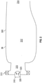
- FIG. 1 schematically illustrates a gas turbine engine 20.
- the gas turbine engine 20 is disclosed herein as a two-spool turbofan that generally incorporates a fan section 22, a compressor section 24, a combustor section 26 and a turbine section 28.
- Alternative engines might include other systems or features.
- the fan section 22 drives air along a bypass flow path B in a bypass duct, while the compressor section 24 drives air along a core flow path C for compression and communication into the combustor section 26 and then expansion through the turbine section 28.
- the exemplary gas turbine engine 20 generally includes a low speed spool 30 and a high speed spool 32 mounted for rotation about an engine central longitudinal axis A relative to an engine static structure 36 via several bearing systems 38. It should be understood that various bearing systems 38 at various locations may alternatively or additionally be provided, and the location of bearing systems 38 may be varied as appropriate to the application.
- the low speed spool 30 generally includes an inner shaft 40 that interconnects a fan 42, a low pressure compressor 44 and a low pressure turbine 46.
- the inner shaft 40 is connected to the fan 42 through a speed change mechanism, which in exemplary gas turbine engine 20 is illustrated as a geared architecture 48 to drive the fan 42 at a lower speed than the low speed spool 30.
- the high speed spool 32 includes an outer shaft 50 that interconnects a high pressure compressor 52 and high pressure turbine 54.
- a combustor 56 is arranged in the gas turbine engine 20 between the high pressure compressor 52 and the high pressure turbine 54.
- the engine static structure 36 is arranged generally between the high pressure turbine 54 and the low pressure turbine 46.
- the engine static structure 36 further supports the bearing systems 38 in the turbine section 28.
- the inner shaft 40 and the outer shaft 50 are concentric and rotate via bearing systems 38 about the engine central longitudinal axis A which is collinear with their longitudinal axes.
- the core airflow is compressed by the low pressure compressor 44 and then the high pressure compressor 52, is mixed and burned with fuel in the combustor 56 and is then expanded over the high pressure turbine 54 and the low pressure turbine 46.
- the high and low pressure turbines 54 and 46 rotationally drive the low speed spool 30 and the high speed spool 32, respectively, in response to the expansion.
- geared architecture 48 may be located aft of the combustor section 26 or even aft of the turbine section 28, and the fan section 22 may be positioned forward or aft of the location of geared architecture 48.
- the gas turbine engine 20 in one example is a high-bypass geared aircraft engine.
- the gas turbine engine 20 bypass ratio is greater than about six (6), with an example embodiment being greater than about ten (10)
- the geared architecture 48 is an epicyclic gear train, such as a planetary gear system or other gear system, with a gear reduction ratio of greater than about 2.3 and the low pressure turbine 46 has a pressure ratio that is greater than about five (5).
- the gas turbine engine 20 bypass ratio is greater than about ten (10:1)
- the fan diameter is significantly larger than that of the low pressure compressor 44
- the low pressure turbine 46 has a pressure ratio that is greater than about five (5:1).
- Low pressure turbine 46 pressure ratio is pressure measured prior to inlet of low pressure turbine 46 as related to the pressure at the outlet of the low pressure turbine 46 prior to an exhaust nozzle.
- the geared architecture 48 may be an epicyclic gear train, such as a planetary gear system or other gear system, with a gear reduction ratio of greater than about 2.3:1. It should be understood, however, that the above parameters are only exemplary of one embodiment of a geared architecture engine and that the present disclosure is applicable to other gas turbine engines including direct drive turbofans.
- the fan section 22 of the gas turbine engine 20 is designed for a particular flight condition--typically cruise at about 0.8 Mach and about 35,000 feet (10,668 meters).
- 'TSFC' Thrust Specific Fuel Consumption
- Low fan pressure ratio is the pressure ratio across the fan blade alone, without a Fan Exit Guide Vane (“FEGV”) system.
- the low fan pressure ratio as disclosed herein according to one non-limiting embodiment is less than about 1.45.
- Low corrected fan tip speed is the actual fan tip speed in ft/sec divided by an industry standard temperature correction of [(Tram °R)/(518.7 °R)] 0.5 .
- the "Low corrected fan tip speed” as disclosed herein according to one non-limiting embodiment is less than about 1150 ft/second (350.5 m/sec).
- a mechanical device in order to force an atomization process of a fuel injector to occur with less variation in quality and position over various operating conditions.
- the mechanical device causes rapid atomization of liquid fuel with less dependence on liquid and gas conditions and, in one embodiment, the mechanical device includes a mechanical pintle at an exit of a fuel injector.
- a jet of liquid fuel impinges on the pintle and the pintle causes the atomization process to occur immediately at the pintle for all operating conditions and assists the atomization process by causing strong velocity gradients in the liquid flow which leads to atomization of the liquid jet.
- the mechanical device uses a shaped injector hole which causes strong velocity gradients in the liquid flow that creates rapid atomization immediately after injection that alters the atomization and also can be less sensitive to operating conditions.
- a combustion chamber or an exemplary combustor 56 of the gas turbine engine 20 that is described above (see FIG. 1 ) is provided and includes a combustor wall 300 and fuel nozzles 310.
- the combustor wall 300 is formed to define a combustor interior 312.
- the combustor interior 312 has an inlet portion 313, an outlet portion 314 and a mixing region 315.
- the mixing region 315 is axially interposed between the inlet portion 313 and the outlet portion 314.
- the inlet portion 313 is receptive of compressed air from the compressor section 24 (see FIG. 1 ). The compressed air flows through the mixing region 315 toward the outlet portion 314.
- the compressed air mixes with fuel that is injected into the mixing region 315 by the fuel nozzle injectors 320 located in the fuel nozzle 310.
- the fuel nozzle injectors 320 are configured to inject fuel into the mixing region 315 via fuel injector openings 323.
- a combustion chamber or an exemplary combustor or augmentor of the gas turbine engine 20 that is described above (see FIG. 1 ) is provided and includes walls 410 and fuel injectors 420 to create a fuel mixing passage.
- the walls 410 are formed to define apertures 411 at various axial and circumferential positions and a mixing section interior 412.
- the mixing section interior 412 has an inlet portion 413, an outlet portion 414 and a mixing region 415.
- the mixing region 415 is axially interposed between the inlet portion 413 and the outlet portion 414.
- the inlet portion 413 is receptive of compressed air from the compressor section 24 (see FIG.
- the air flows through the mixing region 415 toward the outlet portion 414.
- the compressed air mixes with fuel that is injected into the mixing region 415 by the fuel injectors 420.
- the fuel injectors 420 are respectively arrayed along the walls 410 at corresponding apertures 411 and are configured to inject fuel into the mixing region 415.
- each fuel injector 420 includes a fuel injector body 421 and a pintle 422.
- An interior facing side of the fuel injector body 421 abuts with an exterior surface of the wall 410.
- the fuel injector body 421 has an elongate shape that extends outwardly from the exterior surface of the wall 410 and defines an injection outlet 423 through which fuel exits the fuel injector body 421 in a direction oriented toward the mixing region 415.
- the pintle 422 includes a first end 424, a second end 425 and a pintle body 426 that extends between the first end 424 and the second end 425. At least one or both of the first end 424 and the second end 425 is/are attachable to the interior facing side of the fuel injector body 421 to thereby position the pintle body 426 between the injection outlet 423 and the mixing region 415.
- the second end 425 could be attached to the fuel injector body 421 such that the pintle body 426 is angled toward the inlet portion 413 (see FIG. 4 ) or the first end 424 could be attached to the fuel injector body 421 such that the pintle body 426 is angled toward the outlet portion 414 (see FIG. 5 ).
- the pintle body 426 can be formed to define a shaped aperture 427 and both the first end 424 and the second end 425 could be attached to the fuel injector body 421 such that fuel exiting the fuel injector body 421 through the injection outlet 423 flows through the shaped aperture 427.
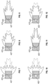
- the shaped aperture 427 can have one of an elliptical shape to provide a resulting jet of atomized fuel with a wide span (see FIG. 7 ) and an angular (e.g., rectangular or triangular) shape to provide the resulting jet of atomized fuel with a neutral width or narrow span (see FIGS. 8 and 9 ).
- the pintle body 426 of the pintle 422 can have one of a flat edge shape to provide a resulting jet of atomized fuel with a wide span (see FIG. 10 ), a convex edge shape to provide the resulting jet of atomized fuel with a narrow, extended span (see FIG. 11 ) and a concave edge shape to provide the resulting jet of atomized fuel with a wide, shortened span (see FIG. 12 ).
- connection point 1401 a point at which the first end 424 or the second end 425 of the pintle 422 attaches to the fuel injector body 421 is defined as a connection point 1401. As shown in FIG. 13 , this connection point 1401 is variable relative to the injection outlet 423 and can be moved toward or away from the injection outlet 423.
- the configuration and operation of the pintle 422 of each of the fuel injectors 420 can be controlled independently from the other pintles 422 in order to condition and control a shape, size and power of a jet of atomized fuel being injected into the mixing region 415.
- the pintles 422 of the fuel injectors 420 which are closer to the inlet portion 413 can be operated so as to assume the configuration illustrated in FIG. 4
- the pintles 422 of the fuel injectors 420 which are closer to the outlet portion 414 can be operated so as to assume the configuration illustrated in FIG. 5 .
- the jets of atomized fuel associated with the fuel injectors 420 closer to the inlet portion 413 will extend further into the center of the combustor interior 412 while the jets of atomized fuel associated with the fuel injectors 420 closer to the outlet portion 414 remain comparatively close to the wall 410.
- the operations of the various pintles 422 can also be modified in accordance with current conditions such as inlet airflow conditions, fuel flow conditions and combustion conditions (i.e., low-load or startup conditions, intermediate-load conditions and high-load or high-demand conditions).
- a controller 1501 can be provided and can be operably coupled to each of the fuel injectors 420 described herein.
- the controller 1501 can be configured to control various operations of each of the pintles 422 in accordance with at least the current conditions.
- the controller 1501 can include a processing unit 1510, a memory unit 1520 and an input/output (I/O) unit 1530 by which the processing unit 1510 is operably communicative with the fuel injectors 420 as well as various control elements and sensors of the gas turbine engine 20 (see FIG. 1 ) that govern and sense operations thereof.
- the memory unit 1520 has executable instructions stored thereon, which are readable and executable by the processing unit 1510. When the executable instructions are read and executed by the processing unit 1510, the executable instructions cause the processing unit 1510 to control the various operations of the fuel injectors 420 by way of the I/O unit 1530.
- the at least one of the first and second ends 424 and 425 of each pintle 422 is electro-magnetically attachable to the fuel injector body 421. That is, if the first end 424 is again defined as the upstream end and the second end 425 is again defined as the downstream end for each pintle 422 and each fuel injector 420, corresponding upstream and downstream sides of the fuel injector body 421 can be defined as upstream and downstream sides 1601 and 1602, respectively.
- the pintle 422 can be formed with ferromagnetic material and the upstream and downstream sides 1601 and 1602 can be provided as electro-magnets that are independently supplied with current by the controller 1501.
- the controller 1501 can deactivate the fuel injector 420 by supplying the upstream and downstream sides 1601 and 1602 with current so as to electro-magnetically attract the first and second ends 424 and 425 toward the upstream and downstream sides 1601 and 1602, respectively. If the pintle body 426 is not found to define a pintle aperture as described above, such attraction will close off the injection outlet 423 and prevent atomized fuel from exiting the fuel injector 420.
- the controller 1501 can also activate the fuel injector 420 by supplying only one of the upstream and downstream sides 1601 and 1602 with current so as to electro-magnetically attract the corresponding one of first and second ends 424 and 425, respectively.
- Benefits of the features described herein are the reduction of variabilities in fuel atomization processes in fuel injectors that will reduce the variabilities in fuel delivery over ranges of operating conditions of gas turbine engines to thus improve an overall operability of the gas turbine engine.
- variations in positions of fuel injection sprays and variations in quality of the fuel injection spray generation, which otherwise occurs with conventional fuel injection methods, will also be reduced.
Landscapes
- Engineering & Computer Science (AREA)
- Chemical & Material Sciences (AREA)
- Combustion & Propulsion (AREA)
- Mechanical Engineering (AREA)
- General Engineering & Computer Science (AREA)
- Fuel-Injection Apparatus (AREA)
Claims (12)
- Injecteur de carburant (420) pour un dispositif de combustion ou un dispositif d'augmentation de turbine à gaz, comprenant :un corps d'injecteur de carburant (421) définissant une sortie d'injection (423) au niveau de laquelle le carburant sort du corps d'injecteur de carburant ; etun pivot (422) comprenant une première extrémité (424), une seconde extrémité (425) et un corps de pivot (426) s'étendant entre les première et seconde extrémités ;dans lequel au moins l'une des première et seconde extrémités (424, 425) peut être fixée au corps d'injecteur de carburant (421) pour positionner le corps de pivot (426) afin d'interagir avec le carburant sortant du corps d'injecteur de carburant (421) par la sortie d'injection (423) ; etcaractérisé en ce qu'au moins l'un parmi :un point de connexion (1401) entre l'au moins une des première et seconde extrémités (424, 425) et le corps d'injecteur de carburant (421) est variable par rapport à la sortie d'injection (423) ; etl'au moins une des première et seconde extrémités (424, 425) peut être fixée électromagnétiquement au corps d'injecteur de carburant (421).
- Injecteur de carburant (420) selon la revendication 1, dans lequel au moins l'une des première et seconde extrémités (424, 425) peut être fixée au corps d'injecteur de carburant (421) de sorte que le corps de pivot (426) est incliné dans une première direction ou dans une seconde direction, respectivement.
- Injecteur de carburant (420) selon la revendication 1 ou 2, dans lequel :le corps de pivot (426) définit une ouverture profilée (427), etles première et seconde extrémités (424, 425) peuvent être fixées au corps d'injecteur de carburant (421) de sorte que le carburant sortant du corps d'injecteur de carburant (421) par la sortie d'injection (423) s'écoule à travers l'ouverture profilée (427).
- Injecteur de carburant (420) selon la revendication 3, dans lequel l'ouverture profilée (427) a une forme elliptique et une forme angulaire.
- Injecteur de carburant (420) selon la revendication 1 ou 2, dans lequel le pivot (422) a l'une parmi une forme plate, convexe et concave.
- Chambre de combustion d'un dispositif de combustion (56) ou d'un dispositif d'augmentation, comprenant l'injecteur de carburant (420) selon une quelconque revendication précédente.
- Dispositif de combustion (56) ou dispositif d'augmentation d'un moteur à turbine à gaz (20), le dispositif de combustion ou le dispositif d'augmentation comprenant :une paroi (410) définissant des ouvertures (411) et un intérieur (412) ayant une entrée (413), une sortie (414) et une zone de mélange (415) entre l'entrée (413) et la sortie (414) ; etdes injecteurs de carburant (420) disposés en réseau respectivement le long de la paroi (410) au niveau d'ouvertures correspondantes (411) pour injecter du carburant dans la zone de mélange (415) ;dans lequel chaque injecteur de carburant comprend un injecteur de carburant (420) selon l'une quelconque des revendications 1 à 5, le corps d'injecteur de carburant (421) de l'injecteur de carburant (420) définissant une sortie d'injection (423) à travers laquelle le carburant sort du corps d'injecteur de carburant (421) vers la zone de mélange, et au moins l'une des première et seconde extrémités (424, 425) du pivot (422) pouvant être fixée au corps d'injecteur de carburant (421) pour positionner le corps de pivot (426) entre le sortie d'injection (423) et la zone de mélange (415).
- Dispositif de combustion (56) ou dispositif d'augmentation selon la revendication 7, dans lequel au moins l'une des première et seconde extrémités (424, 425) du pivot (422) peut être fixée au corps d'injecteur de carburant (421) de sorte que le corps de pivot (426) est incliné vers la sortie (414).
- Dispositif de combustion (56) ou dispositif d'augmentation selon la revendication 7 ou 8, dans lequel au moins l'une des première et seconde extrémités (424, 425) peut être fixée au corps d'injecteur de carburant (421) de sorte que le corps de pivot (426) est incliné vers l'entrée (413).
- Dispositif de combustion (56) ou dispositif d'augmentation selon la revendication 7, 8 ou 9, comprenant en outre un dispositif de commande (1501) couplé de manière fonctionnelle à chaque injecteur de carburant (420) et configuré pour commander des opérations de chaque pivot (422).
- Dispositif de combustion (56) ou dispositif d'augmentation selon l'une quelconque des revendications 7 à 10, comprenant en outre des opérations du pivot (422) de chaque injecteur de carburant (420) pouvant être commandées indépendamment selon les conditions actuelles du dispositif de combustion.
- Dispositif de combustion (56) ou dispositif d'augmentation selon la revendication 11, dans lequel les conditions actuelles comprennent des conditions d'écoulement d'air d'admission, des conditions d'écoulement de carburant et des conditions de combustion.
Applications Claiming Priority (1)
| Application Number | Priority Date | Filing Date | Title |
|---|---|---|---|
| US16/222,568 US10948189B2 (en) | 2018-12-17 | 2018-12-17 | Enhancement for fuel spray breakup |
Publications (2)
| Publication Number | Publication Date |
|---|---|
| EP3671040A1 EP3671040A1 (fr) | 2020-06-24 |
| EP3671040B1 true EP3671040B1 (fr) | 2022-01-26 |
Family
ID=68944310
Family Applications (1)
| Application Number | Title | Priority Date | Filing Date |
|---|---|---|---|
| EP19217150.2A Active EP3671040B1 (fr) | 2018-12-17 | 2019-12-17 | Amélioration de la rupture de pulvérisation de carburant |
Country Status (2)
| Country | Link |
|---|---|
| US (1) | US10948189B2 (fr) |
| EP (1) | EP3671040B1 (fr) |
Family Cites Families (13)
| Publication number | Priority date | Publication date | Assignee | Title |
|---|---|---|---|---|
| US2930192A (en) * | 1953-12-07 | 1960-03-29 | Gen Electric | Reverse vortex combustion chamber |
| US3302399A (en) * | 1964-11-13 | 1967-02-07 | Westinghouse Electric Corp | Hollow conical fuel spray nozzle for pressurized combustion apparatus |
| US4989404A (en) * | 1988-12-12 | 1991-02-05 | Sundstrand Corporation | Turbine engine with high efficiency fuel atomization |
| US5233825A (en) | 1991-02-07 | 1993-08-10 | Sundstrand Corporation | Tangential air blast impingement fuel injected combustor |
| US5265425A (en) | 1991-09-23 | 1993-11-30 | General Electric Company | Aero-slinger combustor |
| JP2003035417A (ja) | 2001-07-24 | 2003-02-07 | Mitsubishi Heavy Ind Ltd | ガスタービン燃焼器のパイロットノズル |
| US9115897B2 (en) | 2008-09-04 | 2015-08-25 | United Technologies Corporation | Gas turbine engine systems and methods involving enhanced fuel dispersion |
| US20120138710A1 (en) | 2010-12-01 | 2012-06-07 | Pratt & Whitney Rocketdyne Inc. | Hybrid Variable Area Fuel Injector With Thermal Protection |
| WO2013115671A1 (fr) | 2012-02-01 | 2013-08-08 | General Electric Company | Buse de carburant liquide pour turbine à gaz et procédé d'injection de carburant dans un dispositif de combustion d'une turbine à gaz |
| US10094352B2 (en) | 2012-02-16 | 2018-10-09 | Delavan Inc. | Swirl impingement prefilming |
| US10907833B2 (en) | 2014-01-24 | 2021-02-02 | Raytheon Technologies Corporation | Axial staged combustor with restricted main fuel injector |
| JP6245057B2 (ja) | 2014-04-30 | 2017-12-13 | 株式会社Ihi | アフタバーナ及び航空機エンジン |
| US10041444B2 (en) | 2014-09-05 | 2018-08-07 | United Technologies Corporation | Variable orifice jet for a turbine engine |
-
2018
- 2018-12-17 US US16/222,568 patent/US10948189B2/en active Active
-
2019
- 2019-12-17 EP EP19217150.2A patent/EP3671040B1/fr active Active
Also Published As
| Publication number | Publication date |
|---|---|
| EP3671040A1 (fr) | 2020-06-24 |
| US20200191396A1 (en) | 2020-06-18 |
| US10948189B2 (en) | 2021-03-16 |
Similar Documents
| Publication | Publication Date | Title |
|---|---|---|
| EP3036422B1 (fr) | Tuyère convergente-divergente à hautes performances | |
| EP3869024B1 (fr) | Buse de conduit de dérivation de moteur à haut rapport de dérivation comprenant une zone de buse contrôlée | |
| US20210040888A1 (en) | Ducted oil scoop for gas turbine engine | |
| US10352570B2 (en) | Turbine engine fuel injection system and methods of assembling the same | |
| RU2605869C2 (ru) | Хвостовой конус для ротационного газотурбинного двигателя с микроструями | |
| EP3587921B1 (fr) | Méthode de contrôle d'injection de carburant dans une chambre de combustion d'un moteur de turbine à gaz | |
| EP2900995B1 (fr) | Moteur à turbine à gaz à engrenages avec une tuyère intégrée à section variable pour réduire le bruit | |
| US20190017470A1 (en) | Convergent divergent exit nozzle for a gas turbine engine | |
| US20160032835A1 (en) | Air-driven particle pulverizer for gas turbine engine cooling fluid system | |
| EP3671040B1 (fr) | Amélioration de la rupture de pulvérisation de carburant | |
| EP3431876B1 (fr) | Coupelle de turbulence pour chambre de combustion d'un moteur de turbine à gaz | |
| EP2962041B1 (fr) | Chambre de combustion de turbine à gaz avec gicleur d'injecteur de carburant à turbulence variable | |
| EP2993405A1 (fr) | Jet d'orifice variable pour un moteur à turbine | |
| EP3054124B1 (fr) | Système de démarrage pour moteur à turbine à gaz à accumulateur assisté et procédés associés | |
| WO2014051669A1 (fr) | Réduction du bruit d'interaction de volet fluide avec un moteur à turbine à engrenages | |
| US11434831B2 (en) | Gas turbine combustor having a plurality of angled vanes circumferentially spaced within the combustor | |
| US10823415B2 (en) | Deflector for combustor of gas turbine engine | |
| EP3121430B1 (fr) | Ensemble de nacelle | |
| US20160356220A1 (en) | Seal plate with fluid bypass control | |
| EP3099976B1 (fr) | Flux de refroidissement pour un panneau principal dans une chambre de combustion de moteur à turbine à gaz | |
| EP3032071B1 (fr) | Commande de carburant pour transition robuste entre états stables de moteur à turbine à gaz | |
| EP4365412A1 (fr) | Passage d'huile intégré à un ressort de compartiment de palier | |
| EP3460226B1 (fr) | Revêtement mobile de bouchon d'échappement |
Legal Events
| Date | Code | Title | Description |
|---|---|---|---|
| PUAI | Public reference made under article 153(3) epc to a published international application that has entered the european phase |
Free format text: ORIGINAL CODE: 0009012 |
|
| STAA | Information on the status of an ep patent application or granted ep patent |
Free format text: STATUS: THE APPLICATION HAS BEEN PUBLISHED |
|
| AK | Designated contracting states |
Kind code of ref document: A1 Designated state(s): AL AT BE BG CH CY CZ DE DK EE ES FI FR GB GR HR HU IE IS IT LI LT LU LV MC MK MT NL NO PL PT RO RS SE SI SK SM TR |
|
| AX | Request for extension of the european patent |
Extension state: BA ME |
|
| STAA | Information on the status of an ep patent application or granted ep patent |
Free format text: STATUS: REQUEST FOR EXAMINATION WAS MADE |
|
| 17P | Request for examination filed |
Effective date: 20201223 |
|
| RBV | Designated contracting states (corrected) |
Designated state(s): AL AT BE BG CH CY CZ DE DK EE ES FI FR GB GR HR HU IE IS IT LI LT LU LV MC MK MT NL NO PL PT RO RS SE SI SK SM TR |
|
| RAP1 | Party data changed (applicant data changed or rights of an application transferred) |
Owner name: RAYTHEON TECHNOLOGIES CORPORATION |
|
| GRAP | Despatch of communication of intention to grant a patent |
Free format text: ORIGINAL CODE: EPIDOSNIGR1 |
|
| STAA | Information on the status of an ep patent application or granted ep patent |
Free format text: STATUS: GRANT OF PATENT IS INTENDED |
|
| INTG | Intention to grant announced |
Effective date: 20210701 |
|
| GRAS | Grant fee paid |
Free format text: ORIGINAL CODE: EPIDOSNIGR3 |
|
| GRAA | (expected) grant |
Free format text: ORIGINAL CODE: 0009210 |
|
| STAA | Information on the status of an ep patent application or granted ep patent |
Free format text: STATUS: THE PATENT HAS BEEN GRANTED |
|
| AK | Designated contracting states |
Kind code of ref document: B1 Designated state(s): AL AT BE BG CH CY CZ DE DK EE ES FI FR GB GR HR HU IE IS IT LI LT LU LV MC MK MT NL NO PL PT RO RS SE SI SK SM TR |
|
| REG | Reference to a national code |
Ref country code: GB Ref legal event code: FG4D |
|
| REG | Reference to a national code |
Ref country code: CH Ref legal event code: EP |
|
| REG | Reference to a national code |
Ref country code: AT Ref legal event code: REF Ref document number: 1465560 Country of ref document: AT Kind code of ref document: T Effective date: 20220215 |
|
| REG | Reference to a national code |
Ref country code: IE Ref legal event code: FG4D |
|
| REG | Reference to a national code |
Ref country code: DE Ref legal event code: R096 Ref document number: 602019011215 Country of ref document: DE |
|
| REG | Reference to a national code |
Ref country code: LT Ref legal event code: MG9D |
|
| REG | Reference to a national code |
Ref country code: NL Ref legal event code: MP Effective date: 20220126 |
|
| REG | Reference to a national code |
Ref country code: AT Ref legal event code: MK05 Ref document number: 1465560 Country of ref document: AT Kind code of ref document: T Effective date: 20220126 |
|
| PG25 | Lapsed in a contracting state [announced via postgrant information from national office to epo] |
Ref country code: NL Free format text: LAPSE BECAUSE OF FAILURE TO SUBMIT A TRANSLATION OF THE DESCRIPTION OR TO PAY THE FEE WITHIN THE PRESCRIBED TIME-LIMIT Effective date: 20220126 |
|
| PG25 | Lapsed in a contracting state [announced via postgrant information from national office to epo] |
Ref country code: SE Free format text: LAPSE BECAUSE OF FAILURE TO SUBMIT A TRANSLATION OF THE DESCRIPTION OR TO PAY THE FEE WITHIN THE PRESCRIBED TIME-LIMIT Effective date: 20220126 Ref country code: RS Free format text: LAPSE BECAUSE OF FAILURE TO SUBMIT A TRANSLATION OF THE DESCRIPTION OR TO PAY THE FEE WITHIN THE PRESCRIBED TIME-LIMIT Effective date: 20220126 Ref country code: PT Free format text: LAPSE BECAUSE OF FAILURE TO SUBMIT A TRANSLATION OF THE DESCRIPTION OR TO PAY THE FEE WITHIN THE PRESCRIBED TIME-LIMIT Effective date: 20220526 Ref country code: NO Free format text: LAPSE BECAUSE OF FAILURE TO SUBMIT A TRANSLATION OF THE DESCRIPTION OR TO PAY THE FEE WITHIN THE PRESCRIBED TIME-LIMIT Effective date: 20220426 Ref country code: LT Free format text: LAPSE BECAUSE OF FAILURE TO SUBMIT A TRANSLATION OF THE DESCRIPTION OR TO PAY THE FEE WITHIN THE PRESCRIBED TIME-LIMIT Effective date: 20220126 Ref country code: HR Free format text: LAPSE BECAUSE OF FAILURE TO SUBMIT A TRANSLATION OF THE DESCRIPTION OR TO PAY THE FEE WITHIN THE PRESCRIBED TIME-LIMIT Effective date: 20220126 Ref country code: ES Free format text: LAPSE BECAUSE OF FAILURE TO SUBMIT A TRANSLATION OF THE DESCRIPTION OR TO PAY THE FEE WITHIN THE PRESCRIBED TIME-LIMIT Effective date: 20220126 Ref country code: BG Free format text: LAPSE BECAUSE OF FAILURE TO SUBMIT A TRANSLATION OF THE DESCRIPTION OR TO PAY THE FEE WITHIN THE PRESCRIBED TIME-LIMIT Effective date: 20220426 |
|
| PG25 | Lapsed in a contracting state [announced via postgrant information from national office to epo] |
Ref country code: PL Free format text: LAPSE BECAUSE OF FAILURE TO SUBMIT A TRANSLATION OF THE DESCRIPTION OR TO PAY THE FEE WITHIN THE PRESCRIBED TIME-LIMIT Effective date: 20220126 Ref country code: LV Free format text: LAPSE BECAUSE OF FAILURE TO SUBMIT A TRANSLATION OF THE DESCRIPTION OR TO PAY THE FEE WITHIN THE PRESCRIBED TIME-LIMIT Effective date: 20220126 Ref country code: GR Free format text: LAPSE BECAUSE OF FAILURE TO SUBMIT A TRANSLATION OF THE DESCRIPTION OR TO PAY THE FEE WITHIN THE PRESCRIBED TIME-LIMIT Effective date: 20220427 Ref country code: FI Free format text: LAPSE BECAUSE OF FAILURE TO SUBMIT A TRANSLATION OF THE DESCRIPTION OR TO PAY THE FEE WITHIN THE PRESCRIBED TIME-LIMIT Effective date: 20220126 Ref country code: AT Free format text: LAPSE BECAUSE OF FAILURE TO SUBMIT A TRANSLATION OF THE DESCRIPTION OR TO PAY THE FEE WITHIN THE PRESCRIBED TIME-LIMIT Effective date: 20220126 |
|
| PG25 | Lapsed in a contracting state [announced via postgrant information from national office to epo] |
Ref country code: IS Free format text: LAPSE BECAUSE OF FAILURE TO SUBMIT A TRANSLATION OF THE DESCRIPTION OR TO PAY THE FEE WITHIN THE PRESCRIBED TIME-LIMIT Effective date: 20220526 |
|
| REG | Reference to a national code |
Ref country code: DE Ref legal event code: R097 Ref document number: 602019011215 Country of ref document: DE |
|
| PG25 | Lapsed in a contracting state [announced via postgrant information from national office to epo] |
Ref country code: SM Free format text: LAPSE BECAUSE OF FAILURE TO SUBMIT A TRANSLATION OF THE DESCRIPTION OR TO PAY THE FEE WITHIN THE PRESCRIBED TIME-LIMIT Effective date: 20220126 Ref country code: SK Free format text: LAPSE BECAUSE OF FAILURE TO SUBMIT A TRANSLATION OF THE DESCRIPTION OR TO PAY THE FEE WITHIN THE PRESCRIBED TIME-LIMIT Effective date: 20220126 Ref country code: RO Free format text: LAPSE BECAUSE OF FAILURE TO SUBMIT A TRANSLATION OF THE DESCRIPTION OR TO PAY THE FEE WITHIN THE PRESCRIBED TIME-LIMIT Effective date: 20220126 Ref country code: EE Free format text: LAPSE BECAUSE OF FAILURE TO SUBMIT A TRANSLATION OF THE DESCRIPTION OR TO PAY THE FEE WITHIN THE PRESCRIBED TIME-LIMIT Effective date: 20220126 Ref country code: DK Free format text: LAPSE BECAUSE OF FAILURE TO SUBMIT A TRANSLATION OF THE DESCRIPTION OR TO PAY THE FEE WITHIN THE PRESCRIBED TIME-LIMIT Effective date: 20220126 Ref country code: CZ Free format text: LAPSE BECAUSE OF FAILURE TO SUBMIT A TRANSLATION OF THE DESCRIPTION OR TO PAY THE FEE WITHIN THE PRESCRIBED TIME-LIMIT Effective date: 20220126 |
|
| PG25 | Lapsed in a contracting state [announced via postgrant information from national office to epo] |
Ref country code: AL Free format text: LAPSE BECAUSE OF FAILURE TO SUBMIT A TRANSLATION OF THE DESCRIPTION OR TO PAY THE FEE WITHIN THE PRESCRIBED TIME-LIMIT Effective date: 20220126 |
|
| PLBE | No opposition filed within time limit |
Free format text: ORIGINAL CODE: 0009261 |
|
| STAA | Information on the status of an ep patent application or granted ep patent |
Free format text: STATUS: NO OPPOSITION FILED WITHIN TIME LIMIT |
|
| 26N | No opposition filed |
Effective date: 20221027 |
|
| PG25 | Lapsed in a contracting state [announced via postgrant information from national office to epo] |
Ref country code: SI Free format text: LAPSE BECAUSE OF FAILURE TO SUBMIT A TRANSLATION OF THE DESCRIPTION OR TO PAY THE FEE WITHIN THE PRESCRIBED TIME-LIMIT Effective date: 20220126 |
|
| P01 | Opt-out of the competence of the unified patent court (upc) registered |
Effective date: 20230521 |
|
| PG25 | Lapsed in a contracting state [announced via postgrant information from national office to epo] |
Ref country code: IT Free format text: LAPSE BECAUSE OF FAILURE TO SUBMIT A TRANSLATION OF THE DESCRIPTION OR TO PAY THE FEE WITHIN THE PRESCRIBED TIME-LIMIT Effective date: 20220126 |
|
| REG | Reference to a national code |
Ref country code: CH Ref legal event code: PL |
|
| REG | Reference to a national code |
Ref country code: BE Ref legal event code: MM Effective date: 20221231 |
|
| PG25 | Lapsed in a contracting state [announced via postgrant information from national office to epo] |
Ref country code: LU Free format text: LAPSE BECAUSE OF NON-PAYMENT OF DUE FEES Effective date: 20221217 |
|
| PG25 | Lapsed in a contracting state [announced via postgrant information from national office to epo] |
Ref country code: LI Free format text: LAPSE BECAUSE OF NON-PAYMENT OF DUE FEES Effective date: 20221231 Ref country code: IE Free format text: LAPSE BECAUSE OF NON-PAYMENT OF DUE FEES Effective date: 20221217 Ref country code: CH Free format text: LAPSE BECAUSE OF NON-PAYMENT OF DUE FEES Effective date: 20221231 |
|
| PG25 | Lapsed in a contracting state [announced via postgrant information from national office to epo] |
Ref country code: BE Free format text: LAPSE BECAUSE OF NON-PAYMENT OF DUE FEES Effective date: 20221231 |
|
| PGFP | Annual fee paid to national office [announced via postgrant information from national office to epo] |
Ref country code: GB Payment date: 20231121 Year of fee payment: 5 |
|
| PGFP | Annual fee paid to national office [announced via postgrant information from national office to epo] |
Ref country code: FR Payment date: 20231122 Year of fee payment: 5 Ref country code: DE Payment date: 20231121 Year of fee payment: 5 |
|
| PG25 | Lapsed in a contracting state [announced via postgrant information from national office to epo] |
Ref country code: HU Free format text: LAPSE BECAUSE OF FAILURE TO SUBMIT A TRANSLATION OF THE DESCRIPTION OR TO PAY THE FEE WITHIN THE PRESCRIBED TIME-LIMIT; INVALID AB INITIO Effective date: 20191217 |
|
| PG25 | Lapsed in a contracting state [announced via postgrant information from national office to epo] |
Ref country code: CY Free format text: LAPSE BECAUSE OF FAILURE TO SUBMIT A TRANSLATION OF THE DESCRIPTION OR TO PAY THE FEE WITHIN THE PRESCRIBED TIME-LIMIT Effective date: 20220126 |
|
| PG25 | Lapsed in a contracting state [announced via postgrant information from national office to epo] |
Ref country code: MK Free format text: LAPSE BECAUSE OF FAILURE TO SUBMIT A TRANSLATION OF THE DESCRIPTION OR TO PAY THE FEE WITHIN THE PRESCRIBED TIME-LIMIT Effective date: 20220126 |
|
| PG25 | Lapsed in a contracting state [announced via postgrant information from national office to epo] |
Ref country code: MC Free format text: LAPSE BECAUSE OF FAILURE TO SUBMIT A TRANSLATION OF THE DESCRIPTION OR TO PAY THE FEE WITHIN THE PRESCRIBED TIME-LIMIT Effective date: 20220126 |
|
| PG25 | Lapsed in a contracting state [announced via postgrant information from national office to epo] |
Ref country code: TR Free format text: LAPSE BECAUSE OF FAILURE TO SUBMIT A TRANSLATION OF THE DESCRIPTION OR TO PAY THE FEE WITHIN THE PRESCRIBED TIME-LIMIT Effective date: 20220126 Ref country code: MC Free format text: LAPSE BECAUSE OF FAILURE TO SUBMIT A TRANSLATION OF THE DESCRIPTION OR TO PAY THE FEE WITHIN THE PRESCRIBED TIME-LIMIT Effective date: 20220126 |
|
| PG25 | Lapsed in a contracting state [announced via postgrant information from national office to epo] |
Ref country code: MT Free format text: LAPSE BECAUSE OF FAILURE TO SUBMIT A TRANSLATION OF THE DESCRIPTION OR TO PAY THE FEE WITHIN THE PRESCRIBED TIME-LIMIT Effective date: 20220126 |