EP3671023A1 - Heat exchanger for electronic components - Google Patents
Heat exchanger for electronic components Download PDFInfo
- Publication number
- EP3671023A1 EP3671023A1 EP18214707.4A EP18214707A EP3671023A1 EP 3671023 A1 EP3671023 A1 EP 3671023A1 EP 18214707 A EP18214707 A EP 18214707A EP 3671023 A1 EP3671023 A1 EP 3671023A1
- Authority
- EP
- European Patent Office
- Prior art keywords
- lighting device
- air channel
- heat
- air
- exchange system
- Prior art date
- Legal status (The legal status is an assumption and is not a legal conclusion. Google has not performed a legal analysis and makes no representation as to the accuracy of the status listed.)
- Pending
Links
- 238000004026 adhesive bonding Methods 0.000 claims description 3
- 238000005304 joining Methods 0.000 claims description 3
- 229920001059 synthetic polymer Polymers 0.000 claims description 3
- 238000003466 welding Methods 0.000 claims description 3
- 238000001816 cooling Methods 0.000 description 2
- 230000007246 mechanism Effects 0.000 description 2
- 238000007664 blowing Methods 0.000 description 1
- 238000007796 conventional method Methods 0.000 description 1
- 238000000034 method Methods 0.000 description 1
- 238000005303 weighing Methods 0.000 description 1
Images




Classifications
-
- F—MECHANICAL ENGINEERING; LIGHTING; HEATING; WEAPONS; BLASTING
- F21—LIGHTING
- F21S—NON-PORTABLE LIGHTING DEVICES; SYSTEMS THEREOF; VEHICLE LIGHTING DEVICES SPECIALLY ADAPTED FOR VEHICLE EXTERIORS
- F21S45/00—Arrangements within vehicle lighting devices specially adapted for vehicle exteriors, for purposes other than emission or distribution of light
- F21S45/40—Cooling of lighting devices
- F21S45/42—Forced cooling
- F21S45/43—Forced cooling using gas
Definitions
- Lighting devices are used in automobiles and the like, for lighting the path ahead. These lighting devices of modern times use different types of LED light sources owing to their high efficiency better lighting.
- LED light devices are highly efficient, they generate tremendous amount of heat during operation.
- LED based lighting devices have negative temperature coefficient aspects, the performance of LEDs is particularly sensitive to heat and excessive temperatures, in addition to reducing the light output of an LED it also shortens the operating life significantly.
- An object of the present invention is to solve the disadvantages described above of known lighting devices.
- it is the object of the present invention is to provide a lighting device with a heat exchange system for a lighting device.
- Another object of the invention is to provide a lighting device with a heat exchange system comprising an integrated air channel.
- Another object of the invention is to provide a lighting device with a heat exchange system comprising an integrated air channel passing through the airfoils of the heat exchange system.
- a lighting device comprising a heat exchange system to transfer heat away from the light source of the lighting device.
- the lighting device comprises a heat exchanger with an integral air channel passing through the fins. Additionally, the lighting device comprises a blower for blowing air through the air channel of the heat exchange system.
- the heat transfer system has a plenum fixed to it forming the outside portion of the air channel.
- the heat exchange system of the present invention is provided with a set of external fins extending outside of the air channel formed by the plenum.
- the invention relates to a lighting device for an automobile comprising a light source for producing a light beam; and a heat exchange system for transferring heat away from the light source, the heat exchange system comprising a plurality of heat transfer airfoils an air channel passing through the plurality of heat transfer airfoils having at least one air inlet portion and at least one air outlet portion, the air channel comprises a plenum forming the outer portion of the air channel and a blower module arranged on the at least one air inlet portion of the air channel, wherein the axis of the blower module is inclined towards the heat zone of the heat exchange system.
- Figure 1 shows a perspective view of a heat exchange system of a lighting device, according to an embodiment of the present invention.
- Figure 1a shows an exploded view of a heat exchange system (100) showing the air channel (20) and a plenum (12).
- the air channel (20) passes through the heat transfer airfoils (10) of the heat exchange system; the air channel (20) further has a curvilinear profile.
- the outer curve of the air channel (20) is tangential with the hot heat zone (30) of the heat transfer system (100).
- the air channel (20) has a variable cross sectional area with reducing ration of 0.3 to 0.7 at the outlet portion of the air channel (20) as compared to the inlet portion of the air channel (20).
- the blower module (14) is assembled at the inlet portion of the air channel (20).
- Figure 3 shows the side view of the heat exchange system (100) according to the embodiment of the present invention.
- the figure shows the blower module (14) assembled in relation to the air channel (20).
- the blower module (14) is assembled such that maximum air is directed to the high heat regions (30) of the heat exchange system (100).
- the axis (A) of the blower module (14) is inclined towards the heat zone (30) of the heat exchange system (100).
- the high heat region (30) is formed on the base plate (16) directly behind the light source (32).
- the light source (32) and the high heat region (30) here are depicted for clarity and reference purpose and should not be taken as restricting the scope of the invention.
- the light source (32) is a monolithic LED.
- the blower module (14) blows the air through the air channel (20) and due to the profile of the air channel (20) and the arrangement of the blower module (14) maximum air is directed on the heat zone at high velocity.
- the high velocity air passing over the heat zone takes away the heat away from the heat region and out of the heat exchange system through the outlet.
- the heat transfer airfoils (10) which extend outwards from the base plate (16) also carry heat away from the high heat region through conduction.
- the air channel (20) by design as per the present invention passing through the heat transfer airfoils (10) directs air over the heat transfer airfoils. Due to the passing of the high velocity air over the heat transfer airfoils (10) heat is transferred by means of forced convection.
- the curvilinear profile and section reduction of the air channel (20) ensures high velocity air across the air channel with minimum turbulence created in the system.
- Figure 4 shows another embodiment of heat exchange system for a lighting device, of the present invention.
- the figure shows the plenum (12) attached to the heat transfer airfoils (10). Additionally, the figure shows secondary heat transfer airfoils (18) extending out of the plenum (12).
- the secondary heat transfer airfoils (18) aid in further heat transfer by means of natural convection. The arrangement increases the heat transfer rate giving more efficiency to the system.
- FIG. 5 shows the top view of the heat exchange system (100) of figure 4 , according to the embodiment of the present invention.
- the figure depicts the air channel (20) passing through the heat transfer airfoils (10).
- the secondary heat transfer airfoils (18) are also shown in the figure.
- Figure 6 shows the air flow direction for heat transfer as per the present invention.
- the embodiment as shown in figure 6 works similar to the way the embodiment of Figure 3 works.
- the current embodiment has secondary heat transfer airfoils (18) extending outwards of the plenum (12). These secondary heat transfer airfoils (18) increase the rate of heat transfer.
- the present invention can be adapted and modified to perform heat transfer in electronic system.
- the blower module (14) can be mounted on the outlet of the air channel (20).
- the blower accordingly can be modified to perform suction of air for heat transfer of the system.
- the system though effective will have lesser efficiency than the one with blower at inlet of air channel.
- the profile or the air channel can be adapted to form different profiles without deviating from the scope of present invention.
Landscapes
- Engineering & Computer Science (AREA)
- General Engineering & Computer Science (AREA)
- Arrangement Of Elements, Cooling, Sealing, Or The Like Of Lighting Devices (AREA)
- Non-Portable Lighting Devices Or Systems Thereof (AREA)
Abstract
Description
- The present invention relates to a heat exchange system for a lighting device, and more particularly to a heat exchange system for a LED lighting device for an automobile, with an embedded air channel for heat removal.
- Lighting devices are used in automobiles and the like, for lighting the path ahead. These lighting devices of modern times use different types of LED light sources owing to their high efficiency better lighting.
- Even though the LED light devices are highly efficient, they generate tremendous amount of heat during operation. As LED based lighting devices have negative temperature coefficient aspects, the performance of LEDs is particularly sensitive to heat and excessive temperatures, in addition to reducing the light output of an LED it also shortens the operating life significantly. Thus, there is the need to dissipate significant quantities of heat generated by the LED based lighting devices, which have LED of higher power densities. And, it is critical that heat generated by the LED be transferred away from the LED constantly.
- The lighting device using LED light sources employ various methods and solutions to mitigate the problem. Known solutions, such as heat sinks with large fins or active cooling mechanisms and cooling blowers are used. These solutions are bulky and add to overall weight, space and cost of the LED lighting devices. To effectively regulate the heat in the entire lighting system, these known solutions are made larger and proportioned to the LED power density of lighting device adding to overall weight. Thus, the efficiency of the heat sink is not optimal per gram weight of the heat sink and requires larger overall volume.
- There have attempts made to ensure better heat transfer in the heat sinks by providing air ducts to direct the air from the blower towards the heat sink. These systems employ addition for air duct of different shapes and in various orientations. In some cases the heat sink are placed inside of such air ducts. As these prior known arts uses addition of an air duct, they add up to the overall weight and space of the lighting device.
- The prior arts and the conventional methods have various disadvantages as described earlier. Hence, there is a need for an heat exchange system which can overcome the above limitations and provide an effective heat transfer mechanism for the lighting device and weighing less than the available solution.
- An object of the present invention is to solve the disadvantages described above of known lighting devices. In particular, it is the object of the present invention is to provide a lighting device with a heat exchange system for a lighting device.
- Another object of the invention is to provide a lighting device with a heat exchange system comprising an integrated air channel.
- Another object of the invention is to provide a lighting device with a heat exchange system comprising an integrated air channel passing through the airfoils of the heat exchange system.
- Another object of the invention is to provide a lighting device with a heat exchange system capable of having both forced convection heat exchange and natural convention heat exchange.
- According to an embodiment of the present invention, there is provided a lighting device, comprising a heat exchange system to transfer heat away from the light source of the lighting device. The lighting device comprises a heat exchanger with an integral air channel passing through the fins. Additionally, the lighting device comprises a blower for blowing air through the air channel of the heat exchange system.
- In an embodiment, the heat transfer system has a plenum fixed to it forming the outside portion of the air channel.
- In another embodiment, the heat exchange system of the present invention is provided with a set of external fins extending outside of the air channel formed by the plenum.
- The invention relates to a lighting device for an automobile comprising a light source for producing a light beam; and a heat exchange system for transferring heat away from the light source, the heat exchange system comprising a plurality of heat transfer airfoils an air channel passing through the plurality of heat transfer airfoils having at least one air inlet portion and at least one air outlet portion, the air channel comprises a plenum forming the outer portion of the air channel and a blower module arranged on the at least one air inlet portion of the air channel, wherein the axis of the blower module is inclined towards the heat zone of the heat exchange system.
- The invention is also defined by the further features, taken separately or in combination:
- the heat exchange system is assembled on the rear side of the light source using base plate ;
- heat transfer airfoils extend outwards and away from the base plate.
- the air channel characterizes variable cross sectional area at the at least one air inlet portion and at the at least one air outlet portion.
- the variable cross sectional area of the air channel ranges from a ratio of 1:0.7 to 1:0.3 across the at least one air inlet portion and the at least one air outlet portion.
- the air channel has a curvilinear profile from the at least one air inlet portion towards the at least one air outlet portion.
- the outer curve of the air channel is tangential with the heat zone of the heat transfer system.
- the air channel and the blower module are arranged to ensure maximum air flow on the heat zone of the heat exchange system.
- the plenum is made of a synthetic polymer or the like.
- the plenum is attached to the plurality of heat transfer airfoils by bonding means., such as adhesive bonding, friction spot joining, or welding
- the light source is a monolithic LED.
- To complete the description and to provide a better understanding of the invention, a set of drawings is provided. Said drawings form an integral part of the description and illustrate an embodiment of the invention, which should not be construed as restricting the scope of the invention, but only as an example of how the invention can be carried out. The drawings comprise the following characteristics.
-
Figure 1 shows a perspective view of a heat exchange system in accordance with the present invention for a lighting device. -
Figure 1a shows an exploded view of the heat exchange system and the plenum shown inFigure 1 for a lighting device, according to an embodiment of the present invention. -
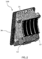
Figure 2 shows another perspective view of a heat exchange system in accordance with the present invention for a lighting device showing the heat exchange airfoils and plenum arrangement. -
Figure 3 shows a side view of the heat exchange system for a lighting device indicating an air channel and air flow direction, according to an embodiment of the present invention. -
Figure 4 shows a perspective view of another embodiment of heat exchange system for a lighting device, according to an embodiment of the present invention. -
Figure 5 shows a top view of the heat exchange system shown inFigure 4 , according to an embodiment of the present invention. -
Figure 6 shows a side view of the heat exchange system shown inFigure 4 for a lighting device indicating an air channel and air flow direction, according to an embodiment of the present invention. - Hereinafter, embodiments of the present invention will be described with reference to the accompanying drawings.
-
Figure 1 shows a perspective view of a heat exchange system of a lighting device, according to an embodiment of the present invention. -
Figure 1a shows an exploded view of a heat exchange system (100) showing the air channel (20) and a plenum (12). -
Figure 2 shows the heat exchange system (100) according to an embodiment of the present invention comprising a heat transfer airfoils (10), plenum (12) attached to the heat transfer airfoils (10) and a blower module (14). The plenum (12) according to the embodiment is attached to the heat transfer airfoils (10) of the heat exchange system by means of suitable bonding means such as adhesive bonding, heat friction spot joining, welding or any other suitable means. The plenum (12) is made of a synthetic polymer or the like. The plenum (12) arrangement on the heat transfer airfoils (10) creates an air channel (20) (shown inFigure 3 ). The air channel (20) passes through the heat transfer airfoils (10) of the heat exchange system; the air channel (20) further has a curvilinear profile. In a preferred embodiment, the outer curve of the air channel (20) is tangential with the hot heat zone (30) of the heat transfer system (100). The air channel (20) has a variable cross sectional area with reducing ration of 0.3 to 0.7 at the outlet portion of the air channel (20) as compared to the inlet portion of the air channel (20). The blower module (14) is assembled at the inlet portion of the air channel (20). -
Figure 3 shows the side view of the heat exchange system (100) according to the embodiment of the present invention. The figure shows the blower module (14) assembled in relation to the air channel (20). The blower module (14) is assembled such that maximum air is directed to the high heat regions (30) of the heat exchange system (100). According to the invention, the axis (A) of the blower module (14) is inclined towards the heat zone (30) of the heat exchange system (100). The high heat region (30) is formed on the base plate (16) directly behind the light source (32). The light source (32) and the high heat region (30) here are depicted for clarity and reference purpose and should not be taken as restricting the scope of the invention. In a preferred embodiment, the light source (32) is a monolithic LED. The blower module (14) blows the air through the air channel (20) and due to the profile of the air channel (20) and the arrangement of the blower module (14) maximum air is directed on the heat zone at high velocity. The high velocity air passing over the heat zone takes away the heat away from the heat region and out of the heat exchange system through the outlet. Additionally, the heat transfer airfoils (10) which extend outwards from the base plate (16) also carry heat away from the high heat region through conduction. The air channel (20) by design as per the present invention passing through the heat transfer airfoils (10) directs air over the heat transfer airfoils. Due to the passing of the high velocity air over the heat transfer airfoils (10) heat is transferred by means of forced convection. The curvilinear profile and section reduction of the air channel (20) ensures high velocity air across the air channel with minimum turbulence created in the system. -
Figure 4 shows another embodiment of heat exchange system for a lighting device, of the present invention. The figure shows the plenum (12) attached to the heat transfer airfoils (10). Additionally, the figure shows secondary heat transfer airfoils (18) extending out of the plenum (12). The secondary heat transfer airfoils (18) aid in further heat transfer by means of natural convection. The arrangement increases the heat transfer rate giving more efficiency to the system. -
Figure 5 shows the top view of the heat exchange system (100) offigure 4 , according to the embodiment of the present invention. The figure depicts the air channel (20) passing through the heat transfer airfoils (10). The secondary heat transfer airfoils (18) are also shown in the figure. -
Figure 6 shows the air flow direction for heat transfer as per the present invention. The embodiment as shown infigure 6 works similar to the way the embodiment ofFigure 3 works. Additionally, the current embodiment has secondary heat transfer airfoils (18) extending outwards of the plenum (12). These secondary heat transfer airfoils (18) increase the rate of heat transfer. - The present invention can be adapted and modified to perform heat transfer in electronic system. In one embodiment the blower module (14) can be mounted on the outlet of the air channel (20). The blower accordingly can be modified to perform suction of air for heat transfer of the system. The system though effective will have lesser efficiency than the one with blower at inlet of air channel. In yet another embodiment of the present invention, the profile or the air channel can be adapted to form different profiles without deviating from the scope of present invention.
Claims (12)
- A lighting device for an automobile comprising:a light source (32) for producing a light beam; anda heat exchange system (100) for transferring heat away from the light source, the heat exchange system (100) comprising:a plurality of heat transfer airfoils (10);an air channel (20) passing through the plurality of heat transfer airfoils (10) having at least one air inlet portion and at least one air outlet portion, the air channel (20) comprises a plenum (12) forming the outer portion of the air channel (20); anda blower module (14) arranged on the at least one air inlet portion of the air channel, wherein the axis (A) of the blower module (14) is inclined towards the heat zone (30) of the heat exchange system (100).
- A lighting device as claimed in claim 1, wherein the heat exchange system (100) is assembled on the rear side of the light source (32) using base plate (16).
- A lighting device as claimed in claim 1, wherein heat transfer airfoils (10) extend outwards and away from the base plate (16).
- A lighting device as claimed in claim 1, wherein the air channel (20) characterizes variable cross sectional area at the at least one air inlet portion and at the at least one air outlet portion.
- A lighting system as claimed in claim 4, wherein the variable cross sectional area of the air channel (20) ranges from a ratio of 1:0.7 to 1:0.3 across the at least one air inlet portion and the at least one air outlet portion.
- A lighting device as claimed in claim 4, wherein the air channel (20) has a curvilinear profile from the at least one air inlet portion towards the at least one air outlet portion.
- A lighting device as claimed in claim 6, wherein the outer curve of the air channel (20) is tangential with the heat zone (30) of the heat transfer system (100).
- A lighting device as claimed in any of the preceding claims, wherein the air channel (20) and the blower module (14) are arranged to ensure maximum air flow on the heat zone (30) of the heat exchange system (100).
- A lighting device as claimed in claim 1, wherein the plenum (12) is made of a synthetic polymer or the like.
- A lighting device as claimed in claim 1, wherein the plenum (12) is attached to the plurality of heat transfer airfoils (10) by bonding means.
- A lighting device as claimed in claim 10, wherein the bonding means for attaching the plenum (12) on to the plurality of heat transfer airfoils (10) is adhesive bonding, friction spot joining, or welding.
- A lighting device as claimed in claim 1, wherein the light source (32) is a monolithic LED.
Priority Applications (2)
| Application Number | Priority Date | Filing Date | Title |
|---|---|---|---|
| EP18214707.4A EP3671023A1 (en) | 2018-12-20 | 2018-12-20 | Heat exchanger for electronic components |
| PCT/EP2019/085471 WO2020127134A1 (en) | 2018-12-20 | 2019-12-17 | Heat exchanger for electronic components |
Applications Claiming Priority (1)
| Application Number | Priority Date | Filing Date | Title |
|---|---|---|---|
| EP18214707.4A EP3671023A1 (en) | 2018-12-20 | 2018-12-20 | Heat exchanger for electronic components |
Publications (1)
| Publication Number | Publication Date |
|---|---|
| EP3671023A1 true EP3671023A1 (en) | 2020-06-24 |
Family
ID=64870344
Family Applications (1)
| Application Number | Title | Priority Date | Filing Date |
|---|---|---|---|
| EP18214707.4A Pending EP3671023A1 (en) | 2018-12-20 | 2018-12-20 | Heat exchanger for electronic components |
Country Status (2)
| Country | Link |
|---|---|
| EP (1) | EP3671023A1 (en) |
| WO (1) | WO2020127134A1 (en) |
Cited By (1)
| Publication number | Priority date | Publication date | Assignee | Title |
|---|---|---|---|---|
| EP4656936A1 (en) * | 2024-05-29 | 2025-12-03 | ZKW Group GmbH | Vehicle lamp, in particular motor vehicle headlamp |
Citations (4)
| Publication number | Priority date | Publication date | Assignee | Title |
|---|---|---|---|---|
| DE102007043961A1 (en) * | 2007-09-14 | 2009-03-19 | Automotive Lighting Reutlingen Gmbh | Illuminating device, has closed air passage provided with essentially horizontal extension, and conveying unit actively conveying air through air passage, and heat sink partially arranged in air stream that flows through air passage |
| DE102010002664A1 (en) * | 2010-03-08 | 2011-09-08 | Osram Gesellschaft mit beschränkter Haftung | Light emitting diode lamp, particularly light emitting diode vehicle headlamp, comprises light emitting disk, and heat sink for light emitting diode, where airflow with waste heat from heat sink is directed directly on light emitting disk |
| EP3043107A1 (en) * | 2015-01-09 | 2016-07-13 | Valeo Vision | Optical module for motor vehicle headlight |
| EP3147556A1 (en) * | 2015-09-24 | 2017-03-29 | Stanley Electric Co., Ltd. | Vehicle lighting apparatus |
-
2018
- 2018-12-20 EP EP18214707.4A patent/EP3671023A1/en active Pending
-
2019
- 2019-12-17 WO PCT/EP2019/085471 patent/WO2020127134A1/en not_active Ceased
Patent Citations (4)
| Publication number | Priority date | Publication date | Assignee | Title |
|---|---|---|---|---|
| DE102007043961A1 (en) * | 2007-09-14 | 2009-03-19 | Automotive Lighting Reutlingen Gmbh | Illuminating device, has closed air passage provided with essentially horizontal extension, and conveying unit actively conveying air through air passage, and heat sink partially arranged in air stream that flows through air passage |
| DE102010002664A1 (en) * | 2010-03-08 | 2011-09-08 | Osram Gesellschaft mit beschränkter Haftung | Light emitting diode lamp, particularly light emitting diode vehicle headlamp, comprises light emitting disk, and heat sink for light emitting diode, where airflow with waste heat from heat sink is directed directly on light emitting disk |
| EP3043107A1 (en) * | 2015-01-09 | 2016-07-13 | Valeo Vision | Optical module for motor vehicle headlight |
| EP3147556A1 (en) * | 2015-09-24 | 2017-03-29 | Stanley Electric Co., Ltd. | Vehicle lighting apparatus |
Cited By (1)
| Publication number | Priority date | Publication date | Assignee | Title |
|---|---|---|---|---|
| EP4656936A1 (en) * | 2024-05-29 | 2025-12-03 | ZKW Group GmbH | Vehicle lamp, in particular motor vehicle headlamp |
Also Published As
| Publication number | Publication date |
|---|---|
| WO2020127134A1 (en) | 2020-06-25 |
Similar Documents
| Publication | Publication Date | Title |
|---|---|---|
| US7329033B2 (en) | Convectively cooled headlamp assembly | |
| CN100389493C (en) | heat sink | |
| US10962215B2 (en) | Active radiator with omnidirectional air convection and stage lighting fixture using the same | |
| CN101641005B (en) | Radiating device | |
| US20090135620A1 (en) | Vehicle lamp | |
| CN103175179A (en) | Radiator | |
| CN116744645A (en) | Power equipment and photovoltaic systems | |
| CN112739156A (en) | Heat dissipation module, radiator and power equipment | |
| WO2020127134A1 (en) | Heat exchanger for electronic components | |
| US20190360682A1 (en) | Lighting fixture for vehicle | |
| US20100181886A1 (en) | Heat dissipating module | |
| JP5026901B2 (en) | Lamp | |
| TWI589833B (en) | Cooling device | |
| KR102003171B1 (en) | Forced Convection Heat Sink | |
| CN219328973U (en) | Heat radiation structure and projector | |
| CN217540444U (en) | Radiator and lamp comprising same | |
| US12203629B2 (en) | Automotive lighting device heat exchange system with an intermediate portion having modified air duct arrangement | |
| CN217131148U (en) | Module radiator structure capable of improving radiating efficiency | |
| CN213208032U (en) | Heat dissipation device and air conditioner | |
| JP6811600B2 (en) | Heat dissipation structure of vehicle lighting equipment | |
| CN214228719U (en) | High-efficiency heat dissipation module | |
| CN113412392B (en) | Air guides, cooling devices and lighting devices for cooling lighting devices | |
| CN210861023U (en) | LED lamp radiator | |
| CN222578022U (en) | Car light cooling system and car light | |
| CN216011397U (en) | Air-cooled heat dissipation device |
Legal Events
| Date | Code | Title | Description |
|---|---|---|---|
| PUAI | Public reference made under article 153(3) epc to a published international application that has entered the european phase |
Free format text: ORIGINAL CODE: 0009012 |
|
| STAA | Information on the status of an ep patent application or granted ep patent |
Free format text: STATUS: REQUEST FOR EXAMINATION WAS MADE |
|
| 17P | Request for examination filed |
Effective date: 20181220 |
|
| AK | Designated contracting states |
Kind code of ref document: A1 Designated state(s): AL AT BE BG CH CY CZ DE DK EE ES FI FR GB GR HR HU IE IS IT LI LT LU LV MC MK MT NL NO PL PT RO RS SE SI SK SM TR |
|
| AX | Request for extension of the european patent |
Extension state: BA ME |
|
| STAA | Information on the status of an ep patent application or granted ep patent |
Free format text: STATUS: EXAMINATION IS IN PROGRESS |
|
| 17Q | First examination report despatched |
Effective date: 20221010 |
|
| P01 | Opt-out of the competence of the unified patent court (upc) registered |
Effective date: 20230528 |