EP3671019A1 - Vehicle lighting and/or signalling device - Google Patents
Vehicle lighting and/or signalling device Download PDFInfo
- Publication number
- EP3671019A1 EP3671019A1 EP18425105.6A EP18425105A EP3671019A1 EP 3671019 A1 EP3671019 A1 EP 3671019A1 EP 18425105 A EP18425105 A EP 18425105A EP 3671019 A1 EP3671019 A1 EP 3671019A1
- Authority
- EP
- European Patent Office
- Prior art keywords
- light
- upstream
- wall
- downstream
- lighting
- Prior art date
- Legal status (The legal status is an assumption and is not a legal conclusion. Google has not performed a legal analysis and makes no representation as to the accuracy of the status listed.)
- Granted
Links
Images


Classifications
-
- F—MECHANICAL ENGINEERING; LIGHTING; HEATING; WEAPONS; BLASTING
- F21—LIGHTING
- F21S—NON-PORTABLE LIGHTING DEVICES; SYSTEMS THEREOF; VEHICLE LIGHTING DEVICES SPECIALLY ADAPTED FOR VEHICLE EXTERIORS
- F21S43/00—Signalling devices specially adapted for vehicle exteriors, e.g. brake lamps, direction indicator lights or reversing lights
- F21S43/20—Signalling devices specially adapted for vehicle exteriors, e.g. brake lamps, direction indicator lights or reversing lights characterised by refractors, transparent cover plates, light guides or filters
- F21S43/235—Light guides
- F21S43/249—Light guides with two or more light sources being coupled into the light guide
-
- B—PERFORMING OPERATIONS; TRANSPORTING
- B60—VEHICLES IN GENERAL
- B60Q—ARRANGEMENT OF SIGNALLING OR LIGHTING DEVICES, THE MOUNTING OR SUPPORTING THEREOF OR CIRCUITS THEREFOR, FOR VEHICLES IN GENERAL
- B60Q1/00—Arrangement of optical signalling or lighting devices, the mounting or supporting thereof or circuits therefor
- B60Q1/0029—Spatial arrangement
- B60Q1/0041—Spatial arrangement of several lamps in relation to each other
- B60Q1/0058—Stacked, i.e. one lamp located behind the other in the optical axis direction
-
- B—PERFORMING OPERATIONS; TRANSPORTING
- B60—VEHICLES IN GENERAL
- B60Q—ARRANGEMENT OF SIGNALLING OR LIGHTING DEVICES, THE MOUNTING OR SUPPORTING THEREOF OR CIRCUITS THEREFOR, FOR VEHICLES IN GENERAL
- B60Q3/00—Arrangement of lighting devices for vehicle interiors; Lighting devices specially adapted for vehicle interiors
- B60Q3/60—Arrangement of lighting devices for vehicle interiors; Lighting devices specially adapted for vehicle interiors characterised by optical aspects
- B60Q3/62—Arrangement of lighting devices for vehicle interiors; Lighting devices specially adapted for vehicle interiors characterised by optical aspects using light guides
- B60Q3/64—Arrangement of lighting devices for vehicle interiors; Lighting devices specially adapted for vehicle interiors characterised by optical aspects using light guides for a single lighting device
-
- F—MECHANICAL ENGINEERING; LIGHTING; HEATING; WEAPONS; BLASTING
- F21—LIGHTING
- F21S—NON-PORTABLE LIGHTING DEVICES; SYSTEMS THEREOF; VEHICLE LIGHTING DEVICES SPECIALLY ADAPTED FOR VEHICLE EXTERIORS
- F21S43/00—Signalling devices specially adapted for vehicle exteriors, e.g. brake lamps, direction indicator lights or reversing lights
- F21S43/10—Signalling devices specially adapted for vehicle exteriors, e.g. brake lamps, direction indicator lights or reversing lights characterised by the light source
- F21S43/13—Signalling devices specially adapted for vehicle exteriors, e.g. brake lamps, direction indicator lights or reversing lights characterised by the light source characterised by the type of light source
- F21S43/14—Light emitting diodes [LED]
-
- F—MECHANICAL ENGINEERING; LIGHTING; HEATING; WEAPONS; BLASTING
- F21—LIGHTING
- F21S—NON-PORTABLE LIGHTING DEVICES; SYSTEMS THEREOF; VEHICLE LIGHTING DEVICES SPECIALLY ADAPTED FOR VEHICLE EXTERIORS
- F21S43/00—Signalling devices specially adapted for vehicle exteriors, e.g. brake lamps, direction indicator lights or reversing lights
- F21S43/20—Signalling devices specially adapted for vehicle exteriors, e.g. brake lamps, direction indicator lights or reversing lights characterised by refractors, transparent cover plates, light guides or filters
- F21S43/235—Light guides
- F21S43/236—Light guides characterised by the shape of the light guide
- F21S43/239—Light guides characterised by the shape of the light guide plate-shaped
-
- F—MECHANICAL ENGINEERING; LIGHTING; HEATING; WEAPONS; BLASTING
- F21—LIGHTING
- F21S—NON-PORTABLE LIGHTING DEVICES; SYSTEMS THEREOF; VEHICLE LIGHTING DEVICES SPECIALLY ADAPTED FOR VEHICLE EXTERIORS
- F21S43/00—Signalling devices specially adapted for vehicle exteriors, e.g. brake lamps, direction indicator lights or reversing lights
- F21S43/20—Signalling devices specially adapted for vehicle exteriors, e.g. brake lamps, direction indicator lights or reversing lights characterised by refractors, transparent cover plates, light guides or filters
- F21S43/235—Light guides
- F21S43/242—Light guides characterised by the emission area
- F21S43/243—Light guides characterised by the emission area emitting light from one or more of its extremities
-
- F—MECHANICAL ENGINEERING; LIGHTING; HEATING; WEAPONS; BLASTING
- F21—LIGHTING
- F21S—NON-PORTABLE LIGHTING DEVICES; SYSTEMS THEREOF; VEHICLE LIGHTING DEVICES SPECIALLY ADAPTED FOR VEHICLE EXTERIORS
- F21S43/00—Signalling devices specially adapted for vehicle exteriors, e.g. brake lamps, direction indicator lights or reversing lights
- F21S43/30—Signalling devices specially adapted for vehicle exteriors, e.g. brake lamps, direction indicator lights or reversing lights characterised by reflectors
- F21S43/31—Optical layout thereof
- F21S43/315—Optical layout thereof using total internal reflection
Definitions
- the present invention relates to a vehicle lighting and/or signalling device.
- vehicle lighting and/or signalling device is used herein in a very broad sense so as to comprise a vehicle light, both rear and front, the latter also called a headlamp, or headlight.
- said vehicle lighting and/or signalling devices can be used both to illuminate and to send visual signals.
- the need is felt to create vehicle lights that can perform at least two of said lighting and/or signalling functions using the same portions of the emitting surface.
- the need is felt to use the same portions of the emitting surface to perform alternately, or even in unison, two distinct lighting and/or signalling functions.
- the same emitting surface may be required to realize both the side light function and the indicator light function.
- this is an example, since it is also possible to integrate the functions of brake light, rear fog light, reverse light, dipped-beam light, main-beam light and so on.
- the important thing is that there are at least two distinct light sources which when activated alternately or simultaneously can activate lighting portions at least partially overlapping each other to perform respective lighting or signalling functions.
- reference numeral 4 globally denotes a vehicle light to which the following discussion will refer, without by so doing detracting from its general application.
- the lighting and/or signalling device 4 comprises a container body or housing 8, usually of polymeric material, which generally allows the attachment of the lighting and/or signalling 4 device to the relative vehicle or to any type of support.
- the container body or housing 8 may be any shape, size and assume any position: for example, the container body 8 need not be directly associated to the body or other external fixtures of the associable vehicle.
- the container body 8 may also be associated inside the vehicle, e.g. on the instrument panel, dashboard, parcel shelf and so forth.
- the container body 8 may for example be associated, at least partially in closing, to a lenticular body 20 so as to close said containment seat 12 housing the at least one LED light source 16.
- the lenticular body 20 may be external to the vehicle lighting and or signalling device 4, so as to define at least one outer wall of the vehicle lighting and/or signalling device directly subject to the atmosphere.
- the lenticular body 20 closes the containment seat 12 and is suitable to be crossed by the beam of light produced by the light source 16 which is transmitted to the outside of the containment seat 12.
- the lenticular body 20 is arranged to cover a downstream light output wall 44 of a downstream light guide 36, as better described below.
- the lenticular body 20 is made of at least partially transparent or semi-transparent or translucent material, and may also comprise one or more opaque portions, so as to allow in any case the at least partial crossing of the light beam produced by the light source.
- the material of the lenticular body 20 is a resin such as PMMA, PC and the like.
- the lighting and/or signalling device 4 comprises, as mentioned above, an upstream light guide 24, provided with an upstream light input portion 28 (called incoupling), facing the upstream light source 16' so as to receive in input the light beam produced by the latter and to emit it in output through an upstream light output wall 32.
- an upstream light guide 24 provided with an upstream light input portion 28 (called incoupling), facing the upstream light source 16' so as to receive in input the light beam produced by the latter and to emit it in output through an upstream light output wall 32.
- the lighting and/or signalling device 4 further comprises a downstream light guide 36 provided with a downstream light input portion 40 (called incoupling), facing the downstream light source 16" so as to receive the light beam produced by the latter and emit it in output through a downstream light output wall 44.
- a downstream light guide 36 provided with a downstream light input portion 40 (called incoupling), facing the downstream light source 16" so as to receive the light beam produced by the latter and emit it in output through a downstream light output wall 44.
- the upstream light guide 24 is shaped so as to transfer, by total internal reflection, the light beam emitted by the upstream light source 16' from the upstream light output wall 32 to the intermediate wall 48 of the downstream light guide 36.
- said upstream and downstream light guides 24,36 are separated and spaced apart so that their respective upstream light output walls 32 and intermediate wall 48 are adjacent and aligned with each other.
- the upstream light guide 24 comprises at least one upstream collimation wall 60 shaped to collimate the rays produced by the upstream light source 16' and to direct them, collimated, towards the output window 56 of said upstream light output wall 32.
- said upstream collimation wall 60 is a wall having a planar or parabolic profile.
- the plane profile is a profile inclined by 45 degrees with respect to said prevailing propagation direction X-X.
- the intermediate wall 48 comprises at least one downstream collimation wall 64 shaped to collimate the rays produced by the downstream light source 16" and to collimate them towards the downstream light output wall 44.
- the intermediate wall 48 is provided with an embossed or satin-finish surface 68 so as to achieve a diffusion effect of the light rays incidental thereon.
- the upstream light guide 24, at the upstream light output wall 32 comprises at least one protrusion 72 delimited by a pair of inclined walls 76,80 and ending with said output window 56.
- two input windows 52 are provided on the intermediate wall 48 counter-shaped with respect to two corresponding output windows 56 of the upstream light output wall 32, wherein the input windows 52 and the output windows 56 are offset from each other with respect to said prevailing propagation direction X-X.
- each of the two output windows 56 of the upstream light output wall 32 is arranged on a respective protrusion 72.
- the intermediate wall 48 may comprise a plurality of input windows 52 offset from each other along the prevailing propagation direction X-X and substantially perpendicular to said prevailing propagation direction X-X.
- downstream light output wall 44 of the downstream light guide 36 is provided with optics 84 suitable to diffuse the light beam in output.
- said optics 84 may comprise a satin-finish, optical pillows and the like.
- the above description refers to upstream and downstream light guides equipped with at least one upstream light source 16' and at least one downstream light source 16".
- the light guides have a depth such as to provide a row of upstream light sources 16' and a row of downstream light sources, with respect to a transverse direction Y, perpendicular to the prevailing propagation direction X-X.
- the above description applies to all the light sources 16',16" extending along said transverse direction.
- the light sources 16', 16'' can be activated separately and/or simultaneously, depending on the lighting and/or signalling requirements.
- the upstream light sources 16 are activated, the light beam produced by these is emitted into the upstream light guide 24, through the upstream light input portion 28. Then the beam is reflected by the upstream collimation wall 60 towards the upstream light output wall 32.
- the collimated and non-collimated rays come out of upstream light guide 24 through the output windows 56; in fact, the remaining walls of the upstream light guide 24 are shaped to achieve a total internal reflection that directs the light rays towards said output windows 56.
- the collimated rays entering the input window 52 maintain their collimation inside the downstream light guide 36 thanks to the counter-shaping between the input windows 52 and the output windows 56.
- the non-collimated rays entering the downstream light guide 36 continue their non-collimated path, inside said downstream light guide 36, by total internal reflection to then come out through the downstream light output wall 44.
- the light rays are in turn diffused by the optics 84 so as to have a homogeneously illuminated emitting surface.
- the light rays emitted by the downstream light source 16" are reflected and possibly collimated by the intermediate wall 48 and/or by the downstream collimation wall 64, so as to propagate towards the downstream light output wall 44.
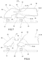
- embossed or satin-finish surface 68 serves to uniform the light beams emitted by the upstream light source 16', while it can diffuse the light beams coming from the upstream light guide 24 (embodiment in figure 8 ).
- the present invention makes it possible to overcome the drawbacks mentioned of the prior art.
- the automotive lighting and/or signalling device makes it possible to realize the dual lighting and/or signalling function using the same emitting surface portions.
- Both functions make it possible to obtain a homogeneous and uniformly lit emitting surface, avoiding any presence of luminous spots or uneven areas.
Landscapes
- Engineering & Computer Science (AREA)
- General Engineering & Computer Science (AREA)
- Mechanical Engineering (AREA)
- Physics & Mathematics (AREA)
- Microelectronics & Electronic Packaging (AREA)
- Optics & Photonics (AREA)
- Non-Portable Lighting Devices Or Systems Thereof (AREA)
- Lighting Device Outwards From Vehicle And Optical Signal (AREA)
Abstract
Description
- The present invention relates to a vehicle lighting and/or signalling device.
- The term vehicle lighting and/or signalling device is used herein in a very broad sense so as to comprise a vehicle light, both rear and front, the latter also called a headlamp, or headlight.
- This therefore comprises a sidelight, an indicator light, a brake light, a rear fog light, a reverse light, a dipped beam headlight, a main beam headlight and the like.
- In addition, the term is also intended to mean a courtesy light, dashboard or part of it; therefore, the vehicle lighting and/or signalling device may be placed both internally and externally to the vehicle.
- As is known, said vehicle lighting and/or signalling devices can be used both to illuminate and to send visual signals.
- For these purposes, said devices comprise a plurality of lighting portions having different colours and different levels of luminance (also according to the regulations to be complied with) and the like.
- In particular, the need is felt to create vehicle lights that can perform at least two of said lighting and/or signalling functions using the same portions of the emitting surface. In other words, due to space and/or aesthetic requirements, the need is felt to use the same portions of the emitting surface to perform alternately, or even in unison, two distinct lighting and/or signalling functions.
- For example, the same emitting surface may be required to realize both the side light function and the indicator light function. Obviously, this is an example, since it is also possible to integrate the functions of brake light, rear fog light, reverse light, dipped-beam light, main-beam light and so on. The important thing is that there are at least two distinct light sources which when activated alternately or simultaneously can activate lighting portions at least partially overlapping each other to perform respective lighting or signalling functions.
- There are some solutions in the art that use the same light guide equipped with LED light sources controlled independently of each other and shaped, together with the respective input and light guide surfaces, to generate light beams at lighting portions which are at least partially overlapping. These known solutions, however, have the drawback of not allowing the emission of homogeneous and clearly distinguishable light portions, since the shape of the respective light guides determines a significant dispersion of light beams with consequently less homogeneous lighting portions being obtained.
- The need is therefore felt in the art to provide a vehicle lighting and/or signalling device that allows the aforementioned technical effects to be obtained, i.e. lighting portions at least partially overlapping each other to be obtained, while ensuring a high homogeneity of lighting.
- Such need is satisfied by a vehicle lighting and/or signalling device according to claim 1.
- Other embodiments of the present invention are described in the dependent claims.
- Further characteristics and advantages of the present invention will be more clearly comprehensible from the description given below of its preferred and non-limiting embodiments, wherein:
-
figure 1 shows a perspective view, in separate parts, of a lighting and/or signalling device according to one embodiment of the present invention; -
figure 2 shows a cross-section view, in an assembled configuration, of the lighting and/or signalling device infigure 1 ; -
figure 3 shows two perspective views, in an assembled configuration, respectively total and in cross-section, of the lighting and/or signalling device infigure 1 ; - -
figures 4-6 show perspective views, from different angles, of some components of the lighting and/or signalling device infigure 1 ; -
figure 7 shows a partial cross-section view of a lighting and/or signalling device according to a further embodiment of the present invention; -
figure 8 shows a partial cross-section view of a lighting and/or signalling device according to a further embodiment of the present invention. - The elements or parts of elements common to the embodiments described below will be indicated using the same reference numerals.
- With reference to the aforementioned figures,
reference numeral 4 globally denotes a vehicle light to which the following discussion will refer, without by so doing detracting from its general application. - As mentioned above, the term lighting and/or signalling device is understood to mean indifferently a rear vehicle light or a front vehicle light, the latter also known as a headlight or headlamp, comprising an outside light of the vehicle having a lighting and/or signalling function, such as for example a side light, which may be a front, back, side position light, a direction indicator light, a brake light, a rear fog light, a reversing light, a low beam headlight, a high beam headlight, and the like.
- In addition, the term lighting and/or signalling device also means an interior courtesy light, a dashboard or part of it, a display and so forth.
- Consequently, as better described below, in its signalling function the device may comprise the possibility of sending luminous signals, logos, but also written and luminous messages of any kind.
- The lighting and/or
signalling device 4 comprises a container body orhousing 8, usually of polymeric material, which generally allows the attachment of the lighting and/or signalling 4 device to the relative vehicle or to any type of support. - For the purposes of the present invention, the container body or
housing 8 may be any shape, size and assume any position: for example, thecontainer body 8 need not be directly associated to the body or other external fixtures of the associable vehicle. - As seen, the
container body 8 may also be associated inside the vehicle, e.g. on the instrument panel, dashboard, parcel shelf and so forth. - The
container body 8 delimits acontainment seat 12 that houses a plurality of components of said lighting and/or signalling device and in particularLED light sources 16. - Preferably, said
light sources 16 are LED light sources. - The
container body 8 may for example be associated, at least partially in closing, to alenticular body 20 so as to close saidcontainment seat 12 housing the at least oneLED light source 16. - For the purposes of the present invention the
lenticular body 20 may be external to the vehicle lighting and orsignalling device 4, so as to define at least one outer wall of the vehicle lighting and/or signalling device directly subject to the atmosphere. - The
lenticular body 20 closes thecontainment seat 12 and is suitable to be crossed by the beam of light produced by thelight source 16 which is transmitted to the outside of thecontainment seat 12. In particular, thelenticular body 20 is arranged to cover a downstreamlight output wall 44 of adownstream light guide 36, as better described below. - To such purpose, the
lenticular body 20 is made of at least partially transparent or semi-transparent or translucent material, and may also comprise one or more opaque portions, so as to allow in any case the at least partial crossing of the light beam produced by the light source. - According to possible embodiments, the material of the
lenticular body 20 is a resin such as PMMA, PC and the like. - The lighting and/or signalling device of the present invention comprises at least two separately powered and activated
light sources 16',16" comprising an upstream light source 16' and adownstream light source 16" relative to a prevailing propagation direction X-X of respective emitted light beams. - It should be noted that the prevailing propagation direction X-X does not necessarily have to be understood as the emission direction of the light beam leaving the light source, but as the overall propagation direction of the light beam introduced and transmitted inside the subsequent light guide, as described below. Therefore, the concept of upstream and downstream must be understood with respect to this prevailing propagation direction X-X; consequently, the upstream light source 16' is the one that generates a light beam that is located overall upstream of the beam generated by the downstream light source 16''.
- The lighting and/or
signalling device 4 comprises, as mentioned above, anupstream light guide 24, provided with an upstream light input portion 28 (called incoupling), facing the upstream light source 16' so as to receive in input the light beam produced by the latter and to emit it in output through an upstreamlight output wall 32. - In particular, the light beam emitted by the upstream light source 16' penetrates the
upstream light guide 24, through the upstreamlight input portion 28, and, by total internal reflection, is reflected until it reaches the upstreamlight output wall 32 from which it exits, as better described below. - The lighting and/or
signalling device 4 further comprises adownstream light guide 36 provided with a downstream light input portion 40 (called incoupling), facing thedownstream light source 16" so as to receive the light beam produced by the latter and emit it in output through a downstreamlight output wall 44. - Said
light guides light output wall 32 is channelled through anintermediate wall 48 of thedownstream light guide 36 and by this reflected and transmitted through the downstreamlight output wall 44. - Advantageously, the
upstream light guide 24 is shaped so as to transfer, by total internal reflection, the light beam emitted by the upstream light source 16' from the upstreamlight output wall 32 to theintermediate wall 48 of thedownstream light guide 36. - Furthermore, the
intermediate wall 48 comprises at least oneinput window 52 counter-shaped relative to acorresponding output window 56 of the upstreamlight output wall 32. - The term counter-shaped means that the two
input 52 andoutput 56 windows have substantially the same geometry, i.e. they are offset from each other. In this way, if a collimated light beam crosses in output theupstream output window 56, the same beam, entering through thedownstream input window 52 will maintain the same collimation inside thedownstream light guide 36. Obviously, what is described does not apply to any non-collimated light rays entering through the double passage consisting of theoutput window 56 and theinput window 52. If there is no collimation upstream, the light beam entering theinput window 52 may propagate inside thedownstream light guide 36 according to the normal total internal reflection (TIR) without being collimated. - According to one embodiment, said
input window 52, and thus also itscounter-shaped output window 56, is substantially perpendicular to the prevailing propagation direction X-X. - Preferably, said upstream and
downstream light guides light output walls 32 andintermediate wall 48 are adjacent and aligned with each other. - Preferably, the
upstream light guide 24 comprises at least oneupstream collimation wall 60 shaped to collimate the rays produced by the upstream light source 16' and to direct them, collimated, towards theoutput window 56 of said upstreamlight output wall 32. - According to possible embodiments, said
upstream collimation wall 60 is a wall having a planar or parabolic profile. Typically for polymeric materials used in the vehicle lights the plane profile is a profile inclined by 45 degrees with respect to said prevailing propagation direction X-X. - According to one embodiment, the
intermediate wall 48 comprises at least onedownstream collimation wall 64 shaped to collimate the rays produced by thedownstream light source 16" and to collimate them towards the downstreamlight output wall 44. - According to a possible embodiment, the
intermediate wall 48 is provided with an embossed or satin-finish surface 68 so as to achieve a diffusion effect of the light rays incidental thereon. - Preferably, said embossed or satin-finish surface 68 involves said at least one
input window 52 of theintermediate wall 48. The purpose of said embossed or satin-finish surface 68 is to diffuse the light beams incident thereon, coming from the upstreamlight output wall 32 and appropriately diffuse them inside the downstreamlight guide 36. - According to one embodiment, the upstream
light guide 24, at the upstreamlight output wall 32, comprises at least oneprotrusion 72 delimited by a pair ofinclined walls output window 56. - In particular, said
inclined walls output window 56. Such light beams involving theinclined walls light input portion 28 and by theupstream collimation wall 60 and enter the downstreamlight guide 36 through theinput windows 52 inclined with respect to the prevailing propagation direction X-X. However, such light beams are transmitted in output by the downstreamlight output wall 44 maintaining the total internal reflection condition (TIR) inside the downstreamlight guide 36. - According to a preferred embodiment, two
input windows 52 are provided on theintermediate wall 48 counter-shaped with respect to twocorresponding output windows 56 of the upstreamlight output wall 32, wherein theinput windows 52 and theoutput windows 56 are offset from each other with respect to said prevailing propagation direction X-X. - Preferably, each of the two
output windows 56 of the upstreamlight output wall 32 is arranged on arespective protrusion 72. - In general, the
intermediate wall 48 may comprise a plurality ofinput windows 52 offset from each other along the prevailing propagation direction X-X and substantially perpendicular to said prevailing propagation direction X-X. -
Said input windows 52 are interspersed between portions ofintermediate wall 48 parallel to each other, so as to homogeneously reflect the light beams produced by the downstreamlight source 16". Preferably, saidintermediate wall portions 48 aredownstream collimation walls 64 so as not only to reflect but also to collimate the light beam produced by the downstream light source 16''. - Preferably, the downstream
light output wall 44 of the downstreamlight guide 36 is provided with optics 84 suitable to diffuse the light beam in output. - For example, said optics 84 may comprise a satin-finish, optical pillows and the like.
- Finally, it should be noted that the above description refers to upstream and downstream light guides equipped with at least one upstream light source 16' and at least one downstream
light source 16". In fact, very often the light guides have a depth such as to provide a row of upstream light sources 16' and a row of downstream light sources, with respect to a transverse direction Y, perpendicular to the prevailing propagation direction X-X. Obviously, the above description applies to all thelight sources 16',16" extending along said transverse direction. - The functioning of a vehicle lighting and/or signalling device according to the present invention will now be described.
- In particular, as seen, the light sources 16', 16'' can be activated separately and/or simultaneously, depending on the lighting and/or signalling requirements.
- If the upstream
light sources 16 are activated, the light beam produced by these is emitted into the upstreamlight guide 24, through the upstreamlight input portion 28. Then the beam is reflected by theupstream collimation wall 60 towards the upstreamlight output wall 32. - The collimated and non-collimated rays come out of upstream
light guide 24 through theoutput windows 56; in fact, the remaining walls of the upstreamlight guide 24 are shaped to achieve a total internal reflection that directs the light rays towards saidoutput windows 56. - The collimated rays entering the
input window 52 maintain their collimation inside the downstreamlight guide 36 thanks to the counter-shaping between theinput windows 52 and theoutput windows 56. The non-collimated rays entering the downstreamlight guide 36 continue their non-collimated path, inside said downstreamlight guide 36, by total internal reflection to then come out through the downstreamlight output wall 44. - On the downstream
light output wall 44 the light rays are in turn diffused by the optics 84 so as to have a homogeneously illuminated emitting surface. - Furthermore, the light rays emitted by the downstream
light source 16" are reflected and possibly collimated by theintermediate wall 48 and/or by thedownstream collimation wall 64, so as to propagate towards the downstreamlight output wall 44. - It should be noted that the presence of the embossed or satin-finish surface 68 serves to uniform the light beams emitted by the upstream light source 16', while it can diffuse the light beams coming from the upstream light guide 24 (embodiment in
figure 8 ). - As may be appreciated from the description, the present invention makes it possible to overcome the drawbacks mentioned of the prior art.
- In particular, the automotive lighting and/or signalling device according to the present invention makes it possible to realize the dual lighting and/or signalling function using the same emitting surface portions.
- Both functions make it possible to obtain a homogeneous and uniformly lit emitting surface, avoiding any presence of luminous spots or uneven areas.
- Obviously, the lighting functions can be obtained through the same emitting surface that receives the light beams coming from the downstream light output wall. This reduces the overall dimensions of the lighting and/or signalling device.
- A person skilled in the art may make numerous modifications and variations to the lighting and/or signalling devices described above so as to satisfy contingent and specific requirements while remaining within the sphere of protection of the invention as defined by the following claims.
Claims (16)
- Lighting and/or signalling device (4), in particular for the automotive sector, comprising:at least two separately powered and activated light sources (16',16" comprising an upstream light source (16') and a downstream light source (16") relative to a prevailing propagation direction (X-X) of respective emitted light beams,- an upstream light guide (24), provided with an upstream light input portion (28), facing the upstream light source (16') so as to receive in input the light beam produced by the latter and to emit it in output through an upstream light output wall (32),- a downstream light guide (36) provided with a downstream light input portion (40), facing the downstream light source (16") so as to receive the light beam produced by the latter and emit it in output through a downstream light output wall (44),- said upstream and downstream light guides (24,36) being arranged side by side in series with each other with respect to said prevailing propagation direction(X-X), so that the light beam emitted by the upstream light output wall (32) is channelled through an intermediate wall (48) of the downstream light guide (36) and by this is reflected and transmitted through the downstream light output wall (44),characterised in thatthe upstream light guide (24) is shaped so as to transfer, by total internal reflection, the light beam emitted by the upstream light source (16') from the upstream light output wall (32) to the intermediate wall (48) of the downstream light guide (36),- wherein the intermediate wall (48) comprises at least one input window (52) counter-shaped relative to a corresponding output window (56) of the upstream light output wall (32).
- The lighting and/or signalling device (4) according to claim 1, wherein the upstream light guide (24) comprises at least one upstream collimation wall (60) shaped to collimate the rays produced by the upstream light source (16') and to direct them, collimated, towards the output window (56) of said upstream light output wall (32).
- The lighting and/or signalling device (4) according to claim 2, wherein said upstream collimation wall (60) is a wall having a planar or parabolic profile.
- The lighting and/or signalling device (4) according to claim 1, 2 or 3 wherein the intermediate wall (48) comprises at least one downstream collimation wall (64) shaped to collimate the rays produced by the downstream light source (16') and to collimate them towards the downstream light output wall (44).
- The lighting and/or signalling device (4) according to any of the claims from 1 to 4, wherein the intermediate wall (48) is provided with an embossed or satin-finish surface (68) so as to achieve a diffusion effect of the light rays incidental thereon.
- The lighting and/or signalling device (4) according to claim 5, wherein said embossed or satin-finish surface (68) involves said at least one input window (52) of the intermediate wall (48).
- The lighting and/or signalling device (4) according to any of the claims from 1 to 6, wherein the upstream light guide (24), at the upstream light output wall (32), comprises at least one protrusion (72) delimited by a pair of inclined walls (76,80) and ending with said output window (56), said inclined walls (76,80) being shaped to reflect the light beams produced by the upstream light source (16'), by total internal reflection, and to channel them all towards said output window (56).
- The lighting and/or signalling device (4) according to any of the claims from 1 to 7, wherein said input window (52) is substantially perpendicular to the prevailing propagation direction (X-X).
- The lighting and/or signalling device (4) according to any of the claims from 1 to 8, wherein said upstream and downstream light guides (24,36) are separated and spaced apart so that their respective upstream light output walls (32) and intermediate wall (48) are adjacent and aligned with each other.
- The lighting and/or signalling device (4) according to any of the claims from 1 to 9, wherein two input windows (52 are provided on the intermediate wall (48 counter-shaped with respect to two corresponding output windows (56) of the upstream light output wall (32), wherein the input windows (52) and the output windows (56) are offset from each other with respect to said prevailing propagation direction (X-X.).
- The lighting and/or signalling device (4) according to claim 10, wherein the intermediate wall (48) comprises a plurality of input windows (52) offset from each other along the prevailing propagation direction (X-X) and substantially perpendicular to said prevailing propagation direction (X-X).
- The lighting and/or signalling device (4) according to claim 11, wherein said input windows (52) are interspersed between portions of intermediate wall (48) parallel to each other, so as to homogeneously reflect the light beams produced by the downstream light source (16").
- The lighting and/or signalling device (4) according to any of the claims from 1 to 12, wherein the downstream light output wall (44) of the downstream light guide (36) is provided with optics (84) suitable to diffuse the light beam in output.
- The lighting and/or signalling device (4) according to claim 13, wherein said optics (84) comprise a satin-finish, optical pillows and the like.
- The lighting and/or signalling device (4) according to any of the claims from 1 to 14, wherein the lighting device (4) comprises a container body (8) delimiting a containment seat (12) housing said upstream and downstream light guides (24,36) with their respective light sources (16), said containment seat (12) being closed by a lenticular body (20) arranged to cover the downstream light output wall (44) of the downstream light guide (36).
- The lighting and/or signalling device (4) according to any of the preceding claims, wherein said light sources (16) are LED light sources.
Priority Applications (3)
| Application Number | Priority Date | Filing Date | Title |
|---|---|---|---|
| PL18425105.6T PL3671019T3 (en) | 2018-12-21 | 2018-12-21 | Vehicle lighting and/or signalling device |
| EP18425105.6A EP3671019B1 (en) | 2018-12-21 | 2018-12-21 | Vehicle lighting and/or signalling device |
| ES18425105T ES2931226T3 (en) | 2018-12-21 | 2018-12-21 | Vehicle lighting and/or signaling device |
Applications Claiming Priority (1)
| Application Number | Priority Date | Filing Date | Title |
|---|---|---|---|
| EP18425105.6A EP3671019B1 (en) | 2018-12-21 | 2018-12-21 | Vehicle lighting and/or signalling device |
Publications (2)
| Publication Number | Publication Date |
|---|---|
| EP3671019A1 true EP3671019A1 (en) | 2020-06-24 |
| EP3671019B1 EP3671019B1 (en) | 2022-08-31 |
Family
ID=65443611
Family Applications (1)
| Application Number | Title | Priority Date | Filing Date |
|---|---|---|---|
| EP18425105.6A Active EP3671019B1 (en) | 2018-12-21 | 2018-12-21 | Vehicle lighting and/or signalling device |
Country Status (3)
| Country | Link |
|---|---|
| EP (1) | EP3671019B1 (en) |
| ES (1) | ES2931226T3 (en) |
| PL (1) | PL3671019T3 (en) |
Cited By (7)
| Publication number | Priority date | Publication date | Assignee | Title |
|---|---|---|---|---|
| DE102021100905A1 (en) | 2020-09-17 | 2022-03-17 | Zhejiang Jinye Auto Parts Co., Ltd. | Method for displaying multiple signal functions of a signal lamp and signal lamp with multiple signal functions |
| US20220307670A1 (en) * | 2019-08-28 | 2022-09-29 | Valeo Vision | Light-guiding assembly, vehicle lamp, and vehicle |
| FR3122131A1 (en) * | 2021-04-26 | 2022-10-28 | Psa Automobiles Sa | Illumination module for optical unit for lighting and/or motor vehicle signaling |
| CN115407479A (en) * | 2022-09-05 | 2022-11-29 | 中国科学院长春光学精密机械与物理研究所 | A method and system for automatic high-precision focusing of the main optical path of a telescope |
| WO2023072533A1 (en) * | 2021-10-26 | 2023-05-04 | HELLA GmbH & Co. KGaA | Headlight for a motor vehicle, and adaptive beam module for a headlight of this kind |
| US20240310019A1 (en) * | 2023-03-16 | 2024-09-19 | Stanley Electric Co., Ltd. | Lighting tool for vehicle |
| DE102023109202A1 (en) * | 2023-04-12 | 2024-10-17 | Marelli Automotive Lighting Reutlingen (Germany) GmbH | Illumination device with a volume-scattering TIR optics |
Citations (8)
| Publication number | Priority date | Publication date | Assignee | Title |
|---|---|---|---|---|
| FR2804493A1 (en) * | 2000-01-31 | 2001-08-03 | Renault | MOTOR VEHICLE SIGNALING LIGHT PROJECTOR WITH LIGHT GUIDES |
| EP2889529A2 (en) * | 2013-12-27 | 2015-07-01 | Automotive Lighting Reutlingen GmbH | Motor vehicle light with a linear or flat appearance |
| DE102014110347A1 (en) * | 2014-07-23 | 2016-01-28 | Dr. Ing. H.C. F. Porsche Aktiengesellschaft | light guide |
| DE102015204747A1 (en) * | 2015-03-17 | 2016-09-22 | Volkswagen Aktiengesellschaft | Lighting device for a motor vehicle |
| JP2017010840A (en) * | 2015-06-24 | 2017-01-12 | 株式会社小糸製作所 | Vehicle lamp |
| FR3042751A1 (en) * | 2015-10-23 | 2017-04-28 | Automotive Lighting Rear Lamps France | COMPACT LIGHTING AND / OR SIGNALING DEVICE FOR VEHICLE |
| WO2017168387A1 (en) * | 2016-03-31 | 2017-10-05 | Automotive Lighting Italia S.P.A. | Automotive lighting unit with a light guide plate |
| DE102017119500A1 (en) * | 2017-08-25 | 2019-02-28 | Dr. Ing. H.C. F. Porsche Aktiengesellschaft | lighting device |
-
2018
- 2018-12-21 EP EP18425105.6A patent/EP3671019B1/en active Active
- 2018-12-21 ES ES18425105T patent/ES2931226T3/en active Active
- 2018-12-21 PL PL18425105.6T patent/PL3671019T3/en unknown
Patent Citations (8)
| Publication number | Priority date | Publication date | Assignee | Title |
|---|---|---|---|---|
| FR2804493A1 (en) * | 2000-01-31 | 2001-08-03 | Renault | MOTOR VEHICLE SIGNALING LIGHT PROJECTOR WITH LIGHT GUIDES |
| EP2889529A2 (en) * | 2013-12-27 | 2015-07-01 | Automotive Lighting Reutlingen GmbH | Motor vehicle light with a linear or flat appearance |
| DE102014110347A1 (en) * | 2014-07-23 | 2016-01-28 | Dr. Ing. H.C. F. Porsche Aktiengesellschaft | light guide |
| DE102015204747A1 (en) * | 2015-03-17 | 2016-09-22 | Volkswagen Aktiengesellschaft | Lighting device for a motor vehicle |
| JP2017010840A (en) * | 2015-06-24 | 2017-01-12 | 株式会社小糸製作所 | Vehicle lamp |
| FR3042751A1 (en) * | 2015-10-23 | 2017-04-28 | Automotive Lighting Rear Lamps France | COMPACT LIGHTING AND / OR SIGNALING DEVICE FOR VEHICLE |
| WO2017168387A1 (en) * | 2016-03-31 | 2017-10-05 | Automotive Lighting Italia S.P.A. | Automotive lighting unit with a light guide plate |
| DE102017119500A1 (en) * | 2017-08-25 | 2019-02-28 | Dr. Ing. H.C. F. Porsche Aktiengesellschaft | lighting device |
Cited By (9)
| Publication number | Priority date | Publication date | Assignee | Title |
|---|---|---|---|---|
| US20220307670A1 (en) * | 2019-08-28 | 2022-09-29 | Valeo Vision | Light-guiding assembly, vehicle lamp, and vehicle |
| DE102021100905A1 (en) | 2020-09-17 | 2022-03-17 | Zhejiang Jinye Auto Parts Co., Ltd. | Method for displaying multiple signal functions of a signal lamp and signal lamp with multiple signal functions |
| FR3122131A1 (en) * | 2021-04-26 | 2022-10-28 | Psa Automobiles Sa | Illumination module for optical unit for lighting and/or motor vehicle signaling |
| WO2023072533A1 (en) * | 2021-10-26 | 2023-05-04 | HELLA GmbH & Co. KGaA | Headlight for a motor vehicle, and adaptive beam module for a headlight of this kind |
| US12429185B2 (en) | 2021-10-26 | 2025-09-30 | HELLA GmbH & Co. KGaA | Headlamp for a motor vehicle and appearance light module for such a headlamp |
| CN115407479A (en) * | 2022-09-05 | 2022-11-29 | 中国科学院长春光学精密机械与物理研究所 | A method and system for automatic high-precision focusing of the main optical path of a telescope |
| US20240310019A1 (en) * | 2023-03-16 | 2024-09-19 | Stanley Electric Co., Ltd. | Lighting tool for vehicle |
| US12215838B2 (en) * | 2023-03-16 | 2025-02-04 | Stanley Electric Co., Ltd. | Lighting tool for vehicle |
| DE102023109202A1 (en) * | 2023-04-12 | 2024-10-17 | Marelli Automotive Lighting Reutlingen (Germany) GmbH | Illumination device with a volume-scattering TIR optics |
Also Published As
| Publication number | Publication date |
|---|---|
| EP3671019B1 (en) | 2022-08-31 |
| ES2931226T3 (en) | 2022-12-27 |
| PL3671019T3 (en) | 2023-01-02 |
Similar Documents
| Publication | Publication Date | Title |
|---|---|---|
| EP3671019B1 (en) | Vehicle lighting and/or signalling device | |
| US8480266B2 (en) | Vehicle light unit and vehicle light | |
| KR101957390B1 (en) | Overhead console and vehicle-body upper structure | |
| JP6194040B2 (en) | Vehicle lighting | |
| KR101748536B1 (en) | Vehicle light for lighting the interior of a vehicle | |
| US11499690B2 (en) | Automotive lighting and/or signaling device | |
| JP6264789B2 (en) | Vehicle lighting | |
| JP2016095996A (en) | Composite lamp for vehicles | |
| US10655811B2 (en) | Vehicle light with portions at different luminance levels | |
| KR102541150B1 (en) | Vehicle light comprising a portion of light emission with opalescent effect | |
| US20180149330A1 (en) | Light device, especially a signal lamp, for motor vehicles | |
| CZ2016481A3 (en) | A lighting device for motor vehicles | |
| JP2008258037A (en) | Vehicle headlamp | |
| JP2015222618A (en) | Vehicle light guide member, vehicle lamp | |
| JP6039333B2 (en) | Vehicle lighting | |
| JP2016197575A (en) | Vehicle light guide, vehicle lamp | |
| WO2014141597A1 (en) | Vehicle lamp fitting | |
| JP6511960B2 (en) | Vehicle lamp | |
| EP3839330B1 (en) | Automotive lighting and/or signaling device | |
| WO2016027511A1 (en) | Passenger compartment illumination device | |
| JP2008103273A (en) | Vehicle lighting | |
| US10837618B2 (en) | Vehicular lamp | |
| WO2016158355A1 (en) | Vehicular interior member with illumination device | |
| JP2019085091A (en) | Vehicle lighting system | |
| EP3825602B1 (en) | Automotive lighting and/or signaling device |
Legal Events
| Date | Code | Title | Description |
|---|---|---|---|
| PUAI | Public reference made under article 153(3) epc to a published international application that has entered the european phase |
Free format text: ORIGINAL CODE: 0009012 |
|
| STAA | Information on the status of an ep patent application or granted ep patent |
Free format text: STATUS: THE APPLICATION HAS BEEN PUBLISHED |
|
| AK | Designated contracting states |
Kind code of ref document: A1 Designated state(s): AL AT BE BG CH CY CZ DE DK EE ES FI FR GB GR HR HU IE IS IT LI LT LU LV MC MK MT NL NO PL PT RO RS SE SI SK SM TR |
|
| AX | Request for extension of the european patent |
Extension state: BA ME |
|
| STAA | Information on the status of an ep patent application or granted ep patent |
Free format text: STATUS: REQUEST FOR EXAMINATION WAS MADE |
|
| 17P | Request for examination filed |
Effective date: 20201203 |
|
| RBV | Designated contracting states (corrected) |
Designated state(s): AL AT BE BG CH CY CZ DE DK EE ES FI FR GB GR HR HU IE IS IT LI LT LU LV MC MK MT NL NO PL PT RO RS SE SI SK SM TR |
|
| GRAP | Despatch of communication of intention to grant a patent |
Free format text: ORIGINAL CODE: EPIDOSNIGR1 |
|
| STAA | Information on the status of an ep patent application or granted ep patent |
Free format text: STATUS: GRANT OF PATENT IS INTENDED |
|
| INTG | Intention to grant announced |
Effective date: 20220401 |
|
| GRAS | Grant fee paid |
Free format text: ORIGINAL CODE: EPIDOSNIGR3 |
|
| GRAA | (expected) grant |
Free format text: ORIGINAL CODE: 0009210 |
|
| STAA | Information on the status of an ep patent application or granted ep patent |
Free format text: STATUS: THE PATENT HAS BEEN GRANTED |
|
| AK | Designated contracting states |
Kind code of ref document: B1 Designated state(s): AL AT BE BG CH CY CZ DE DK EE ES FI FR GB GR HR HU IE IS IT LI LT LU LV MC MK MT NL NO PL PT RO RS SE SI SK SM TR |
|
| REG | Reference to a national code |
Ref country code: CH Ref legal event code: EP Ref country code: GB Ref legal event code: FG4D |
|
| REG | Reference to a national code |
Ref country code: AT Ref legal event code: REF Ref document number: 1515546 Country of ref document: AT Kind code of ref document: T Effective date: 20220915 Ref country code: DE Ref legal event code: R096 Ref document number: 602018039963 Country of ref document: DE |
|
| REG | Reference to a national code |
Ref country code: IE Ref legal event code: FG4D |
|
| REG | Reference to a national code |
Ref country code: LT Ref legal event code: MG9D Ref country code: ES Ref legal event code: FG2A Ref document number: 2931226 Country of ref document: ES Kind code of ref document: T3 Effective date: 20221227 |
|
| REG | Reference to a national code |
Ref country code: NL Ref legal event code: MP Effective date: 20220831 |
|
| PG25 | Lapsed in a contracting state [announced via postgrant information from national office to epo] |
Ref country code: SE Free format text: LAPSE BECAUSE OF FAILURE TO SUBMIT A TRANSLATION OF THE DESCRIPTION OR TO PAY THE FEE WITHIN THE PRESCRIBED TIME-LIMIT Effective date: 20220831 Ref country code: RS Free format text: LAPSE BECAUSE OF FAILURE TO SUBMIT A TRANSLATION OF THE DESCRIPTION OR TO PAY THE FEE WITHIN THE PRESCRIBED TIME-LIMIT Effective date: 20220831 Ref country code: NO Free format text: LAPSE BECAUSE OF FAILURE TO SUBMIT A TRANSLATION OF THE DESCRIPTION OR TO PAY THE FEE WITHIN THE PRESCRIBED TIME-LIMIT Effective date: 20221130 Ref country code: LV Free format text: LAPSE BECAUSE OF FAILURE TO SUBMIT A TRANSLATION OF THE DESCRIPTION OR TO PAY THE FEE WITHIN THE PRESCRIBED TIME-LIMIT Effective date: 20220831 Ref country code: LT Free format text: LAPSE BECAUSE OF FAILURE TO SUBMIT A TRANSLATION OF THE DESCRIPTION OR TO PAY THE FEE WITHIN THE PRESCRIBED TIME-LIMIT Effective date: 20220831 Ref country code: FI Free format text: LAPSE BECAUSE OF FAILURE TO SUBMIT A TRANSLATION OF THE DESCRIPTION OR TO PAY THE FEE WITHIN THE PRESCRIBED TIME-LIMIT Effective date: 20220831 |
|
| REG | Reference to a national code |
Ref country code: AT Ref legal event code: MK05 Ref document number: 1515546 Country of ref document: AT Kind code of ref document: T Effective date: 20220831 |
|
| PG25 | Lapsed in a contracting state [announced via postgrant information from national office to epo] |
Ref country code: IS Free format text: LAPSE BECAUSE OF FAILURE TO SUBMIT A TRANSLATION OF THE DESCRIPTION OR TO PAY THE FEE WITHIN THE PRESCRIBED TIME-LIMIT Effective date: 20221231 Ref country code: HR Free format text: LAPSE BECAUSE OF FAILURE TO SUBMIT A TRANSLATION OF THE DESCRIPTION OR TO PAY THE FEE WITHIN THE PRESCRIBED TIME-LIMIT Effective date: 20220831 Ref country code: GR Free format text: LAPSE BECAUSE OF FAILURE TO SUBMIT A TRANSLATION OF THE DESCRIPTION OR TO PAY THE FEE WITHIN THE PRESCRIBED TIME-LIMIT Effective date: 20221201 |
|
| PG25 | Lapsed in a contracting state [announced via postgrant information from national office to epo] |
Ref country code: SM Free format text: LAPSE BECAUSE OF FAILURE TO SUBMIT A TRANSLATION OF THE DESCRIPTION OR TO PAY THE FEE WITHIN THE PRESCRIBED TIME-LIMIT Effective date: 20220831 Ref country code: RO Free format text: LAPSE BECAUSE OF FAILURE TO SUBMIT A TRANSLATION OF THE DESCRIPTION OR TO PAY THE FEE WITHIN THE PRESCRIBED TIME-LIMIT Effective date: 20220831 Ref country code: PT Free format text: LAPSE BECAUSE OF FAILURE TO SUBMIT A TRANSLATION OF THE DESCRIPTION OR TO PAY THE FEE WITHIN THE PRESCRIBED TIME-LIMIT Effective date: 20230102 Ref country code: DK Free format text: LAPSE BECAUSE OF FAILURE TO SUBMIT A TRANSLATION OF THE DESCRIPTION OR TO PAY THE FEE WITHIN THE PRESCRIBED TIME-LIMIT Effective date: 20220831 Ref country code: AT Free format text: LAPSE BECAUSE OF FAILURE TO SUBMIT A TRANSLATION OF THE DESCRIPTION OR TO PAY THE FEE WITHIN THE PRESCRIBED TIME-LIMIT Effective date: 20220831 |
|
| PG25 | Lapsed in a contracting state [announced via postgrant information from national office to epo] |
Ref country code: SK Free format text: LAPSE BECAUSE OF FAILURE TO SUBMIT A TRANSLATION OF THE DESCRIPTION OR TO PAY THE FEE WITHIN THE PRESCRIBED TIME-LIMIT Effective date: 20220831 Ref country code: EE Free format text: LAPSE BECAUSE OF FAILURE TO SUBMIT A TRANSLATION OF THE DESCRIPTION OR TO PAY THE FEE WITHIN THE PRESCRIBED TIME-LIMIT Effective date: 20220831 |
|
| REG | Reference to a national code |
Ref country code: DE Ref legal event code: R097 Ref document number: 602018039963 Country of ref document: DE |
|
| PG25 | Lapsed in a contracting state [announced via postgrant information from national office to epo] |
Ref country code: NL Free format text: LAPSE BECAUSE OF FAILURE TO SUBMIT A TRANSLATION OF THE DESCRIPTION OR TO PAY THE FEE WITHIN THE PRESCRIBED TIME-LIMIT Effective date: 20220831 Ref country code: AL Free format text: LAPSE BECAUSE OF FAILURE TO SUBMIT A TRANSLATION OF THE DESCRIPTION OR TO PAY THE FEE WITHIN THE PRESCRIBED TIME-LIMIT Effective date: 20220831 |
|
| P01 | Opt-out of the competence of the unified patent court (upc) registered |
Effective date: 20230526 |
|
| PLBE | No opposition filed within time limit |
Free format text: ORIGINAL CODE: 0009261 |
|
| STAA | Information on the status of an ep patent application or granted ep patent |
Free format text: STATUS: NO OPPOSITION FILED WITHIN TIME LIMIT |
|
| REG | Reference to a national code |
Ref country code: CH Ref legal event code: PL |
|
| 26N | No opposition filed |
Effective date: 20230601 |
|
| REG | Reference to a national code |
Ref country code: BE Ref legal event code: MM Effective date: 20221231 |
|
| PG25 | Lapsed in a contracting state [announced via postgrant information from national office to epo] |
Ref country code: SI Free format text: LAPSE BECAUSE OF FAILURE TO SUBMIT A TRANSLATION OF THE DESCRIPTION OR TO PAY THE FEE WITHIN THE PRESCRIBED TIME-LIMIT Effective date: 20220831 Ref country code: LU Free format text: LAPSE BECAUSE OF NON-PAYMENT OF DUE FEES Effective date: 20221221 |
|
| PG25 | Lapsed in a contracting state [announced via postgrant information from national office to epo] |
Ref country code: LI Free format text: LAPSE BECAUSE OF NON-PAYMENT OF DUE FEES Effective date: 20221231 Ref country code: IE Free format text: LAPSE BECAUSE OF NON-PAYMENT OF DUE FEES Effective date: 20221221 Ref country code: CH Free format text: LAPSE BECAUSE OF NON-PAYMENT OF DUE FEES Effective date: 20221231 |
|
| PG25 | Lapsed in a contracting state [announced via postgrant information from national office to epo] |
Ref country code: BE Free format text: LAPSE BECAUSE OF NON-PAYMENT OF DUE FEES Effective date: 20221231 |
|
| PG25 | Lapsed in a contracting state [announced via postgrant information from national office to epo] |
Ref country code: HU Free format text: LAPSE BECAUSE OF FAILURE TO SUBMIT A TRANSLATION OF THE DESCRIPTION OR TO PAY THE FEE WITHIN THE PRESCRIBED TIME-LIMIT; INVALID AB INITIO Effective date: 20181221 |
|
| PG25 | Lapsed in a contracting state [announced via postgrant information from national office to epo] |
Ref country code: CY Free format text: LAPSE BECAUSE OF FAILURE TO SUBMIT A TRANSLATION OF THE DESCRIPTION OR TO PAY THE FEE WITHIN THE PRESCRIBED TIME-LIMIT Effective date: 20220831 |
|
| PG25 | Lapsed in a contracting state [announced via postgrant information from national office to epo] |
Ref country code: MK Free format text: LAPSE BECAUSE OF FAILURE TO SUBMIT A TRANSLATION OF THE DESCRIPTION OR TO PAY THE FEE WITHIN THE PRESCRIBED TIME-LIMIT Effective date: 20220831 |
|
| PG25 | Lapsed in a contracting state [announced via postgrant information from national office to epo] |
Ref country code: MC Free format text: LAPSE BECAUSE OF FAILURE TO SUBMIT A TRANSLATION OF THE DESCRIPTION OR TO PAY THE FEE WITHIN THE PRESCRIBED TIME-LIMIT Effective date: 20220831 |
|
| PG25 | Lapsed in a contracting state [announced via postgrant information from national office to epo] |
Ref country code: MC Free format text: LAPSE BECAUSE OF FAILURE TO SUBMIT A TRANSLATION OF THE DESCRIPTION OR TO PAY THE FEE WITHIN THE PRESCRIBED TIME-LIMIT Effective date: 20220831 |
|
| PG25 | Lapsed in a contracting state [announced via postgrant information from national office to epo] |
Ref country code: BG Free format text: LAPSE BECAUSE OF FAILURE TO SUBMIT A TRANSLATION OF THE DESCRIPTION OR TO PAY THE FEE WITHIN THE PRESCRIBED TIME-LIMIT Effective date: 20220831 |
|
| PG25 | Lapsed in a contracting state [announced via postgrant information from national office to epo] |
Ref country code: MT Free format text: LAPSE BECAUSE OF FAILURE TO SUBMIT A TRANSLATION OF THE DESCRIPTION OR TO PAY THE FEE WITHIN THE PRESCRIBED TIME-LIMIT Effective date: 20220831 |
|
| PGFP | Annual fee paid to national office [announced via postgrant information from national office to epo] |
Ref country code: PL Payment date: 20241125 Year of fee payment: 7 |
|
| PGFP | Annual fee paid to national office [announced via postgrant information from national office to epo] |
Ref country code: GB Payment date: 20241122 Year of fee payment: 7 |
|
| PGFP | Annual fee paid to national office [announced via postgrant information from national office to epo] |
Ref country code: CZ Payment date: 20241127 Year of fee payment: 7 |
|
| PGFP | Annual fee paid to national office [announced via postgrant information from national office to epo] |
Ref country code: TR Payment date: 20241126 Year of fee payment: 7 |
|
| PGFP | Annual fee paid to national office [announced via postgrant information from national office to epo] |
Ref country code: ES Payment date: 20250102 Year of fee payment: 7 |
|
| PGFP | Annual fee paid to national office [announced via postgrant information from national office to epo] |
Ref country code: DE Payment date: 20251126 Year of fee payment: 8 |
|
| PGFP | Annual fee paid to national office [announced via postgrant information from national office to epo] |
Ref country code: IT Payment date: 20251119 Year of fee payment: 8 |
|
| PGFP | Annual fee paid to national office [announced via postgrant information from national office to epo] |
Ref country code: FR Payment date: 20251120 Year of fee payment: 8 |