EP3671018B1 - Vehicle winglet, sequential blinker assembly and system for sequentially illuminating regions of a vehicle winglet - Google Patents
Vehicle winglet, sequential blinker assembly and system for sequentially illuminating regions of a vehicle winglet Download PDFInfo
- Publication number
- EP3671018B1 EP3671018B1 EP19218153.5A EP19218153A EP3671018B1 EP 3671018 B1 EP3671018 B1 EP 3671018B1 EP 19218153 A EP19218153 A EP 19218153A EP 3671018 B1 EP3671018 B1 EP 3671018B1
- Authority
- EP
- European Patent Office
- Prior art keywords
- light guide
- light
- leds
- aligned
- winglet
- Prior art date
- Legal status (The legal status is an assumption and is not a legal conclusion. Google has not performed a legal analysis and makes no representation as to the accuracy of the status listed.)
- Active
Links
Images


Classifications
-
- F—MECHANICAL ENGINEERING; LIGHTING; HEATING; WEAPONS; BLASTING
- F21—LIGHTING
- F21S—NON-PORTABLE LIGHTING DEVICES; SYSTEMS THEREOF; VEHICLE LIGHTING DEVICES SPECIALLY ADAPTED FOR VEHICLE EXTERIORS
- F21S43/00—Signalling devices specially adapted for vehicle exteriors, e.g. brake lamps, direction indicator lights or reversing lights
- F21S43/10—Signalling devices specially adapted for vehicle exteriors, e.g. brake lamps, direction indicator lights or reversing lights characterised by the light source
- F21S43/13—Signalling devices specially adapted for vehicle exteriors, e.g. brake lamps, direction indicator lights or reversing lights characterised by the light source characterised by the type of light source
- F21S43/15—Strips of light sources
-
- B—PERFORMING OPERATIONS; TRANSPORTING
- B60—VEHICLES IN GENERAL
- B60Q—ARRANGEMENT OF SIGNALLING OR LIGHTING DEVICES, THE MOUNTING OR SUPPORTING THEREOF OR CIRCUITS THEREFOR, FOR VEHICLES IN GENERAL
- B60Q1/00—Arrangement of optical signalling or lighting devices, the mounting or supporting thereof or circuits therefor
- B60Q1/26—Arrangement of optical signalling or lighting devices, the mounting or supporting thereof or circuits therefor the devices being primarily intended to indicate the vehicle, or parts thereof, or to give signals, to other traffic
- B60Q1/34—Arrangement of optical signalling or lighting devices, the mounting or supporting thereof or circuits therefor the devices being primarily intended to indicate the vehicle, or parts thereof, or to give signals, to other traffic for indicating change of drive direction
- B60Q1/36—Arrangement of optical signalling or lighting devices, the mounting or supporting thereof or circuits therefor the devices being primarily intended to indicate the vehicle, or parts thereof, or to give signals, to other traffic for indicating change of drive direction using movable members, e.g. arms with built-in flashing lamps
-
- B—PERFORMING OPERATIONS; TRANSPORTING
- B60—VEHICLES IN GENERAL
- B60Q—ARRANGEMENT OF SIGNALLING OR LIGHTING DEVICES, THE MOUNTING OR SUPPORTING THEREOF OR CIRCUITS THEREFOR, FOR VEHICLES IN GENERAL
- B60Q1/00—Arrangement of optical signalling or lighting devices, the mounting or supporting thereof or circuits therefor
- B60Q1/26—Arrangement of optical signalling or lighting devices, the mounting or supporting thereof or circuits therefor the devices being primarily intended to indicate the vehicle, or parts thereof, or to give signals, to other traffic
- B60Q1/2661—Arrangement of optical signalling or lighting devices, the mounting or supporting thereof or circuits therefor the devices being primarily intended to indicate the vehicle, or parts thereof, or to give signals, to other traffic mounted on parts having other functions
- B60Q1/2665—Arrangement of optical signalling or lighting devices, the mounting or supporting thereof or circuits therefor the devices being primarily intended to indicate the vehicle, or parts thereof, or to give signals, to other traffic mounted on parts having other functions on rear-view mirrors
-
- B—PERFORMING OPERATIONS; TRANSPORTING
- B60—VEHICLES IN GENERAL
- B60Q—ARRANGEMENT OF SIGNALLING OR LIGHTING DEVICES, THE MOUNTING OR SUPPORTING THEREOF OR CIRCUITS THEREFOR, FOR VEHICLES IN GENERAL
- B60Q1/00—Arrangement of optical signalling or lighting devices, the mounting or supporting thereof or circuits therefor
- B60Q1/26—Arrangement of optical signalling or lighting devices, the mounting or supporting thereof or circuits therefor the devices being primarily intended to indicate the vehicle, or parts thereof, or to give signals, to other traffic
- B60Q1/2696—Mounting of devices using LEDs
-
- B—PERFORMING OPERATIONS; TRANSPORTING
- B60—VEHICLES IN GENERAL
- B60Q—ARRANGEMENT OF SIGNALLING OR LIGHTING DEVICES, THE MOUNTING OR SUPPORTING THEREOF OR CIRCUITS THEREFOR, FOR VEHICLES IN GENERAL
- B60Q1/00—Arrangement of optical signalling or lighting devices, the mounting or supporting thereof or circuits therefor
- B60Q1/26—Arrangement of optical signalling or lighting devices, the mounting or supporting thereof or circuits therefor the devices being primarily intended to indicate the vehicle, or parts thereof, or to give signals, to other traffic
- B60Q1/34—Arrangement of optical signalling or lighting devices, the mounting or supporting thereof or circuits therefor the devices being primarily intended to indicate the vehicle, or parts thereof, or to give signals, to other traffic for indicating change of drive direction
- B60Q1/38—Arrangement of optical signalling or lighting devices, the mounting or supporting thereof or circuits therefor the devices being primarily intended to indicate the vehicle, or parts thereof, or to give signals, to other traffic for indicating change of drive direction using immovably-mounted light sources, e.g. fixed flashing lamps
- B60Q1/381—Arrangement of optical signalling or lighting devices, the mounting or supporting thereof or circuits therefor the devices being primarily intended to indicate the vehicle, or parts thereof, or to give signals, to other traffic for indicating change of drive direction using immovably-mounted light sources, e.g. fixed flashing lamps with several light sources activated in sequence, e.g. to create a sweep effect
-
- B—PERFORMING OPERATIONS; TRANSPORTING
- B60—VEHICLES IN GENERAL
- B60R—VEHICLES, VEHICLE FITTINGS, OR VEHICLE PARTS, NOT OTHERWISE PROVIDED FOR
- B60R1/00—Optical viewing arrangements; Real-time viewing arrangements for drivers or passengers using optical image capturing systems, e.g. cameras or video systems specially adapted for use in or on vehicles
- B60R1/12—Mirror assemblies combined with other articles, e.g. clocks
- B60R1/1207—Mirror assemblies combined with other articles, e.g. clocks with lamps; with turn indicators
-
- F—MECHANICAL ENGINEERING; LIGHTING; HEATING; WEAPONS; BLASTING
- F21—LIGHTING
- F21S—NON-PORTABLE LIGHTING DEVICES; SYSTEMS THEREOF; VEHICLE LIGHTING DEVICES SPECIALLY ADAPTED FOR VEHICLE EXTERIORS
- F21S43/00—Signalling devices specially adapted for vehicle exteriors, e.g. brake lamps, direction indicator lights or reversing lights
- F21S43/20—Signalling devices specially adapted for vehicle exteriors, e.g. brake lamps, direction indicator lights or reversing lights characterised by refractors, transparent cover plates, light guides or filters
- F21S43/235—Light guides
-
- F—MECHANICAL ENGINEERING; LIGHTING; HEATING; WEAPONS; BLASTING
- F21—LIGHTING
- F21S—NON-PORTABLE LIGHTING DEVICES; SYSTEMS THEREOF; VEHICLE LIGHTING DEVICES SPECIALLY ADAPTED FOR VEHICLE EXTERIORS
- F21S43/00—Signalling devices specially adapted for vehicle exteriors, e.g. brake lamps, direction indicator lights or reversing lights
- F21S43/20—Signalling devices specially adapted for vehicle exteriors, e.g. brake lamps, direction indicator lights or reversing lights characterised by refractors, transparent cover plates, light guides or filters
- F21S43/235—Light guides
- F21S43/236—Light guides characterised by the shape of the light guide
-
- F—MECHANICAL ENGINEERING; LIGHTING; HEATING; WEAPONS; BLASTING
- F21—LIGHTING
- F21S—NON-PORTABLE LIGHTING DEVICES; SYSTEMS THEREOF; VEHICLE LIGHTING DEVICES SPECIALLY ADAPTED FOR VEHICLE EXTERIORS
- F21S43/00—Signalling devices specially adapted for vehicle exteriors, e.g. brake lamps, direction indicator lights or reversing lights
- F21S43/20—Signalling devices specially adapted for vehicle exteriors, e.g. brake lamps, direction indicator lights or reversing lights characterised by refractors, transparent cover plates, light guides or filters
- F21S43/235—Light guides
- F21S43/236—Light guides characterised by the shape of the light guide
- F21S43/237—Light guides characterised by the shape of the light guide rod-shaped
-
- F—MECHANICAL ENGINEERING; LIGHTING; HEATING; WEAPONS; BLASTING
- F21—LIGHTING
- F21S—NON-PORTABLE LIGHTING DEVICES; SYSTEMS THEREOF; VEHICLE LIGHTING DEVICES SPECIALLY ADAPTED FOR VEHICLE EXTERIORS
- F21S43/00—Signalling devices specially adapted for vehicle exteriors, e.g. brake lamps, direction indicator lights or reversing lights
- F21S43/20—Signalling devices specially adapted for vehicle exteriors, e.g. brake lamps, direction indicator lights or reversing lights characterised by refractors, transparent cover plates, light guides or filters
- F21S43/235—Light guides
- F21S43/236—Light guides characterised by the shape of the light guide
- F21S43/241—Light guides characterised by the shape of the light guide of complex shape
-
- F—MECHANICAL ENGINEERING; LIGHTING; HEATING; WEAPONS; BLASTING
- F21—LIGHTING
- F21S—NON-PORTABLE LIGHTING DEVICES; SYSTEMS THEREOF; VEHICLE LIGHTING DEVICES SPECIALLY ADAPTED FOR VEHICLE EXTERIORS
- F21S43/00—Signalling devices specially adapted for vehicle exteriors, e.g. brake lamps, direction indicator lights or reversing lights
- F21S43/20—Signalling devices specially adapted for vehicle exteriors, e.g. brake lamps, direction indicator lights or reversing lights characterised by refractors, transparent cover plates, light guides or filters
- F21S43/235—Light guides
- F21S43/242—Light guides characterised by the emission area
- F21S43/245—Light guides characterised by the emission area emitting light from one or more of its major surfaces
-
- F—MECHANICAL ENGINEERING; LIGHTING; HEATING; WEAPONS; BLASTING
- F21—LIGHTING
- F21S—NON-PORTABLE LIGHTING DEVICES; SYSTEMS THEREOF; VEHICLE LIGHTING DEVICES SPECIALLY ADAPTED FOR VEHICLE EXTERIORS
- F21S43/00—Signalling devices specially adapted for vehicle exteriors, e.g. brake lamps, direction indicator lights or reversing lights
- F21S43/20—Signalling devices specially adapted for vehicle exteriors, e.g. brake lamps, direction indicator lights or reversing lights characterised by refractors, transparent cover plates, light guides or filters
- F21S43/235—Light guides
- F21S43/242—Light guides characterised by the emission area
- F21S43/246—Light guides characterised by the emission area having two or more output branches
-
- F—MECHANICAL ENGINEERING; LIGHTING; HEATING; WEAPONS; BLASTING
- F21—LIGHTING
- F21S—NON-PORTABLE LIGHTING DEVICES; SYSTEMS THEREOF; VEHICLE LIGHTING DEVICES SPECIALLY ADAPTED FOR VEHICLE EXTERIORS
- F21S43/00—Signalling devices specially adapted for vehicle exteriors, e.g. brake lamps, direction indicator lights or reversing lights
- F21S43/20—Signalling devices specially adapted for vehicle exteriors, e.g. brake lamps, direction indicator lights or reversing lights characterised by refractors, transparent cover plates, light guides or filters
- F21S43/235—Light guides
- F21S43/249—Light guides with two or more light sources being coupled into the light guide
-
- F—MECHANICAL ENGINEERING; LIGHTING; HEATING; WEAPONS; BLASTING
- F21—LIGHTING
- F21S—NON-PORTABLE LIGHTING DEVICES; SYSTEMS THEREOF; VEHICLE LIGHTING DEVICES SPECIALLY ADAPTED FOR VEHICLE EXTERIORS
- F21S43/00—Signalling devices specially adapted for vehicle exteriors, e.g. brake lamps, direction indicator lights or reversing lights
- F21S43/20—Signalling devices specially adapted for vehicle exteriors, e.g. brake lamps, direction indicator lights or reversing lights characterised by refractors, transparent cover plates, light guides or filters
- F21S43/235—Light guides
- F21S43/249—Light guides with two or more light sources being coupled into the light guide
- F21S43/2492—Light guides with two or more light sources being coupled into the light guide having two or more input branches
-
- F—MECHANICAL ENGINEERING; LIGHTING; HEATING; WEAPONS; BLASTING
- F21—LIGHTING
- F21S—NON-PORTABLE LIGHTING DEVICES; SYSTEMS THEREOF; VEHICLE LIGHTING DEVICES SPECIALLY ADAPTED FOR VEHICLE EXTERIORS
- F21S43/00—Signalling devices specially adapted for vehicle exteriors, e.g. brake lamps, direction indicator lights or reversing lights
- F21S43/20—Signalling devices specially adapted for vehicle exteriors, e.g. brake lamps, direction indicator lights or reversing lights characterised by refractors, transparent cover plates, light guides or filters
- F21S43/235—Light guides
- F21S43/252—Two or more successive light guides
-
- F—MECHANICAL ENGINEERING; LIGHTING; HEATING; WEAPONS; BLASTING
- F21—LIGHTING
- F21S—NON-PORTABLE LIGHTING DEVICES; SYSTEMS THEREOF; VEHICLE LIGHTING DEVICES SPECIALLY ADAPTED FOR VEHICLE EXTERIORS
- F21S43/00—Signalling devices specially adapted for vehicle exteriors, e.g. brake lamps, direction indicator lights or reversing lights
- F21S43/20—Signalling devices specially adapted for vehicle exteriors, e.g. brake lamps, direction indicator lights or reversing lights characterised by refractors, transparent cover plates, light guides or filters
- F21S43/235—Light guides
- F21S43/253—Two or more juxtaposed light guides
-
- B—PERFORMING OPERATIONS; TRANSPORTING
- B60—VEHICLES IN GENERAL
- B60Q—ARRANGEMENT OF SIGNALLING OR LIGHTING DEVICES, THE MOUNTING OR SUPPORTING THEREOF OR CIRCUITS THEREFOR, FOR VEHICLES IN GENERAL
- B60Q2900/00—Features of lamps not covered by other groups in B60Q
- B60Q2900/40—Several lamps activated in sequence, e.g. sweep effect, progressive activation
-
- B—PERFORMING OPERATIONS; TRANSPORTING
- B60—VEHICLES IN GENERAL
- B60R—VEHICLES, VEHICLE FITTINGS, OR VEHICLE PARTS, NOT OTHERWISE PROVIDED FOR
- B60R1/00—Optical viewing arrangements; Real-time viewing arrangements for drivers or passengers using optical image capturing systems, e.g. cameras or video systems specially adapted for use in or on vehicles
- B60R1/12—Mirror assemblies combined with other articles, e.g. clocks
-
- F—MECHANICAL ENGINEERING; LIGHTING; HEATING; WEAPONS; BLASTING
- F21—LIGHTING
- F21S—NON-PORTABLE LIGHTING DEVICES; SYSTEMS THEREOF; VEHICLE LIGHTING DEVICES SPECIALLY ADAPTED FOR VEHICLE EXTERIORS
- F21S41/00—Illuminating devices specially adapted for vehicle exteriors, e.g. headlamps
- F21S41/20—Illuminating devices specially adapted for vehicle exteriors, e.g. headlamps characterised by refractors, transparent cover plates, light guides or filters
- F21S41/24—Light guides
-
- F—MECHANICAL ENGINEERING; LIGHTING; HEATING; WEAPONS; BLASTING
- F21—LIGHTING
- F21W—INDEXING SCHEME ASSOCIATED WITH SUBCLASSES F21K, F21L, F21S and F21V, RELATING TO USES OR APPLICATIONS OF LIGHTING DEVICES OR SYSTEMS
- F21W2103/00—Exterior vehicle lighting devices for signalling purposes
- F21W2103/20—Direction indicator lights
-
- F—MECHANICAL ENGINEERING; LIGHTING; HEATING; WEAPONS; BLASTING
- F21—LIGHTING
- F21W—INDEXING SCHEME ASSOCIATED WITH SUBCLASSES F21K, F21L, F21S and F21V, RELATING TO USES OR APPLICATIONS OF LIGHTING DEVICES OR SYSTEMS
- F21W2103/00—Exterior vehicle lighting devices for signalling purposes
- F21W2103/20—Direction indicator lights
- F21W2103/25—Direction indicator lights for rear-view mirrors
-
- F—MECHANICAL ENGINEERING; LIGHTING; HEATING; WEAPONS; BLASTING
- F21—LIGHTING
- F21W—INDEXING SCHEME ASSOCIATED WITH SUBCLASSES F21K, F21L, F21S and F21V, RELATING TO USES OR APPLICATIONS OF LIGHTING DEVICES OR SYSTEMS
- F21W2107/00—Use or application of lighting devices on or in particular types of vehicles
- F21W2107/10—Use or application of lighting devices on or in particular types of vehicles for land vehicles
-
- F—MECHANICAL ENGINEERING; LIGHTING; HEATING; WEAPONS; BLASTING
- F21—LIGHTING
- F21Y—INDEXING SCHEME ASSOCIATED WITH SUBCLASSES F21K, F21L, F21S and F21V, RELATING TO THE FORM OR THE KIND OF THE LIGHT SOURCES OR OF THE COLOUR OF THE LIGHT EMITTED
- F21Y2115/00—Light-generating elements of semiconductor light sources
- F21Y2115/10—Light-emitting diodes [LED]
Definitions
- the present invention relates to a vehicle winglet.
- the present invention further relates to a for a vehicle winglet and to a system for sequentially illuminating regions of a vehicle winglet during a turn signal event.
- This disclosure is generally related to a vehicle winglet with a blinker that illuminates sequentially.
- this disclosure is more specifically related to an external side-view winglet with lights that illuminate sequentially in response to an action taken by the driver of the vehicle, such as activation of a turn signal.
- EP 1 304 260 A1 relates to a rear-view mirror with multiple interchangeable signals for vehicles.
- Passenger vehicles such as cars, trucks, etc.
- winglets such as side mirrors, sideview mirrors, external rearview mirrors, cameras or radars.
- Vehicle winglets are typically mounted outside the vehicle cabin to allow the driver to see the environment to the side of the vehicle.
- the winglets may be folded inward when, for example, the vehicle is parked so as to protect the winglets from accidental collision or impact from other vehicles passing by. This may be done by a motor housed within the winglet, for example.
- a lighted turn signal that illuminates.
- a turn signal indicator such as a lever
- a light within the winglet may correspondingly activate to indicate to other vehicles that the driver intends to turn or change directions.
- the turn signal within the left-side winglet may correspondingly illuminate.
- the right-side winglet may have a similar turn signal that illuminates in response to the driver activating the turn signal indicator so as to indicate an intention to turn right or change direction toward the right.
- a vehicle winglet includes a printed circuit board (PCB) having a plurality of light-emitting diodes (LEDs) disposed thereon.
- a light guide is connected to and covers the LEDs.
- the light guide is made of a translucent material and is configured to guide light illuminated by the LEDs and transfer the light out of the light guide.
- the light guide includes a plurality of light guide towers extending therefrom, each light guide tower aligned with a respective one of the LEDs.
- a plurality of collimators are provided, with each collimator aligned with a respective one of the LEDs. The collimators are configured to redirect light illumined from the respective one of the LEDs into a respective one of the light guide towers.
- a sequential blinker assembly for a vehicle winglet is provided.
- a cover is coupled to a printed circuit board (PCB).
- First and second light-emitting diodes (LEDs) are arranged along the PCB, the first and second LEDs configured to illuminate in a sequence.
- a light guide is coupled to the cover and covering the PCB.
- the light guide has a main body, a first light guide tower extending from the main body and aligned with the first LED, and a second light guide tower extending from the main body and aligned with the second LED.
- First and second collimators are provided, with the first collimator aligned with the first LED and configured to redirect light into the first light guide tower, and the second collimator aligned with the second LED and configured to redirect light into the second light guide tower.
- a system for sequentially illuminating regions of a vehicle winglet during a turn signal event is provided.
- a plurality of light-emitting diodes (LEDs) are configured to illuminate in sequence.
- a light guide extends over the LEDs, the light guide having a main body and a plurality of light guide towers extending therefrom, each light guide tower aligned with a respective one of the LEDs.
- a plurality of collimators are provided, with each configured to direct light from a respective one of the LEDs into a respective one of the light guide towers.
- An outer shell defining a plurality of pockets is configured to receive the light guide towers, wherein the outer shell separates the light guide towers.
- the vehicle winglet can include an external rearview mirror, a wing mirror, sideview mirror, camera, radar, lidar, or other such terms that refer to a winglet extending outside the vehicle cabin.
- Modern vehicle winglets may be equipped with turn signals that can illuminate. This may be accomplished with a light source such as an incandescent bulb or a light emitting diode (LED).
- the light source may be placed directly in front of and aligned with a translucent portion of the winglet such that some or all of the light from the light source can pass directly from the light source through the translucent portion.
- the winglet may also be provided with light reflectors that reflect the light from the light source toward the translucent portion of the winglet. Sequential blinkers are also known in which LEDs are energized in a sequential manner in response to the turn signal switch being activated.
- a vehicle winglet is equipped with a sequential blinker provided with an array of light sources (e.g., LEDs) and corresponding light guides.
- each light guide is aligned with a respective one of the light sources, and also includes an optical prism or collimator to align the light from the light source for more effective light being shone through the winglet.
- the light sources may be arranged on a printed circuit board (PCB) that is connected (e.g., over-molded) with the light guides.
- PCB printed circuit board
- Figures 1-3 show examples of sequential turn signals with sequential illumination that can be activated by the methods described herein.
- Figure 1 illustrates a winglet 10 configured to extend from an external side 12 of a vehicle 14.
- the winglet 10 includes a strip 16 with a plurality of designs, such as arrows 18 formed thereon.
- the arrows 18 may be etched or otherwise formed on the strip 16.
- the entire strip 16 may be translucent, such that some or all light can pass through. Alternatively, only the regions of the strip 16 where the arrows 18 are located may be translucent.
- the arrows 18 illuminate in a sequential pattern, for example in the direction indicated by arrow 20. Once all of the arrows 18 are illuminated, at least some of the arrows 18 may be dimmed or darkened, until one-by-one the arrows 18 are again illuminated in the direction indicated by arrow 20.
- Figure 2 shows another example of sequential illumination of the winglet during a turn-signal event.
- a winglet 22 is provided with a translucent region 24 which may be or include a lens cover.
- a plurality of illuminating bars 26, 28, 30, etc. may be provided that are illuminated in the direction of arrow 32 when activated. The bars may increase in size along the direction of arrow 32; bar 30 may be larger than bar 28, which may, in turn, be larger than bar 26. Thus, as the bars 26, 28, 30, etc. are illuminated, an increasing size of illuminated bars appears visible to outsiders.
- Each bar 26, 28, 30, etc. may be a light guide such as those described below.
- the translucent region 24 may be optional, and instead the light guides 26, 28, 30, etc. may be interconnected with an exterior surface of a skull cap 34 of the winglet 22.
- each light guide 26, 28, 30, etc. may be aligned with a respective light source (e.g., LED) located beneath a respective one of the light guides ( i . e ., below each bar with respect to the orientation shown in Figure 2 ).
- a respective light source e.g., LED
- Figure 3 is another example of sequential illumination of the winglet during a turn-signal event.
- a winglet 36 includes a plurality of light guides 38 that collectively form a logo (such as one to identify the brand of the vehicle) when all light guides 38 are illuminated. Separate portions of the logo may be aligned with a respective one of the light sources; for example, using the design "LOGO" shown in Figure 3 , each of the letters “L”, “O", “G”, and “O” may be aligned with a respective light source (e.g., LED). As the light sources (e.g., LEDs) are activated in the direction of the arrow 40, the full design "LOGO" becomes illuminated.
- a respective light source e.g., LED
- the sequential illumination is made in multiple directions, such as from left to right, right to left, middle inside to outside, or combinations of the same.
- This may be a "welcome" feature when, for example, the driver locks or unlocks the vehicle, the vehicle senses the mobile device (e.g., cellular phone, key fob, wearable device such as a watch, etc.) entering within a certain range of the vehicle, the driver calling for an automatic start of the vehicle, etc.
- the mobile device e.g., cellular phone, key fob, wearable device such as a watch, etc.
- the lights on the winglet illuminate from left to right, and then right to left, and then all lights remain illuminated until the driver enters the vehicle and/or starts the engine.
- This disclosure is also not limited to only illuminating the lights in a linear fashion; the lights may also illuminate with a strobe light pattern, revolving light pattern, an alternating light pattern, a flashing light, a pulsating light, an oscillating light or any combination thereof. Additionally, references to "illuminating” herein can also mean modulating the power intensity of the lights to create a variable intensity light signal.
- Figures 1-3 are merely examples of sequential illumination of light sources (e.g., LEDs) and light guides in a vehicle winglet.
- the remaining Figures illustrate various embodiments of structure configured to provide such sequential illumination.
- the structure described below can be configured to provide the sequential illumination shown in Figures 1-3 , for example.
- Figures 4-7 illustrate one example of a sequential blinker assembly 50 for implementation in any of the winglets described above.
- Figure 4 shows a front cross-sectional view of the sequential blinker assembly 50 taken from a perspective of a front of the vehicle (i.e., the same perspective as Figures 1-3 ), with a skull cap 90 removed for clarity.
- Figure 5 shows a side cross-sectional view of the sequential blinker assembly 50 taken along line 5-5 of Figure 4 , with the skull cap 90 included.
- Figure 6 shows a top cross-sectional view of the sequential blinker assembly 50 taken along line 6-6 of Figure 4 , with the skull cap 90 included.
- the sequential blinker assembly 50 includes a plurality of components assembled together, including a PCB with light sources, a light guide, a cover, electrical connects, etc., that will be described below.
- the sequential blinker assembly 50 includes a PCB 52 powered by an external power source (not shown) via an electrical connector 54, such as an electrically-conductive pathway like a copper wire, coupled to the PCB 52.
- the PCB 52 supports and delivers power to a plurality of light sources.
- the light sources can include LEDs 60, 62, 64, and 66. Each LED 60-66 may be arranged linearly along the PCB 52.
- Spaced above the PCB 52 is a light guide 68.
- the light guide 68 is configured to transmit the light emitting from the LEDs with high light transmissivity and low light loss.
- the light guide 68 may be a molded, single-piece component made of a plastic, such as acrylic or polycarbonate for example.
- the light guide 68 has a plurality of light guide towers, such as light guide tower 70, 72, 74, 76. When assembled, each light guide tower is aligned vertically with a respective one of the LEDs. For example, light guide tower 70 is aligned with LED 60, light guide tower 72 is aligned with LED 62, light guide tower 74 is aligned with LED 64, and light guide tower 76 is aligned with LED 66.
- the light guide towers 70-76 may extend vertically away from the main body of the light guide 68, and may be horizontally separated from one another by air, the skull cap 90 (described below), or other structure to give the appearance of a separate illuminated bar or strip as each LED is illuminated.
- the light guide 68 may be connected to a cover 78.
- the cover 78 may support the PCB 52 from beneath, or may be spaced vertically from the PCB 52.
- the light guide 68 can be connected to the cover 78 in multiple locations by a snap-fit or via fasteners during assembly.
- the cover 78 may also extend beneath the light guide 68 and wrap around the rear of the light guide 68, as shown in Figure 5 .
- the cover 78 may be made of any suitable material configured for light-weight support (e.g., plastic), and may be indirectly or directly mounted to other parts of the winglet for proper fixation of the sequential blinker assembly 50.
- each light guide tower 70-76 is aligned vertically with a respective one of the LEDs 60-66.
- the sequential blinker e.g., from left to right in Figure 4
- light is correspondingly guided through each respective light guide tower 70-76 sequentially.
- These light guide towers 70-76 are visible from the outside of the vehicle, and provide the appearance of a sequential blinker (such as shown in Figures 1-3 ) as the light guide towers 70-76 are sequentially illuminated.
- the light guide towers 70-76 may also be covered and aligned with a translucent strip (such as those described above with reference to Figures 1-3 ) such that illumination of each light guide tower 70-76 illuminates a respective pattern, such as an arrow, a letter, a portion of a logo, the "welcome” feature described above, etc.
- the light guide 68 may also be provided with collimators to help guide the light.
- the light guide 68 may have a plurality of collimators 80, 82, 84, 86 each aligned with a respective one of the light guide towers 70, 72, 74, 76.
- each collimator 80-86 can be integrally formed during the molding process of the light guide 68.
- the collimators 80-86 are convex lens-shaped features that can narrow the light emitted from each of the LEDs 60-66, causing the direction of motion of the light from each LED to be more parallel as the light moves toward the light guide towers 70-76.
- the sequential blinker assembly 50 has a designated light guide tower 70-76 for each LED 60-66 as the LEDs are illumined sequentially.
- Vehicle winglets can also include a skull cap, known in the art.
- Skull caps typically are the outer-most shell or housing component of a winglet. Skull caps typically cover an upper portion of the winglet, and fasten to another shell component either beneath the skull cap or on the side of the vehicle.
- FIGS 5 and 6 show one embodiment of the skull cap 90 for attachment to the sequential blinker assembly 50.
- the skull cap 90 can be formed to include a plurality of indentations or pockets 92. Each pocket 92 is sized and configured to receive a respective one of the light guide towers 70-76. As shown in the view of Figure 6 , this can create an undulating or serpentine shape of the skull cap 90 with intermittent locations of light guide towers 70-76.
- the skull cap 90 may contact and partially surround the rear, unexposed side of the light guide towers 70-76.
- Each of the light guide towers 70-76 may include surface features to engage the skull cap 90.
- the light guide tower 76 includes a rear surface 94 that includes corrugated or ribbed surface features. This can facilitate a connection to a front surface 96 of the skull cap 90.
- An adhesive may be provided in the area between the rear surface 94 of the light guide tower 76 and the front surface 96 of the skull cap 90.
- the sequential blinker assembly 50 can also include a frame or housing 98.
- the housing 98 is located beneath the skull cap 90 and can fasten or otherwise secure to the skull cap 90.
- the housing 98 can also support and/or attach to the light guide towers 70-76 from beneath.
- the combination of the housing 98 and the skull cap 90 can encapsulate the sequential blinker within the winglet.
- the sequential blinker assembly 50 also includes an additional light source or LED 100 positioned on the PCB 52.
- the additional LED 100 is not aligned with a respective light guide tower 70-76, but it is instead aligned with an optics prism 102 formed by surface features on the light guide 68.
- the optics prism 102 includes a plurality of inclined, angled, or tapered surfaces that facilitate the distribution of light from the additional LED 100 in many multiple directions. This allows the light from the additional LED 100 to be sent through the light guide 68 at various angles, creating a full, consistent illumination of the entire light guide 68 when the additional LED 100 is activated.
- the optics prism 102 allows the activation of the additional LED 100 to illuminate a majority of the light guide 68, as opposed to the collimators 80-86 which specifically direct the light in a single direction (e.g., up the light guide towers 70-76).
- the additional LED 100 is activated sequentially after all of the other LEDs 60-66 have been activated to create a more full, brighter light throughout the light guide 68.
- the additional LED 100 is activated sequentially before any of the other LEDs 60-66 are activated to create a general full-body light in the light guide 68 before each light guide tower 70-76 is more brightly illuminated in sequence.
- Figure 8 illustrates another example of a sequential blinker assembly 120.
- the sequential blinker assembly includes identical or similar structure as the embodiment of Figures 4-7 unless otherwise described below.
- the sequential blinker assembly 120 includes the LEDs 60-66 and the additional LED 100, along with light guide towers 70-76 as in the previous embodiment.
- a light guide 122 is over-molded onto the cover 78. This provides a molded connection between the light guide 122 and the cover 78 that is made during formation of the light guide 122.
- the optics prism and one or more of the collimators are not formed as integral features of the light guide, but are rather separately connected.
- one or more of the collimators such as collimator 124
- the light guide 122 can also be over-molded onto one or more of the collimator 124.
- an optics prism 126 can be adhered, fastened, or otherwise secured within the light guide 122.
- the light guide 122 can also be over-molded onto the optics prism 126.
- the over-molded light guide 122 includes regions 123 that fill the space between each respective collimator 124.
- the light guide 68 in the embodiment of Figure 4 includes legs that extend downward on either side of each LED 60-66.
- the LEDs are selectively illuminated by commands sent from a controller.
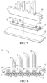
- the controller is on-board the PCB 52, such as controller 128 (such as shown in Figure 7 ).
- the controller may be outside of the vehicle winglet and instead housed within the vehicle itself.
- the controller can be connected to other controllers in a hierarchy, such as an electronic control unit ("ECU").
- the controller may include a processor, memory, and non-volatile storage.
- the processor may include one or more devices selected from microprocessors, micro-controllers, digital signal processors, microcomputers, central processing units, field programmable gate arrays, programmable logic devices, state machines, logic circuits, analog circuits, digital circuits, or any other devices that manipulate signals (analog or digital) based on computer-executable instructions residing in memory.
- the memory may include a single memory device or a plurality of memory devices including, but not limited to, random access memory (“RAM”), volatile memory, non-volatile memory, static random-access memory (“SRAM”), dynamic random-access memory (“DRAM”), flash memory, cache memory, or any other device capable of storing information.
- the non-volatile storage may include one or more persistent data storage devices such as a hard drive, optical drive, tape drive, non-volatile solid-state device, or any other device capable of persistently storing information.
- Executable instructions may include, for example, activating the LEDs in sequence based on a signal indicating the turn signal within the vehicle cabin has been activated by the driver.
Landscapes
- Engineering & Computer Science (AREA)
- General Engineering & Computer Science (AREA)
- Mechanical Engineering (AREA)
- Multimedia (AREA)
- Lighting Device Outwards From Vehicle And Optical Signal (AREA)
- Non-Portable Lighting Devices Or Systems Thereof (AREA)
Description
- The present invention relates to a vehicle winglet. The present invention further relates to a for a vehicle winglet and to a system for sequentially illuminating regions of a vehicle winglet during a turn signal event. This disclosure is generally related to a vehicle winglet with a blinker that illuminates sequentially. In certain embodiments, this disclosure is more specifically related to an external side-view winglet with lights that illuminate sequentially in response to an action taken by the driver of the vehicle, such as activation of a turn signal.
-
EP 1 304 260 A1 relates to a rear-view mirror with multiple interchangeable signals for vehicles. - Passenger vehicles, such as cars, trucks, etc., typically include winglets, such as side mirrors, sideview mirrors, external rearview mirrors, cameras or radars. Vehicle winglets are typically mounted outside the vehicle cabin to allow the driver to see the environment to the side of the vehicle. The winglets may be folded inward when, for example, the vehicle is parked so as to protect the winglets from accidental collision or impact from other vehicles passing by. This may be done by a motor housed within the winglet, for example.
- It has been known to equip the winglets with a lighted turn signal that illuminates. For example, when the driver of the vehicle activates a turn signal indicator (such as a lever), a light within the winglet may correspondingly activate to indicate to other vehicles that the driver intends to turn or change directions. If the driver activates the turn signal indicator so as to indicate an intention to turn left or change direction toward the left, the turn signal within the left-side winglet may correspondingly illuminate. The right-side winglet may have a similar turn signal that illuminates in response to the driver activating the turn signal indicator so as to indicate an intention to turn right or change direction toward the right.
- In one embodiment, a vehicle winglet includes a printed circuit board (PCB) having a plurality of light-emitting diodes (LEDs) disposed thereon. A light guide is connected to and covers the LEDs. The light guide is made of a translucent material and is configured to guide light illuminated by the LEDs and transfer the light out of the light guide. The light guide includes a plurality of light guide towers extending therefrom, each light guide tower aligned with a respective one of the LEDs. In some embodiments, a plurality of collimators are provided, with each collimator aligned with a respective one of the LEDs. The collimators are configured to redirect light illumined from the respective one of the LEDs into a respective one of the light guide towers.
- In another embodiment, a sequential blinker assembly for a vehicle winglet is provided. A cover is coupled to a printed circuit board (PCB). First and second light-emitting diodes (LEDs) are arranged along the PCB, the first and second LEDs configured to illuminate in a sequence. A light guide is coupled to the cover and covering the PCB. The light guide has a main body, a first light guide tower extending from the main body and aligned with the first LED, and a second light guide tower extending from the main body and aligned with the second LED. First and second collimators are provided, with the first collimator aligned with the first LED and configured to redirect light into the first light guide tower, and the second collimator aligned with the second LED and configured to redirect light into the second light guide tower.
- In yet another embodiment, a system for sequentially illuminating regions of a vehicle winglet during a turn signal event is provided. A plurality of light-emitting diodes (LEDs) are configured to illuminate in sequence. A light guide extends over the LEDs, the light guide having a main body and a plurality of light guide towers extending therefrom, each light guide tower aligned with a respective one of the LEDs. A plurality of collimators are provided, with each configured to direct light from a respective one of the LEDs into a respective one of the light guide towers. An outer shell defining a plurality of pockets is configured to receive the light guide towers, wherein the outer shell separates the light guide towers.
-
-
Figure 1 is a front view of a vehicle winglet equipped with a sequential blinker, according to one embodiment. -
Figure 2 is a front view of a vehicle winglet equipped with a sequential blinker, according to another embodiment. -
Figure 3 is a front view of a vehicle winglet equipped with a sequential blinker, according to another embodiment. -
Figure 4 is a front cross-sectional view of a sequential blinker assembly taken from a perspective of a front of the vehicle (i.e., the same perspective asFigures 1-3 ), with the skull cap removed for clarity, according to one embodiment. -
Figure 5 is a side cross-sectional view of the sequential blinker assembly taken along line 5-5 ofFigure 4 , with the skull cap included, according to one embodiment. -
Figure 6 is a top cross-sectional view of the sequential blinker assembly taken along line 6-6 ofFigure 4 , with the skull cap included, according to one embodiment. -
Figure 7 is an exploded perspective view of the sequential blinker assembly ofFigures 4-6 , according to one embodiment. -
Figure 8 is a front cross-sectional view of a sequential blinker assembly taken from a perspective of a front of the vehicle (i.e., the same perspective asFigures 1-3 ), with the skull cap removed for clarity, according to another embodiment. - Embodiments of the present disclosure are described herein. It is to be understood, however, that the disclosed embodiments are merely examples and other embodiments can take various and alternative forms. The Figures are not necessarily to scale; some features could be exaggerated or minimized to show details of particular components. Therefore, specific structural and functional details disclosed herein are not to be interpreted as limiting, but merely as a representative basis for teaching one skilled in the art to variously employ the embodiments. As those of ordinary skill in the art will understand, various features illustrated and described with reference to any one of the Figures can be combined with features illustrated in one or more other Figures to produce embodiments that are not explicitly illustrated or described. The combinations of features illustrated provide representative embodiments for typical applications. Various combinations and modifications of the features consistent with the teachings of this disclosure, however, could be desired for particular applications or implementations.
- Directional terms used herein (e.g., "upper," "lower," "inner," "outer," "top," "bottom," etc.) are intended to refer to the orientation of how the various components are illustrated in the Figures, and how the winglet disclosed herein is oriented relative to an upright vehicle. These terms are intended for contextual purposes.
- This application is directed to a turn signal on a winglet of a vehicle. The vehicle winglet can include an external rearview mirror, a wing mirror, sideview mirror, camera, radar, lidar, or other such terms that refer to a winglet extending outside the vehicle cabin.
- Modern vehicle winglets may be equipped with turn signals that can illuminate. This may be accomplished with a light source such as an incandescent bulb or a light emitting diode (LED). The light source may be placed directly in front of and aligned with a translucent portion of the winglet such that some or all of the light from the light source can pass directly from the light source through the translucent portion. The winglet may also be provided with light reflectors that reflect the light from the light source toward the translucent portion of the winglet. Sequential blinkers are also known in which LEDs are energized in a sequential manner in response to the turn signal switch being activated.
- According to various embodiments described herein, a vehicle winglet is equipped with a sequential blinker provided with an array of light sources (e.g., LEDs) and corresponding light guides. In certain embodiments, each light guide is aligned with a respective one of the light sources, and also includes an optical prism or collimator to align the light from the light source for more effective light being shone through the winglet. The light sources may be arranged on a printed circuit board (PCB) that is connected (e.g., over-molded) with the light guides.
-
Figures 1-3 show examples of sequential turn signals with sequential illumination that can be activated by the methods described herein. For example,Figure 1 illustrates awinglet 10 configured to extend from anexternal side 12 of avehicle 14. Thewinglet 10 includes astrip 16 with a plurality of designs, such asarrows 18 formed thereon. Thearrows 18 may be etched or otherwise formed on thestrip 16. Theentire strip 16 may be translucent, such that some or all light can pass through. Alternatively, only the regions of thestrip 16 where thearrows 18 are located may be translucent. In response to the driver activating the turn signal (in this case, the right turn signal), thearrows 18 illuminate in a sequential pattern, for example in the direction indicated byarrow 20. Once all of thearrows 18 are illuminated, at least some of thearrows 18 may be dimmed or darkened, until one-by-one thearrows 18 are again illuminated in the direction indicated byarrow 20. -
Figure 2 shows another example of sequential illumination of the winglet during a turn-signal event. In this embodiment, awinglet 22 is provided with atranslucent region 24 which may be or include a lens cover. A plurality of illuminatingbars arrow 32 when activated. The bars may increase in size along the direction ofarrow 32;bar 30 may be larger thanbar 28, which may, in turn, be larger thanbar 26. Thus, as thebars - Each
bar translucent region 24 may be optional, and instead the light guides 26, 28, 30, etc. may be interconnected with an exterior surface of askull cap 34 of thewinglet 22. As will be described, eachlight guide Figure 2 ). Thus, as each light source is illuminated, light travels from that light source and up a respective one of the light guides 26, 28, 30, etc. -
Figure 3 is another example of sequential illumination of the winglet during a turn-signal event. Here, awinglet 36 includes a plurality of light guides 38 that collectively form a logo (such as one to identify the brand of the vehicle) when all light guides 38 are illuminated. Separate portions of the logo may be aligned with a respective one of the light sources; for example, using the design "LOGO" shown inFigure 3 , each of the letters "L", "O", "G", and "O" may be aligned with a respective light source (e.g., LED). As the light sources (e.g., LEDs) are activated in the direction of thearrow 40, the full design "LOGO" becomes illuminated. - In another example, the sequential illumination is made in multiple directions, such as from left to right, right to left, middle inside to outside, or combinations of the same. This may be a "welcome" feature when, for example, the driver locks or unlocks the vehicle, the vehicle senses the mobile device (e.g., cellular phone, key fob, wearable device such as a watch, etc.) entering within a certain range of the vehicle, the driver calling for an automatic start of the vehicle, etc. For example, in response to the driver pressing the unlock button on the mobile device, the lights on the winglet illuminate from left to right, and then right to left, and then all lights remain illuminated until the driver enters the vehicle and/or starts the engine. This disclosure is also not limited to only illuminating the lights in a linear fashion; the lights may also illuminate with a strobe light pattern, revolving light pattern, an alternating light pattern, a flashing light, a pulsating light, an oscillating light or any combination thereof. Additionally, references to "illuminating" herein can also mean modulating the power intensity of the lights to create a variable intensity light signal.
-
Figures 1-3 are merely examples of sequential illumination of light sources (e.g., LEDs) and light guides in a vehicle winglet. The remaining Figures illustrate various embodiments of structure configured to provide such sequential illumination. The structure described below can be configured to provide the sequential illumination shown inFigures 1-3 , for example. -
Figures 4-7 illustrate one example of asequential blinker assembly 50 for implementation in any of the winglets described above.Figure 4 shows a front cross-sectional view of thesequential blinker assembly 50 taken from a perspective of a front of the vehicle (i.e., the same perspective asFigures 1-3 ), with askull cap 90 removed for clarity.Figure 5 shows a side cross-sectional view of thesequential blinker assembly 50 taken along line 5-5 ofFigure 4 , with theskull cap 90 included.Figure 6 shows a top cross-sectional view of thesequential blinker assembly 50 taken along line 6-6 ofFigure 4 , with theskull cap 90 included. - Referring to
Figures 4-7 , thesequential blinker assembly 50 includes a plurality of components assembled together, including a PCB with light sources, a light guide, a cover, electrical connects, etc., that will be described below. In the illustrated embodiment, thesequential blinker assembly 50 includes aPCB 52 powered by an external power source (not shown) via anelectrical connector 54, such as an electrically-conductive pathway like a copper wire, coupled to thePCB 52. - The
PCB 52 supports and delivers power to a plurality of light sources. The light sources can includeLEDs PCB 52. Spaced above thePCB 52 is alight guide 68. Thelight guide 68 is configured to transmit the light emitting from the LEDs with high light transmissivity and low light loss. - The
light guide 68 may be a molded, single-piece component made of a plastic, such as acrylic or polycarbonate for example. Thelight guide 68 has a plurality of light guide towers, such aslight guide tower light guide tower 70 is aligned withLED 60,light guide tower 72 is aligned withLED 62,light guide tower 74 is aligned withLED 64, andlight guide tower 76 is aligned withLED 66. The light guide towers 70-76 may extend vertically away from the main body of thelight guide 68, and may be horizontally separated from one another by air, the skull cap 90 (described below), or other structure to give the appearance of a separate illuminated bar or strip as each LED is illuminated. - The
light guide 68 may be connected to acover 78. Thecover 78 may support thePCB 52 from beneath, or may be spaced vertically from thePCB 52. Thelight guide 68 can be connected to thecover 78 in multiple locations by a snap-fit or via fasteners during assembly. Thecover 78 may also extend beneath thelight guide 68 and wrap around the rear of thelight guide 68, as shown inFigure 5 . Thecover 78 may be made of any suitable material configured for light-weight support (e.g., plastic), and may be indirectly or directly mounted to other parts of the winglet for proper fixation of thesequential blinker assembly 50. - As mentioned above, each light guide tower 70-76 is aligned vertically with a respective one of the LEDs 60-66. Thus, when each of the LEDs 60-66 are individually illuminated during operation of the sequential blinker (e.g., from left to right in
Figure 4 ), light is correspondingly guided through each respective light guide tower 70-76 sequentially. These light guide towers 70-76 are visible from the outside of the vehicle, and provide the appearance of a sequential blinker (such as shown inFigures 1-3 ) as the light guide towers 70-76 are sequentially illuminated. The light guide towers 70-76 may also be covered and aligned with a translucent strip (such as those described above with reference toFigures 1-3 ) such that illumination of each light guide tower 70-76 illuminates a respective pattern, such as an arrow, a letter, a portion of a logo, the "welcome" feature described above, etc. - The
light guide 68 may also be provided with collimators to help guide the light. For example, thelight guide 68 may have a plurality ofcollimators light guide 68. The collimators 80-86 are convex lens-shaped features that can narrow the light emitted from each of the LEDs 60-66, causing the direction of motion of the light from each LED to be more parallel as the light moves toward the light guide towers 70-76. As each LED 60-66 is illuminated, the light hits a respective collimator 80-86 to travel vertically into a respective light guide tower 70-76. With the help of the collimators 80-86, thesequential blinker assembly 50 has a designated light guide tower 70-76 for each LED 60-66 as the LEDs are illumined sequentially. - Vehicle winglets, or side mirrors, can also include a skull cap, known in the art. Skull caps typically are the outer-most shell or housing component of a winglet. Skull caps typically cover an upper portion of the winglet, and fasten to another shell component either beneath the skull cap or on the side of the vehicle.
-
Figures 5 and 6 show one embodiment of theskull cap 90 for attachment to thesequential blinker assembly 50. Theskull cap 90 can be formed to include a plurality of indentations or pockets 92. Eachpocket 92 is sized and configured to receive a respective one of the light guide towers 70-76. As shown in the view ofFigure 6 , this can create an undulating or serpentine shape of theskull cap 90 with intermittent locations of light guide towers 70-76. - The
skull cap 90 may contact and partially surround the rear, unexposed side of the light guide towers 70-76. Each of the light guide towers 70-76 may include surface features to engage theskull cap 90. For example, referring toFigure 5 , thelight guide tower 76 includes arear surface 94 that includes corrugated or ribbed surface features. This can facilitate a connection to afront surface 96 of theskull cap 90. An adhesive may be provided in the area between therear surface 94 of thelight guide tower 76 and thefront surface 96 of theskull cap 90. - The
sequential blinker assembly 50 can also include a frame orhousing 98. Thehousing 98 is located beneath theskull cap 90 and can fasten or otherwise secure to theskull cap 90. Thehousing 98 can also support and/or attach to the light guide towers 70-76 from beneath. The combination of thehousing 98 and theskull cap 90 can encapsulate the sequential blinker within the winglet. - Referring back to
Figure 4 , thesequential blinker assembly 50 also includes an additional light source orLED 100 positioned on thePCB 52. Theadditional LED 100 is not aligned with a respective light guide tower 70-76, but it is instead aligned with anoptics prism 102 formed by surface features on thelight guide 68. Theoptics prism 102 includes a plurality of inclined, angled, or tapered surfaces that facilitate the distribution of light from theadditional LED 100 in many multiple directions. This allows the light from theadditional LED 100 to be sent through thelight guide 68 at various angles, creating a full, consistent illumination of the entirelight guide 68 when theadditional LED 100 is activated. In other words, theoptics prism 102 allows the activation of theadditional LED 100 to illuminate a majority of thelight guide 68, as opposed to the collimators 80-86 which specifically direct the light in a single direction (e.g., up the light guide towers 70-76). In one embodiment, theadditional LED 100 is activated sequentially after all of the other LEDs 60-66 have been activated to create a more full, brighter light throughout thelight guide 68. In another embodiment, theadditional LED 100 is activated sequentially before any of the other LEDs 60-66 are activated to create a general full-body light in thelight guide 68 before each light guide tower 70-76 is more brightly illuminated in sequence. -
Figure 8 illustrates another example of asequential blinker assembly 120. The sequential blinker assembly includes identical or similar structure as the embodiment ofFigures 4-7 unless otherwise described below. Thesequential blinker assembly 120 includes the LEDs 60-66 and theadditional LED 100, along with light guide towers 70-76 as in the previous embodiment. In this embodiment, alight guide 122 is over-molded onto thecover 78. This provides a molded connection between thelight guide 122 and thecover 78 that is made during formation of thelight guide 122. - Also in this embodiment, the optics prism and one or more of the collimators are not formed as integral features of the light guide, but are rather separately connected. For example, one or more of the collimators, such as
collimator 124, can be adhered, fastened, or otherwise secured within thelight guide 122. Thelight guide 122 can also be over-molded onto one or more of thecollimator 124. Likewise, anoptics prism 126 can be adhered, fastened, or otherwise secured within thelight guide 122. Thelight guide 122 can also be over-molded onto theoptics prism 126. As can be seen inFigure 8 , the over-moldedlight guide 122 includesregions 123 that fill the space between eachrespective collimator 124. In contrast, thelight guide 68 in the embodiment ofFigure 4 includes legs that extend downward on either side of each LED 60-66. - It should be understood that some of the features of the various embodiments disclosed above can be combined to form new embodiments of the sequential blinker assembly.
- While not shown in the Figures, the LEDs are selectively illuminated by commands sent from a controller. The controller is on-board the
PCB 52, such as controller 128 (such as shown inFigure 7 ). Alternatively, in an embodiment not covered by the claims, the controller may be outside of the vehicle winglet and instead housed within the vehicle itself. The controller can be connected to other controllers in a hierarchy, such as an electronic control unit ("ECU"). The controller may include a processor, memory, and non-volatile storage. The processor may include one or more devices selected from microprocessors, micro-controllers, digital signal processors, microcomputers, central processing units, field programmable gate arrays, programmable logic devices, state machines, logic circuits, analog circuits, digital circuits, or any other devices that manipulate signals (analog or digital) based on computer-executable instructions residing in memory. The memory may include a single memory device or a plurality of memory devices including, but not limited to, random access memory ("RAM"), volatile memory, non-volatile memory, static random-access memory ("SRAM"), dynamic random-access memory ("DRAM"), flash memory, cache memory, or any other device capable of storing information. The non-volatile storage may include one or more persistent data storage devices such as a hard drive, optical drive, tape drive, non-volatile solid-state device, or any other device capable of persistently storing information. Executable instructions may include, for example, activating the LEDs in sequence based on a signal indicating the turn signal within the vehicle cabin has been activated by the driver. - While exemplary embodiments are described above, it is not intended that these embodiments describe all possible forms encompassed by the claims. The words used in the specification are words of description rather than limitation. As previously described, the features of various embodiments can be combined to form further embodiments of the invention that may not be explicitly described or illustrated. While various embodiments could have been described as providing advantages or being preferred over other embodiments or prior art implementations with respect to one or more desired characteristics, those of ordinary skill in the art recognize that one or more features or characteristics can be compromised to achieve desired overall system attributes, which depend on the specific application and implementation. These attributes can include, but are not limited to cost, strength, durability, life cycle cost, marketability, appearance, packaging, size, serviceability, weight, manufacturability, ease of assembly, etc. As such, to the extent any embodiments are described as less desirable than other embodiments or prior art implementations with respect to one or more characteristics, these embodiments are not outside the scope of the disclosure and can be desirable for particular applications.
List of used reference signs winglet 10 external side 12 vehicle 14 arrows 18 direction 20 winglet 22 translucent region 24 illuminating bars 26, 28, 30 direction of arrow 32 skull cap 34 winglet 36 light guides 38 direction 40 sequential blinker assembly 50 PCB 52 electrical connector 54 LEDs 60, 62, 64, 66 light guide 68 light guide tower 70, 72, 74, 76 cover 78 collimators 80, 82, 84, 86 skull cap 90 pocket 92 rear surface 94 front surface 96 housing 98 LED 100 optics prism 102 sequential blinker assembly 120 light guide 122 collimator 124 prism 126
Claims (13)
- A vehicle winglet (10, 22, 36) equipped with a sequential blinker and comprising:a printed circuit board -PCB - (52) having a plurality of light-emitting diodes - LEDs - (60, 62, 64, 66) disposed thereon; anda light guide (38, 68, 122) connected to and covering the LEDs (60, 62, 64, 66),the light guide (38, 68, 122) made of a translucent material and configured to guide light illuminated by the LEDs (60, 62, 64, 66) and transfer the light out of the light guide (38, 68, 122),the light guide (38, 68, 122) including a plurality of light guide towers (70, 72, 74, 76) extending therefrom,each light guide tower (70, 72, 74, 76) aligned with a respective one of the LEDs (60, 62, 64, 66; 100),wherein each of the LEDs (60, 62, 64, 66) are individually illuminated during operation of the sequential blinker, light is correspondingly guided through each respective light guide tower (70, 72, 74, 76) sequentially; andthe winglet further comprising a controller on-board the PCB (52) and configured to sequentially illuminate the LEDs (60, 62, 64, 66) in response to a signal indicating a turn signal has been activated or in response to a lock or unlock signal received from a mobile device,wherein the winglet (10, 22, 36) further comprises an additional LED (100) disposed on the PCB (52),wherein the additional LED (100) is not aligned with a light guide tower, andwherein the light guide (38, 68, 122) includes an optics prism (102, 126) aligned with the additional LED (100), wherein the optics prism (102, 126) comprises a plurality of inclined, angled or tapered surfaces configured to facilitate the distribution of light emitted from the additional LED (100) throughout the light guide (38, 68, 122).
- The vehicle winglet of claim 1, further comprising a plurality of collimators (80, 82, 84, 86), each collimator (80, 82, 84, 86) aligned with a respective one of the LEDs (100) and configured to redirect light illuminated from the respective one of the LEDs (100) into a respective one of the light guide towers (70, 72, 74, 76).
- The vehicle winglet according to any of the preceding claims, further comprising a skull cap (34, 90) formed with a plurality of pockets (92) configured to receive the light guide towers (70, 72, 74, 76).
- The vehicle winglet of claim 3, wherein the light guide towers (70, 72, 74, 76) are separated from each other by the skull cap (34, 90), and wherein the skull cap (34, 90) and the light guide towers (70, 72, 74, 76) collectively form an external surface of the vehicle winglet (10, 22, 36).
- The vehicle winglet according to any of the claims 2 to 4, wherein each collimator (80, 82, 84, 86) includes a convex surface facing a respective one of the LEDs (60, 62, 64, 66; 100) to inhibit the light from the respective LED (60, 62, 64, 66) from distributing throughout the light guide (38, 68, 122) and instead be directed to a respective one of the light guide towers (70, 72, 74, 76).
- The vehicle winglet of claim 5, wherein each collimator is formed as an integral part of the light guide (38, 68, 122) and is defined by surface of the light guide (38, 68, 122).
- The vehicle winglet of claim 5 or 6, wherein a cover (78) is over-molded to at least partially surround the PCB (52) and the light guide (38, 68, 122).
- The vehicle winglet of claim 1, wherein the additional LED (60, 62, 64, 66) is configured to illuminate in the sequence in response to a signal indicating a turn signal has been activated or in response to a lock or unlock signal received from a mobile device.
- A sequential blinker assembly (50, 120) for a vehicle winglet (10, 22, 36), in particular for a vehicle winglet (10, 22, 36) according to any of the claims 1-9, the sequential blinker assembly (50, 120) comprising:a cover (78);a printed circuit board - PCB - (52) coupled to the cover (78);first and second light-emitting diodes - LEDs - (60, 62, 64, 66) arranged along the PCB (52), the first and second LEDs (60, 62, 64, 66) configured to illuminate in a sequence;a light guide (38, 68, 122) coupled to the cover (78) and covering the PCB (52), the light guide (38, 68, 122) having a main body, a first light guide tower (70, 72, 74, 76) extending from the main body and aligned with the first LED (60, 62, 64, 66), and a second light guide tower (70, 72, 74, 76) extending from the main body and aligned with the second LED (60, 62, 64, 66); andfirst and second collimators (80, 82, 84, 86), the first collimator (80, 82, 84, 86) aligned with the first LED (60, 62, 64, 66) and configured to redirect light into the first light guide tower (70, 72, 74, 76), and the second collimator (80, 82, 84, 86) aligned with the second LED (60, 62, 64, 66) and configured to redirect light into the second light guide tower (70, 72, 74, 76),wherein each of the first and second LEDs (60, 62, 64, 66) are individually illuminated during operation of the sequential blinker assembly (50, 120), light is correspondingly guided through each respective first and second light guide tower (70, 72, 74, 76) sequentially; andthe blinker assembly (50, 120) further comprising a controller on-board the PCB (52) and configured to sequentially illuminate the LEDs (60, 62, 64, 66) in response to a signal indicating a turn signal has been activated or in response to a lock or unlock signal received from a mobile device,wherein the blinker further comprises a third LED (100) aligned with the light guide (38, 68, 122),wherein the light guide (38, 68, 122) does not include a third light guide tower aligned with the third LED (100), andwherein an optics prism (102, 126) is aligned with the third LED (100) and comprises a plurality of inclined, angled or tapered surfaces configured to facilitate light emitted from the third LED (100) to distribute through the light guide (38, 68, 122).
- The sequential blinker assembly of claim 9, wherein the first and second collimators (80, 82, 84, 86) are formed as an integral part of the light guide (38, 68, 122), and/or wherein the light guide (38, 68, 122) is over-molded onto the cover (78).
- The sequential blinker assembly of claim 9 or 10, further comprising:
a skull cap (34, 90) coupled to the cover (78), the skull cap (34, 90) including a first pocket (92) that receives the first light guide tower (70, 72, 74, 76), and a second pocket (92) that receives the second light guide tower (70, 72, 74, 76), wherein the first and second light guide towers (70, 72, 74, 76) are separated from each other by the skull cap (34, 90). - A system for sequentially illuminating regions of a vehicle winglet (10, 22, 36) equipped with a sequential blinker during a turn signal event, in particular of a vehicle winglet (10, 22, 36) according to any of the claims 1-9, the system comprising:a plurality of light-emitting diodes - LEDs - (60, 62, 64, 66) configured to illuminate in sequence;a light guide (38, 68, 122) extending over the LEDs (60, 62, 64, 66), the light guide (38, 68, 122) having a main body and a plurality of light guide towers (70, 72, 74, 76) extending therefrom, each light guide tower (70, 72, 74, 76) aligned with a respective one of the LEDs (60, 62, 64, 66);a plurality of collimators (80, 82, 84, 86), each configured to direct light from a respective one of the LEDs (60, 62, 64, 66) into a respective one of the light guide towers (70, 72, 74, 76); andan outer shell defining a plurality of pockets (92) configured to receive the light guide towers (70, 72, 74, 76), wherein the outer shell separates the light guide towers (70, 72, 74, 76),wherein each of the LEDs (60, 62, 64, 66) are individually illuminated during operation of the system, light is correspondingly guided through each respective light guide tower (70, 72, 74, 76) sequentially;the system further comprising a controller configured to sequentially illuminate the LEDs (60, 62, 64, 66) in response to a signal indicating a turn signal has been activated or in response to a lock or unlock signal received from a mobile device; andwherein the system further comprises an additional LED (100) disposed on the PCB (52),wherein the additional LED (100) is not aligned with a light guide tower, andwherein the light guide (38, 68, 122) includes an optics prism (102, 126) aligned with the additional LED (100), wherein the optics prism (102, 126) comprises a plurality of inclined, angled or tapered surfaces configured to facilitate the distribution of light emitted from the additional LED (100) throughout the light guide (38, 68, 122).
- The system of claim 12, wherein:each light guide tower (70, 72, 74, 76) includes a rear surface (94) with ribbed surface features facing a front surface (96) of the outer shell, and/orthe pockets (92) collectively create a serpentine shape of the outer shell that holds the light guide towers (70, 72, 74, 76) in separation, and/orthe LEDs (60, 62, 64, 66) are aligned along a direction and wherein each light guide tower (70, 72, 74, 76) increases in height along the direction.
Applications Claiming Priority (1)
| Application Number | Priority Date | Filing Date | Title |
|---|---|---|---|
| US16/225,159 US10780819B2 (en) | 2018-12-19 | 2018-12-19 | Vehicle winglet with sequential blinker |
Publications (2)
| Publication Number | Publication Date |
|---|---|
| EP3671018A1 EP3671018A1 (en) | 2020-06-24 |
| EP3671018B1 true EP3671018B1 (en) | 2024-12-18 |
Family
ID=69410941
Family Applications (1)
| Application Number | Title | Priority Date | Filing Date |
|---|---|---|---|
| EP19218153.5A Active EP3671018B1 (en) | 2018-12-19 | 2019-12-19 | Vehicle winglet, sequential blinker assembly and system for sequentially illuminating regions of a vehicle winglet |
Country Status (3)
| Country | Link |
|---|---|
| US (1) | US10780819B2 (en) |
| EP (1) | EP3671018B1 (en) |
| CN (1) | CN111332191B (en) |
Families Citing this family (9)
| Publication number | Priority date | Publication date | Assignee | Title |
|---|---|---|---|---|
| DE102018106035A1 (en) * | 2018-03-15 | 2019-09-19 | HELLA GmbH & Co. KGaA | Lighting device for vehicles |
| CN111457275B (en) * | 2019-01-18 | 2025-04-18 | 深圳市绎立锐光科技开发有限公司 | A lighting device |
| JP7515244B2 (en) * | 2019-09-30 | 2024-07-12 | スタンレー電気株式会社 | Vehicle lighting control device and lighting control method, vehicle lighting system |
| JP7345339B2 (en) * | 2019-09-30 | 2023-09-15 | スタンレー電気株式会社 | Lighting control device and lighting control method for vehicle lights, vehicle light system |
| JP7814206B2 (en) * | 2022-03-22 | 2026-02-16 | スタンレー電気株式会社 | Vehicle display device |
| EP4253149B1 (en) * | 2022-03-31 | 2024-09-25 | Motherson Innovations Company Limited | Logo lamp device, rear view system, vehicle and method for assembling |
| CN117628423A (en) * | 2022-08-12 | 2024-03-01 | 巨铠精密工业股份有限公司 | lamps |
| US12000581B1 (en) * | 2022-12-02 | 2024-06-04 | Goodrich Corporation | Exterior decorative lighting |
| US12338978B1 (en) * | 2024-04-16 | 2025-06-24 | Illumination Enterprises Inc. | Track lighting system and luminaire with multiple LEDs |
Citations (1)
| Publication number | Priority date | Publication date | Assignee | Title |
|---|---|---|---|---|
| US20130242586A1 (en) * | 2010-10-01 | 2013-09-19 | Magna Mirrors Of America, Inc. | Vehicle exterior mirror system with light module |
Family Cites Families (28)
| Publication number | Priority date | Publication date | Assignee | Title |
|---|---|---|---|---|
| US6152590A (en) * | 1998-02-13 | 2000-11-28 | Donnelly Hohe Gmbh & Co. Kg | Lighting device for motor vehicles |
| US6511192B1 (en) | 1999-12-17 | 2003-01-28 | Britax Vision Systems (North America) Inc. | Side view mirror with integral lighting |
| ES2168071B1 (en) | 2000-07-12 | 2003-07-16 | Barros Alejandro Rodriguez | MODULAR REAR VIEW MIRROR WITH INTERCHANGEABLE MULTIPLE SIGNALS FOR VEHICLES OF 2, 3, 4 OR MORE WHEELS. |
| US20030007362A1 (en) * | 2001-07-05 | 2003-01-09 | Robison David L. | Vehicle side mirror assembly including sequentially lighted LED turn signal indicator |
| US6880960B2 (en) | 2003-03-26 | 2005-04-19 | E'sam Co., Ltd. | Side mirror cover and side mirror body |
| ES2247909B1 (en) | 2004-02-02 | 2007-05-16 | Matias Mandagaran Rodriguez | SIGNAL ISSUER ASSEMBLY FOR VEHICLE MIRROR COMPOSED OF SEVERAL LED CONTROLLED SEQUENTIALLY ACCORDING TO YOUR RUNNING. |
| US7588358B1 (en) | 2005-05-31 | 2009-09-15 | Innovative Lighting, Inc | Single LED and lens assembly |
| US7717596B1 (en) | 2005-07-15 | 2010-05-18 | Alan Bell | Rearview mirror assembly with running lights |
| US7670039B2 (en) * | 2006-03-17 | 2010-03-02 | Lutron Electronics Co., Inc. | Status indicator lens and light pipe structure for a dimmer switch |
| DE502007000029D1 (en) * | 2006-05-11 | 2008-08-14 | Visiocorp Patents Sarl | Luminaire unit and exterior mirror with one luminaire unit |
| JP4806594B2 (en) | 2006-06-15 | 2011-11-02 | サカエ理研工業株式会社 | VEHICLE LIGHT AND VEHICLE DOOR MIRROR HAVING THE VEHICLE LIGHT |
| DE102007019688A1 (en) * | 2007-04-24 | 2008-10-30 | Hella Kgaa Hueck & Co. | Signal light for motor vehicles, has housing, in which light source unit and multiple light conducting elements are assigned to light source unit and housing is covered by translucent sealing disk |
| ES2335332B1 (en) | 2008-01-16 | 2011-01-07 | Alejandro Rodriguez Barros | ASSEMBLY OF MULTISEÑAL EXTERIOR REAR VIEW MIRROR OF A VEHICLE. |
| US9102281B2 (en) * | 2008-01-16 | 2015-08-11 | Alejandro Rodriguez Barros | Rear-view mirror for a vehicle with a set of indicator lights |
| JP5425443B2 (en) * | 2008-10-31 | 2014-02-26 | 株式会社ミツバ | Vehicle lamp |
| ES2383404B1 (en) | 2008-11-13 | 2013-06-20 | Alejandro Rodriguez Barros | MULTIFUNCTION EXTERIOR REAR VIEW MIRROR ASSEMBLY FOR VEHICLES |
| CN103899956A (en) * | 2009-06-18 | 2014-07-02 | 株式会社S.K.G. | Illumination device |
| WO2011148420A1 (en) * | 2010-05-26 | 2011-12-01 | 株式会社エス・ケー・ジー | Illumination device |
| EP2390136A1 (en) * | 2010-05-31 | 2011-11-30 | Fico Mirrors, S.A. | Assembly having a housing comprising a circuit board supporting a plurality of light emitting diodes |
| JP2013122872A (en) | 2011-12-12 | 2013-06-20 | Koito Mfg Co Ltd | Illumination lamp fitting for vehicle |
| US9321395B2 (en) * | 2013-04-26 | 2016-04-26 | Ford Global Technologies, Llc | Vehicle puddle lamp assembly generating animated image and method |
| KR101451861B1 (en) | 2014-03-14 | 2014-10-16 | 에스엘 주식회사 | Lamp for vehicle |
| JP6445818B2 (en) * | 2014-09-19 | 2018-12-26 | 株式会社小糸製作所 | Vehicle lighting |
| CN204774912U (en) * | 2015-03-17 | 2015-11-18 | 麦格纳(太仓)汽车科技有限公司 | Vehicle lane change warns lamps and lanterns |
| KR101755866B1 (en) * | 2015-10-23 | 2017-07-10 | 현대자동차주식회사 | Light source module of lamp for vehicle |
| US10119676B2 (en) | 2016-06-10 | 2018-11-06 | Osram Gmbh | Lighting device, corresponding lamp and method |
| CZ201793A3 (en) * | 2017-02-17 | 2018-08-29 | Varroc Lighting Systems, s.r.o. | A lighting device, in particular a signal lamp for motor vehicles |
| WO2018162037A1 (en) * | 2017-03-07 | 2018-09-13 | HELLA GmbH & Co. KGaA | Lighting device for vehicles |
-
2018
- 2018-12-19 US US16/225,159 patent/US10780819B2/en active Active
-
2019
- 2019-12-18 CN CN201911308291.XA patent/CN111332191B/en active Active
- 2019-12-19 EP EP19218153.5A patent/EP3671018B1/en active Active
Patent Citations (1)
| Publication number | Priority date | Publication date | Assignee | Title |
|---|---|---|---|---|
| US20130242586A1 (en) * | 2010-10-01 | 2013-09-19 | Magna Mirrors Of America, Inc. | Vehicle exterior mirror system with light module |
Also Published As
| Publication number | Publication date |
|---|---|
| CN111332191B (en) | 2022-01-11 |
| US20200198530A1 (en) | 2020-06-25 |
| CN111332191A (en) | 2020-06-26 |
| EP3671018A1 (en) | 2020-06-24 |
| US10780819B2 (en) | 2020-09-22 |
Similar Documents
| Publication | Publication Date | Title |
|---|---|---|
| EP3671018B1 (en) | Vehicle winglet, sequential blinker assembly and system for sequentially illuminating regions of a vehicle winglet | |
| US12139086B2 (en) | Vehicle bumper assembly | |
| US11054105B2 (en) | Lamp and vehicle having same | |
| US11231157B2 (en) | Lighting device for a vehicle, in particular an electric vehicle | |
| US9771016B2 (en) | Vehicle light apparatus | |
| US6250784B1 (en) | Vehicular wing mirror having a light-transmitting housing | |
| US6929390B2 (en) | Vehicular lamp | |
| US6461028B1 (en) | Vehicle side bumper and signal light assembly | |
| US6932497B1 (en) | Signal light and rear-view mirror arrangement | |
| CN106195847B (en) | Mood light for vehicle | |
| US20210370821A1 (en) | Vehicle light assembly | |
| JP2005502164A (en) | Car lamp assembly with heat sink | |
| US7220030B2 (en) | Exterior mirror having lamp and exterior rear-view mirror having lamp | |
| US12429189B2 (en) | Mini or micro LED-based light module configured to perform plural light functions seamlessly with different light guides in unitary assembly | |
| US7407311B2 (en) | Light with a ring structure for a vehicle lamp | |
| US9303838B2 (en) | Vehicle light and vehicle equipped with vehicle light | |
| KR20120067435A (en) | Lamp for a motor vehicle | |
| US20070081350A1 (en) | Rearview mirror and signal light arrangement | |
| JP2002334604A (en) | Bulbs for headlights, etc. | |
| US20210396373A1 (en) | Pedestrian communication vehicle fog lamp | |
| US7656283B2 (en) | Vehicle recognizing apparatus | |
| CN112984458A (en) | Opaque outer lens with integrated optical element | |
| KR20040097076A (en) | Flash Light Safety Helmet For Confirm Location And Alarm Signal | |
| CN115711371A (en) | Vehicle exterior lighting system with exposable fender lamp assembly | |
| CN116997484A (en) | Lighting devices for motor vehicles |
Legal Events
| Date | Code | Title | Description |
|---|---|---|---|
| PUAI | Public reference made under article 153(3) epc to a published international application that has entered the european phase |
Free format text: ORIGINAL CODE: 0009012 |
|
| STAA | Information on the status of an ep patent application or granted ep patent |
Free format text: STATUS: THE APPLICATION HAS BEEN PUBLISHED |
|
| AK | Designated contracting states |
Kind code of ref document: A1 Designated state(s): AL AT BE BG CH CY CZ DE DK EE ES FI FR GB GR HR HU IE IS IT LI LT LU LV MC MK MT NL NO PL PT RO RS SE SI SK SM TR |
|
| AX | Request for extension of the european patent |
Extension state: BA ME |
|
| STAA | Information on the status of an ep patent application or granted ep patent |
Free format text: STATUS: REQUEST FOR EXAMINATION WAS MADE |
|
| 17P | Request for examination filed |
Effective date: 20201218 |
|
| RBV | Designated contracting states (corrected) |
Designated state(s): AL AT BE BG CH CY CZ DE DK EE ES FI FR GB GR HR HU IE IS IT LI LT LU LV MC MK MT NL NO PL PT RO RS SE SI SK SM TR |
|
| STAA | Information on the status of an ep patent application or granted ep patent |
Free format text: STATUS: EXAMINATION IS IN PROGRESS |
|
| 17Q | First examination report despatched |
Effective date: 20220810 |
|
| GRAP | Despatch of communication of intention to grant a patent |
Free format text: ORIGINAL CODE: EPIDOSNIGR1 |
|
| STAA | Information on the status of an ep patent application or granted ep patent |
Free format text: STATUS: GRANT OF PATENT IS INTENDED |
|
| INTG | Intention to grant announced |
Effective date: 20240712 |
|
| GRAS | Grant fee paid |
Free format text: ORIGINAL CODE: EPIDOSNIGR3 |
|
| GRAA | (expected) grant |
Free format text: ORIGINAL CODE: 0009210 |
|
| STAA | Information on the status of an ep patent application or granted ep patent |
Free format text: STATUS: THE PATENT HAS BEEN GRANTED |
|
| AK | Designated contracting states |
Kind code of ref document: B1 Designated state(s): AL AT BE BG CH CY CZ DE DK EE ES FI FR GB GR HR HU IE IS IT LI LT LU LV MC MK MT NL NO PL PT RO RS SE SI SK SM TR |
|
| REG | Reference to a national code |
Ref country code: CH Ref legal event code: EP |
|
| REG | Reference to a national code |
Ref country code: DE Ref legal event code: R096 Ref document number: 602019063585 Country of ref document: DE |
|
| REG | Reference to a national code |
Ref country code: IE Ref legal event code: FG4D |
|
| REG | Reference to a national code |
Ref country code: LT Ref legal event code: MG9D |
|
| PG25 | Lapsed in a contracting state [announced via postgrant information from national office to epo] |
Ref country code: HR Free format text: LAPSE BECAUSE OF FAILURE TO SUBMIT A TRANSLATION OF THE DESCRIPTION OR TO PAY THE FEE WITHIN THE PRESCRIBED TIME-LIMIT Effective date: 20241218 |
|
| PG25 | Lapsed in a contracting state [announced via postgrant information from national office to epo] |
Ref country code: FI Free format text: LAPSE BECAUSE OF FAILURE TO SUBMIT A TRANSLATION OF THE DESCRIPTION OR TO PAY THE FEE WITHIN THE PRESCRIBED TIME-LIMIT Effective date: 20241218 |
|
| PG25 | Lapsed in a contracting state [announced via postgrant information from national office to epo] |
Ref country code: BG Free format text: LAPSE BECAUSE OF FAILURE TO SUBMIT A TRANSLATION OF THE DESCRIPTION OR TO PAY THE FEE WITHIN THE PRESCRIBED TIME-LIMIT Effective date: 20241218 |
|
| PG25 | Lapsed in a contracting state [announced via postgrant information from national office to epo] |
Ref country code: NO Free format text: LAPSE BECAUSE OF FAILURE TO SUBMIT A TRANSLATION OF THE DESCRIPTION OR TO PAY THE FEE WITHIN THE PRESCRIBED TIME-LIMIT Effective date: 20250318 |
|
| REG | Reference to a national code |
Ref country code: NL Ref legal event code: MP Effective date: 20241218 |
|
| PG25 | Lapsed in a contracting state [announced via postgrant information from national office to epo] |
Ref country code: GR Free format text: LAPSE BECAUSE OF FAILURE TO SUBMIT A TRANSLATION OF THE DESCRIPTION OR TO PAY THE FEE WITHIN THE PRESCRIBED TIME-LIMIT Effective date: 20250319 Ref country code: LV Free format text: LAPSE BECAUSE OF FAILURE TO SUBMIT A TRANSLATION OF THE DESCRIPTION OR TO PAY THE FEE WITHIN THE PRESCRIBED TIME-LIMIT Effective date: 20241218 |
|
| PG25 | Lapsed in a contracting state [announced via postgrant information from national office to epo] |
Ref country code: RS Free format text: LAPSE BECAUSE OF FAILURE TO SUBMIT A TRANSLATION OF THE DESCRIPTION OR TO PAY THE FEE WITHIN THE PRESCRIBED TIME-LIMIT Effective date: 20250318 |
|
| PG25 | Lapsed in a contracting state [announced via postgrant information from national office to epo] |
Ref country code: NL Free format text: LAPSE BECAUSE OF FAILURE TO SUBMIT A TRANSLATION OF THE DESCRIPTION OR TO PAY THE FEE WITHIN THE PRESCRIBED TIME-LIMIT Effective date: 20241218 |
|
| REG | Reference to a national code |
Ref country code: AT Ref legal event code: MK05 Ref document number: 1752486 Country of ref document: AT Kind code of ref document: T Effective date: 20241218 |
|
| PG25 | Lapsed in a contracting state [announced via postgrant information from national office to epo] |
Ref country code: SM Free format text: LAPSE BECAUSE OF FAILURE TO SUBMIT A TRANSLATION OF THE DESCRIPTION OR TO PAY THE FEE WITHIN THE PRESCRIBED TIME-LIMIT Effective date: 20241218 |
|
| PG25 | Lapsed in a contracting state [announced via postgrant information from national office to epo] |
Ref country code: PL Free format text: LAPSE BECAUSE OF FAILURE TO SUBMIT A TRANSLATION OF THE DESCRIPTION OR TO PAY THE FEE WITHIN THE PRESCRIBED TIME-LIMIT Effective date: 20241218 |
|
| PG25 | Lapsed in a contracting state [announced via postgrant information from national office to epo] |
Ref country code: ES Free format text: LAPSE BECAUSE OF FAILURE TO SUBMIT A TRANSLATION OF THE DESCRIPTION OR TO PAY THE FEE WITHIN THE PRESCRIBED TIME-LIMIT Effective date: 20241218 |
|
| PG25 | Lapsed in a contracting state [announced via postgrant information from national office to epo] |
Ref country code: IS Free format text: LAPSE BECAUSE OF FAILURE TO SUBMIT A TRANSLATION OF THE DESCRIPTION OR TO PAY THE FEE WITHIN THE PRESCRIBED TIME-LIMIT Effective date: 20250418 |
|
| PG25 | Lapsed in a contracting state [announced via postgrant information from national office to epo] |
Ref country code: PT Free format text: LAPSE BECAUSE OF FAILURE TO SUBMIT A TRANSLATION OF THE DESCRIPTION OR TO PAY THE FEE WITHIN THE PRESCRIBED TIME-LIMIT Effective date: 20250421 |
|
| PG25 | Lapsed in a contracting state [announced via postgrant information from national office to epo] |
Ref country code: EE Free format text: LAPSE BECAUSE OF FAILURE TO SUBMIT A TRANSLATION OF THE DESCRIPTION OR TO PAY THE FEE WITHIN THE PRESCRIBED TIME-LIMIT Effective date: 20241218 |
|
| PG25 | Lapsed in a contracting state [announced via postgrant information from national office to epo] |
Ref country code: AT Free format text: LAPSE BECAUSE OF FAILURE TO SUBMIT A TRANSLATION OF THE DESCRIPTION OR TO PAY THE FEE WITHIN THE PRESCRIBED TIME-LIMIT Effective date: 20241218 Ref country code: RO Free format text: LAPSE BECAUSE OF FAILURE TO SUBMIT A TRANSLATION OF THE DESCRIPTION OR TO PAY THE FEE WITHIN THE PRESCRIBED TIME-LIMIT Effective date: 20241218 |
|
| PG25 | Lapsed in a contracting state [announced via postgrant information from national office to epo] |
Ref country code: SK Free format text: LAPSE BECAUSE OF FAILURE TO SUBMIT A TRANSLATION OF THE DESCRIPTION OR TO PAY THE FEE WITHIN THE PRESCRIBED TIME-LIMIT Effective date: 20241218 |
|
| PG25 | Lapsed in a contracting state [announced via postgrant information from national office to epo] |
Ref country code: CZ Free format text: LAPSE BECAUSE OF FAILURE TO SUBMIT A TRANSLATION OF THE DESCRIPTION OR TO PAY THE FEE WITHIN THE PRESCRIBED TIME-LIMIT Effective date: 20241218 |
|
| PG25 | Lapsed in a contracting state [announced via postgrant information from national office to epo] |
Ref country code: IT Free format text: LAPSE BECAUSE OF FAILURE TO SUBMIT A TRANSLATION OF THE DESCRIPTION OR TO PAY THE FEE WITHIN THE PRESCRIBED TIME-LIMIT Effective date: 20241218 |
|
| REG | Reference to a national code |
Ref country code: CH Ref legal event code: PL |
|
| PG25 | Lapsed in a contracting state [announced via postgrant information from national office to epo] |
Ref country code: LU Free format text: LAPSE BECAUSE OF NON-PAYMENT OF DUE FEES Effective date: 20241219 |
|
| PG25 | Lapsed in a contracting state [announced via postgrant information from national office to epo] |
Ref country code: SE Free format text: LAPSE BECAUSE OF FAILURE TO SUBMIT A TRANSLATION OF THE DESCRIPTION OR TO PAY THE FEE WITHIN THE PRESCRIBED TIME-LIMIT Effective date: 20241218 |
|
| PG25 | Lapsed in a contracting state [announced via postgrant information from national office to epo] |
Ref country code: MC Free format text: LAPSE BECAUSE OF FAILURE TO SUBMIT A TRANSLATION OF THE DESCRIPTION OR TO PAY THE FEE WITHIN THE PRESCRIBED TIME-LIMIT Effective date: 20241218 |
|
| REG | Reference to a national code |
Ref country code: DE Ref legal event code: R097 Ref document number: 602019063585 Country of ref document: DE |
|
| REG | Reference to a national code |
Ref country code: BE Ref legal event code: MM Effective date: 20241231 |
|
| PG25 | Lapsed in a contracting state [announced via postgrant information from national office to epo] |
Ref country code: DK Free format text: LAPSE BECAUSE OF FAILURE TO SUBMIT A TRANSLATION OF THE DESCRIPTION OR TO PAY THE FEE WITHIN THE PRESCRIBED TIME-LIMIT Effective date: 20241218 |
|
| PG25 | Lapsed in a contracting state [announced via postgrant information from national office to epo] |
Ref country code: BE Free format text: LAPSE BECAUSE OF NON-PAYMENT OF DUE FEES Effective date: 20241231 |
|
| PG25 | Lapsed in a contracting state [announced via postgrant information from national office to epo] |
Ref country code: CH Free format text: LAPSE BECAUSE OF NON-PAYMENT OF DUE FEES Effective date: 20241231 |
|
| PG25 | Lapsed in a contracting state [announced via postgrant information from national office to epo] |
Ref country code: IE Free format text: LAPSE BECAUSE OF NON-PAYMENT OF DUE FEES Effective date: 20241219 |
|
| PLBE | No opposition filed within time limit |
Free format text: ORIGINAL CODE: 0009261 |
|
| STAA | Information on the status of an ep patent application or granted ep patent |
Free format text: STATUS: NO OPPOSITION FILED WITHIN TIME LIMIT |
|
| 26N | No opposition filed |
Effective date: 20250919 |
|
| GBPC | Gb: european patent ceased through non-payment of renewal fee |
Effective date: 20250318 |
|
| PG25 | Lapsed in a contracting state [announced via postgrant information from national office to epo] |
Ref country code: GB Free format text: LAPSE BECAUSE OF NON-PAYMENT OF DUE FEES Effective date: 20250318 |
|
| PG25 | Lapsed in a contracting state [announced via postgrant information from national office to epo] |
Ref country code: FR Free format text: LAPSE BECAUSE OF NON-PAYMENT OF DUE FEES Effective date: 20250218 |
|
| PGFP | Annual fee paid to national office [announced via postgrant information from national office to epo] |
Ref country code: DE Payment date: 20251229 Year of fee payment: 7 |