EP3671005B1 - Kontakt-empfindliches elektrisches sicherheitsgerät mit einem verbesserten empfindlichen element - Google Patents
Kontakt-empfindliches elektrisches sicherheitsgerät mit einem verbesserten empfindlichen element Download PDFInfo
- Publication number
- EP3671005B1 EP3671005B1 EP19218892.8A EP19218892A EP3671005B1 EP 3671005 B1 EP3671005 B1 EP 3671005B1 EP 19218892 A EP19218892 A EP 19218892A EP 3671005 B1 EP3671005 B1 EP 3671005B1
- Authority
- EP
- European Patent Office
- Prior art keywords
- contact
- printed circuit
- conductive
- circuit base
- electrical
- Prior art date
- Legal status (The legal status is an assumption and is not a legal conclusion. Google has not performed a legal analysis and makes no representation as to the accuracy of the status listed.)
- Active
Links
Images


Classifications
-
- F—MECHANICAL ENGINEERING; LIGHTING; HEATING; WEAPONS; BLASTING
- F16—ENGINEERING ELEMENTS AND UNITS; GENERAL MEASURES FOR PRODUCING AND MAINTAINING EFFECTIVE FUNCTIONING OF MACHINES OR INSTALLATIONS; THERMAL INSULATION IN GENERAL
- F16P—SAFETY DEVICES IN GENERAL; SAFETY DEVICES FOR PRESSES
- F16P3/00—Safety devices acting in conjunction with the control or operation of a machine; Control arrangements requiring the simultaneous use of two or more parts of the body
- F16P3/12—Safety devices acting in conjunction with the control or operation of a machine; Control arrangements requiring the simultaneous use of two or more parts of the body with means, e.g. feelers, which in case of the presence of a body part of a person in or near the danger zone influence the control or operation of the machine
-
- H—ELECTRICITY
- H01—ELECTRIC ELEMENTS
- H01H—ELECTRIC SWITCHES; RELAYS; SELECTORS; EMERGENCY PROTECTIVE DEVICES
- H01H1/00—Contacts
- H01H1/06—Contacts characterised by the shape or structure of the contact-making surface, e.g. grooved
-
- H—ELECTRICITY
- H01—ELECTRIC ELEMENTS
- H01H—ELECTRIC SWITCHES; RELAYS; SELECTORS; EMERGENCY PROTECTIVE DEVICES
- H01H3/00—Mechanisms for operating contacts
- H01H3/02—Operating parts, i.e. for operating driving mechanism by a mechanical force external to the switch
- H01H3/14—Operating parts, i.e. for operating driving mechanism by a mechanical force external to the switch adapted for operation by a part of the human body other than the hand, e.g. by foot
- H01H3/141—Cushion or mat switches
- H01H3/142—Cushion or mat switches of the elongated strip type
-
- B—PERFORMING OPERATIONS; TRANSPORTING
- B27—WORKING OR PRESERVING WOOD OR SIMILAR MATERIAL; NAILING OR STAPLING MACHINES IN GENERAL
- B27C—PLANING, DRILLING, MILLING, TURNING OR UNIVERSAL MACHINES FOR WOOD OR SIMILAR MATERIAL
- B27C9/00—Multi-purpose machines; Universal machines; Equipment therefor
- B27C9/02—Multi-purpose machines; Universal machines; Equipment therefor with a single working spindle
-
- H—ELECTRICITY
- H01—ELECTRIC ELEMENTS
- H01H—ELECTRIC SWITCHES; RELAYS; SELECTORS; EMERGENCY PROTECTIVE DEVICES
- H01H2203/00—Form of contacts
- H01H2203/02—Interspersed fingers
Definitions
- the present invention relates to a contact-sensitive electrical safety device having an improved sensitive element.
- contact-sensitive electrical devices are widely used as electrical safety devices, for example in the industrial field, to interrupt or limit the operation of electrical machinery or devices in unsafe conditions for operators, in order to safeguard the safety of the same operators.
- Electrical safety devices include, for example, sensitive platforms or carpets, sensitive bumpers, sensitive edges or sides; in general, the operation of these electrical safety devices provides that, in the event of contact or collision with an operator (or when an operator is standing above them), the pressure exerted on the devices switches the operating state of an electrical contact, so as to allow a safety electrical interruption of the coupled electronic machinery or apparatus to be promptly activated.
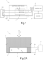
- an electrical safety device comprises a sensitive element 2 consisting of a first contact element 2a and a second contact element 2b electrically connected to a control unit 4, which is external to the electrical safety device 1 and coupled to a machinery or apparatus 5 (the control unit 4 can be integrated into the machinery or apparatus 5 or arranged externally thereto).
- the sensitive element 2 switches its operating state, in particular, the first contact element 2a, which is normally electrically separated from the second contact element 2b, electrically contacts the same second contact element 2b.
- the control unit 4 detects switching of the operating state of the sensitive element 2 and, in response to this switching, promptly interrupts or limits the operation of the coupled machinery or apparatus 5, so as to guarantee safety of the operator.
- the control unit 4 can be a controller dedicated to monitoring of the operating state of the electrical safety device 1, or it can be the controller (of the PLC - Programmable Logic Controller - type) of the same machinery or apparatus 5.
- each of the first and second contact elements 2a, 2b is part of a respective electrical circuit comprising the control unit 4 and a termination connector element 100.
- the first and second contact elements 2a, 2b are connected to a first and, respectively, to a second terminal (indicated by 'a' and 'b'), of the control unit 4 and of the termination connector element 100, interposed along a first and a second circuit branch;
- the aforementioned first circuit branch is part of a first electrical circuit which closes through a first return line 101 connected to a third terminal (indicated by 'c') of the control unit 4 and of the termination connector element 100
- the aforementioned second circuit branch is part of a second electrical circuit which closes through a second return line 102 connected to a fourth terminal (indicated by 'd') of the control unit 4 and of the termination connector element 100. Therefore, within the same termination connector element 100, the first terminal 'a' is connected to the third terminal 'c' and the second terminal 'b' is connected to the fourth terminal 'd'.
- the control unit 4 is configured to detect the correct connections and the electrical continuity of the first and second electrical circuits; for this purpose, the control unit 4 supplies terminal 'a' with a first control signal (for example, a so-called "triggered", pulsed or square-wave voltage signal), which must be detected as identical on terminal 'c' under correct operating conditions; and similarly it supplies the terminal 'b' with a second control signal (for example, again, a pulsed voltage signal) with different characteristics (for example in terms of frequency, duty cycle and/or amplitude) compared to the first control signal, which must be detected as identical on terminal 'd' under correct operating conditions.
- a first control signal for example, a so-called "triggered", pulsed or square-wave voltage signal
- a second control signal for example, again, a pulsed voltage signal
- control unit 4 If the control unit 4 does not detect the expected signal on terminal 'c' or on terminal 'd', it sets the machine 5 into an alarm state, as it detects a connection failure or a defect in the electrical safety device 1, in particular in its sensitive element 2. In particular, if the first and second contact elements 2a, 2b of the sensitive element 2 come into contact with each other, due to compression following contact interaction with the operator, the control unit 4 detects on terminals 'c' and 'd' a signal different from the first and second control signals individually provided on terminals 'a' and 'b' (in particular, a pulse signal resulting from the "combination" of the first and the second control signals), so that the same control unit 4 can detect switching of the operating state of the electrical safety device 1 and set the machine 5 into the alarm state and/or interrupt or limit its operation.
- the first and second contact elements 2a, 2b consist of a respective sheet or plate made of a conductive material, for example aluminium or copper, which are normally arranged at an appropriate separation distance and electrically connected to respective terminals.
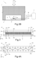
- Figure 2A shows a first embodiment of a known type of electrical safety device 1, in this case of the bumper type.
- This safety device 1 comprises a base structure 6; and a covering structure 7, for example made of polyurethane foam or other material, for example an elastomeric material, soft to the touch, optionally covered with a suitable material interfacing the external environment.
- a covering structure 7 for example made of polyurethane foam or other material, for example an elastomeric material, soft to the touch, optionally covered with a suitable material interfacing the external environment.
- the covering structure 7 is coupled above the base structure 6 and internally defines a hollow chamber 8 having a bottom wall defined by the same base structure 6.
- the conductive sheet of the first contact element 2a for example made of aluminium, is coupled, for example by gluing, to the base structure 6, at the bottom wall of the chamber 8; the respective conductive sheet of the second contact element 2b, for example also made of aluminium, is coupled to a top wall of the same chamber 8, so as to face the conductive sheet of the first contact element 2a and be electrically isolated and separated from the latter by an air gap having a height substantially equal to the height of the chamber 8 (in a vertical direction, orthogonal to the plane of extension of the conductive sheets).
- the first and second contact elements 2a, 2b are electrically connected, via respective electric wires 9a, 9b, to the respective terminals 'a' and 'b' of the control unit 4, which is arranged externally of the electrical safety device 1 (and, not shown, to the termination connector element 100).
- a contact pressure P (as shown schematically by the arrow in the aforementioned Figure 2A ) on the covering structure 7, at an external side thereof opposite the base structure 6, causes the two conductive sheets of the first and second contact elements 2a, 2b to come close together and subsequently contact each other, so as to cause their electrical contact, which is detected by the control unit 4 (for example in the manner previously described in detail).
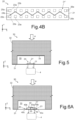
- Figure 2B shows a second embodiment, also of a known type, of an electrical safety device 1, again of the bumper type.
- the first and second contact elements 2a, 2b of the sensitive element 2 consist of respective plates of conductive material, for example copper, extending in a length direction and having a width smaller than the corresponding width of the chamber 8. These plates are arranged on the base structure 6, one on top of the other at a certain separation distance, which is determined by the presence of spacer elements 11 arranged at regular intervals along their length and made of a suitable dielectric material.
- the first and second contact elements 2a, 2b are arranged in the chamber 8 on a support 12 coupled to the base structure 6.
- the first and second contact elements 2a, 2b are electrically connected, via respective electric wires 9a, 9b, to the respective terminals, again indicated by 'a' and 'b', in turn connected to the control unit 4, which is arranged externally of the electrical safety device 1 (and to the termination connector element 100, not shown here).
- the plate of the second contact element 2b touches the plate of the first contact element 2a (arranged below), resulting in the closing of the electrical contact.
- WO 99/09570 A1 discloses a force-responsive sensor comprising upper and lower cover layers, the upper layer being resilient and flexible.
- An electrically conductive layer carries separate individual electrically insulating spacers which separate it from two electrically inductive members. Each of these members has a plurality of spaced resilient fingers, the fingers of the two members being inter-digitated.
- the members are formed as films on the layer. Where the members are not supported by the spacers, they are normally held apart from the conductive layer by the resilience of the upper layer. In response to an applied force, on or more of the fingers is pressed into contact with the conductive layer to enable the production of a corresponding electrical signal.
- GB 2 261 115 A discloses a pressure sensitive mat having two electrically conductive plates spaced apart by non conductive compressible separators. Located adjacent to the separators are electrically conductive elements, e.g. washers fixed to the lower plate or integral portions of at least one of the plates, which extend across a fraction of the gap between the plates. The plates are sealed at their edges by a sealing bead and a metal strip is placed adjacent the sealing bead. When pressure is applied to the mat above a separator, the top plate is deformed and the separator is compressed until the plate contacts the element completing an electrical circuit. When pressure is applied at the edge of the mat the top plate and sealing bead are deformed until the top plate contacts the metal strip completing an electrical circuit. When pressure is applied above the gap away from a separator, direct electrical contact is made between the plates.
- electrically conductive elements e.g. washers fixed to the lower plate or integral portions of at least one of the plates, which extend across a fraction of the gap between the plates.
- the object of the present invention is to provide a solution which allows the previously highlighted problems to be solved.
- an electrical safety device is provided, as defined in the appended claims.
- one aspect of the present solution comprises providing the sensitive element of a contact-sensitive electrical device by means of a Printed Circuit Board (PCB), on which both contact elements designed to electrically contact each other to switch the operating state of the electrical safety device are printed;
- the PCB can be provided in a rigid (for example, Fiberglass, CEM - Composite Epoxy Material, or the like) or flexible (for example, Mylar, Kapton, aluminum, copper or the like) support.
- Figure 3 shows a sensitive element 20 of an electrical device, in particular a contact-sensitive electrical safety device (not shown here).
- the sensitive element 20 comprises a (PCB) printed circuit base 21 defining a rigid or flexible support (as indicated above) and having a front face 21' on which a first contact arrangement 22a and a second contact arrangement 22b are provided by means of PCB printing techniques.
- PCB printed circuit base 21 defining a rigid or flexible support (as indicated above) and having a front face 21' on which a first contact arrangement 22a and a second contact arrangement 22b are provided by means of PCB printing techniques.
- the printed circuit base 21 has an elongated rectangular shape with greatest dimension in a first direction x of a horizontal plane xy and smallest dimension (much smaller than the greatest dimension) in a second direction y of the same horizontal plane xy, orthogonal to the first direction x.
- the first and second contact arrangements 22a, 22b are made of copper (or a similar conductive material, for example gold) and covered with graphite (gold or other conductive material which does not undergo changes in surface conductivity over time); in particular, the covering, for example of graphite, prevents oxidation of the contacts, thereby ensuring electrical continuity for a longer time.
- Each contact arrangement 22a, 22b comprises a plurality of conductive elements 23a, 23b provided on the front face 21' of the printed circuit base 21 and uniformly arranged and distributed along the extension of the printed circuit base 21 in the first direction x; in the example shown, the conductive elements 23a, 23b have an elongated shape, generally rectangular, along the second direction y.
- the conductive elements 23a of the first contact arrangement 22a are alternated with the conductive elements 23b of the second contact arrangement 22b along the extension of the printed circuit base 21 (along the first direction x), thus providing an overall interdigitated contact arrangement.
- Each contact arrangement 22a, 22b further comprises a respective electrical connection track 24a, 24b, which electrically connects the respective conductive elements 23a, 23b to each other and has a longitudinal extension along the first direction x; in the example, the electrical connection track 24a of the first contact arrangement 22a is arranged above the interdigitated pattern of the conductive elements 23a, 23b, whereas the electrical connection track 24b of the second contact arrangement 22b is arranged below the same interdigitated pattern of the conductive elements 23a, 23b (with respect to the second direction y).
- Each contact arrangement 22a, 22b further comprises a respective input terminal 25a, 25b, which is connected to the respective electrical connection track 24a, 24b and arranged at a first edge portion of the printed circuit base 21; and a respective output terminal 26a, 26b, which is connected to the respective electrical connection track 24a, 24b and arranged at a second edge portion of the printed circuit base 21, which is longitudinally opposite the first edge portion along the first direction x.
- input terminals 25a, 25b and output terminals 26a, 26b can be connected to the terminals (previously indicated by 'a' and 'b') of the control unit 4 (not shown here) arranged externally to the electrical safety device and designed to control the interruption or limitation of the operation of the associated machinery or apparatus 5 (also not shown here) and, respectively, of the termination connector element 100 (also not shown here).
- FIG. 27 Further electrical connection tracks, schematically indicated by 27, can also advantageously be provided on the same printed circuit base 21, for example to provide the first and second return lines 101, 102 connected to the third and fourth terminals ('c' and 'd') of the control unit 4 and of the termination connector element 100 (not shown here), to define the first and second electrical circuits.
- the printed circuit base 21 is of the one-sided or single-sided type, i.e. only printed on its front face 21'.
- the pressure due to impact of an operator on the electrical safety device causes a conductive actuator element (not shown here) to contact the front face 21' of the printed circuit base 21, at a contact area large enough to cause a short circuit between the first and the second contact arrangements 22a, 22b, and the associated switching of the operating state of the sensitive element 20 (for example, in the manner previously discussed with reference to Figure 1 ).
- the first and second contact arrangements 22a, 22b are again electrically separated (so that the electrical safety device is ready to detect a subsequent contact).
- Figures 4A and 4B show a different embodiment of the sensitive element 20 of the contact-sensitive electrical safety device, in this case, too, provided by means of a printed circuit base 21 (of the rigid or flexible type).
- the first and second contact arrangements 22a, 22b comprise a respective plurality of conductive elements 23a, 23b uniformly arranged and distributed along the main extension of the printed circuit base 21 (in the first direction x) and provided on the front face 21' of said printed circuit base 21 (as shown in Figure 4A ).
- these conductive elements 23a, 23b of the first and second contact arrangements 22a, 22b are aligned in two rows (along the first direction x), arranged above and below the printed circuit base 21 (relative to the second direction y).
- conductive elements 23a of the first contact arrangement 22a alternate with conductive elements 23b of the second contact arrangement 22b; furthermore, in the embodiment illustrated in Figure 4A , each conductive element 23a of the first contact arrangement 22a is aligned in the second direction y with a conductive element 23b of the second contact arrangement 22b).
- the electrical connection track 24a electrically connecting the conductive elements 23a of the first contact arrangement 22a to each other is provided on the front face 21' of the printed circuit base 21 (as shown in Figure 4A ); whereas the electrical connection track 24b electrically connecting the conductive elements 23b of the second contact arrangement 22b to each other is provided on a back face 21" of the same printed circuit base 21, opposite the aforesaid front face 21' (as shown in Figure 4B ).
- the printed circuit base 21 is of the double-sided type, i.e. printed both on its front face 21' and on its back face 21".
- Both of the aforementioned electrical connection tracks 24a, 24b extend along a line with a triangular or "sawtooth" shape, wherein each segment of the line connects together conductive elements 23a, 23b of the first and, respectively, second contact arrangements 22a, 22b, arranged consecutively along the first direction x and on opposite sides of the printed circuit base 21 relative to the second direction y.
- the electrical connection tracks 24a, 24b of the first and second contact arrangements 22a, 22b have a mirror pattern along the first direction x and are superimposed in the vertical direction (orthogonal to the horizontal plane xy).
- each contact arrangement 22a, 22b comprises the respective input terminal 25a, 25b and the respective output terminal 26a, 26b, in this case printed on the front face 21' of the printed circuit base 21.
- pressure due to contact of an operator with the electrical safety device causes a conductive actuator element (not shown here) to contact the front face 21' of the printed circuit base 21, at a contact area large enough to cause a short circuit between the first and the second contact arrangements 22a, 22b, and the associated switching of the operating state of the sensitive element 20.
- Figure 5 shows an embodiment of a contact-sensitive electrical safety device, here indicated by 30, for example of the bumper type, which embeds the sensitive element 20 discussed above and the respective printed circuit base 21 (it should be noted that the following discussion applies regardless of the embodiment of the sensitive element 20, i.e. both the embodiment discussed with reference to Figure 3 and the embodiment discussed with reference to Figures 4A and 4B ).
- the electrical safety device 30 comprises a base structure 31; and a covering structure 32, for example made of a polyurethane foam or other material, for example an elastomeric material, soft to the touch and optionally covered with a suitable material interfacing with the external environment, coupled above the base structure 31 and internally defining a hollow chamber 33 having a bottom wall at said base structure 31.
- a covering structure 32 for example made of a polyurethane foam or other material, for example an elastomeric material, soft to the touch and optionally covered with a suitable material interfacing with the external environment, coupled above the base structure 31 and internally defining a hollow chamber 33 having a bottom wall at said base structure 31.
- the printed circuit base 21 of the sensitive element 20 is coupled, for example by gluing, to the base structure 31, at the bottom wall of the chamber 33, with the front face 21' facing the same chamber 33.
- a suitable seat designed to house the printed circuit base 21 can be provided inside the base structure 31.
- a conductive actuator element 35 for example an aluminium sheet, is coupled to a top wall of the chamber 33, so as to face the front face 21' of the printed circuit base 21, from which it is normally separated by an air gap having a height substantially equal to the height of the chamber 33.
- FIG. 5 schematically shows respective terminals, again indicated by 'a' and 'b', which are electrically connected to the first and second contact arrangements 22a, 22b and can in turn be connected to the control unit 4, which is arranged externally to the electrical safety device 30 (as previously discussed).
- a contact pressure P (as shown schematically by the arrow in the aforementioned Figure 5 ) on the covering structure 32 causes the conductive actuator element 35 and the front face 21' of the printed circuit base 21 firstly to come close together and then to contact each other, thus causing, as previously described, electrical contact between the first and the second contact arrangements 22a, 22b, which can be detected by the control unit 4.
- the conductive actuator element 35 may also not be electrically and/or mechanically continuous in the longitudinal direction and, for example, may consist of a plurality of portions separately and individually coupled to the top wall of the chamber 33.
- a distinct conductive actuator element 35 may not be present, as the electrical contact between the first and the second contact arrangements 22a, 22b in response to the contact pressure P, is in this case provided by the same covering structure 32, which acts itself as the conductive actuator element.
- FIGS 6A and 6B illustrate a further embodiment of the contact-sensitive electrical safety device, again indicated by 30, in the example again of the bumper type, which embeds the sensitive element 20 and the related printed circuit base 21 (again, it should be noted that the following discussion applies regardless of the embodiment of the same sensitive element 20).
- This embodiment differs from the previous one in that it provides an actuation membrane 40 coupled to the front face 21' of the printed circuit base 21, for example made of a rubber or a suitable silicone material.
- the actuation membrane 40 comprises a central portion 40a arranged above and facing the first and second contact arrangements 22a, 22b printed on the front face 21' of the printed circuit base 21 (it should be noted that Figure 6B shows, purely by way of example, the interdigitated pattern of the first and second contact arrangements 22a, 22b); a separation gap is normally present between the central portion 40a of the actuation membrane 40 and the printed circuit base 21.
- This central portion 40a of the actuation membrane 40 carries, in a position facing the contact arrangements 22a, 22b, a conductive band 42 made of a suitable material, for example a conductive rubber.
- This conductive band 42 in the illustrated embodiment, has a longitudinal extension (in the first direction x) substantially corresponding to the extension of the printed circuit base 21 and a width extension along the second direction y smaller than the corresponding extension of the first and second contact arrangements 22a, 22b, being arranged centrally relative to the same contact arrangements 22a, 22b.
- the actuation membrane 40 further comprises side wall portions 40b, which are arranged laterally to the aforementioned central portion 40a, have elastic, springlike characteristics, and define the aforementioned separation gap between the central portion 40a of the actuation membrane 40 and the printed circuit base 21; and coupling portions 40c, which are arranged laterally to the side wall portions 40b and are coupled, for example by gluing, to the printed circuit base 21.
- the electrical safety device 30 comprises the base structure 31 and the covering structure 32 internally defining the hollow chamber 33; and the printed circuit base 21 of the sensitive element 20 is coupled to the base structure 31, at the bottom wall of the chamber 33, with the front face 21' facing the same chamber 33.
- the printed circuit base 21 and the coupled actuation membrane 40 make up a distinct, so-called “stand-alone” sensitive element, which is capable of switching its operating state in the presence of the contact pressure P due to contact, without the intervention of any external conductive element.
- the application of the contact pressure P on the covering structure 32 causes the covering structure 32 and the actuation membrane 40 firstly to come close together and then to contact each other. Consequently, the actuation membrane 40 deforms and the conductive band 42 carried by its central portion 40a comes into contact with the underlying contact arrangements 22a, 22b. Following actuation, the actuation membrane 40 then returns to the position at rest, with the separation gap between the aforementioned central portion 40a and the underlying printed circuit base 21.
- the central portion 40a of the actuation membrane 40 is made of a suitable conductive material, the aforementioned conductive band 42 may not be present, as, in this case, it is the same central portion 40a that acts as the conductive actuator element 35 of the electrical safety device 30.
- the conductive band 42 (or the same actuation membrane 40, if it is made of a conductive material) need not be electrically connected, thus only acting as a contact actuator element; furthermore, no continuity of the same conductive band 42 (or of the same actuation membrane 40) is required, which, in fact, can also consist of several separate and distinct portions.
- the advantages include the following:
- a further advantage of the described solution is that it allows modular construction; it is in fact possible to provide a plurality of printed circuit bases 21, each forming a single modular unit, in a single printed circuit board (PCB).
- PCB printed circuit board
- a plurality of printed circuit bases 21 can be provided in a single PCB 50, aligned with and coupled to one another in the first direction x, with a fixed interconnection pitch.
- the circuits provided by the respective contact arrangements 22a, 22b are connected in series, as the output terminals 26a, 26b of one printed circuit base 21 are connected to the input terminals 25a, 25b of a consecutive printed circuit base 21.
- the PCB 50 has structural weakening regions 52, for example provided by means of micro-holes defining a kind of cracking in the material of the same PCB 50.
- structural weakening regions 52 for example provided by means of micro-holes defining a kind of cracking in the material of the same PCB 50.
- modularity can be provided not only in the first direction x (forming "rows" of printed circuit bases 21), but, in a two-dimensional manner, also in the second direction y (forming "columns" of printed circuit bases 21), so as to cover a desired surface portion with the resulting electrical safety device 30.
- the structural weakening regions 52 are provided between consecutive printed circuit bases 21, not only along the first direction x, but also along the second direction y (extending along the entire width and the entire length of said printed circuit bases 21).
- suitable electrical connection elements are provided in this case for suitably connecting together the electrical connection tracks 24a, 24b of the various rows of printed circuit bases 21, so as to connect all the contact arrangements 22a, 22b to one another.
- the electrical safety device 30 can have several uses, for example in the industrial field, to interrupt or limit the operation of electrical machinery or devices.
- the electrical safety device 30 can be advantageously used in a machine for processing wood panels, for example of the type comprising an elongated base provided with longitudinal guide members parallel to a first, substantially horizontal direction; a plurality of cross members mounted between the longitudinal guide members parallel to a second, substantially horizontal direction transverse to the first direction; and at least one support block mounted on each cross member to hold at least one panel.
- the machine is also provided with an overhead crane, which is movable along the base in the first direction, extends above the base in the second direction, and normally supports a processing head equipped with a tool for removing panel chips.
- Each support block is positioned on the respective cross member according to the dimensions of the panels to be processed and is bounded by a substantially flat upper face which can be connected to a pneumatic suction device via a valve device operated by the same panels.
- the upper faces of the support blocks are coplanar with each other and define, as a whole, a substantially horizontal support surface suitable to support at least one panel to be processed.
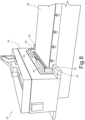
- Figure 8 schematically shows a possible embodiment of the aforementioned overhead crane, indicated here by 54, of the machine for processing wood panels, schematically indicated by 55.
- a plurality of electrical safety devices 30 are coupled to portions of the overhead crane 54 which, in use, can come into contact with an operator, for example, at side end portions and at a central opening, intended to be engaged by the aforementioned elongated base (here schematically shown and indicated by 56) of the machine 55.
- additional safety devices may also be coupled to the machine 55, in order to interrupt or at least limit the operation of the same machine 55 when an operator enters an area considered to be at risk.
- circuit elements can be advantageously provided in the printed circuit base 21 of the electrical safety device 30, for example additional electrical connection tracks, which could for example be required by safety regulations to ensure redundancy in the electrical connections between different electrical safety devices 30 (functionally connected in series) associated with the same machine or device.
- contact-sensitive electrical device described herein, mainly in the industrial field, but also in the civil field, for example, to interrupt the operation of industrial doors or electrically-closing doors, in the event of contact or impact with a user.
- the sensitive element 20 of the contact-sensitive electrical device can be embedded within a deformable structure 60, for example a gasket or sheath, to form, for example, a contact- or pressure-sensitive edge device.
- the printed circuit base 21 of the sensitive element 20 is coupled to an internal wall of the deformable structure 60, in a cavity 62 internally defined by the same deformable structure 60.
- the input terminals 25a, 25b and the output terminals 26a, 26b of the sensitive element 20 can suitably protrude from the deformable structure 60, to allow the electrical connection thereof.
- the input terminals 25a, 25b and output terminals 26a, 26b may remain inside the deformable structure 60, electrically connected with appropriate cables that carry the signals outside the same structure.
- the deformable structure 60 (of which Figure 9A shows a profile having a shape illustrated purely by way of example - this profile in fact can have any desired shape) can be completely or partially covered on the internal wall with a conductive material or, alternatively, be itself made of a suitable conductive material (for example, a rubber or silicone material made conductive by doping, or any other conductive material, for example a plastic material).
- a suitable conductive material for example, a rubber or silicone material made conductive by doping, or any other conductive material, for example a plastic material.
- a separation gap is normally present between the printed circuit base 21 (in particular its upper face 21') and a facing portion of the aforementioned internal wall of the deformable structure 60, so that in conditions at rest the sensitive element 20 remains isolated.
- the deformable structure 60 deforms elastically and its internal (conductive) wall comes into contact with the contact arrangements 22a, 22b of the sensitive element 20, thereby causing the short circuit between the same contact arrangements 22a, 22b. It should therefore be noted that, in this case, it is the same deformable structure 60 that acts as the conductive actuator element 35, suitable for defining the electrical contact between the first and the second contact arrangements 22a, 22b.
- the deformable structure 60 returns to its original shape, with the separation gap between the printed circuit base 21 and the internal wall.
Landscapes
- Engineering & Computer Science (AREA)
- General Engineering & Computer Science (AREA)
- Mechanical Engineering (AREA)
- Switch Cases, Indication, And Locking (AREA)
- Switches That Are Operated By Magnetic Or Electric Fields (AREA)
Claims (17)
- Elektronische Maschine oder Gerät (55) mit mindestens einer berührungsempfindlichen elektrischen Sicherheitsvorrichtung (30) und einer Steuereinheit (4), die elektrisch mit der berührungsempfindlichen elektrischen Sicherheitsvorrichtung (30) gekoppelt ist, wobei die berührungsempfindliche elektrische Sicherheitsvorrichtung (30) Folgendes umfasst:ein empfindliches Element (20); undein leitendes Betätigungselement (35), das so konfiguriert ist, dass es einen Betriebszustand des empfindlichen Elements (20) als Reaktion auf einen auf die elektrische Sicherheitsvorrichtung (30) wirkenden Kontakt schaltet,wobei das empfindliche Element (20) mindestens eine gedruckte Schaltungsbasis (21) umfasst, auf der eine erste und eine zweite Kontaktanordnung (22a, 22b) vorgesehen sind, die normalerweise elektrisch getrennt sind; wobei das leitende Betätigungselement (35) so konfiguriert ist, dass es als Reaktion auf den Kontakt einen elektrischen Kontakt zwischen der ersten und der zweiten Kontaktanordnung (22a, 22b) herstellt, dadurch gekennzeichnet, dass die Steuereinheit (4) so konfiguriert ist, dass sie den Betrieb der elektronischen Maschine oder des Geräts (55) unterbricht oder einschränkt, wenn ein Umschalten des Betriebszustands des empfindlichen Elements (20) erfasst wird.
- Elektronische Maschine oder Gerät nach Anspruch 1, wobei die gedruckte Schaltungsbasis (21) eine Vorderseite (21') aufweist und wobei jede der ersten und zweiten Kontaktanordnungen (22a, 22b) eine jeweilige Vielzahl von leitenden Elementen (23a, 23b), die auf der Vorderseite (21') vorgesehen sind, und auch eine jeweilige elektrische Verbindungsspur (24a, 24b) umfasst, die die leitenden Elemente (23a, 23b) der jeweiligen Vielzahl elektrisch miteinander verbindet; wobei das leitende Betätigungselement (35) so konfiguriert ist, dass es einen elektrischen Kontakt zwischen einer Anzahl von leitenden Elementen (23a) der ersten Kontaktanordnung (22a) und einer entsprechenden Anzahl von leitenden Elementen (23b) der zweiten Kontaktanordnung (22b) herstellt.
- Elektronische Maschine oder Gerät nach Anspruch 2, wobei die gedruckte Schaltungsbasis (21) eine Haupterstreckung in einer ersten Richtung (x) aufweist; und wobei die leitenden Elemente (23a, 23b) der ersten und zweiten Kontaktanordnung (22a, 22b) entlang der Haupterstreckungsrichtung (x) verteilt sind, wobei sich leitende Elemente (23a) der ersten Kontaktanordnung (22a) mit leitenden Elementen (23b) der zweiten Kontaktanordnung (22b) entlang der ersten Richtung (x) abwechseln.
- Elektronische Maschine oder Gerät nach Anspruch 3, wobei jede der ersten und zweiten Kontaktanordnungen (22a, 22b) ferner einen jeweiligen Eingangsanschluss (25a, 25b) umfasst, der mit der jeweiligen elektrischen Verbindungsspur (24a, 24b) verbunden und an einem ersten Randabschnitt der gedruckten Schaltungsbasis (21) angeordnet ist; und einen jeweiligen Ausgangsanschluss (26a, 26b), der mit der jeweiligen elektrischen Verbindungsspur (24a, 24b) verbunden ist und an einem zweiten Randabschnitt der gedruckten Schaltungsbasis (21) angeordnet ist, der in Längsrichtung gegenüber dem ersten Randabschnitt entlang der ersten Richtung (x) liegt.
- Elektronische Maschine oder Gerät nach Anspruch 3 oder 4, wobei die leitenden Elemente (23a, 23b) der ersten und zweiten Kontaktanordnungen (22a, 22b) eine längliche Form entlang einer zweiten Richtung (y) haben, die orthogonal zu der ersten Richtung (x) ist, und als Ganzes gemäß einem ineinandergreifenden Muster angeordnet sind; und wobei die elektrischen Verbindungsspuren (24a, 24b) der ersten und zweiten Kontaktanordnungen (22a, 22b) beide auf der Vorderseite (21') vorgesehen sind und eine Längserstreckung entlang der ersten Richtung (x) aufweisen, wobei die elektrische Verbindungsspur (24a) der ersten Kontaktanordnung (22a) auf einer oberen Seite und die elektrische Verbindungsspur (24b) der zweiten Kontaktanordnung (22b) auf einer unteren Seite des ineinandergreifenden Musters von leitenden Elementen (23a, 23b) relativ zu der zweiten Richtung (y) angeordnet ist
- Elektronische Maschine oder Gerät nach Anspruch 3 oder 4, wobei die gedruckte Schaltungsbasis (21) ferner eine Rückseite (21") gegenüber der Vorderseite (21') aufweist; und wobei die leitenden Elemente (23a, 23b) der ersten und zweiten Kontaktanordnung (22a, 22b) entlang der ersten Richtung (x) in zwei Reihen ausgerichtet sind, die auf einer Oberseite und einer Unterseite der gedruckten Schaltungsbasis (21) relativ zu der zweiten Richtung (y) angeordnet sind, wobei sich leitende Elemente (23a) der ersten Kontaktanordnung (22a) mit leitenden Elementen (23b) der zweiten Kontaktanordnung (22b) entlang jeder der Reihen abwechseln; und wobei die elektrische Verbindungsspur (24a), die die leitenden Elemente (23a) der ersten Kontaktanordnung (22a) elektrisch miteinander verbindet, auf der Vorderseite (21') der gedruckten Schaltungsbasis (21) vorgesehen ist und die elektrische Verbindungsspur (24b), die die leitenden Elemente (23b) der zweiten Kontaktanordnung (22b) elektrisch miteinander verbindet, auf der Rückseite (21") der gedruckten Schaltungsbasis (21) vorgesehen ist.
- Elektronische Maschine oder Gerät nach einem der vorhergehenden Ansprüche, wobei das empfindliche Element (20) eine modulare Konfiguration aufweist und eine PCB-Platte (50) umfasst, auf der mehrere gedruckte Schaltungsbasen (21) vorgesehen sind, die in einer ersten (x) und/oder zweiten (y) Richtung miteinander fluchten und miteinander gekoppelt sind; wobei die PCB-Platte (50) strukturelle Schwächungsbereiche (52) an den Kopplungsbereichen zwischen benachbarten gedruckten Schaltungsbasen (21) aufweist.
- Elektronische Maschine oder Gerät nach einem der vorhergehenden Ansprüche, ferner mit einer Basisstruktur (31) und einer Abdeckungsstruktur (32), die über der Basisstruktur (31) gekoppelt ist und im Inneren eine hohle Kammer (33) definiert, die eine Bodenwand an der Basisstruktur (31) aufweist und das empfindliche Element (20) aufnimmt; wobei die Basis (21) der gedruckten Schaltung auf der Basisstruktur (31) an der Bodenwand der Kammer (33) gekoppelt ist, wobei die Vorderseite (21') der Kammer (33) zugewandt ist
- Elektronische Maschine oder Gerät nach Anspruch 8, wobei das leitende Betätigungselement (35) mit einer oberen Wand der Kammer (33) verbunden ist, die der Vorderseite (21') der gedruckten Schaltungsbasis (21) zugewandt ist, von der es normalerweise durch einen Trennungsspalt getrennt ist.
- Elektronische Maschine oder Gerät nach einem der Ansprüche 1 bis 8, ferner mit einer Betätigungsmembran (40), die auf der Oberseite (21') der gedruckten Schaltungsbasis (21) angebracht ist und mit dieser in Kontakt steht; wobei die Betätigungsmembran (40) Folgendes aufweist: einen zentralen Abschnitt (40a), der oberhalb der ersten und der zweiten Kontaktanordnung (22a, 22b) angeordnet ist und diesen zugewandt ist; Seitenwandabschnitte (40b), die seitlich zum zentralen Abschnitt (40a) angeordnet sind und einen Trennspalt zwischen dem zentralen Abschnitt (40a) und der gedruckten Schaltungsbasis (21) definieren; und Kopplungsabschnitte (40c), die seitlich zu den Seitenwandabschnitten (40b) angeordnet sind und mit der gedruckten Schaltungsbasis (21) gekoppelt sind und mit dieser in Kontakt stehen.
- Elektronische Maschine oder Gerät nach Anspruch 10, wobei der zentrale Abschnitt (40a) der Betätigungsmembran (40) in einer den Kontaktanordnungen (22a, 22b) zugewandten Position ein leitfähiges Band (42) trägt; und wobei das leitfähige Band das leitfähige Betätigungselement (35) bildet.
- Elektronische Maschine oder Gerät nach Anspruch 10, wobei der zentrale Teil (40a) der Betätigungsmembran (40) aus einem leitfähigen Material besteht und das leitfähige Betätigungselement (35) bildet.
- Elektronische Maschine oder Gerät nach einem der Ansprüche 1-8, mit einer verformbaren Struktur (60), die innen einen Hohlraum (62) definiert, in dem das empfindliche Element (20) untergebracht ist; wobei die gedruckte Schaltungsbasis (21) des empfindlichen Elements (20) mit einer Innenwand der verformbaren Struktur (60) innerhalb des Hohlraums (62) in einem Trennungsabstand von der Innenwand in einem Ruhezustand verbunden ist; wobei die verformbare Struktur (60) vollständig oder teilweise an der Innenwand mit einem leitfähigen Material bedeckt ist oder alternativ selbst aus einem leitfähigen Material hergestellt ist und so konfiguriert ist, dass sie die gedruckte Schaltungsbasis (21) durch Kompression aufgrund eines Kontaktdrucks (P) kontaktiert.
- Elektronische Maschine oder Gerät nach einem der vorhergehenden Ansprüche, wobei die erste und die zweite Kontaktanordnung (2 2a, 22b) aus einem leitfähigen Material bestehen, das mit Graphit, Gold oder einem anderen leitfähigen Material beschichtet ist, das im Laufe der Zeit keine Änderungen der Oberflächenleitfähigkeit erfährt.
- Elektronische Maschine oder Gerät nach einem der vorhergehenden Ansprüche, wobei mindestens eine elektrische Leiterbahn (27) auf der gedruckten Schaltungsbasis (21) vorgesehen ist, die so ausgelegt ist, dass sie mit der ersten oder zweiten Kontaktanordnung (22a, 22b) ein und denselben Stromkreis bildet.
- Elektronische Maschine oder Gerät nach einem der vorhergehenden Ansprüche zum Bearbeiten von Bauteilen aus Holz oder dergleichen, umfassend: eine längliche Basis (56), die zum Tragen der Bauteile aus Holz oder dergleichen ausgelegt ist; und einen Brückenkran (54), der sich quer über die längliche Basis (56) erstreckt und relativ zu dieser beweglich ist und einen Bearbeitungskopf zum Bearbeiten der Bauteile aus Holz oder dergleichen trägt; wobei die mindestens eine elektrische Sicherheitsvorrichtung (30) mit dem Brückenkran (54) gekoppelt ist.
- Elektronische Maschine oder Gerät nach einem der vorhergehenden Ansprüche, wobei die elektrische Sicherheitseinrichtung (30) eine Stoßfängereinrichtung oder eine empfindliche Kanteneinrichtung ist.
Applications Claiming Priority (1)
| Application Number | Priority Date | Filing Date | Title |
|---|---|---|---|
| IT102018000020308A IT201800020308A1 (it) | 2018-12-20 | 2018-12-20 | Dispositivo elettrico di sicurezza sensibile al contatto avente un elemento sensibile perfezionato |
Publications (2)
| Publication Number | Publication Date |
|---|---|
| EP3671005A1 EP3671005A1 (de) | 2020-06-24 |
| EP3671005B1 true EP3671005B1 (de) | 2023-10-18 |
Family
ID=66049465
Family Applications (1)
| Application Number | Title | Priority Date | Filing Date |
|---|---|---|---|
| EP19218892.8A Active EP3671005B1 (de) | 2018-12-20 | 2019-12-20 | Kontakt-empfindliches elektrisches sicherheitsgerät mit einem verbesserten empfindlichen element |
Country Status (2)
| Country | Link |
|---|---|
| EP (1) | EP3671005B1 (de) |
| IT (1) | IT201800020308A1 (de) |
Family Cites Families (4)
| Publication number | Priority date | Publication date | Assignee | Title |
|---|---|---|---|---|
| GB2261115A (en) * | 1991-10-29 | 1993-05-05 | Eja Eng Plc | Pressure sensitive mat |
| US5667152A (en) * | 1995-05-30 | 1997-09-16 | Mooring; Jonathan E. | Safety system for a wood chipper |
| CA2296365A1 (en) * | 1997-08-14 | 1999-02-25 | Draftex Industries Limited | Force-responsive detectors and systems |
| DE19829019A1 (de) * | 1998-06-30 | 2000-01-05 | Poettinger Gmbh Geb | Hackmaschine |
-
2018
- 2018-12-20 IT IT102018000020308A patent/IT201800020308A1/it unknown
-
2019
- 2019-12-20 EP EP19218892.8A patent/EP3671005B1/de active Active
Also Published As
| Publication number | Publication date |
|---|---|
| EP3671005A1 (de) | 2020-06-24 |
| IT201800020308A1 (it) | 2020-06-20 |
Similar Documents
| Publication | Publication Date | Title |
|---|---|---|
| EP1327997B1 (de) | Elastische Folienstruktur mit verbesserter elektrischer Kontinuitätsfunktion, und Leiterplattenstruktur | |
| US4829404A (en) | Method of producing a flexible circuit and master grid therefor | |
| US7829813B2 (en) | Touch sensor switch | |
| CN101098138A (zh) | 电气/电子设备的电容式开关 | |
| WO2008096639A1 (ja) | タッチスイッチ構造 | |
| EP3030874A1 (de) | Montageanordnung für eine piezoelektrische sensorvorrichtung | |
| EP3671005A1 (de) | Berührungsempfindliche elektrische sicherheitsvorrichtung mit einem verbesserten empfindlichen element | |
| CN103066452A (zh) | 连接器 | |
| US7919903B2 (en) | MEMS switch | |
| US7746662B2 (en) | Touch panel | |
| JP4386767B2 (ja) | 高分子アクチュエータを用いた電気素子 | |
| US12117354B2 (en) | Capacitance detection sensor, capacitance detection sensor module and state determination method using capacitance detection sensor | |
| CN1266535A (zh) | 力敏检测器和系统 | |
| TWI579879B (zh) | switch | |
| CN201781473U (zh) | 用于按键的电路开关 | |
| US9095058B2 (en) | Electrode structure with spatial interpolation for capacitive touch panel | |
| JPH0319148Y2 (de) | ||
| KR20110008433A (ko) | 저항막 방식 터치패널 | |
| CN108733242B (zh) | 金属引线触控面板及其制作方法 | |
| CN109155213A (zh) | 开关体 | |
| CN217467636U (zh) | 触控显示面板及触控显示装置 | |
| EP3550411B1 (de) | Berührungssensor zur verhinderung von falscherkennung und elektronische vorrichtung damit | |
| CN218996020U (zh) | 一种触控面板及电容屏 | |
| US8963056B2 (en) | Planar electrode system | |
| JPH09282973A (ja) | フィルムタッチパネル装置 |
Legal Events
| Date | Code | Title | Description |
|---|---|---|---|
| PUAI | Public reference made under article 153(3) epc to a published international application that has entered the european phase |
Free format text: ORIGINAL CODE: 0009012 |
|
| STAA | Information on the status of an ep patent application or granted ep patent |
Free format text: STATUS: THE APPLICATION HAS BEEN PUBLISHED |
|
| AK | Designated contracting states |
Kind code of ref document: A1 Designated state(s): AL AT BE BG CH CY CZ DE DK EE ES FI FR GB GR HR HU IE IS IT LI LT LU LV MC MK MT NL NO PL PT RO RS SE SI SK SM TR |
|
| AX | Request for extension of the european patent |
Extension state: BA ME |
|
| STAA | Information on the status of an ep patent application or granted ep patent |
Free format text: STATUS: REQUEST FOR EXAMINATION WAS MADE |
|
| 17P | Request for examination filed |
Effective date: 20201222 |
|
| RBV | Designated contracting states (corrected) |
Designated state(s): AL AT BE BG CH CY CZ DE DK EE ES FI FR GB GR HR HU IE IS IT LI LT LU LV MC MK MT NL NO PL PT RO RS SE SI SK SM TR |
|
| RAP1 | Party data changed (applicant data changed or rights of an application transferred) |
Owner name: BIESSE S.P.A. |
|
| GRAP | Despatch of communication of intention to grant a patent |
Free format text: ORIGINAL CODE: EPIDOSNIGR1 |
|
| STAA | Information on the status of an ep patent application or granted ep patent |
Free format text: STATUS: GRANT OF PATENT IS INTENDED |
|
| INTG | Intention to grant announced |
Effective date: 20230511 |
|
| GRAS | Grant fee paid |
Free format text: ORIGINAL CODE: EPIDOSNIGR3 |
|
| GRAA | (expected) grant |
Free format text: ORIGINAL CODE: 0009210 |
|
| STAA | Information on the status of an ep patent application or granted ep patent |
Free format text: STATUS: THE PATENT HAS BEEN GRANTED |
|
| AK | Designated contracting states |
Kind code of ref document: B1 Designated state(s): AL AT BE BG CH CY CZ DE DK EE ES FI FR GB GR HR HU IE IS IT LI LT LU LV MC MK MT NL NO PL PT RO RS SE SI SK SM TR |
|
| REG | Reference to a national code |
Ref country code: GB Ref legal event code: FG4D |
|
| REG | Reference to a national code |
Ref country code: CH Ref legal event code: EP |
|
| REG | Reference to a national code |
Ref country code: DE Ref legal event code: R096 Ref document number: 602019039519 Country of ref document: DE |
|
| REG | Reference to a national code |
Ref country code: IE Ref legal event code: FG4D |
|
| REG | Reference to a national code |
Ref country code: LT Ref legal event code: MG9D |
|
| REG | Reference to a national code |
Ref country code: NL Ref legal event code: MP Effective date: 20231018 |
|
| REG | Reference to a national code |
Ref country code: AT Ref legal event code: MK05 Ref document number: 1622754 Country of ref document: AT Kind code of ref document: T Effective date: 20231018 |
|
| PG25 | Lapsed in a contracting state [announced via postgrant information from national office to epo] |
Ref country code: NL Free format text: LAPSE BECAUSE OF FAILURE TO SUBMIT A TRANSLATION OF THE DESCRIPTION OR TO PAY THE FEE WITHIN THE PRESCRIBED TIME-LIMIT Effective date: 20231018 |
|
| PG25 | Lapsed in a contracting state [announced via postgrant information from national office to epo] |
Ref country code: GR Free format text: LAPSE BECAUSE OF FAILURE TO SUBMIT A TRANSLATION OF THE DESCRIPTION OR TO PAY THE FEE WITHIN THE PRESCRIBED TIME-LIMIT Effective date: 20240119 |
|
| PG25 | Lapsed in a contracting state [announced via postgrant information from national office to epo] |
Ref country code: IS Free format text: LAPSE BECAUSE OF FAILURE TO SUBMIT A TRANSLATION OF THE DESCRIPTION OR TO PAY THE FEE WITHIN THE PRESCRIBED TIME-LIMIT Effective date: 20240218 |
|
| PG25 | Lapsed in a contracting state [announced via postgrant information from national office to epo] |
Ref country code: LT Free format text: LAPSE BECAUSE OF FAILURE TO SUBMIT A TRANSLATION OF THE DESCRIPTION OR TO PAY THE FEE WITHIN THE PRESCRIBED TIME-LIMIT Effective date: 20231018 |
|
| PG25 | Lapsed in a contracting state [announced via postgrant information from national office to epo] |
Ref country code: AT Free format text: LAPSE BECAUSE OF FAILURE TO SUBMIT A TRANSLATION OF THE DESCRIPTION OR TO PAY THE FEE WITHIN THE PRESCRIBED TIME-LIMIT Effective date: 20231018 |
|
| PG25 | Lapsed in a contracting state [announced via postgrant information from national office to epo] |
Ref country code: ES Free format text: LAPSE BECAUSE OF FAILURE TO SUBMIT A TRANSLATION OF THE DESCRIPTION OR TO PAY THE FEE WITHIN THE PRESCRIBED TIME-LIMIT Effective date: 20231018 |
|
| PG25 | Lapsed in a contracting state [announced via postgrant information from national office to epo] |
Ref country code: LT Free format text: LAPSE BECAUSE OF FAILURE TO SUBMIT A TRANSLATION OF THE DESCRIPTION OR TO PAY THE FEE WITHIN THE PRESCRIBED TIME-LIMIT Effective date: 20231018 Ref country code: IS Free format text: LAPSE BECAUSE OF FAILURE TO SUBMIT A TRANSLATION OF THE DESCRIPTION OR TO PAY THE FEE WITHIN THE PRESCRIBED TIME-LIMIT Effective date: 20240218 Ref country code: GR Free format text: LAPSE BECAUSE OF FAILURE TO SUBMIT A TRANSLATION OF THE DESCRIPTION OR TO PAY THE FEE WITHIN THE PRESCRIBED TIME-LIMIT Effective date: 20240119 Ref country code: ES Free format text: LAPSE BECAUSE OF FAILURE TO SUBMIT A TRANSLATION OF THE DESCRIPTION OR TO PAY THE FEE WITHIN THE PRESCRIBED TIME-LIMIT Effective date: 20231018 Ref country code: BG Free format text: LAPSE BECAUSE OF FAILURE TO SUBMIT A TRANSLATION OF THE DESCRIPTION OR TO PAY THE FEE WITHIN THE PRESCRIBED TIME-LIMIT Effective date: 20240118 Ref country code: AT Free format text: LAPSE BECAUSE OF FAILURE TO SUBMIT A TRANSLATION OF THE DESCRIPTION OR TO PAY THE FEE WITHIN THE PRESCRIBED TIME-LIMIT Effective date: 20231018 Ref country code: PT Free format text: LAPSE BECAUSE OF FAILURE TO SUBMIT A TRANSLATION OF THE DESCRIPTION OR TO PAY THE FEE WITHIN THE PRESCRIBED TIME-LIMIT Effective date: 20240219 |
|
| PG25 | Lapsed in a contracting state [announced via postgrant information from national office to epo] |
Ref country code: SE Free format text: LAPSE BECAUSE OF FAILURE TO SUBMIT A TRANSLATION OF THE DESCRIPTION OR TO PAY THE FEE WITHIN THE PRESCRIBED TIME-LIMIT Effective date: 20231018 Ref country code: RS Free format text: LAPSE BECAUSE OF FAILURE TO SUBMIT A TRANSLATION OF THE DESCRIPTION OR TO PAY THE FEE WITHIN THE PRESCRIBED TIME-LIMIT Effective date: 20231018 Ref country code: PL Free format text: LAPSE BECAUSE OF FAILURE TO SUBMIT A TRANSLATION OF THE DESCRIPTION OR TO PAY THE FEE WITHIN THE PRESCRIBED TIME-LIMIT Effective date: 20231018 Ref country code: NO Free format text: LAPSE BECAUSE OF FAILURE TO SUBMIT A TRANSLATION OF THE DESCRIPTION OR TO PAY THE FEE WITHIN THE PRESCRIBED TIME-LIMIT Effective date: 20240118 Ref country code: LV Free format text: LAPSE BECAUSE OF FAILURE TO SUBMIT A TRANSLATION OF THE DESCRIPTION OR TO PAY THE FEE WITHIN THE PRESCRIBED TIME-LIMIT Effective date: 20231018 Ref country code: HR Free format text: LAPSE BECAUSE OF FAILURE TO SUBMIT A TRANSLATION OF THE DESCRIPTION OR TO PAY THE FEE WITHIN THE PRESCRIBED TIME-LIMIT Effective date: 20231018 |
|
| PG25 | Lapsed in a contracting state [announced via postgrant information from national office to epo] |
Ref country code: DK Free format text: LAPSE BECAUSE OF FAILURE TO SUBMIT A TRANSLATION OF THE DESCRIPTION OR TO PAY THE FEE WITHIN THE PRESCRIBED TIME-LIMIT Effective date: 20231018 |
|
| REG | Reference to a national code |
Ref country code: DE Ref legal event code: R097 Ref document number: 602019039519 Country of ref document: DE |
|
| PG25 | Lapsed in a contracting state [announced via postgrant information from national office to epo] |
Ref country code: CZ Free format text: LAPSE BECAUSE OF FAILURE TO SUBMIT A TRANSLATION OF THE DESCRIPTION OR TO PAY THE FEE WITHIN THE PRESCRIBED TIME-LIMIT Effective date: 20231018 |
|
| PG25 | Lapsed in a contracting state [announced via postgrant information from national office to epo] |
Ref country code: SK Free format text: LAPSE BECAUSE OF FAILURE TO SUBMIT A TRANSLATION OF THE DESCRIPTION OR TO PAY THE FEE WITHIN THE PRESCRIBED TIME-LIMIT Effective date: 20231018 |
|
| PG25 | Lapsed in a contracting state [announced via postgrant information from national office to epo] |
Ref country code: SM Free format text: LAPSE BECAUSE OF FAILURE TO SUBMIT A TRANSLATION OF THE DESCRIPTION OR TO PAY THE FEE WITHIN THE PRESCRIBED TIME-LIMIT Effective date: 20231018 Ref country code: SK Free format text: LAPSE BECAUSE OF FAILURE TO SUBMIT A TRANSLATION OF THE DESCRIPTION OR TO PAY THE FEE WITHIN THE PRESCRIBED TIME-LIMIT Effective date: 20231018 Ref country code: RO Free format text: LAPSE BECAUSE OF FAILURE TO SUBMIT A TRANSLATION OF THE DESCRIPTION OR TO PAY THE FEE WITHIN THE PRESCRIBED TIME-LIMIT Effective date: 20231018 Ref country code: EE Free format text: LAPSE BECAUSE OF FAILURE TO SUBMIT A TRANSLATION OF THE DESCRIPTION OR TO PAY THE FEE WITHIN THE PRESCRIBED TIME-LIMIT Effective date: 20231018 Ref country code: DK Free format text: LAPSE BECAUSE OF FAILURE TO SUBMIT A TRANSLATION OF THE DESCRIPTION OR TO PAY THE FEE WITHIN THE PRESCRIBED TIME-LIMIT Effective date: 20231018 Ref country code: CZ Free format text: LAPSE BECAUSE OF FAILURE TO SUBMIT A TRANSLATION OF THE DESCRIPTION OR TO PAY THE FEE WITHIN THE PRESCRIBED TIME-LIMIT Effective date: 20231018 |
|
| REG | Reference to a national code |
Ref country code: CH Ref legal event code: PL |
|
| PLBE | No opposition filed within time limit |
Free format text: ORIGINAL CODE: 0009261 |
|
| STAA | Information on the status of an ep patent application or granted ep patent |
Free format text: STATUS: NO OPPOSITION FILED WITHIN TIME LIMIT |
|
| PG25 | Lapsed in a contracting state [announced via postgrant information from national office to epo] |
Ref country code: LU Free format text: LAPSE BECAUSE OF NON-PAYMENT OF DUE FEES Effective date: 20231220 |
|
| PG25 | Lapsed in a contracting state [announced via postgrant information from national office to epo] |
Ref country code: MC Free format text: LAPSE BECAUSE OF FAILURE TO SUBMIT A TRANSLATION OF THE DESCRIPTION OR TO PAY THE FEE WITHIN THE PRESCRIBED TIME-LIMIT Effective date: 20231018 |
|
| REG | Reference to a national code |
Ref country code: BE Ref legal event code: MM Effective date: 20231231 |
|
| PG25 | Lapsed in a contracting state [announced via postgrant information from national office to epo] |
Ref country code: MC Free format text: LAPSE BECAUSE OF FAILURE TO SUBMIT A TRANSLATION OF THE DESCRIPTION OR TO PAY THE FEE WITHIN THE PRESCRIBED TIME-LIMIT Effective date: 20231018 Ref country code: LU Free format text: LAPSE BECAUSE OF NON-PAYMENT OF DUE FEES Effective date: 20231220 |
|
| 26N | No opposition filed |
Effective date: 20240719 |
|
| GBPC | Gb: european patent ceased through non-payment of renewal fee |
Effective date: 20240118 |
|
| REG | Reference to a national code |
Ref country code: IE Ref legal event code: MM4A |
|
| PG25 | Lapsed in a contracting state [announced via postgrant information from national office to epo] |
Ref country code: IE Free format text: LAPSE BECAUSE OF NON-PAYMENT OF DUE FEES Effective date: 20231220 |
|
| PG25 | Lapsed in a contracting state [announced via postgrant information from national office to epo] |
Ref country code: GB Free format text: LAPSE BECAUSE OF NON-PAYMENT OF DUE FEES Effective date: 20240118 |
|
| PG25 | Lapsed in a contracting state [announced via postgrant information from national office to epo] |
Ref country code: BE Free format text: LAPSE BECAUSE OF NON-PAYMENT OF DUE FEES Effective date: 20231231 |
|
| PG25 | Lapsed in a contracting state [announced via postgrant information from national office to epo] |
Ref country code: FR Free format text: LAPSE BECAUSE OF NON-PAYMENT OF DUE FEES Effective date: 20231231 |
|
| PG25 | Lapsed in a contracting state [announced via postgrant information from national office to epo] |
Ref country code: CH Free format text: LAPSE BECAUSE OF NON-PAYMENT OF DUE FEES Effective date: 20231231 |
|
| PG25 | Lapsed in a contracting state [announced via postgrant information from national office to epo] |
Ref country code: SI Free format text: LAPSE BECAUSE OF FAILURE TO SUBMIT A TRANSLATION OF THE DESCRIPTION OR TO PAY THE FEE WITHIN THE PRESCRIBED TIME-LIMIT Effective date: 20231018 |
|
| PG25 | Lapsed in a contracting state [announced via postgrant information from national office to epo] |
Ref country code: SI Free format text: LAPSE BECAUSE OF FAILURE TO SUBMIT A TRANSLATION OF THE DESCRIPTION OR TO PAY THE FEE WITHIN THE PRESCRIBED TIME-LIMIT Effective date: 20231018 Ref country code: IE Free format text: LAPSE BECAUSE OF NON-PAYMENT OF DUE FEES Effective date: 20231220 Ref country code: GB Free format text: LAPSE BECAUSE OF NON-PAYMENT OF DUE FEES Effective date: 20240118 Ref country code: FR Free format text: LAPSE BECAUSE OF NON-PAYMENT OF DUE FEES Effective date: 20231231 Ref country code: CH Free format text: LAPSE BECAUSE OF NON-PAYMENT OF DUE FEES Effective date: 20231231 Ref country code: BE Free format text: LAPSE BECAUSE OF NON-PAYMENT OF DUE FEES Effective date: 20231231 |
|
| PG25 | Lapsed in a contracting state [announced via postgrant information from national office to epo] |
Ref country code: FI Free format text: LAPSE BECAUSE OF FAILURE TO SUBMIT A TRANSLATION OF THE DESCRIPTION OR TO PAY THE FEE WITHIN THE PRESCRIBED TIME-LIMIT Effective date: 20231019 |
|
| PG25 | Lapsed in a contracting state [announced via postgrant information from national office to epo] |
Ref country code: CY Free format text: LAPSE BECAUSE OF FAILURE TO SUBMIT A TRANSLATION OF THE DESCRIPTION OR TO PAY THE FEE WITHIN THE PRESCRIBED TIME-LIMIT; INVALID AB INITIO Effective date: 20191220 |
|
| PG25 | Lapsed in a contracting state [announced via postgrant information from national office to epo] |
Ref country code: HU Free format text: LAPSE BECAUSE OF FAILURE TO SUBMIT A TRANSLATION OF THE DESCRIPTION OR TO PAY THE FEE WITHIN THE PRESCRIBED TIME-LIMIT; INVALID AB INITIO Effective date: 20191220 |
|
| PG25 | Lapsed in a contracting state [announced via postgrant information from national office to epo] |
Ref country code: TR Free format text: LAPSE BECAUSE OF FAILURE TO SUBMIT A TRANSLATION OF THE DESCRIPTION OR TO PAY THE FEE WITHIN THE PRESCRIBED TIME-LIMIT Effective date: 20231018 |
|
| PGFP | Annual fee paid to national office [announced via postgrant information from national office to epo] |
Ref country code: IT Payment date: 20251117 Year of fee payment: 7 |
|
| PGFP | Annual fee paid to national office [announced via postgrant information from national office to epo] |
Ref country code: DE Payment date: 20251229 Year of fee payment: 7 |