EP3670987A1 - High pressure hose - Google Patents
High pressure hose Download PDFInfo
- Publication number
- EP3670987A1 EP3670987A1 EP18846513.2A EP18846513A EP3670987A1 EP 3670987 A1 EP3670987 A1 EP 3670987A1 EP 18846513 A EP18846513 A EP 18846513A EP 3670987 A1 EP3670987 A1 EP 3670987A1
- Authority
- EP
- European Patent Office
- Prior art keywords
- steel
- wound
- steel cord
- high pressure
- layer
- Prior art date
- Legal status (The legal status is an assumption and is not a legal conclusion. Google has not performed a legal analysis and makes no representation as to the accuracy of the status listed.)
- Withdrawn
Links
- 229910000831 Steel Inorganic materials 0.000 claims abstract description 256
- 239000010959 steel Substances 0.000 claims abstract description 256
- 230000003014 reinforcing effect Effects 0.000 claims abstract description 77
- 229920001971 elastomer Polymers 0.000 description 43
- 239000005060 rubber Substances 0.000 description 43
- 238000004804 winding Methods 0.000 description 8
- 238000009954 braiding Methods 0.000 description 7
- 239000000126 substance Substances 0.000 description 5
- 238000013459 approach Methods 0.000 description 4
- 239000000463 material Substances 0.000 description 4
- 238000000034 method Methods 0.000 description 4
- 229920001084 poly(chloroprene) Polymers 0.000 description 4
- 230000000052 comparative effect Effects 0.000 description 3
- 229920001577 copolymer Polymers 0.000 description 3
- 239000000945 filler Substances 0.000 description 3
- 239000012779 reinforcing material Substances 0.000 description 3
- KUDUQBURMYMBIJ-UHFFFAOYSA-N 2-prop-2-enoyloxyethyl prop-2-enoate Chemical compound C=CC(=O)OCCOC(=O)C=C KUDUQBURMYMBIJ-UHFFFAOYSA-N 0.000 description 2
- VTYYLEPIZMXCLO-UHFFFAOYSA-L Calcium carbonate Chemical compound [Ca+2].[O-]C([O-])=O VTYYLEPIZMXCLO-UHFFFAOYSA-L 0.000 description 2
- 229920002943 EPDM rubber Polymers 0.000 description 2
- YCKRFDGAMUMZLT-UHFFFAOYSA-N Fluorine atom Chemical compound [F] YCKRFDGAMUMZLT-UHFFFAOYSA-N 0.000 description 2
- 244000043261 Hevea brasiliensis Species 0.000 description 2
- 239000005062 Polybutadiene Substances 0.000 description 2
- VYPSYNLAJGMNEJ-UHFFFAOYSA-N Silicium dioxide Chemical compound O=[Si]=O VYPSYNLAJGMNEJ-UHFFFAOYSA-N 0.000 description 2
- XLOMVQKBTHCTTD-UHFFFAOYSA-N Zinc monoxide Chemical compound [Zn]=O XLOMVQKBTHCTTD-UHFFFAOYSA-N 0.000 description 2
- 229920000800 acrylic rubber Polymers 0.000 description 2
- 229920005549 butyl rubber Polymers 0.000 description 2
- 238000013329 compounding Methods 0.000 description 2
- 230000000694 effects Effects 0.000 description 2
- 239000005038 ethylene vinyl acetate Substances 0.000 description 2
- 239000000835 fiber Substances 0.000 description 2
- 239000011737 fluorine Substances 0.000 description 2
- 229910052731 fluorine Inorganic materials 0.000 description 2
- 239000010720 hydraulic oil Substances 0.000 description 2
- 229920002681 hypalon Polymers 0.000 description 2
- 229920003049 isoprene rubber Polymers 0.000 description 2
- 239000000203 mixture Substances 0.000 description 2
- 229920003052 natural elastomer Polymers 0.000 description 2
- 229920001194 natural rubber Polymers 0.000 description 2
- 229920001200 poly(ethylene-vinyl acetate) Polymers 0.000 description 2
- 229920000058 polyacrylate Polymers 0.000 description 2
- 229920002857 polybutadiene Polymers 0.000 description 2
- 229920000139 polyethylene terephthalate Polymers 0.000 description 2
- 239000005020 polyethylene terephthalate Substances 0.000 description 2
- 238000002407 reforming Methods 0.000 description 2
- 229920002379 silicone rubber Polymers 0.000 description 2
- 239000004945 silicone rubber Substances 0.000 description 2
- 229920003048 styrene butadiene rubber Polymers 0.000 description 2
- 238000004073 vulcanization Methods 0.000 description 2
- VHOQXEIFYTTXJU-UHFFFAOYSA-N Isobutylene-isoprene copolymer Chemical compound CC(C)=C.CC(=C)C=C VHOQXEIFYTTXJU-UHFFFAOYSA-N 0.000 description 1
- 239000004677 Nylon Substances 0.000 description 1
- CBENFWSGALASAD-UHFFFAOYSA-N Ozone Chemical compound [O-][O+]=O CBENFWSGALASAD-UHFFFAOYSA-N 0.000 description 1
- 235000021355 Stearic acid Nutrition 0.000 description 1
- 239000002174 Styrene-butadiene Substances 0.000 description 1
- NINIDFKCEFEMDL-UHFFFAOYSA-N Sulfur Chemical compound [S] NINIDFKCEFEMDL-UHFFFAOYSA-N 0.000 description 1
- 229920006311 Urethane elastomer Polymers 0.000 description 1
- 229920002978 Vinylon Polymers 0.000 description 1
- 239000000654 additive Substances 0.000 description 1
- 230000000996 additive effect Effects 0.000 description 1
- 239000003963 antioxidant agent Substances 0.000 description 1
- 230000003078 antioxidant effect Effects 0.000 description 1
- 229910000019 calcium carbonate Inorganic materials 0.000 description 1
- 239000006229 carbon black Substances 0.000 description 1
- 230000015556 catabolic process Effects 0.000 description 1
- 239000003795 chemical substances by application Substances 0.000 description 1
- 239000004927 clay Substances 0.000 description 1
- 229910052570 clay Inorganic materials 0.000 description 1
- 239000012141 concentrate Substances 0.000 description 1
- 238000007796 conventional method Methods 0.000 description 1
- 238000006731 degradation reaction Methods 0.000 description 1
- 230000006866 deterioration Effects 0.000 description 1
- AFZSMODLJJCVPP-UHFFFAOYSA-N dibenzothiazol-2-yl disulfide Chemical compound C1=CC=C2SC(SSC=3SC4=CC=CC=C4N=3)=NC2=C1 AFZSMODLJJCVPP-UHFFFAOYSA-N 0.000 description 1
- 238000009826 distribution Methods 0.000 description 1
- 238000001125 extrusion Methods 0.000 description 1
- 239000012530 fluid Substances 0.000 description 1
- 239000003112 inhibitor Substances 0.000 description 1
- 239000011256 inorganic filler Substances 0.000 description 1
- 229910003475 inorganic filler Inorganic materials 0.000 description 1
- 238000004519 manufacturing process Methods 0.000 description 1
- 238000000465 moulding Methods 0.000 description 1
- DEQZTKGFXNUBJL-UHFFFAOYSA-N n-(1,3-benzothiazol-2-ylsulfanyl)cyclohexanamine Chemical compound C1CCCCC1NSC1=NC2=CC=CC=C2S1 DEQZTKGFXNUBJL-UHFFFAOYSA-N 0.000 description 1
- 229920001778 nylon Polymers 0.000 description 1
- QIQXTHQIDYTFRH-UHFFFAOYSA-N octadecanoic acid Chemical compound CCCCCCCCCCCCCCCCCC(O)=O QIQXTHQIDYTFRH-UHFFFAOYSA-N 0.000 description 1
- OQCDKBAXFALNLD-UHFFFAOYSA-N octadecanoic acid Natural products CCCCCCCC(C)CCCCCCCCC(O)=O OQCDKBAXFALNLD-UHFFFAOYSA-N 0.000 description 1
- 239000003921 oil Substances 0.000 description 1
- 150000002978 peroxides Chemical class 0.000 description 1
- 239000004014 plasticizer Substances 0.000 description 1
- -1 polyethylene terephthalate Polymers 0.000 description 1
- 238000010058 rubber compounding Methods 0.000 description 1
- 239000000377 silicon dioxide Substances 0.000 description 1
- 239000008117 stearic acid Substances 0.000 description 1
- 229910052717 sulfur Inorganic materials 0.000 description 1
- 239000011593 sulfur Substances 0.000 description 1
- 239000000454 talc Substances 0.000 description 1
- 229910052623 talc Inorganic materials 0.000 description 1
- 229920005992 thermoplastic resin Polymers 0.000 description 1
- 238000005491 wire drawing Methods 0.000 description 1
- 239000011787 zinc oxide Substances 0.000 description 1
Images


Classifications
-
- F—MECHANICAL ENGINEERING; LIGHTING; HEATING; WEAPONS; BLASTING
- F16—ENGINEERING ELEMENTS AND UNITS; GENERAL MEASURES FOR PRODUCING AND MAINTAINING EFFECTIVE FUNCTIONING OF MACHINES OR INSTALLATIONS; THERMAL INSULATION IN GENERAL
- F16L—PIPES; JOINTS OR FITTINGS FOR PIPES; SUPPORTS FOR PIPES, CABLES OR PROTECTIVE TUBING; MEANS FOR THERMAL INSULATION IN GENERAL
- F16L11/00—Hoses, i.e. flexible pipes
- F16L11/04—Hoses, i.e. flexible pipes made of rubber or flexible plastics
- F16L11/08—Hoses, i.e. flexible pipes made of rubber or flexible plastics with reinforcements embedded in the wall
- F16L11/085—Hoses, i.e. flexible pipes made of rubber or flexible plastics with reinforcements embedded in the wall comprising one or more braided layers
-
- F—MECHANICAL ENGINEERING; LIGHTING; HEATING; WEAPONS; BLASTING
- F16—ENGINEERING ELEMENTS AND UNITS; GENERAL MEASURES FOR PRODUCING AND MAINTAINING EFFECTIVE FUNCTIONING OF MACHINES OR INSTALLATIONS; THERMAL INSULATION IN GENERAL
- F16L—PIPES; JOINTS OR FITTINGS FOR PIPES; SUPPORTS FOR PIPES, CABLES OR PROTECTIVE TUBING; MEANS FOR THERMAL INSULATION IN GENERAL
- F16L11/00—Hoses, i.e. flexible pipes
- F16L11/04—Hoses, i.e. flexible pipes made of rubber or flexible plastics
- F16L11/08—Hoses, i.e. flexible pipes made of rubber or flexible plastics with reinforcements embedded in the wall
- F16L11/081—Hoses, i.e. flexible pipes made of rubber or flexible plastics with reinforcements embedded in the wall comprising one or more layers of a helically wound cord or wire
- F16L11/083—Hoses, i.e. flexible pipes made of rubber or flexible plastics with reinforcements embedded in the wall comprising one or more layers of a helically wound cord or wire three or more layers
-
- F—MECHANICAL ENGINEERING; LIGHTING; HEATING; WEAPONS; BLASTING
- F16—ENGINEERING ELEMENTS AND UNITS; GENERAL MEASURES FOR PRODUCING AND MAINTAINING EFFECTIVE FUNCTIONING OF MACHINES OR INSTALLATIONS; THERMAL INSULATION IN GENERAL
- F16L—PIPES; JOINTS OR FITTINGS FOR PIPES; SUPPORTS FOR PIPES, CABLES OR PROTECTIVE TUBING; MEANS FOR THERMAL INSULATION IN GENERAL
- F16L11/00—Hoses, i.e. flexible pipes
- F16L11/04—Hoses, i.e. flexible pipes made of rubber or flexible plastics
- F16L11/08—Hoses, i.e. flexible pipes made of rubber or flexible plastics with reinforcements embedded in the wall
Definitions
- the present invention relates to a high pressure hose, and particularly, to a high pressure hose including a reinforcing layer having a braided structure excellent in durability.
- a high pressure hose reinforced with a steel filament is used for a high pressure hose such as a hydraulic pump to withstand high pressure hydraulic oil.
- a high pressure hose such as a hydraulic pump to withstand high pressure hydraulic oil.
- the spiral structure refers to a structure in which a steel filament or the like is spirally wound around an inner layer tube
- the braided structure refers to a structure in which a steel filament or the like is braided and wound around an inner layer tube.
- Patent Document 1 JP5969163B2
- a reinforcing layer having a spiral structure is applied as a reinforcing layer.
- a high pressure hose including a reinforcing layer having a spiral structure has a problem that the hose has high rigidity and is difficult to handle.
- a high pressure hose including a reinforcing layer having a braided structure has an advantage that such a hose is easier to handle than a high pressure hose including a reinforcing layer having a spiral structure. For this reason, there is a demand for a high pressure hose including a reinforcing layer having a braided structure that can withstand high pressure.
- an object of the present invention is to provide a high pressure hose including a reinforcing layer having a braided structure that is excellent in durability.
- the present inventor intensively studied to find the following. Namely, in a high pressure hose including a reinforcing layer having a braided structure, when the wire diameter of a steel filament is increased in such a manner to withstand high pressure, the flexural rigidity increases and the braiding workability deteriorates, resulting in deterioration of a product thereof. On the other hand, when a steel cord obtained by twisting thin steel filaments was used, an expected performance was not obtained in terms of durability.
- the present inventor then observed an endurance fracture state of a high pressure hose including a reinforcing layer having a braided structure obtained by braiding a steel cord, and found that breakage occurs from a point where steel filaments intersect. In particular, since there was a deep rubbing trace in a portion where steel filaments constituting the steel cord intersected at a substantially right angle, it was found that this portion is the starting point of breakage. Based on this finding, the present inventor further intensively studied to find that the durability of a high pressure hose can be improved by optimizing the crossing angle between steel filaments at a portion where the steel filaments cross, thereby completing the present invention.
- the high pressure hose of the present invention is a high pressure hose including at least one reinforcing layer having a braided structure in which a steel cord formed by twisting a plurality of steel filaments is braided, wherein a crossing angle ⁇ between an outermost layer steel filament of an S-wound steel cord and an outermost layer steel filament of a Z-wound steel cord of a reinforcing layer having a braided structure on an innermost in a hose radial direction of the reinforcing layer having a braided structure is 76° or less.
- S-wound is a winding method in which a steel cord runs from an upper left to a lower right when the high pressure hose is viewed from a side with an axial direction vertical
- Z-wound is a winding method in which a steel cord runs from an upper right to a lower left.
- a twist angle of a steel filament with respect to a cord axis in the S-wound steel cord and the Z-wound steel cord is preferably from 2.8 to 10.5°.
- the crossing angle ⁇ is preferably 76° or less in all the reinforcing layers of a braided structure.
- the ⁇ o and the ⁇ i are preferably 108° or more.
- a high pressure hose including a reinforcing layer having a braided structure excellent in durability can be obtained.
- FIG. 1 is a cross-sectional perspective view of a high pressure hose according to a preferred embodiment of the present invention.
- the high pressure hose 10 of the present invention is a high pressure hose including at least one reinforcing layer 11 having a braided structure in which a steel cord formed by twisting a plurality of steel filaments is braided.
- a tubular inner rubber layer 12 is formed in the innermost layer and a tubular outer rubber layer 13 is formed in the outermost layer, and a reinforcing layer 11 having a braided structure is arranged between the inner rubber layer 12 and the outer rubber layer 13.
- the reinforcing layer 11 having a braided structure is composed of one layer, a plurality of layers may be layered via an intermediate rubber layer, or only a plurality of the reinforcing layers 11 having a braided structure may be layered continuously.
- the reinforcing layer having a braided structure is composed of preferably 3 layers or less, and more preferably 2 layers or less.
- the high pressure hose 10 of the present invention may include a reinforcing layer using a cord other than a steel cord, such as a steel filament single wire or an organic fiber cord.
- the hose may have a reinforcing layer made of an organic fiber cord such as vinylon, nylon, or polyethylene terephthalate (PET) on the inner side in the hose radial direction than the reinforcing layer 11 having a braided structure.
- a reinforcing layer made of an organic fiber cord such as vinylon, nylon, or polyethylene terephthalate (PET) on the inner side in the hose radial direction than the reinforcing layer 11 having a braided structure.
- PET polyethylene terephthalate
- a crossing angle ⁇ between an outermost layer steel filament of an S-wound steel cord and an outermost layer steel filament of a Z-wound steel cord of the reinforcing layer 11 having a braided structure composed of at least one layer on the innermost side in the hose radial direction of the reinforcing layer 11 having a braided structure is 76° or less, and preferably 72° or less.
- FIG. 2 is an explanatory view showing an example of a crossing angle of an outermost steel filament of a steel cord braided in a reinforcing layer of a braided structure
- FIG. 3 is an explanatory view showing another example of the crossing angle of an outermost steel filament of a steel cord braided in a reinforcing layer of a braided structure.
- the near side is the outside in the hose radial direction and the far side is the inside in the hose radial direction
- the near side is the outside in the hose radial direction and the far side is the inside in the hose radial direction.
- FIG. 3 the near side is the outside in the hose radial direction and the far side is the inside in the hose radial direction.
- a steel cord 20a is Z-wound and S-twisted
- a steel cord 20b is S-wound and S-twisted
- a steel cord 120a is Z-wound and S-twisted
- a steel cord 120b is S-wound and S-twisted.
- Arrows A, A', B, and B' in the figures indicate the twist direction of a steel filament that constitutes each steel cord.
- steel filaments are in contact with each other on the near side in the steel cords 20a and 120b on the far side, and on the far side in the steel cords 20b and 120a on the near side. Therefore, in FIGs.
- the twisting direction of the steel filament on the far side is represented by a broken line.
- the S-twist is a twist in which a steel filament runs from the upper left to the lower right when a steel cord is viewed from the side with the axial direction vertical.
- the Z twist is a twist in which a steel filament runs from the upper right to the lower left.
- the fatigue durability of the high pressure hose 10 can be improved by reducing the crossing angle ⁇ between an outermost steel filament of an S-wound steel cord and an outermost steel filament of a Z-wound steel cord.
- the reinforcing layer 11 having a braided structure in which a steel cord formed by twisting a plurality of steel filaments is used as a reinforcing material
- the reinforcing layer 11 having a braided structure is obtained by braiding an S-wound steel cord and a Z-wound steel cord, these are alternately on the outer side in the hose radial direction or on the inner side in the hose radial direction.
- a steel cord is obtained by twisting a steel filament, it is necessary to consider the twist angle of the steel filament.
- the twist angle of the outermost steel filament with respect to the cord axis direction of a steel cord is assumed to be 7°, which is a very common angle used in a tire or the like.
- the Z-wound steel cord is wound in the direction of 54.7° to the right with respect to the hose axis.
- the S-wound steel cord is wound in the direction of 54.7° to the left with respect to the hose axis.
- the crossing angle ⁇ between an outermost layer steel filament of a steel cord constituting the reinforcing layer 11 having a braided structure and the durability of a high pressure hose was studied, and when the crossing angle ⁇ was 76° or less, the durability of a high pressure hose was considerably improved. Therefore, in the high pressure hose 10 of the present invention, the crossing angle ⁇ between an outermost layer steel filament of S-wound steel cord and an outermost layer steel filament of Z-wound steel cord of the reinforcing layer 11 having a braided structure on the innermost in the hose radial direction of the reinforcing layer 11 having a braided structure is set to 76° or less.
- the crossing angle ⁇ is preferably 76° or less not only in the reinforcing layer 11 having a braided structure on the innermost in the hose radial direction of the reinforcing layers 11 having a braided structure but also in all reinforcing layers having a braided structure.
- Examples of the method of adjusting the crossing angle ⁇ between an outermost layer steel filament of an S-wound steel cord constituting the reinforcing layer 11 having a braided structure and an outermost layer steel filament of a Z-wound steel cord in the high pressure hose 10 of the present invention to 76° or less include appropriately designing the winding angle of these steel cords or the twist pitch of the steel filament.
- the twisting direction of the outermost layer steel filament of the S-wound steel cord and the twisting direction of the outermost layer steel filament of the Z-wound steel cord may be different from each other.
- the crossing angle ⁇ is 70.6°.
- the twist angle of the steel filament with respect to the cord axis of the S-wound steel cord and the Z-wound steel cord of the reinforcing layer 11 having a braided structure is preferably from 2.8 to 10.5°.
- the twist angle of a steel filament is 2.8° or more, the twist pitch is not too long, and it is possible to prevent a steel cord from being scattered during manufacture of a high pressure hose, which is preferable in view of molding workability.
- the strength of a high pressure hose can be favorably obtained by setting the twist angle of a steel filament to 10.5° or less.
- the twist angle of a steel filament is more preferably from 3.2° to 9°, still more preferably from 3° to 8°, and particularly preferably from 3.5° to 7°.
- the structure of a steel cord constituting the reinforcing layer 11 having a braided structure is not particularly limited.
- a so-called compact structure in which all layers are twisted in the same direction and the same pitch may be used.
- m, p, and q which show the twist structure of a steel cord are any integers in the above range.
- all or a part of the steel filaments constituting a cord may be reformed into a spiral, a polygon, a corrugated shape, or the like.
- the polygonal reforming include a reforming described in WO 1995/016816 .
- FIG. 4 shows a cross-sectional view of a steel cord according to a high pressure hose of a preferred embodiment of the present invention.
- a steel cord 20 in which steel filaments are twisted together has unevenness on the surface due to twists.
- a reinforcing layer 11 having a braided structure obtained by braiding such a steel cord 20 when convex portions generated by the twists contact with each other, stress is concentrated repeatedly between the convex portions on the surface of the steel cord 20, and the fatigue resistance is deteriorated. Such a problem becomes noticeable as the convex portion is sharper.
- the ⁇ o and the ⁇ i are preferably 108° or more.
- each steel filament constituting the steel cord is in the same layer.
- ⁇ o and ⁇ i are preferably obtuse angles, and ⁇ o and ⁇ i are preferably 120° or more, and more preferably 128° or more.
- the crossing angle ⁇ between an outermost layer steel filament of an S-wound steel cord and an outermost layer steel filament of an Z-wound steel cord of the reinforcing layer 11 having a braided structure in the innermost hose radial direction is 76° or less, and other specific structures and materials are not particularly limited.
- the steel cords when braiding steel cords, the steel cords may be braided one by one, or a plurality of steel cords may be bundled and braided.
- the wire diameter is preferably from 0.12 to 0.40 mm.
- the winding angle of a steel cord in the reinforcing layer 11 having a braided structure is preferably from 50 to 60°.
- the wire diameter is 0.12 mm or more, the wire drawing productivity of a steel filament is excellent, and when the wire diameter is 0.40 mm or less, the strength per cross-sectional area can be sufficiently secured, and the flexural rigidity proportional to the fourth power of the diameter can be kept sufficiently low.
- the winding angle of a steel cord is 50° or more, change in the hose diameter when pressure is applied to the hose can be reduced, and when the angle is less than 60°, change in hose length when pressure is applied to the hose can be reduced.
- rubber used for the high pressure hose 10 is not particularly limited, and the material of the inner rubber layer 12 can be appropriately selected based on the physical and chemical properties of a substance transported in the high pressure hose 10.
- Specific examples thereof include ethylene-propylene copolymer rubber (EPM), ethylene-propylene-diene terpolymer rubber (EPDM), acrylic rubber (ACM), ethylene acrylate rubber (AEM), chloroprene rubber (CR), chlorosulfonated polyethylene rubber, hydrin rubber, styrene-butadiene copolymer rubber (SBR), acrylonitrile-butadiene copolymer rubber (NBR), isobutylene-isoprene copolymer rubber (butyl rubber, IIR), natural rubber (NR), isoprene rubber (IR), butadiene rubber (BR), urethane rubber, silicone rubber, fluorine rubber, ethylene-vinyl acetate copolymer (EVA), and hydrogenated NBR.
- acrylic rubber (ACM), ethylene acrylate rubber (AEM), chloroprene rubber (CR), chlorosulfonated polyethylene rubber, hydrin rubber, acrylonitrile-butadiene copolymer rubber (NBR), hydrogenated NBR, silicone rubber, or fluorine rubber is preferable.
- ACM acrylic rubber
- AEM ethylene acrylate rubber
- CR chloroprene rubber
- NBR acrylonitrile-butadiene copolymer rubber
- hydrogenated NBR silicone rubber
- fluorine rubber fluorine rubber
- a known rubber compounding chemical and rubber filler generally used in the rubber industry can be used in consideration of material strength, durability, extrusion moldability, and the like.
- compounding chemicals and fillers include an inorganic filler such as carbon black, silica, calcium carbonate, talc, or clay; a plasticizer, a softener; a vulcanizing agent such as sulfur or a peroxide; a vulcanization aid such as zinc oxide or stearic acid; a vulcanization accelerator such as dibenzothiazyl disulfide, N -cyclohexyl-2-benzothiazyl-sulfenamide, or N -oxydiethylene-benzothiazyl-sulfenamide; and an additive such as an antioxidant or an ozone degradation inhibitor.
- These compounding chemicals and fillers may be used singly or in combination of two or more kinds thereof.
- the thickness of the inner rubber layer 12 varies depending on the type of material constituting the inner rubber layer 12, and is in the range of from 1 to 10 mm, and preferably in the range of from 1 to 6 mm.
- the inner diameter of the high pressure hose is selected according to a purpose, and is usually preferably in the range of from 3 mm to 200 mm.
- the outer rubber layer 13 can be made of a thermoplastic resin or the like, and may be made of various rubbers similar to the inner rubber layer 12.
- a steel cord constituting the reinforcing layer 11 is protected, damage to the reinforcing layer 11 can be prevented, and the appearance is also preferable.
- the thickness of the outer rubber layer 13 is in the range of from 1 mm to 20 mm.
- an intermediate rubber layer can be formed of various rubbers similar to the inner rubber layer 12.
- the high pressure hose of the present invention can be produced according to a conventional method, and is particularly useful as a high pressure hose used for transporting various high pressure fluids or a high pressure hose used to pump a hydraulic pump hydraulic oil to a working portion.
- a high pressure hose including a reinforcing layer having a braided structure was produced.
- a high pressure hose including one reinforcing layer having a braided structure a high pressure hose of a type shown in FIG. 1 was prepared, and in the case of a high pressure hose including two layers of reinforcing layers having a braided structure, a type in which two reinforcing layers having a braided structure were layered via an intermediate rubber layer was prepared.
- the winding angles of an S-wound steel cord and a Z-wound steel cord were 54.7°, respectively.
- Each of the obtained high pressure hoses was evaluated for impact durability according to the following procedure.
- Tables 1 to 3 show that the high pressure hose of the present invention has excellent impact durability.
Landscapes
- Engineering & Computer Science (AREA)
- General Engineering & Computer Science (AREA)
- Mechanical Engineering (AREA)
- Rigid Pipes And Flexible Pipes (AREA)
Abstract
Description
- The present invention relates to a high pressure hose, and particularly, to a high pressure hose including a reinforcing layer having a braided structure excellent in durability.
- In general, a high pressure hose reinforced with a steel filament is used for a high pressure hose such as a hydraulic pump to withstand high pressure hydraulic oil. There are two types of reinforcing structures for such high pressure hoses, a spiral structure and a braided structure. The spiral structure refers to a structure in which a steel filament or the like is spirally wound around an inner layer tube, and the braided structure refers to a structure in which a steel filament or the like is braided and wound around an inner layer tube.
- For example, Patent Document 1 proposes a rubber hose including a reinforcing layer formed by spirally winding a steel cord or a reinforcing layer formed by braiding a steel cord between an inner rubber layer and an outer rubber layer, wherein the steel cord has a 1×N structure (N = from 2 to 4) in which a plurality of steel braids that are not reformed are twisted together, the twist pitch of a steel filament with respect to the outer diameter of the steel cord is set within a predetermined range.
- Patent Document 1:
JP5969163B2 - In general, in a hose with a large diameter that requires high pressure resistance, a reinforcing layer having a spiral structure is applied as a reinforcing layer. A high pressure hose including a reinforcing layer having a spiral structure, however, has a problem that the hose has high rigidity and is difficult to handle. In contrast, a high pressure hose including a reinforcing layer having a braided structure has an advantage that such a hose is easier to handle than a high pressure hose including a reinforcing layer having a spiral structure. For this reason, there is a demand for a high pressure hose including a reinforcing layer having a braided structure that can withstand high pressure.
- Accordingly, an object of the present invention is to provide a high pressure hose including a reinforcing layer having a braided structure that is excellent in durability.
- In order to solve the above-described problem, the present inventor intensively studied to find the following. Namely, in a high pressure hose including a reinforcing layer having a braided structure, when the wire diameter of a steel filament is increased in such a manner to withstand high pressure, the flexural rigidity increases and the braiding workability deteriorates, resulting in deterioration of a product thereof. On the other hand, when a steel cord obtained by twisting thin steel filaments was used, an expected performance was not obtained in terms of durability.
- The present inventor then observed an endurance fracture state of a high pressure hose including a reinforcing layer having a braided structure obtained by braiding a steel cord, and found that breakage occurs from a point where steel filaments intersect. In particular, since there was a deep rubbing trace in a portion where steel filaments constituting the steel cord intersected at a substantially right angle, it was found that this portion is the starting point of breakage. Based on this finding, the present inventor further intensively studied to find that the durability of a high pressure hose can be improved by optimizing the crossing angle between steel filaments at a portion where the steel filaments cross, thereby completing the present invention.
- Specifically, the high pressure hose of the present invention is a high pressure hose including at least one reinforcing layer having a braided structure in which a steel cord formed by twisting a plurality of steel filaments is braided, wherein
a crossing angle θ between an outermost layer steel filament of an S-wound steel cord and an outermost layer steel filament of a Z-wound steel cord of a reinforcing layer having a braided structure on an innermost in a hose radial direction of the reinforcing layer having a braided structure is 76° or less. Here, S-wound is a winding method in which a steel cord runs from an upper left to a lower right when the high pressure hose is viewed from a side with an axial direction vertical, and Z-wound is a winding method in which a steel cord runs from an upper right to a lower left. - In the high pressure hose of the present invention, a twist angle of a steel filament with respect to a cord axis in the S-wound steel cord and the Z-wound steel cord is preferably from 2.8 to 10.5°. In the high pressure hose of the present invention, the crossing angle θ is preferably 76° or less in all the reinforcing layers of a braided structure. Further, in the high pressure hose of the present invention, in a cross section perpendicular to the cord axis of each steel cord constituting the reinforcing layer having a braided structure,
when an angle formed by connecting a center point of a steel filament located at an outermost in the hose radial direction and center points of both adjacent steel filaments located in the same layer as the steel filament is θo, and
when an angle formed by connecting a center point of a steel filament located at an innermost in the hose radial direction and center points of both adjacent steel filaments located in the same layer as the steel filament is θi,
the θo and the θi are preferably 108° or more. - According to the present invention, a high pressure hose including a reinforcing layer having a braided structure excellent in durability can be obtained.
-
-
FIG. 1 is a cross-sectional perspective view of a high pressure hose according to a preferred embodiment of the present invention. -
FIG. 2 is an explanatory view showing an example of a crossing angle of an outermost steel filament of a steel cord braided in a reinforcing layer of a braided structure. -
FIG. 3 is an explanatory view showing another example of the crossing angle of an outermost steel filament of a steel cord braided in a reinforcing layer of a braided structure. -
FIG. 4 is a cross-sectional view of a steel cord of a high pressure hose according to a preferred embodiment of the present invention. - Hereinafter, a high pressure hose of the present invention will be described in detail with reference to the drawings.
-
FIG. 1 is a cross-sectional perspective view of a high pressure hose according to a preferred embodiment of the present invention. Thehigh pressure hose 10 of the present invention is a high pressure hose including at least one reinforcinglayer 11 having a braided structure in which a steel cord formed by twisting a plurality of steel filaments is braided. In the illustratedhigh pressure hose 10, a tubularinner rubber layer 12 is formed in the innermost layer and a tubularouter rubber layer 13 is formed in the outermost layer, and a reinforcinglayer 11 having a braided structure is arranged between theinner rubber layer 12 and theouter rubber layer 13. Although in the illustrated example, the reinforcinglayer 11 having a braided structure is composed of one layer, a plurality of layers may be layered via an intermediate rubber layer, or only a plurality of the reinforcinglayers 11 having a braided structure may be layered continuously. In the high pressure hose of the present invention, the reinforcing layer having a braided structure is composed of preferably 3 layers or less, and more preferably 2 layers or less. Thehigh pressure hose 10 of the present invention may include a reinforcing layer using a cord other than a steel cord, such as a steel filament single wire or an organic fiber cord. For example, the hose may have a reinforcing layer made of an organic fiber cord such as vinylon, nylon, or polyethylene terephthalate (PET) on the inner side in the hose radial direction than the reinforcinglayer 11 having a braided structure. - In the
high pressure hose 10 according to the present invention, a crossing angle θ between an outermost layer steel filament of an S-wound steel cord and an outermost layer steel filament of a Z-wound steel cord of the reinforcinglayer 11 having a braided structure composed of at least one layer on the innermost side in the hose radial direction of the reinforcinglayer 11 having a braided structure is 76° or less, and preferably 72° or less. By satisfying such a relationship, it is possible to improve the durability of thehigh pressure hose 10 including the reinforcinglayer 11 having a braided structure. -
FIG. 2 is an explanatory view showing an example of a crossing angle of an outermost steel filament of a steel cord braided in a reinforcing layer of a braided structure, andFIG. 3 is an explanatory view showing another example of the crossing angle of an outermost steel filament of a steel cord braided in a reinforcing layer of a braided structure. Here, inFIG. 2 , the near side is the outside in the hose radial direction and the far side is the inside in the hose radial direction, and inFIG. 3 , the near side is the outside in the hose radial direction and the far side is the inside in the hose radial direction. InFIG. 2 , asteel cord 20a is Z-wound and S-twisted, and asteel cord 20b is S-wound and S-twisted. InFIG. 3 , asteel cord 120a is Z-wound and S-twisted, and asteel cord 120b is S-wound and S-twisted. Arrows A, A', B, and B' in the figures indicate the twist direction of a steel filament that constitutes each steel cord. Here, inFIGs. 2 and3 , steel filaments are in contact with each other on the near side in thesteel cords steel cords FIGs. 2 and3 , for thesteel cords - When pressure is applied to a high pressure hose including the braided reinforcing
layer 11 obtained by braiding a steel cord, a greater stress is applied to the steel cord toward the inner side in the hose radial direction. Therefore, the contact pressure between steel cords of the reinforcinglayer 11 having a braided structure increases due to a repeatedly applied pressure. This contact point is a portion where a repeated stress becomes maximum, fatigue fracture occurs starting from the vicinity thereof, and eventually, thehigh pressure hose 10 can no longer hold pressure and reaches the end of its life. At this time, with respect to contact between steel cords, when the crossing angle θ between steel filaments in the outermost layer of a steel cord approaches 90°, or, as shown inFIG. 2 , when the angle between steel cords approaches perpendicular, stress concentrates in a narrow region (point contact), and fatigue durability deteriorates. Conversely, when the crossing angle θ approaches 0°, or, as shown inFIG. 3 , when steel filaments approach each other in parallel, the stress is dispersed (line contact), and fatigue durability is improved. - Therefore, in the reinforcing
layer 11 having a braided structure of at least one reinforcinglayer 11 having a braided structure located on the innermost side in the hose radial direction, to which the greatest stress is applied, the fatigue durability of thehigh pressure hose 10 can be improved by reducing the crossing angle θ between an outermost steel filament of an S-wound steel cord and an outermost steel filament of a Z-wound steel cord. - The winding angle of a reinforcing material in the reinforcing
layer 11 having a braided structure is preferably around 54.7° with respect to the hose axis because the distribution of force in the hose longitudinal direction and the radial direction can be made uniform. Therefore, when a steel filament single wire that is not twisted is used as a reinforcing material for the reinforcinglayer 11 having a braided structure, the crossing angle θ of an S-wound steel filament and a Z-wound steel filament is 54.7 + 54.7 = 109.4°, that is, the crossing angle θ is 70.6°. However, in the high pressure hose including the reinforcinglayer 11 having a braided structure in which a steel cord formed by twisting a plurality of steel filaments is used as a reinforcing material, since the reinforcinglayer 11 having a braided structure is obtained by braiding an S-wound steel cord and a Z-wound steel cord, these are alternately on the outer side in the hose radial direction or on the inner side in the hose radial direction. Since a steel cord is obtained by twisting a steel filament, it is necessary to consider the twist angle of the steel filament. Here, the twist angle of the outermost steel filament with respect to the cord axis direction of a steel cord is assumed to be 7°, which is a very common angle used in a tire or the like. - Taking
FIG. 2 as an example, the Z-wound steel cord is wound in the direction of 54.7° to the right with respect to the hose axis. The twist angle of the outermost layer the S-twisted steel filament in contact with the S-wound steel cord in the hose radial direction is 7° to the left with respect to the cord axis. Therefore, the outermost steel filament of the Z-wound steel cord is 54.7 - 7 = 47.7° to the right with respect to the hose axis. On the other hand, the S-wound steel cord is wound in the direction of 54.7° to the left with respect to the hose axis, and an S-twisted steel filament of the outermost layer in contact with the Z-wound steel cord has a twist angle of 7° to the right with respect to the cord axis, and therefore, 54.7 - 7 = 47.7° to the left with respect to the hose axis. As a result, the outermost layer steel filament of the S-wound steel cord and the outermost layer steel filament of the Z-wound steel cord cross at 47.7 + 47.7 = 95.4°, or at a crossing angle θ of 84.6°, which is a severe angle close to a right angle. - Next, taking
FIG. 3 as an example, the Z-wound steel cord is wound in the direction of 54.7° to the right with respect to the hose axis, and the twist angle inside the hose radial direction of the outermost S-twisted steel filament in contact with the S-wound steel cord is 7° to the right with respect to the cord axis. Therefore, the outermost steel filament of the Z-wound steel cord is 54.7 + 7 = 61.7° to the right with respect to the hose axis. On the other hand, the S-wound steel cord is wound in the direction of 54.7° to the left with respect to the hose axis. The twist angle of the outermost layer S-twisted steel filament in contact with the Z-wound steel cord in the hose radial direction is 7° to the left with respect to the cord axis. Therefore, the outermost steel filament of the S-wound steel cord is 54.7 + 7 = 61.7° to the left with respect to the hose axis. As a result, a steel filament of the Z-wound steel cord and a steel filament of the S-wound steel cord cross at an angle of 61.7 + 61.7 = 123.4 °, or a crossing angle θ of 56.6°. - As described above, the relationship between the crossing angle θ between an outermost layer steel filament of a steel cord constituting the reinforcing
layer 11 having a braided structure and the durability of a high pressure hose was studied, and when the crossing angle θ was 76° or less, the durability of a high pressure hose was considerably improved. Therefore, in thehigh pressure hose 10 of the present invention, the crossing angle θ between an outermost layer steel filament of S-wound steel cord and an outermost layer steel filament of Z-wound steel cord of the reinforcinglayer 11 having a braided structure on the innermost in the hose radial direction of the reinforcinglayer 11 having a braided structure is set to 76° or less. - In the
high pressure hose 10 of the present invention, the crossing angle θ is preferably 76° or less not only in the reinforcinglayer 11 having a braided structure on the innermost in the hose radial direction of the reinforcinglayers 11 having a braided structure but also in all reinforcing layers having a braided structure. By employing such a structure, the fatigue durability of thehigh pressure hose 10 can be further improved. - Examples of the method of adjusting the crossing angle θ between an outermost layer steel filament of an S-wound steel cord constituting the reinforcing
layer 11 having a braided structure and an outermost layer steel filament of a Z-wound steel cord in thehigh pressure hose 10 of the present invention to 76° or less include appropriately designing the winding angle of these steel cords or the twist pitch of the steel filament. For example, the twisting direction of the outermost layer steel filament of the S-wound steel cord and the twisting direction of the outermost layer steel filament of the Z-wound steel cord may be different from each other. - For example, a case of using steel cords with different twist directions instead of using the same steel cord as the S-wound steel cord and the Z-wound steel cord, here a case of using an S-twisted Z-wound steel cord and a Z-twisted S-wound steel cord is considered. When a Z-wound steel cord crosses inside the hose radial direction and an S-wound steel cord crosses outside the hose radial direction, the Z-wound steel cord is wound in the direction of 54.7° to the right with respect to the hose axis, the twist angle of the outermost layer S-twisted steel filament on the outer side in the hose radial direction is 7° to the left with respect to the cord axis, and therefore, 54.7 - 7 = 47.7° to the right with respect to the hose axis. On the other hand, an S-wound steel cord is wound in the direction of 54.7° to the left with respect to the hose axis, and the twist angle on the inner side in the hose radial direction of the outermost layer Z-twisted steel filament in contact with a Z-wound steel cord is 7° to the left with respect to the cord axis, and therefore 54.7 + 7 = 61.7° to the left with respect to the hose axis. As a result, the outermost steel filament of the S-wound steel cord and the outermost steel filament of the Z-wound steel cord cross at an angle of 47.7 + 61.7 = 109.4°, or a crossing angle θ of 70.6°. Similarly, when a Z-twisted Z-wound steel cord and an S-twisted S-wound steel cord are used, the crossing angle θ is 70.6°.
- In the
high pressure hose 10 of the present invention, the twist angle of the steel filament with respect to the cord axis of the S-wound steel cord and the Z-wound steel cord of the reinforcinglayer 11 having a braided structure is preferably from 2.8 to 10.5°. When the twist angle of a steel filament is 2.8° or more, the twist pitch is not too long, and it is possible to prevent a steel cord from being scattered during manufacture of a high pressure hose, which is preferable in view of molding workability. On the other hand, the strength of a high pressure hose can be favorably obtained by setting the twist angle of a steel filament to 10.5° or less. The twist angle of a steel filament is more preferably from 3.2° to 9°, still more preferably from 3° to 8°, and particularly preferably from 3.5° to 7°. - In the
high pressure hose 10 of the present invention, the structure of a steel cord constituting the reinforcinglayer 11 having a braided structure is not particularly limited. Examples thereof include a 1 × n structure steel cord in which n (n ≥ 5) steel filaments are twisted together around the cord center axis without a core, an (m + p) structure steel cord in which a core formed by twisting or untwisting m (m = from 1 to 3) steel filaments is provided with a sheath layer in which p (p = from 5 to 9) steel filaments are twisted together, and an (m + p + q) structure steel cord in which an (m + p) structure steel cord is further provided with a sheath layer in which q (q = from 10 to 13) steel filaments is twisted together. A so-called compact structure in which all layers are twisted in the same direction and the same pitch may be used. In thehigh pressure hose 10 of the present invention, for example, since the cross-sectional shape of a steel cord in which m (m = 2 or 3) steel filaments are formed without being twisted and p (p = from 5 to 9) steel filaments are twisted together is flat, the end count of steel cords in the reinforcinglayer 11 having a braided structure can be reduced and the reinforcinglayer 11 having a braided structure itself can be thinned, which is preferable in terms of excellent lightweight and cost. m, p, and q which show the twist structure of a steel cord are any integers in the above range. When steel filaments are twisted together, all or a part of the steel filaments constituting a cord may be reformed into a spiral, a polygon, a corrugated shape, or the like. Examples of the polygonal reforming include a reforming described inWO 1995/016816 . - Next,
FIG. 4 shows a cross-sectional view of a steel cord according to a high pressure hose of a preferred embodiment of the present invention. Asteel cord 20 in which steel filaments are twisted together has unevenness on the surface due to twists. In a reinforcinglayer 11 having a braided structure obtained by braiding such asteel cord 20, when convex portions generated by the twists contact with each other, stress is concentrated repeatedly between the convex portions on the surface of thesteel cord 20, and the fatigue resistance is deteriorated. Such a problem becomes noticeable as the convex portion is sharper. - Accordingly, in the
high pressure hose 10 of the present invention, in a cross section perpendicular to the cord axis of each steel cord constituting the reinforcinglayer 11 having a braided structure, when the angle formed by connecting the center point of a steel filament located at the outermost in the hose radial direction and the center points of both adjacent steel filaments located in the same layer as the steel filament is θo, and when the angle formed by connecting the center point of a steel filament located at the innermost in the hose radial direction and the center points of both adjacent steel filaments located in the same layer as the steel filament is θi, the θo and the θi are preferably 108° or more. - Here, in the illustrated example, although a (1 × 5) structure steel cord is used, in the case of a (1 × n) structure single-twisted steel cord, each steel filament constituting the steel cord is in the same layer. In order to obtain the above-described effect satisfactorily, θo and θi are preferably obtuse angles, and θo and θi are preferably 120° or more, and more preferably 128° or more.
- In the
high pressure hose 10 of the present invention, it is important that, of the reinforcing layer having a braided structure, the crossing angle θ between an outermost layer steel filament of an S-wound steel cord and an outermost layer steel filament of an Z-wound steel cord of the reinforcinglayer 11 having a braided structure in the innermost hose radial direction is 76° or less, and other specific structures and materials are not particularly limited. For example, in a reinforcing layer having a braided structure, when braiding steel cords, the steel cords may be braided one by one, or a plurality of steel cords may be bundled and braided. - For a steel filament constituting a steel cord, a known one can be used, and the wire diameter is preferably from 0.12 to 0.40 mm. Further, the winding angle of a steel cord in the reinforcing
layer 11 having a braided structure is preferably from 50 to 60°. When the wire diameter is 0.12 mm or more, the wire drawing productivity of a steel filament is excellent, and when the wire diameter is 0.40 mm or less, the strength per cross-sectional area can be sufficiently secured, and the flexural rigidity proportional to the fourth power of the diameter can be kept sufficiently low. When the winding angle of a steel cord is 50° or more, change in the hose diameter when pressure is applied to the hose can be reduced, and when the angle is less than 60°, change in hose length when pressure is applied to the hose can be reduced. - Further, rubber used for the
high pressure hose 10 is not particularly limited, and the material of theinner rubber layer 12 can be appropriately selected based on the physical and chemical properties of a substance transported in thehigh pressure hose 10. Specific examples thereof include ethylene-propylene copolymer rubber (EPM), ethylene-propylene-diene terpolymer rubber (EPDM), acrylic rubber (ACM), ethylene acrylate rubber (AEM), chloroprene rubber (CR), chlorosulfonated polyethylene rubber, hydrin rubber, styrene-butadiene copolymer rubber (SBR), acrylonitrile-butadiene copolymer rubber (NBR), isobutylene-isoprene copolymer rubber (butyl rubber, IIR), natural rubber (NR), isoprene rubber (IR), butadiene rubber (BR), urethane rubber, silicone rubber, fluorine rubber, ethylene-vinyl acetate copolymer (EVA), and hydrogenated NBR. These rubber components may be used singly, or may be used in any blend of two or more kinds thereof. - Among the above-described rubber components, from the viewpoint of oil resistance, acrylic rubber (ACM), ethylene acrylate rubber (AEM), chloroprene rubber (CR), chlorosulfonated polyethylene rubber, hydrin rubber, acrylonitrile-butadiene copolymer rubber (NBR), hydrogenated NBR, silicone rubber, or fluorine rubber is preferable.
- Still further, for a rubber composition for the
inner rubber layer 12, a known rubber compounding chemical and rubber filler generally used in the rubber industry can be used in consideration of material strength, durability, extrusion moldability, and the like. Examples of such compounding chemicals and fillers include an inorganic filler such as carbon black, silica, calcium carbonate, talc, or clay; a plasticizer, a softener; a vulcanizing agent such as sulfur or a peroxide; a vulcanization aid such as zinc oxide or stearic acid; a vulcanization accelerator such as dibenzothiazyl disulfide, N-cyclohexyl-2-benzothiazyl-sulfenamide, or N-oxydiethylene-benzothiazyl-sulfenamide; and an additive such as an antioxidant or an ozone degradation inhibitor. These compounding chemicals and fillers may be used singly or in combination of two or more kinds thereof. - The thickness of the
inner rubber layer 12 varies depending on the type of material constituting theinner rubber layer 12, and is in the range of from 1 to 10 mm, and preferably in the range of from 1 to 6 mm. The inner diameter of the high pressure hose is selected according to a purpose, and is usually preferably in the range of from 3 mm to 200 mm. - Like a conventional high pressure hose, the
outer rubber layer 13 can be made of a thermoplastic resin or the like, and may be made of various rubbers similar to theinner rubber layer 12. By providing theouter rubber layer 13, a steel cord constituting the reinforcinglayer 11 is protected, damage to the reinforcinglayer 11 can be prevented, and the appearance is also preferable. Usually, the thickness of theouter rubber layer 13 is in the range of from 1 mm to 20 mm. - Further, an intermediate rubber layer can be formed of various rubbers similar to the
inner rubber layer 12. - The high pressure hose of the present invention can be produced according to a conventional method, and is particularly useful as a high pressure hose used for transporting various high pressure fluids or a high pressure hose used to pump a hydraulic pump hydraulic oil to a working portion.
- Hereinafter, the present invention will be described in more detail with reference to Examples.
- Using a steel cord shown in Tables 1 to 3, a high pressure hose including a reinforcing layer having a braided structure was produced. In the case of a high pressure hose including one reinforcing layer having a braided structure, a high pressure hose of a type shown in
FIG. 1 was prepared, and in the case of a high pressure hose including two layers of reinforcing layers having a braided structure, a type in which two reinforcing layers having a braided structure were layered via an intermediate rubber layer was prepared. The winding angles of an S-wound steel cord and a Z-wound steel cord were 54.7°, respectively. Each of the obtained high pressure hoses was evaluated for impact durability according to the following procedure. - An impact pressure test in accordance with JIS K6330-8 was conducted, and the number of pressure tests conducted until each high pressure hose burst was recorded. Tables 1 to 3 list the number of pressure tests for each high pressure hose.
[Table 1] Comparative Example 1 Comparative Example 2 Example 1 Example 2 Cord structure First braided layer *1 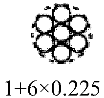


Second br aided layer *2 - - - - Twist direction of outermost layer steel filament First braided layer Z-wound steel cord S S S S S-wound steel cord S S S Z Second braided layer Z-wound steel cord - - - - S-wound steel cord - - - - Twist angle (°) of outermost layer steel filament First braided layer Z-wound steel cord 7 3.9 2.6 3.9 S-wound steel cord 7 3.9 2.6 3.9 Second braided layer Z-wound steel cord - - - - S-wound steel cord - - - - Crossing angle (°) of outermost layer steel filament First braided layer Z-wound inside, S-wound outside *3 84.6 78.4 75.8 70.6 S-wound inside, Z-wound outside *4 56.6 62.8 65.4 70.6 Second braided layer Z-wound inside, S-wound outside *3 - - - - S-wound inside, Z-wound outside *4 - - - - θo, θi(°) of first braided layer 120 60 60 60 Impact durability (10,000 times) 9 8 40 60 *1: First reinforcing layer having a braided structure counting from the hose radial inner side
*2: Second reinforcing layer having a braided structure counting from the hose radial inner side
*3: Portion where Z-wound steel cord is inside and S-wound steel cord is outside
*4: Portion where S-wound steel cord is inside and Z-wound steel cord is outside[Table 2] Example 3 Example 4 Example 5 Example 6 Cord structure First braided layer *1 


Second braided layer *2 
- 
- Twist direction of outermost layer steel filament First braided layer Z-wound steel cord S S S S S-wound steel cord Z Z Z Z Second braided layer Z-wound steel cord - - S - S-wound steel cord - - Z - Twist angle (°) of outermost layer steel filament First braided layer Z-wound steel cord 7 7 7 3.9 S-wound steel cord 7 7 7 3.9 Second braided layer Z-wound steel cord 0 - 7 - S-wound steel cord 0 - 7 - Crossing angle (°) of outermost layer steel filament First braided layer Z-wound inside, S-wound outside *3 70.6 70.6 70.6 70.6 S-wound inside, Z-wound outside *4 70.6 70.6 70.6 70.6 Second braided layer Z-wound inside, S-wound outside *3 70.6 - 70.6 - S-wound inside, Z-wound outside *4 70.6 - 70.6 - θo, θ1(°) of first braided layer 60 120 120 108 Impact durability (10,000 times) 70 80 80 70 
- Tables 1 to 3 show that the high pressure hose of the present invention has excellent impact durability.
-
- 10
- High pressure hose
- 11
- Reinforcing layer having a braided structure
- 12
- Inner rubber layer
- 13
- Outer rubber layer
- 20, 120
- Steel cord
Claims (4)
- A high pressure hose comprising at least one reinforcing layer having a braided structure in which a steel cord formed by twisting a plurality of steel filaments is braided, wherein
a crossing angle θ between an outermost layer steel filament of an S-wound steel cord and an outermost layer steel filament of a Z-wound steel cord of a reinforcing layer having a braided structure on an innermost in a hose radial direction of the reinforcing layers having a braided structure is 76° or less. - The high pressure hose according to claim 1, wherein a twist angle of a steel filament with respect to a cord axis in the S-wound steel cord and the Z-wound steel cord is from 2.8 to 10.5°.
- The high pressure hose according to claim 1 or 2, wherein the crossing angle θ is 76° or less in all the reinforcing layers of a braided structure.
- The high pressure hose according to any one of claims 1 to 3, wherein,
in a cross section perpendicular to the cord axis of each steel cord constituting the reinforcing layer having a braided structure,
when an angle formed by connecting a center point of a steel filament located at an outermost in the hose radial direction and center points of both adjacent steel filaments located in the same layer as the steel filament is θo, and
when an angle formed by connecting a center point of a steel filament located at an innermost in the hose radial direction and center points of both adjacent steel filaments located in the same layer as the steel filament is θi,
the θo and the θi are preferably 108° or more.
Applications Claiming Priority (2)
| Application Number | Priority Date | Filing Date | Title |
|---|---|---|---|
| JP2017156833A JP2019035461A (en) | 2017-08-15 | 2017-08-15 | High-pressure hose |
| PCT/JP2018/028319 WO2019035341A1 (en) | 2017-08-15 | 2018-07-27 | High pressure hose |
Publications (2)
| Publication Number | Publication Date |
|---|---|
| EP3670987A1 true EP3670987A1 (en) | 2020-06-24 |
| EP3670987A4 EP3670987A4 (en) | 2021-03-24 |
Family
ID=65362931
Family Applications (1)
| Application Number | Title | Priority Date | Filing Date |
|---|---|---|---|
| EP18846513.2A Withdrawn EP3670987A4 (en) | 2017-08-15 | 2018-07-27 | High pressure hose |
Country Status (5)
| Country | Link |
|---|---|
| US (1) | US20200182381A1 (en) |
| EP (1) | EP3670987A4 (en) |
| JP (1) | JP2019035461A (en) |
| CN (1) | CN110998158A (en) |
| WO (1) | WO2019035341A1 (en) |
Cited By (1)
| Publication number | Priority date | Publication date | Assignee | Title |
|---|---|---|---|---|
| EP4146970B1 (en) * | 2020-05-05 | 2024-04-17 | Neoperl GmbH | Hose, hose arrangement and corresponding process for manufacturing a hose arrangement |
Families Citing this family (3)
| Publication number | Priority date | Publication date | Assignee | Title |
|---|---|---|---|---|
| JP7542328B2 (en) | 2020-04-06 | 2024-08-30 | 株式会社ブリヂストン | hose |
| FR3129699B1 (en) * | 2021-12-01 | 2023-11-03 | Hutchinson | HOSE FOR TRANSPORTING A FLUID FOR A VEHICLE |
| WO2025187179A1 (en) * | 2024-03-08 | 2025-09-12 | 株式会社ブリヂストン | Hose |
Family Cites Families (11)
| Publication number | Priority date | Publication date | Assignee | Title |
|---|---|---|---|---|
| JPS4911450Y1 (en) * | 1968-10-01 | 1974-03-19 | ||
| JPH0612154B2 (en) * | 1985-02-28 | 1994-02-16 | 横浜ゴム株式会社 | Curved hose |
| JPH01104495U (en) * | 1987-12-30 | 1989-07-14 | ||
| DE69421090T2 (en) | 1993-12-15 | 2000-01-20 | N.V. Bekaert S.A., Zwevegem | OPEN STEEL CORD CONSTRUCTION |
| JP3714981B2 (en) * | 1994-12-07 | 2005-11-09 | 横浜ゴム株式会社 | Reinforced high pressure hose |
| JP4776455B2 (en) * | 2006-06-29 | 2011-09-21 | 株式会社ブリヂストン | Heavy duty pneumatic radial tire |
| DE102008055891A1 (en) * | 2008-11-05 | 2010-05-12 | Masterflex Ag | Flexible, electrically heated hose |
| JP4683150B2 (en) * | 2009-10-16 | 2011-05-11 | 横浜ゴム株式会社 | Pneumatic tire |
| DE112010004043B4 (en) * | 2009-10-16 | 2014-01-16 | The Yokohama Rubber Co., Ltd. | Steel cord for a pneumatic tire |
| JP5969163B2 (en) | 2010-08-04 | 2016-08-17 | 横浜ゴム株式会社 | Rubber hose |
| JP6152887B2 (en) * | 2015-12-10 | 2017-06-28 | 横浜ゴム株式会社 | High pressure hose |
-
2017
- 2017-08-15 JP JP2017156833A patent/JP2019035461A/en active Pending
-
2018
- 2018-07-27 EP EP18846513.2A patent/EP3670987A4/en not_active Withdrawn
- 2018-07-27 WO PCT/JP2018/028319 patent/WO2019035341A1/en not_active Ceased
- 2018-07-27 CN CN201880051044.3A patent/CN110998158A/en active Pending
-
2020
- 2020-02-14 US US16/791,397 patent/US20200182381A1/en not_active Abandoned
Cited By (1)
| Publication number | Priority date | Publication date | Assignee | Title |
|---|---|---|---|---|
| EP4146970B1 (en) * | 2020-05-05 | 2024-04-17 | Neoperl GmbH | Hose, hose arrangement and corresponding process for manufacturing a hose arrangement |
Also Published As
| Publication number | Publication date |
|---|---|
| JP2019035461A (en) | 2019-03-07 |
| WO2019035341A1 (en) | 2019-02-21 |
| CN110998158A (en) | 2020-04-10 |
| EP3670987A4 (en) | 2021-03-24 |
| US20200182381A1 (en) | 2020-06-11 |
Similar Documents
| Publication | Publication Date | Title |
|---|---|---|
| US20200182381A1 (en) | High pressure hose | |
| US20200003340A1 (en) | High pressure hose | |
| EP3027805B1 (en) | High elongation steel cord and pneumatic tire comprising said cord | |
| EP2423381B1 (en) | Rubber/steel cord composite and pneumatic radial tire | |
| EP1126073B1 (en) | Steel cord for reinforcing elastomeric articles | |
| EP3575631A1 (en) | Transmission v-belt and manufacturing method therefor | |
| JP2006507414A (en) | Flat helically wound tire cord | |
| JP2008285785A (en) | Cord for reinforcing rubber article, and tire | |
| JP5126979B2 (en) | Steel cords for reinforcing rubber articles and pneumatic tires | |
| JP7323551B2 (en) | actuator | |
| JP7278744B2 (en) | Cord for elastomer reinforcement | |
| JP2009024268A (en) | Cord for reinforcing rubber article and pneumatic tire | |
| US11118708B2 (en) | High pressure hose | |
| JP7278745B2 (en) | Cord for elastomer reinforcement | |
| JP6892292B2 (en) | High pressure hose | |
| JP6258760B2 (en) | High pressure hose | |
| JP7128834B2 (en) | tire | |
| JP2006307987A (en) | hose | |
| JP2022113350A (en) | Hose and use method for hose | |
| CN106232378A (en) | Including the rubber composition thickness reduced and the tire of covering carcass framework reinforcement element | |
| JP2009274798A (en) | Conveyor belt | |
| JP2006249636A (en) | Steel cord |
Legal Events
| Date | Code | Title | Description |
|---|---|---|---|
| STAA | Information on the status of an ep patent application or granted ep patent |
Free format text: STATUS: THE INTERNATIONAL PUBLICATION HAS BEEN MADE |
|
| PUAI | Public reference made under article 153(3) epc to a published international application that has entered the european phase |
Free format text: ORIGINAL CODE: 0009012 |
|
| STAA | Information on the status of an ep patent application or granted ep patent |
Free format text: STATUS: REQUEST FOR EXAMINATION WAS MADE |
|
| 17P | Request for examination filed |
Effective date: 20200310 |
|
| AK | Designated contracting states |
Kind code of ref document: A1 Designated state(s): AL AT BE BG CH CY CZ DE DK EE ES FI FR GB GR HR HU IE IS IT LI LT LU LV MC MK MT NL NO PL PT RO RS SE SI SK SM TR |
|
| AX | Request for extension of the european patent |
Extension state: BA ME |
|
| DAV | Request for validation of the european patent (deleted) | ||
| DAX | Request for extension of the european patent (deleted) | ||
| A4 | Supplementary search report drawn up and despatched |
Effective date: 20210219 |
|
| RIC1 | Information provided on ipc code assigned before grant |
Ipc: F16L 11/08 20060101AFI20210215BHEP |
|
| STAA | Information on the status of an ep patent application or granted ep patent |
Free format text: STATUS: THE APPLICATION IS DEEMED TO BE WITHDRAWN |
|
| 18D | Application deemed to be withdrawn |
Effective date: 20210921 |