EP3670932B1 - Dispositif d'assemblage de type verrou par mecanisme de coins bidirectionnel - Google Patents
Dispositif d'assemblage de type verrou par mecanisme de coins bidirectionnel Download PDFInfo
- Publication number
- EP3670932B1 EP3670932B1 EP19213238.9A EP19213238A EP3670932B1 EP 3670932 B1 EP3670932 B1 EP 3670932B1 EP 19213238 A EP19213238 A EP 19213238A EP 3670932 B1 EP3670932 B1 EP 3670932B1
- Authority
- EP
- European Patent Office
- Prior art keywords
- bolt
- cam
- axis
- interaction
- interaction surface
- Prior art date
- Legal status (The legal status is an assumption and is not a legal conclusion. Google has not performed a legal analysis and makes no representation as to the accuracy of the status listed.)
- Active
Links
- 230000007246 mechanism Effects 0.000 title description 8
- 230000002457 bidirectional effect Effects 0.000 title description 3
- 230000003993 interaction Effects 0.000 claims description 137
- 238000006073 displacement reaction Methods 0.000 description 9
- 230000000295 complement effect Effects 0.000 description 8
- 230000005540 biological transmission Effects 0.000 description 4
- 230000005855 radiation Effects 0.000 description 4
- 230000000712 assembly Effects 0.000 description 2
- 238000000429 assembly Methods 0.000 description 2
- 230000008901 benefit Effects 0.000 description 2
- 230000001627 detrimental effect Effects 0.000 description 2
- 230000002427 irreversible effect Effects 0.000 description 2
- 230000002441 reversible effect Effects 0.000 description 2
- 230000001131 transforming effect Effects 0.000 description 2
- 230000001133 acceleration Effects 0.000 description 1
- 230000009471 action Effects 0.000 description 1
- 230000000694 effects Effects 0.000 description 1
- 238000003754 machining Methods 0.000 description 1
- 238000004519 manufacturing process Methods 0.000 description 1
- 231100000331 toxic Toxicity 0.000 description 1
- 230000002588 toxic effect Effects 0.000 description 1
- 230000009466 transformation Effects 0.000 description 1
- 238000003466 welding Methods 0.000 description 1
Images


Classifications
-
- F—MECHANICAL ENGINEERING; LIGHTING; HEATING; WEAPONS; BLASTING
- F16—ENGINEERING ELEMENTS AND UNITS; GENERAL MEASURES FOR PRODUCING AND MAINTAINING EFFECTIVE FUNCTIONING OF MACHINES OR INSTALLATIONS; THERMAL INSULATION IN GENERAL
- F16B—DEVICES FOR FASTENING OR SECURING CONSTRUCTIONAL ELEMENTS OR MACHINE PARTS TOGETHER, e.g. NAILS, BOLTS, CIRCLIPS, CLAMPS, CLIPS OR WEDGES; JOINTS OR JOINTING
- F16B5/00—Joining sheets or plates, e.g. panels, to one another or to strips or bars parallel to them
- F16B5/06—Joining sheets or plates, e.g. panels, to one another or to strips or bars parallel to them by means of clamps or clips
- F16B5/0607—Joining sheets or plates, e.g. panels, to one another or to strips or bars parallel to them by means of clamps or clips joining sheets or plates to each other
- F16B5/0621—Joining sheets or plates, e.g. panels, to one another or to strips or bars parallel to them by means of clamps or clips joining sheets or plates to each other in parallel relationship
- F16B5/0635—Joining sheets or plates, e.g. panels, to one another or to strips or bars parallel to them by means of clamps or clips joining sheets or plates to each other in parallel relationship fastened over the edges of the sheets or plates
-
- F—MECHANICAL ENGINEERING; LIGHTING; HEATING; WEAPONS; BLASTING
- F16—ENGINEERING ELEMENTS AND UNITS; GENERAL MEASURES FOR PRODUCING AND MAINTAINING EFFECTIVE FUNCTIONING OF MACHINES OR INSTALLATIONS; THERMAL INSULATION IN GENERAL
- F16B—DEVICES FOR FASTENING OR SECURING CONSTRUCTIONAL ELEMENTS OR MACHINE PARTS TOGETHER, e.g. NAILS, BOLTS, CIRCLIPS, CLAMPS, CLIPS OR WEDGES; JOINTS OR JOINTING
- F16B5/00—Joining sheets or plates, e.g. panels, to one another or to strips or bars parallel to them
- F16B5/0004—Joining sheets, plates or panels in abutting relationship
- F16B5/0008—Joining sheets, plates or panels in abutting relationship by moving the sheets, plates or panels substantially in their own plane, perpendicular to the abutting edge
- F16B5/0024—Joining sheets, plates or panels in abutting relationship by moving the sheets, plates or panels substantially in their own plane, perpendicular to the abutting edge the sheets, plates or panels having holes, e.g. for dowel- type connections
-
- F—MECHANICAL ENGINEERING; LIGHTING; HEATING; WEAPONS; BLASTING
- F16—ENGINEERING ELEMENTS AND UNITS; GENERAL MEASURES FOR PRODUCING AND MAINTAINING EFFECTIVE FUNCTIONING OF MACHINES OR INSTALLATIONS; THERMAL INSULATION IN GENERAL
- F16B—DEVICES FOR FASTENING OR SECURING CONSTRUCTIONAL ELEMENTS OR MACHINE PARTS TOGETHER, e.g. NAILS, BOLTS, CIRCLIPS, CLAMPS, CLIPS OR WEDGES; JOINTS OR JOINTING
- F16B7/00—Connections of rods or tubes, e.g. of non-circular section, mutually, including resilient connections
- F16B7/02—Connections of rods or tubes, e.g. of non-circular section, mutually, including resilient connections with conical parts
- F16B7/025—Connections of rods or tubes, e.g. of non-circular section, mutually, including resilient connections with conical parts with the expansion of an element inside the tubes due to axial movement towards a wedge or conical element
Definitions
- the invention lies in the field of reversible mechanical assemblies. It relates to an assembly device between two mechanical parts capable of comprising bores for receiving the elements of the assembly device.
- the invention applies in particular to the assembly of mechanical parts subjected to severe environments and / or whose reliability is critical for safety.
- a harsh environment is for example characterized by a toxic and / or corrosive environment, and / or by the presence of strong mechanical stresses, vibrations, significant accelerations and / or harmful radiation such as ionizing, neutron, X and X radiation. gamma.
- the invention applies more generally to any assembly between two mechanical parts.
- assemblies subjected to neutron radiation are generally produced by welding or by screwing, depending on the need for reversibility of the assembly.
- Screw connections can prove to be complicated to implement in a nuclear environment. Indeed, the screws are assembly members of relatively small dimensions and involve, for their screwing and unscrewing, a combined action of rotation and translation. However, the screws are not directly accessible to operators but must be handled by means of robots, possibly in confined spaces. The use of relatively sophisticated robots, able to perform precise movements of low amplitude, is therefore necessary for handling screws and assembling the parts.
- the Applicant has sought to use various assembly mechanisms avoiding the use of screws. Nevertheless, the assembly mechanisms of the state of the art often include numerous parts interacting with one another. This results in a lack of reliability of the mechanisms. In addition, some assembly mechanisms require the presence of a spring used for the return of one or more parts. However, in the presence of neutron radiation, the elastic properties of a spring are modified. The spring can lose its elastic properties in just a few months and make the mechanism inoperative.
- the document EP 0 398 239 A shows a locking device according to the prior art.
- An aim of the invention is therefore to provide an assembly device of simple design which remains reliable even in a harsh environment.
- the invention is based on a combination of two one-piece parts arranged to form a lock incorporating a bidirectional wedge mechanism.
- a first part called a “cam”
- a second part called a “bolt”
- the cam is arranged to be housed in a first bore formed in one of the mechanical parts to be assembled and to be guided therein in translation.
- the bolt is designed to be housed in a second bore formed in the same part and to be guided therein in translation. The second bore opens into the first bore to allow interaction between the cam and the bolt.
- the bolt is also designed to be able to be received by a translational movement in a third bore formed in the other part, this third bore extending the second bore in an assembly position between the two parts.
- the cam and the bolt each comprise two interaction surfaces forming a wedge system which can be qualified as "bidirectional" or "double".
- the interaction surfaces are arranged so that a translational movement of the cam in the first bore, in each direction, causes a translational movement of the bolt in the second and third bores, in a corresponding direction.
- the bolt is moved between an unlocked position, in which it is only housed in the second bore, and a locked position, in which it is housed in both the second and the third bore.
- the assembly device comprises, in addition to the two parts to be assembled, only two single-piece parts, the shapes of which can be relatively simple.
- the cam and the bolt can generally have a cylindrical shape capable of allowing them to be guided in translation. They can in particular have a cylindrical shape of revolution.
- the translational guidance of the cam in the cam guide bore and the translational guidance of the bolt in the bolt guide bore may correspond to a sliding connection or to a sliding pivot connection.
- the interaction between the cam and the bolt towards the locked position is, in practice, carried out by providing that at least one of the first and third interaction surfaces extends concomitantly along the first axis and along the second axis.
- the interaction between the cam and the bolt towards the unlocked position is achieved by providing for at least one of the second and fourth interaction surfaces to extend concomitantly along the first axis and along the second axis.
- the cam and the bolt, and in particular their interaction surfaces thus form a mechanism for transforming a translational movement along a first axis into a translational movement along a second axis, not parallel to the first.
- At least one of the first interaction surface, the second interaction surface, the third interaction surface and the fourth interaction surface is curved.
- Such a domed shape makes it possible to generate a kinematic transmission ratio of movement and of variable force along the travel path of the cam and the bolt.
- At least one of the first interaction surface, the second interaction surface, the third interaction surface and the fourth interaction surface is planar.
- a flat surface makes it possible to generate a kinematic transmission ratio of movement and constant force over the entire travel path of the cam and the bolt.
- flat surfaces have the advantage of being easy to produce by machining.
- each of the interaction surfaces of the cam and the bolt is planar.
- the first interaction surface of the cam and the third interaction surface of the bolt are plane and parallel to each other.
- the second interaction surface of the cam and the fourth interaction surface of the bolt are plane and parallel to each other. Planar and parallel interaction surfaces make it possible to maximize the contact surface and therefore limit their wear.
- the second axis that is to say the axis along which the bolt guide bore extends, may be perpendicular to the first axis, that is to say the axis along which the bolt extends. cam guide bore.
- the first interaction surface of the cam and the third interaction surface of the bolt are arranged so as to prevent a movement of the bolt towards the locked position causing a translational movement of the cam according to the first axis in the first direction.
- the second interaction surface of the cam and the fourth interaction surface of the bolt are arranged so as to prevent a movement of the bolt towards the unlocked position causing a displacement in translation of the cam along the first axis in the second direction.
- the movement of the bolt can be controlled by the movement of the cam, but not vice versa.
- the assembly device is irreversible in the movement of the bolt.
- the first and second variant embodiments can be obtained by limiting the angle formed between these surfaces and a plane perpendicular to the second axis.
- the value of the limiting angle shall be determined as a function of the coefficient of adhesion friction or the coefficient of sliding friction.
- the coefficients of friction of adhesion and of sliding are less than 0.25.
- the limiting angle is approximately equal to 25 °.
- the first interaction surface of the cam and the third interaction surface of the bolt can each extend in an interaction plane forming an angle less than or equal to 25 ° with respect to a plane perpendicular to the second axis.
- the second interaction surface of the cam and the fourth interaction surface of the bolt can each extend in an interaction plane forming an angle less than or equal to 25 ° with respect to the perpendicular plane. to the second axis.
- lower limit angle values can be used, for example 10 °, 15 ° or 20 °.
- the first interaction surface of the cam and the third interaction surface of the bolt are arranged so as to allow movement of the bolt towards the locked position. a translational movement of the cam along the first axis in the first direction.
- the second interaction surface of the cam and the fourth interaction surface of the bolt are arranged so as to allow a movement of the bolt to the unlocked position causes a displacement in translation of the cam along the first axis in the second direction.
- the movement of the cam can be controlled by the bolt.
- the assembly device is reversible in the movement of the bolt.
- the third and fourth variant embodiments can be obtained by placing the angle formed between these surfaces and a plane perpendicular to the second axis within a range of values determined in function of the coefficient of friction of adhesion or of the coefficient of sliding friction.
- the coefficients of friction of adhesion and of sliding are less than 0.25.
- a range of values between 25 ° and 65 ° must allow reversibility of the assembly device.
- the first interaction surface of the cam and the third interaction surface of the bolt can each extend in an interaction plane forming an angle of between 25 ° and 65 ° with respect to to the plane perpendicular to the second axis.
- the second interaction surface of the cam and the fourth interaction surface of the bolt can each extend in an interaction plane forming an angle of between 25 ° and 65 ° with respect to the plane. perpendicular to the second axis.
- the cam comprises a first and a second guide leg extending parallel to the first axis and being arranged on either side of the first and second interaction surface, the first guide leg comprising a first lateral bearing surface extending in a first plane parallel to the first and second axes, the second guide leg comprising a second lateral bearing surface extending in a second plane parallel to the first and second axes, the bolt comprising a first and a second through openings extending parallel to the first axis and being arranged on either side of the third and fourth interaction surfaces, the first through opening defining a third lateral bearing surface and the second through opening defining a fourth lateral bearing surface, the first and third lateral bearing surfaces being arranged to be able to interact so as to guide in translation according to the first and second axes the movement of the bolt relative to the cam, and the second and fourth lateral bearing surfaces being arranged to be able to interact so as to guide in translation along the first and second axes the movement of the bolt relative to the cam.
- each guide leg may include an outer guide surface the shape of which is complementary to that of the cam guide bore.
- the guide legs participate in guiding in translation along the first axis of the cam in said cam guide bore.
- the outer guide surfaces are advantageously arranged to have a playful fit in the cam guide bore.
- the cam comprises a guide section and an interaction section.
- the guide section has a surface complementary to the cam guide bore, so as to guide the cam in translation along the first axis in said cam guide bore.
- the guide section and the cam guide bore for example have a cylindrical surface along the first axis.
- the cylindrical surface may have a circular section.
- the guide section and the cam guide bore are arranged to have a clearance between them.
- the interaction section comprises the first and second interaction surfaces. When the cam comprises guide legs extending on either side of the first and second interaction surfaces, the interaction section provides both a function of transforming the movement and a function of guiding in translation according to the first axis.
- the subject of the invention is also an assembly comprising a first part, a second part, and an assembly device as described above.
- the first part comprises a cam guide bore extending along a first axis and a bolt guide bore extending along a second axis, not parallel to the first axis, the bolt guide bore opening into the bore. cam guide.
- the second part comprises an assembly bore extending along a third axis. The first and second parts are arranged so that, in an assembly position, the bolt guide bore and the assembly bore open into one another, the second and third axes preferably being the same.
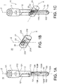
- the figures 1A, 1B and 1C represent, in a perspective view, an example of an assembly device according to the invention.
- the assembly device 1 comprises a cam 10 and a bolt 20 able to cooperate with each other to effect a transformation of movement and to obtain an assembly between two mechanical parts, not shown in these figures.
- the figure 1A represents only cam 10
- the figure 1B represents only the bolt 20
- the figure 1C shows cam 10 and bolt 20 in an assembled configuration.
- the cam 10 successively comprises, following an axis Z, a head 11, a guide section 12 and an interaction section 13.
- the head 11, the guide section 12 and the interaction section 13 each have an overall shape. circular cylindrical along the Z axis.
- the head 11 comprises a housing 111 extending along the Z axis and opening onto a first longitudinal end of the cam 10.
- the housing 111 may include an internal thread, not shown, allowing attachment to a robotic arm.
- the guide section 12 has a cylindrical shape of revolution along the Z axis, with the exception of two flats 121 extending in planes parallel to an XZ plane passing the Z axis and an X axis, perpendicular to the Z axis.
- the flats 121 are able to balance a torsional moment which would be exerted on the cam along the Z axis and to limit a displacement travel in translation along the Z axis of the cam 10.
- the flats 121 are not essential for the operation of the assembly device 1, in particular in the absence of application of a possibly detrimental torque to the cam and the bolt and in the event of controlled cam travel.
- the diameter of the guide section 12 is smaller than the diameter of the head 11, so that a first shoulder 112 is formed. This shoulder makes it possible to constitute a particularly resistant support but is not essential for operation.
- the interaction section 13 comprises an interaction member 131 having a first interaction surface 13A and a second interaction surface 13B.
- the interaction surfaces 13A, 13B are plane and parallel to each other.
- each interaction surface 13A, 13B is inscribed in a plane inclined with respect to the X and Z axes.
- each interaction surface 13A, 13B extends in a plane forming an angle ⁇ , shown in figure 3A , equal to 30 °.
- the interaction section 13 further comprises a first guide leg 132 and a second guide leg 133.
- the guide legs 132, 133 extend parallel to the Z axis, on either side of the member. interaction 131.
- the guide leg 132 has a first lateral bearing surface 132A and a first external guide surface 132B.
- the guide leg 133 has a second lateral bearing surface 133A and a second external guide surface 133B.
- Each lateral bearing surface 132A, 133A is flat and extends in a plane parallel to the XZ plane.
- Each outer guide surface 132B, 133B is cylindrical of revolution about the Z axis.
- the diameter of the guide legs 132, 133, at the level of the outer guide surfaces 132B, 133B, is less than the diameter of the guide section 12, so that a second shoulder 113 is formed between the guide section 12 and the interaction section 13.
- the cam 10 shown in figures 1A, 1B and 1C corresponds to a particular formatting of the invention.
- the shoulder 113 is not essential for the operation of the assembly device 1.
- the cam could have a simpler shape, namely a generally cylindrical shape of revolution with an interaction section. integrated in the same diameter, the cam stroke can then be limited elsewhere and the transmission of a torque likely to be detrimental to the section interaction that can also be prevented elsewhere, for example by means of flats, as in the example of figures 1A, 1B and 1C .
- the bolt 20 generally has a cylindrical shape of revolution along the X axis. It comprises a through hole 21 forming a third interaction surface 21A and a fourth interaction surface 21B.
- the interaction surfaces 21A, 21B are plane and parallel to each other. They are also parallel to the interaction surfaces 13A, 13B of the cam 10.
- the cam 10 and the bolt 20 are arranged so that the interaction surfaces 13A and 21A can come into contact with each other to interact.
- a displacement in translation, in a first direction along the Z axis (downward on the figure 1C ) causes a translational movement, in a first direction along the X axis (to the right on the figure 1C ), the bolt 20.
- the cam 10 and the bolt 20 are further arranged so that the interaction surfaces 13B and 21B can come into contact with each other to interact.
- a displacement in translation, in a second direction along the Z axis (upwards on the figure 1C ), of the cam 10 causes a translational movement, in a second direction along the X axis (to the left on the figure 1C ), the bolt 20.
- the bolt 20 further comprises a first through opening 22 and a second through opening 23.
- the through openings 22 and 23 extend parallel to the Z axis, on either side of the through hole 21 They are arranged so that they can each receive a guide leg 132, 133 and allow their displacement in translation with respect to the bolt 20 both along the Z axis and along the X axis.
- through opening 22 defines a third lateral bearing surface 22A, parallel to the first lateral bearing surface 132A of the first guide leg 132, and able to come into contact with it to guide the first guide leg 132 in translation.
- L 'through opening 23 defines a fourth lateral support surface 23A, parallel to the second lateral support surface 133A of the second guide leg 133, and able to come into contact with it to guide the second guide leg 133 in translation.
- the figures 2A and 2B respectively show, in a perspective view, an example of a first part 30 configured to accommodate the assembly device 1 of the figures 1A, 1B and 1C , and said assembly device 1 mounted in the part 30.
- the part 30 comprises an outer surface 30A of cylindrical shape of revolution along the Z axis, a bearing surface 30B, a first cam guide bore 31 and a second cam guide bore 32 each extending along the Z axis.
- the bearing surface 30B extends in a plane parallel to an XY plane, passing the X axis and a Y axis, the X, Y axes and Z defining an orthogonal coordinate system.
- the bearing surface 30B forms a surface on which the shoulder 112 of the cam 10 can come to rest.
- the cam guide bore 31 has a cylindrical shape of revolution along the Z axis, complementary to the shape of the guide section 12 of the cam 10.
- the cam guide bore 32 has a cylindrical shape of revolution along l 'Z axis, complementary to the shape of the interaction section 13, and more particularly of the outer guide surfaces 132B, 133B.
- the cam 10 can then be mounted in a sliding pivot connection along the Z axis in the part 30.
- the cam guide bore 32 opens into the cam guide bore 31 and has a diameter smaller than that of the bore. guide 31, so as to form a shoulder 33.
- the part 30 further comprises a bolt guide bore 34 extending along the X axis through the cam guide bore 32.
- the bore of bolt guide 34 has a cylindrical shape of revolution along the X axis, complementary to the shape of the bolt 20.
- the bolt 20 can then be mounted in a sliding pivot connection along the X axis in the part 30.
- the part 30 comprises of plus through openings 35, 36 extending parallel to the X axis and making it possible to accommodate screws, not shown, capable of preventing rotation along the Z axis of the cam 10 in the part 30.
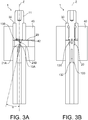
- the figures 3A and 3B show the assembly device 1 and the first part 30 mounted in a second part 40, in a locked configuration. They respectively represent these elements in a section view along the XZ plane and along a YZ plane.
- the second part 40 comprises a through opening 41 extending along the Z axis and having a cylindrical shape of revolution according to this same Z axis, the shape being complementary to that of the outer surface 30A of the first part 30, so as to accommodate it.
- the second part 40 further comprises an assembly bore 42 extending along the X axis and having a cylindrical shape of revolution along the X axis, complementary to that of the bolt 20.
- the cam 10 is inserted as far as possible into the first part 30, the shoulder 112 being supported on the bearing surface 30B.
- the bolt 20 is inserted both into the bolt guide bore 34 of the first part 30 and into the assembly bore 42 of the second part 40.
- the figures 4A and 4B show the assembly device 1 and the first part 30 mounted in the second part 40, in an unlocked configuration. They represent these elements in the respective views of the figures 3A and 3B .
- the cam 10 is raised relative to the locked configuration, the shoulder 112 not being supported on the bearing surface 30B.
- the bolt 20 is inserted into the bolt guide bore 34 of the first part 30 but not into the assembly bore 42 of the second part 40.
- the passage from the unlocked configuration to the locked configuration is effected by downward displacement of the cam 10.
- the interaction surface 13A of the cam 10 exerts a force on the interaction surface 21A of the bolt 20, causing its displacement. to the right on the figures 3A and 4A .
- the passage from the locked configuration to the unlocked configuration is effected by upward movement of the cam 10.
- the interaction surface 13B of the cam 10 exerts a force on the interaction surface 21B of the bolt 20, causing it to move. to the left on the figures 3A and 4A .
- the figure 5 shows, in a view in longitudinal section, an example of an assembly comprising two ferrules and two examples of assembly devices according to the invention.
- the ferrules 50, 60 are in the form of hollow tubes and are positioned in an assembly configuration by means of forms complementary formed in their walls 51, 61.
- the ferrule 50 comprises a first cam guide bore 52 and a second cam guide bore 53 extending concentrically along a first axis Z1, and a first bolt guide bore 54 extending along an axis X.
- the ferrule 50 further comprises a third cam guide bore 55 and a fourth cam guide bore 56 extending concentrically along a second axis Z2, and a second guide bore bolt 57 extending along the X axis.
- the cam guide bores 52, 53 and the bolt guide bore 54 receive a first assembly device 101 and the cam guide bores 55, 56 and the bolt guide bore 57 receive a second device assembly 102.
- the assembly devices 101, 102 are identical to the assembly device 1 described with reference to figures 1A to 1C , except that they also each have a rod 1011, 1021 connecting the guide section 12 to the interaction section 13.
- the presence of rods 1011, 1021 allows the heads 11 of the cams 10 to be moved away from the interaction sections 13.
- the ferrule 60 has two assembly bores 62, 63 each extending along the X axis and each arranged to receive a bolt 20 in the locked configuration.
- the assembly device is reduced to two single-piece parts of relatively simple shapes. This results in simplicity of manufacture and robustness of operation. Furthermore, the cam and the bolt are largely guided in their respective bores, thus providing excellent mechanical strength, including in the event of transmission of forces between the two parts to be assembled.
- the assembly device is compact and can be integrated into any type of part to be assembled.
Landscapes
- Engineering & Computer Science (AREA)
- General Engineering & Computer Science (AREA)
- Mechanical Engineering (AREA)
- Steering Controls (AREA)
- Connection Of Plates (AREA)
- Clamps And Clips (AREA)
- Automatic Assembly (AREA)
Applications Claiming Priority (1)
| Application Number | Priority Date | Filing Date | Title |
|---|---|---|---|
| FR1873204A FR3090051B1 (fr) | 2018-12-18 | 2018-12-18 | dispositif d’assemblage de type verrou par mécanisme de coins bidirectionnel |
Publications (2)
| Publication Number | Publication Date |
|---|---|
| EP3670932A1 EP3670932A1 (fr) | 2020-06-24 |
| EP3670932B1 true EP3670932B1 (fr) | 2021-09-29 |
Family
ID=66690521
Family Applications (1)
| Application Number | Title | Priority Date | Filing Date |
|---|---|---|---|
| EP19213238.9A Active EP3670932B1 (fr) | 2018-12-18 | 2019-12-03 | Dispositif d'assemblage de type verrou par mecanisme de coins bidirectionnel |
Country Status (3)
| Country | Link |
|---|---|
| EP (1) | EP3670932B1 (es) |
| ES (1) | ES2901325T3 (es) |
| FR (1) | FR3090051B1 (es) |
Family Cites Families (5)
| Publication number | Priority date | Publication date | Assignee | Title |
|---|---|---|---|---|
| FR2638210B1 (fr) * | 1988-10-20 | 1990-12-21 | Sarel Sa | Piece de liaison destinee a l'assemblage de profiles |
| JPH0295897U (es) * | 1988-11-16 | 1990-07-31 | ||
| US5018772A (en) * | 1989-05-16 | 1991-05-28 | Westinghouse Electric Corp. | Latching device for securing a closure to a cask for transporting radioactive waste |
| US7891904B2 (en) * | 2006-06-12 | 2011-02-22 | David Stadler | Manhole cover stop mechanism |
| US9068634B2 (en) * | 2013-11-06 | 2015-06-30 | Kan Cui | Radially engaging system |
-
2018
- 2018-12-18 FR FR1873204A patent/FR3090051B1/fr active Active
-
2019
- 2019-12-03 ES ES19213238T patent/ES2901325T3/es active Active
- 2019-12-03 EP EP19213238.9A patent/EP3670932B1/fr active Active
Also Published As
| Publication number | Publication date |
|---|---|
| FR3090051A1 (fr) | 2020-06-19 |
| FR3090051B1 (fr) | 2021-01-08 |
| EP3670932A1 (fr) | 2020-06-24 |
| ES2901325T3 (es) | 2022-03-22 |
Similar Documents
| Publication | Publication Date | Title |
|---|---|---|
| EP1738229B1 (fr) | Couronne pour pièce d'horlogerie avec dispositif de débrayage | |
| EP0080416B1 (fr) | Dispositif d'actionnement et son application à un asservissement de position pour un télémanipulateur maître-esclave | |
| EP0551045B1 (fr) | Dispositif de contrÔle de dimensions d'un objet, en particulier de diamètres extérieurs ou intérieurs de pièces mécaniques | |
| EP2205890A2 (fr) | Dispositif de controle d'un dispositif amortisseur hydraulique de suspension | |
| EP2164685A1 (fr) | Pince pour robot manipulateur a precision de serrage amelioree et robot manipulateur comportant au moins une telle pince | |
| EP3208666A1 (fr) | Roue d'horlogerie a rattrapage de jeu | |
| EP2990882B1 (fr) | Balancier à réglage d'inertie | |
| EP2261521B1 (fr) | Ensemble d'articulation mécanique et procédé pour assembler un tel ensemble | |
| EP0547970B1 (fr) | Elément de connecteur électrique fixable de façon flottante sur un organe de support | |
| EP3670932B1 (fr) | Dispositif d'assemblage de type verrou par mecanisme de coins bidirectionnel | |
| FR3043801A3 (fr) | Balancier a reglage d'inertie | |
| CH691276A5 (fr) | Charnière élastique. | |
| CH711766A2 (fr) | Balancier à réglage d'inertie. | |
| EP4127858B1 (fr) | Interface homme-machine | |
| FR3026767A1 (es) | ||
| FR3011304A1 (fr) | Dispositif de transmission de mouvement sans jeu a un capteur de position et dispositif de detection de position correspondant | |
| CH712143A2 (fr) | Roue d'horlogerie à rattrapage de jeu. | |
| FR3048927A1 (fr) | Dispositif de generation d'effort | |
| FR2850935A1 (fr) | Dispositif de blocage vertical d'une colonne de direction de vehicule automobile | |
| WO2022238657A1 (fr) | Dispositif de commande | |
| EP3356892A1 (fr) | Composant mécanique à guidage flexible, notamment pour mouvement horloger | |
| FR3081836A1 (fr) | Ensemble propulsif d'aeronef et procede de verification de l'integrite d'une attache moteur de l'ensemble propulsif | |
| EP3844405B1 (fr) | Dispositif de connexion d'elements tubulaires | |
| EP3775578B1 (fr) | Servovalve de régulation de débit ou de pression d'un fluide | |
| EP0184889B1 (fr) | Dispositif égalisateur pour des correcteurs multiples de freinage asservis à la charge du véhicule |
Legal Events
| Date | Code | Title | Description |
|---|---|---|---|
| PUAI | Public reference made under article 153(3) epc to a published international application that has entered the european phase |
Free format text: ORIGINAL CODE: 0009012 |
|
| STAA | Information on the status of an ep patent application or granted ep patent |
Free format text: STATUS: REQUEST FOR EXAMINATION WAS MADE |
|
| 17P | Request for examination filed |
Effective date: 20191203 |
|
| AK | Designated contracting states |
Kind code of ref document: A1 Designated state(s): AL AT BE BG CH CY CZ DE DK EE ES FI FR GB GR HR HU IE IS IT LI LT LU LV MC MK MT NL NO PL PT RO RS SE SI SK SM TR |
|
| AX | Request for extension of the european patent |
Extension state: BA ME |
|
| RIC1 | Information provided on ipc code assigned before grant |
Ipc: F16B 5/00 20060101AFI20210326BHEP Ipc: F16B 5/06 20060101ALI20210326BHEP Ipc: F16B 7/02 20060101ALI20210326BHEP |
|
| GRAP | Despatch of communication of intention to grant a patent |
Free format text: ORIGINAL CODE: EPIDOSNIGR1 |
|
| STAA | Information on the status of an ep patent application or granted ep patent |
Free format text: STATUS: GRANT OF PATENT IS INTENDED |
|
| INTG | Intention to grant announced |
Effective date: 20210514 |
|
| GRAS | Grant fee paid |
Free format text: ORIGINAL CODE: EPIDOSNIGR3 |
|
| GRAA | (expected) grant |
Free format text: ORIGINAL CODE: 0009210 |
|
| STAA | Information on the status of an ep patent application or granted ep patent |
Free format text: STATUS: THE PATENT HAS BEEN GRANTED |
|
| AK | Designated contracting states |
Kind code of ref document: B1 Designated state(s): AL AT BE BG CH CY CZ DE DK EE ES FI FR GB GR HR HU IE IS IT LI LT LU LV MC MK MT NL NO PL PT RO RS SE SI SK SM TR |
|
| REG | Reference to a national code |
Ref country code: GB Ref legal event code: FG4D Free format text: NOT ENGLISH |
|
| REG | Reference to a national code |
Ref country code: CH Ref legal event code: EP Ref country code: AT Ref legal event code: REF Ref document number: 1434441 Country of ref document: AT Kind code of ref document: T Effective date: 20211015 |
|
| REG | Reference to a national code |
Ref country code: DE Ref legal event code: R096 Ref document number: 602019008011 Country of ref document: DE |
|
| REG | Reference to a national code |
Ref country code: IE Ref legal event code: FG4D Free format text: LANGUAGE OF EP DOCUMENT: FRENCH |
|
| REG | Reference to a national code |
Ref country code: LT Ref legal event code: MG9D |
|
| PG25 | Lapsed in a contracting state [announced via postgrant information from national office to epo] |
Ref country code: RS Free format text: LAPSE BECAUSE OF FAILURE TO SUBMIT A TRANSLATION OF THE DESCRIPTION OR TO PAY THE FEE WITHIN THE PRESCRIBED TIME-LIMIT Effective date: 20210929 Ref country code: SE Free format text: LAPSE BECAUSE OF FAILURE TO SUBMIT A TRANSLATION OF THE DESCRIPTION OR TO PAY THE FEE WITHIN THE PRESCRIBED TIME-LIMIT Effective date: 20210929 Ref country code: LT Free format text: LAPSE BECAUSE OF FAILURE TO SUBMIT A TRANSLATION OF THE DESCRIPTION OR TO PAY THE FEE WITHIN THE PRESCRIBED TIME-LIMIT Effective date: 20210929 Ref country code: BG Free format text: LAPSE BECAUSE OF FAILURE TO SUBMIT A TRANSLATION OF THE DESCRIPTION OR TO PAY THE FEE WITHIN THE PRESCRIBED TIME-LIMIT Effective date: 20211229 Ref country code: HR Free format text: LAPSE BECAUSE OF FAILURE TO SUBMIT A TRANSLATION OF THE DESCRIPTION OR TO PAY THE FEE WITHIN THE PRESCRIBED TIME-LIMIT Effective date: 20210929 Ref country code: FI Free format text: LAPSE BECAUSE OF FAILURE TO SUBMIT A TRANSLATION OF THE DESCRIPTION OR TO PAY THE FEE WITHIN THE PRESCRIBED TIME-LIMIT Effective date: 20210929 Ref country code: NO Free format text: LAPSE BECAUSE OF FAILURE TO SUBMIT A TRANSLATION OF THE DESCRIPTION OR TO PAY THE FEE WITHIN THE PRESCRIBED TIME-LIMIT Effective date: 20211229 |
|
| REG | Reference to a national code |
Ref country code: NL Ref legal event code: MP Effective date: 20210929 |
|
| REG | Reference to a national code |
Ref country code: AT Ref legal event code: MK05 Ref document number: 1434441 Country of ref document: AT Kind code of ref document: T Effective date: 20210929 |
|
| PG25 | Lapsed in a contracting state [announced via postgrant information from national office to epo] |
Ref country code: LV Free format text: LAPSE BECAUSE OF FAILURE TO SUBMIT A TRANSLATION OF THE DESCRIPTION OR TO PAY THE FEE WITHIN THE PRESCRIBED TIME-LIMIT Effective date: 20210929 Ref country code: GR Free format text: LAPSE BECAUSE OF FAILURE TO SUBMIT A TRANSLATION OF THE DESCRIPTION OR TO PAY THE FEE WITHIN THE PRESCRIBED TIME-LIMIT Effective date: 20211230 |
|
| REG | Reference to a national code |
Ref country code: ES Ref legal event code: FG2A Ref document number: 2901325 Country of ref document: ES Kind code of ref document: T3 Effective date: 20220322 |
|
| PG25 | Lapsed in a contracting state [announced via postgrant information from national office to epo] |
Ref country code: AT Free format text: LAPSE BECAUSE OF FAILURE TO SUBMIT A TRANSLATION OF THE DESCRIPTION OR TO PAY THE FEE WITHIN THE PRESCRIBED TIME-LIMIT Effective date: 20210929 |
|
| PG25 | Lapsed in a contracting state [announced via postgrant information from national office to epo] |
Ref country code: IS Free format text: LAPSE BECAUSE OF FAILURE TO SUBMIT A TRANSLATION OF THE DESCRIPTION OR TO PAY THE FEE WITHIN THE PRESCRIBED TIME-LIMIT Effective date: 20220129 Ref country code: SK Free format text: LAPSE BECAUSE OF FAILURE TO SUBMIT A TRANSLATION OF THE DESCRIPTION OR TO PAY THE FEE WITHIN THE PRESCRIBED TIME-LIMIT Effective date: 20210929 Ref country code: RO Free format text: LAPSE BECAUSE OF FAILURE TO SUBMIT A TRANSLATION OF THE DESCRIPTION OR TO PAY THE FEE WITHIN THE PRESCRIBED TIME-LIMIT Effective date: 20210929 Ref country code: PT Free format text: LAPSE BECAUSE OF FAILURE TO SUBMIT A TRANSLATION OF THE DESCRIPTION OR TO PAY THE FEE WITHIN THE PRESCRIBED TIME-LIMIT Effective date: 20220131 Ref country code: PL Free format text: LAPSE BECAUSE OF FAILURE TO SUBMIT A TRANSLATION OF THE DESCRIPTION OR TO PAY THE FEE WITHIN THE PRESCRIBED TIME-LIMIT Effective date: 20210929 Ref country code: NL Free format text: LAPSE BECAUSE OF FAILURE TO SUBMIT A TRANSLATION OF THE DESCRIPTION OR TO PAY THE FEE WITHIN THE PRESCRIBED TIME-LIMIT Effective date: 20210929 Ref country code: EE Free format text: LAPSE BECAUSE OF FAILURE TO SUBMIT A TRANSLATION OF THE DESCRIPTION OR TO PAY THE FEE WITHIN THE PRESCRIBED TIME-LIMIT Effective date: 20210929 Ref country code: CZ Free format text: LAPSE BECAUSE OF FAILURE TO SUBMIT A TRANSLATION OF THE DESCRIPTION OR TO PAY THE FEE WITHIN THE PRESCRIBED TIME-LIMIT Effective date: 20210929 Ref country code: AL Free format text: LAPSE BECAUSE OF FAILURE TO SUBMIT A TRANSLATION OF THE DESCRIPTION OR TO PAY THE FEE WITHIN THE PRESCRIBED TIME-LIMIT Effective date: 20210929 |
|
| REG | Reference to a national code |
Ref country code: DE Ref legal event code: R097 Ref document number: 602019008011 Country of ref document: DE |
|
| PG25 | Lapsed in a contracting state [announced via postgrant information from national office to epo] |
Ref country code: MC Free format text: LAPSE BECAUSE OF FAILURE TO SUBMIT A TRANSLATION OF THE DESCRIPTION OR TO PAY THE FEE WITHIN THE PRESCRIBED TIME-LIMIT Effective date: 20210929 Ref country code: DK Free format text: LAPSE BECAUSE OF FAILURE TO SUBMIT A TRANSLATION OF THE DESCRIPTION OR TO PAY THE FEE WITHIN THE PRESCRIBED TIME-LIMIT Effective date: 20210929 |
|
| PLBE | No opposition filed within time limit |
Free format text: ORIGINAL CODE: 0009261 |
|
| STAA | Information on the status of an ep patent application or granted ep patent |
Free format text: STATUS: NO OPPOSITION FILED WITHIN TIME LIMIT |
|
| 26N | No opposition filed |
Effective date: 20220630 |
|
| REG | Reference to a national code |
Ref country code: BE Ref legal event code: MM Effective date: 20211231 |
|
| PG25 | Lapsed in a contracting state [announced via postgrant information from national office to epo] |
Ref country code: IE Free format text: LAPSE BECAUSE OF NON-PAYMENT OF DUE FEES Effective date: 20211203 Ref country code: LU Free format text: LAPSE BECAUSE OF NON-PAYMENT OF DUE FEES Effective date: 20211203 |
|
| PG25 | Lapsed in a contracting state [announced via postgrant information from national office to epo] |
Ref country code: SI Free format text: LAPSE BECAUSE OF FAILURE TO SUBMIT A TRANSLATION OF THE DESCRIPTION OR TO PAY THE FEE WITHIN THE PRESCRIBED TIME-LIMIT Effective date: 20210929 Ref country code: BE Free format text: LAPSE BECAUSE OF NON-PAYMENT OF DUE FEES Effective date: 20211231 |
|
| PG25 | Lapsed in a contracting state [announced via postgrant information from national office to epo] |
Ref country code: CY Free format text: LAPSE BECAUSE OF FAILURE TO SUBMIT A TRANSLATION OF THE DESCRIPTION OR TO PAY THE FEE WITHIN THE PRESCRIBED TIME-LIMIT Effective date: 20210929 |
|
| PG25 | Lapsed in a contracting state [announced via postgrant information from national office to epo] |
Ref country code: SM Free format text: LAPSE BECAUSE OF FAILURE TO SUBMIT A TRANSLATION OF THE DESCRIPTION OR TO PAY THE FEE WITHIN THE PRESCRIBED TIME-LIMIT Effective date: 20210929 Ref country code: HU Free format text: LAPSE BECAUSE OF FAILURE TO SUBMIT A TRANSLATION OF THE DESCRIPTION OR TO PAY THE FEE WITHIN THE PRESCRIBED TIME-LIMIT; INVALID AB INITIO Effective date: 20191203 |
|
| PGFP | Annual fee paid to national office [announced via postgrant information from national office to epo] |
Ref country code: GB Payment date: 20231221 Year of fee payment: 5 |
|
| PGFP | Annual fee paid to national office [announced via postgrant information from national office to epo] |
Ref country code: FR Payment date: 20231221 Year of fee payment: 5 Ref country code: DE Payment date: 20231219 Year of fee payment: 5 |
|
| PGFP | Annual fee paid to national office [announced via postgrant information from national office to epo] |
Ref country code: ES Payment date: 20240118 Year of fee payment: 5 |
|
| PG25 | Lapsed in a contracting state [announced via postgrant information from national office to epo] |
Ref country code: MK Free format text: LAPSE BECAUSE OF FAILURE TO SUBMIT A TRANSLATION OF THE DESCRIPTION OR TO PAY THE FEE WITHIN THE PRESCRIBED TIME-LIMIT Effective date: 20210929 |
|
| PGFP | Annual fee paid to national office [announced via postgrant information from national office to epo] |
Ref country code: CH Payment date: 20240102 Year of fee payment: 5 |
|
| PGFP | Annual fee paid to national office [announced via postgrant information from national office to epo] |
Ref country code: IT Payment date: 20231229 Year of fee payment: 5 |
|
| PG25 | Lapsed in a contracting state [announced via postgrant information from national office to epo] |
Ref country code: TR Free format text: LAPSE BECAUSE OF FAILURE TO SUBMIT A TRANSLATION OF THE DESCRIPTION OR TO PAY THE FEE WITHIN THE PRESCRIBED TIME-LIMIT Effective date: 20210929 |