EP3670842B1 - Sliding ceramic matrix composite vane assembly for gas turbine engines - Google Patents
Sliding ceramic matrix composite vane assembly for gas turbine engines Download PDFInfo
- Publication number
- EP3670842B1 EP3670842B1 EP19214144.8A EP19214144A EP3670842B1 EP 3670842 B1 EP3670842 B1 EP 3670842B1 EP 19214144 A EP19214144 A EP 19214144A EP 3670842 B1 EP3670842 B1 EP 3670842B1
- Authority
- EP
- European Patent Office
- Prior art keywords
- sleeve
- airfoil
- spar
- vane assembly
- support strut
- Prior art date
- Legal status (The legal status is an assumption and is not a legal conclusion. Google has not performed a legal analysis and makes no representation as to the accuracy of the status listed.)
- Active
Links
- 239000011153 ceramic matrix composite Substances 0.000 title claims description 30
- 239000007789 gas Substances 0.000 claims description 57
- 239000000463 material Substances 0.000 claims description 19
- 230000004044 response Effects 0.000 claims description 13
- 229910052581 Si3N4 Inorganic materials 0.000 claims description 5
- 230000004888 barrier function Effects 0.000 claims description 5
- 238000009792 diffusion process Methods 0.000 claims description 4
- 239000007769 metal material Substances 0.000 claims description 4
- HQVNEWCFYHHQES-UHFFFAOYSA-N silicon nitride Chemical compound N12[Si]34N5[Si]62N3[Si]51N64 HQVNEWCFYHHQES-UHFFFAOYSA-N 0.000 claims description 4
- 238000012546 transfer Methods 0.000 description 12
- 230000000712 assembly Effects 0.000 description 9
- 238000000429 assembly Methods 0.000 description 9
- 239000011248 coating agent Substances 0.000 description 5
- 238000000576 coating method Methods 0.000 description 5
- 238000002485 combustion reaction Methods 0.000 description 5
- 239000002131 composite material Substances 0.000 description 4
- 238000001816 cooling Methods 0.000 description 4
- 239000000446 fuel Substances 0.000 description 4
- 238000013459 approach Methods 0.000 description 3
- 239000000919 ceramic Substances 0.000 description 3
- 230000003993 interaction Effects 0.000 description 3
- 230000014759 maintenance of location Effects 0.000 description 3
- 239000002184 metal Substances 0.000 description 3
- 229910052751 metal Inorganic materials 0.000 description 3
- 239000000126 substance Substances 0.000 description 3
- 230000002411 adverse Effects 0.000 description 2
- 230000009286 beneficial effect Effects 0.000 description 2
- 238000005219 brazing Methods 0.000 description 2
- 238000013461 design Methods 0.000 description 2
- 230000001050 lubricating effect Effects 0.000 description 2
- 238000000034 method Methods 0.000 description 2
- 230000036316 preload Effects 0.000 description 2
- 230000003746 surface roughness Effects 0.000 description 2
- 230000009471 action Effects 0.000 description 1
- 239000000567 combustion gas Substances 0.000 description 1
- 230000001419 dependent effect Effects 0.000 description 1
- 230000006866 deterioration Effects 0.000 description 1
- 230000007613 environmental effect Effects 0.000 description 1
- 239000000284 extract Substances 0.000 description 1
- 239000002783 friction material Substances 0.000 description 1
- 238000004519 manufacturing process Methods 0.000 description 1
- 239000011159 matrix material Substances 0.000 description 1
- 150000002739 metals Chemical class 0.000 description 1
- 238000012986 modification Methods 0.000 description 1
- 230000004048 modification Effects 0.000 description 1
- 230000001737 promoting effect Effects 0.000 description 1
- 230000000717 retained effect Effects 0.000 description 1
- 238000007789 sealing Methods 0.000 description 1
- 239000000758 substrate Substances 0.000 description 1
- 238000011144 upstream manufacturing Methods 0.000 description 1
- 238000003466 welding Methods 0.000 description 1
Images


Classifications
-
- F—MECHANICAL ENGINEERING; LIGHTING; HEATING; WEAPONS; BLASTING
- F01—MACHINES OR ENGINES IN GENERAL; ENGINE PLANTS IN GENERAL; STEAM ENGINES
- F01D—NON-POSITIVE DISPLACEMENT MACHINES OR ENGINES, e.g. STEAM TURBINES
- F01D9/00—Stators
- F01D9/02—Nozzles; Nozzle boxes; Stator blades; Guide conduits, e.g. individual nozzles
- F01D9/04—Nozzles; Nozzle boxes; Stator blades; Guide conduits, e.g. individual nozzles forming ring or sector
- F01D9/042—Nozzles; Nozzle boxes; Stator blades; Guide conduits, e.g. individual nozzles forming ring or sector fixing blades to stators
-
- F—MECHANICAL ENGINEERING; LIGHTING; HEATING; WEAPONS; BLASTING
- F01—MACHINES OR ENGINES IN GENERAL; ENGINE PLANTS IN GENERAL; STEAM ENGINES
- F01D—NON-POSITIVE DISPLACEMENT MACHINES OR ENGINES, e.g. STEAM TURBINES
- F01D5/00—Blades; Blade-carrying members; Heating, heat-insulating, cooling or antivibration means on the blades or the members
- F01D5/12—Blades
- F01D5/14—Form or construction
- F01D5/18—Hollow blades, i.e. blades with cooling or heating channels or cavities; Heating, heat-insulating or cooling means on blades
- F01D5/187—Convection cooling
-
- F—MECHANICAL ENGINEERING; LIGHTING; HEATING; WEAPONS; BLASTING
- F01—MACHINES OR ENGINES IN GENERAL; ENGINE PLANTS IN GENERAL; STEAM ENGINES
- F01D—NON-POSITIVE DISPLACEMENT MACHINES OR ENGINES, e.g. STEAM TURBINES
- F01D5/00—Blades; Blade-carrying members; Heating, heat-insulating, cooling or antivibration means on the blades or the members
- F01D5/12—Blades
- F01D5/22—Blade-to-blade connections, e.g. for damping vibrations
- F01D5/225—Blade-to-blade connections, e.g. for damping vibrations by shrouding
-
- F—MECHANICAL ENGINEERING; LIGHTING; HEATING; WEAPONS; BLASTING
- F01—MACHINES OR ENGINES IN GENERAL; ENGINE PLANTS IN GENERAL; STEAM ENGINES
- F01D—NON-POSITIVE DISPLACEMENT MACHINES OR ENGINES, e.g. STEAM TURBINES
- F01D5/00—Blades; Blade-carrying members; Heating, heat-insulating, cooling or antivibration means on the blades or the members
- F01D5/12—Blades
- F01D5/28—Selecting particular materials; Particular measures relating thereto; Measures against erosion or corrosion
- F01D5/282—Selecting composite materials, e.g. blades with reinforcing filaments
-
- F—MECHANICAL ENGINEERING; LIGHTING; HEATING; WEAPONS; BLASTING
- F01—MACHINES OR ENGINES IN GENERAL; ENGINE PLANTS IN GENERAL; STEAM ENGINES
- F01D—NON-POSITIVE DISPLACEMENT MACHINES OR ENGINES, e.g. STEAM TURBINES
- F01D9/00—Stators
- F01D9/02—Nozzles; Nozzle boxes; Stator blades; Guide conduits, e.g. individual nozzles
- F01D9/04—Nozzles; Nozzle boxes; Stator blades; Guide conduits, e.g. individual nozzles forming ring or sector
- F01D9/041—Nozzles; Nozzle boxes; Stator blades; Guide conduits, e.g. individual nozzles forming ring or sector using blades
-
- F—MECHANICAL ENGINEERING; LIGHTING; HEATING; WEAPONS; BLASTING
- F05—INDEXING SCHEMES RELATING TO ENGINES OR PUMPS IN VARIOUS SUBCLASSES OF CLASSES F01-F04
- F05D—INDEXING SCHEME FOR ASPECTS RELATING TO NON-POSITIVE-DISPLACEMENT MACHINES OR ENGINES, GAS-TURBINES OR JET-PROPULSION PLANTS
- F05D2230/00—Manufacture
- F05D2230/60—Assembly methods
- F05D2230/64—Assembly methods using positioning or alignment devices for aligning or centring, e.g. pins
- F05D2230/642—Assembly methods using positioning or alignment devices for aligning or centring, e.g. pins using maintaining alignment while permitting differential dilatation
-
- F—MECHANICAL ENGINEERING; LIGHTING; HEATING; WEAPONS; BLASTING
- F05—INDEXING SCHEMES RELATING TO ENGINES OR PUMPS IN VARIOUS SUBCLASSES OF CLASSES F01-F04
- F05D—INDEXING SCHEME FOR ASPECTS RELATING TO NON-POSITIVE-DISPLACEMENT MACHINES OR ENGINES, GAS-TURBINES OR JET-PROPULSION PLANTS
- F05D2240/00—Components
- F05D2240/10—Stators
- F05D2240/12—Fluid guiding means, e.g. vanes
- F05D2240/126—Baffles or ribs
-
- F—MECHANICAL ENGINEERING; LIGHTING; HEATING; WEAPONS; BLASTING
- F05—INDEXING SCHEMES RELATING TO ENGINES OR PUMPS IN VARIOUS SUBCLASSES OF CLASSES F01-F04
- F05D—INDEXING SCHEME FOR ASPECTS RELATING TO NON-POSITIVE-DISPLACEMENT MACHINES OR ENGINES, GAS-TURBINES OR JET-PROPULSION PLANTS
- F05D2240/00—Components
- F05D2240/80—Platforms for stationary or moving blades
-
- F—MECHANICAL ENGINEERING; LIGHTING; HEATING; WEAPONS; BLASTING
- F05—INDEXING SCHEMES RELATING TO ENGINES OR PUMPS IN VARIOUS SUBCLASSES OF CLASSES F01-F04
- F05D—INDEXING SCHEME FOR ASPECTS RELATING TO NON-POSITIVE-DISPLACEMENT MACHINES OR ENGINES, GAS-TURBINES OR JET-PROPULSION PLANTS
- F05D2260/00—Function
- F05D2260/20—Heat transfer, e.g. cooling
-
- F—MECHANICAL ENGINEERING; LIGHTING; HEATING; WEAPONS; BLASTING
- F05—INDEXING SCHEMES RELATING TO ENGINES OR PUMPS IN VARIOUS SUBCLASSES OF CLASSES F01-F04
- F05D—INDEXING SCHEME FOR ASPECTS RELATING TO NON-POSITIVE-DISPLACEMENT MACHINES OR ENGINES, GAS-TURBINES OR JET-PROPULSION PLANTS
- F05D2260/00—Function
- F05D2260/30—Retaining components in desired mutual position
-
- F—MECHANICAL ENGINEERING; LIGHTING; HEATING; WEAPONS; BLASTING
- F05—INDEXING SCHEMES RELATING TO ENGINES OR PUMPS IN VARIOUS SUBCLASSES OF CLASSES F01-F04
- F05D—INDEXING SCHEME FOR ASPECTS RELATING TO NON-POSITIVE-DISPLACEMENT MACHINES OR ENGINES, GAS-TURBINES OR JET-PROPULSION PLANTS
- F05D2260/00—Function
- F05D2260/94—Functionality given by mechanical stress related aspects such as low cycle fatigue [LCF] of high cycle fatigue [HCF]
- F05D2260/941—Functionality given by mechanical stress related aspects such as low cycle fatigue [LCF] of high cycle fatigue [HCF] particularly aimed at mechanical or thermal stress reduction
-
- F—MECHANICAL ENGINEERING; LIGHTING; HEATING; WEAPONS; BLASTING
- F05—INDEXING SCHEMES RELATING TO ENGINES OR PUMPS IN VARIOUS SUBCLASSES OF CLASSES F01-F04
- F05D—INDEXING SCHEME FOR ASPECTS RELATING TO NON-POSITIVE-DISPLACEMENT MACHINES OR ENGINES, GAS-TURBINES OR JET-PROPULSION PLANTS
- F05D2300/00—Materials; Properties thereof
- F05D2300/50—Intrinsic material properties or characteristics
- F05D2300/502—Thermal properties
- F05D2300/5021—Expansivity
- F05D2300/50212—Expansivity dissimilar
-
- F—MECHANICAL ENGINEERING; LIGHTING; HEATING; WEAPONS; BLASTING
- F05—INDEXING SCHEMES RELATING TO ENGINES OR PUMPS IN VARIOUS SUBCLASSES OF CLASSES F01-F04
- F05D—INDEXING SCHEME FOR ASPECTS RELATING TO NON-POSITIVE-DISPLACEMENT MACHINES OR ENGINES, GAS-TURBINES OR JET-PROPULSION PLANTS
- F05D2300/00—Materials; Properties thereof
- F05D2300/60—Properties or characteristics given to material by treatment or manufacturing
- F05D2300/603—Composites; e.g. fibre-reinforced
- F05D2300/6033—Ceramic matrix composites [CMC]
-
- Y—GENERAL TAGGING OF NEW TECHNOLOGICAL DEVELOPMENTS; GENERAL TAGGING OF CROSS-SECTIONAL TECHNOLOGIES SPANNING OVER SEVERAL SECTIONS OF THE IPC; TECHNICAL SUBJECTS COVERED BY FORMER USPC CROSS-REFERENCE ART COLLECTIONS [XRACs] AND DIGESTS
- Y02—TECHNOLOGIES OR APPLICATIONS FOR MITIGATION OR ADAPTATION AGAINST CLIMATE CHANGE
- Y02T—CLIMATE CHANGE MITIGATION TECHNOLOGIES RELATED TO TRANSPORTATION
- Y02T50/00—Aeronautics or air transport
- Y02T50/60—Efficient propulsion technologies, e.g. for aircraft
Definitions
- the present disclosure relates generally to vane assemblies for gas turbine engines, and more specifically to vanes that comprise ceramic-containing materials.
- Gas turbine engines are used to power aircraft, watercraft, power generators, and the like.
- Gas turbine engines typically include a compressor, a combustor, and a turbine.
- the compressor compresses air drawn into the engine and delivers high pressure air to the combustor.
- fuel is mixed with the high pressure air and is ignited.
- Products of the combustion reaction in the combustor are directed into the turbine where work is extracted to drive the compressor and, sometimes, an output shaft. Left-over products of the combustion are exhausted out of the turbine and may provide thrust in some applications.
- Products of the combustion reaction directed into the turbine flow over airfoils included in vanes and rotating blades of the turbine.
- the interaction of combustion products with the airfoils heats the airfoils to high temperatures such the airfoils may be made from high-temperature resistant materials and/or may be actively cooled by supplying relatively cool air to the vanes and blades.
- some airfoils for vanes and blades are incorporating composite materials adapted to withstand very high temperatures. Design and manufacture of vanes and blades from composite materials presents challenges because of the geometry and strength required for the parts.
- US2016/123164 A relates to a ceramic vane assembly for a gas turbine engine.
- a rope seal is provided between a spar and an airfoil of the vane assembly.
- the airfoil does not comprise radially inner and outer end walls.
- US2010/068034 A relates to a CMC vane assembly with a CMC vane and a metal strut.
- US6514046 A relates to a vane assembly consisting of a composite vane with a metallic substrate.
- EP2204537 A2 relates to a composite airfoil structure and spar.
- a turbine vane assembly 20 is adapted for use in a gas turbine engine 10 as suggested in Figs. 1 and 2 .
- the gas turbine engine 10 includes a fan 12, a compressor 14, a combustor 16, and a turbine 18.
- the fan 12 generates thrust for propelling an aircraft.
- the compressor 14 compresses and delivers air to the combustor 16.
- the combustor 16 mixes fuel with the compressed air received from the compressor 14 and ignites the fuel.
- the hot, high-pressure gases from the burning fuel are directed into the turbine 18 where the turbine 18 extracts work from the gases to drive the compressor 14 and the fan 12.
- the gas turbine engine 10 may include a shaft, turboprop, or gearbox in place of the fan 12.
- the turbine 18 includes a plurality of turbine vane assemblies 20 and turbine wheel assemblies 22 as shown in Fig. 1 .
- a portion of one of the turbine vane assemblies 20 is shown in Fig. 2 .
- the turbine vane assembly 20 extends partway about an axis 11 of the gas turbine engine 10 and is located between turbine wheel assemblies 22 to direct gases received from an upstream turbine wheel assembly 22 toward a downstream turbine wheel assembly 22.
- Each turbine wheel assembly 22 is configured to interact with the hot combustion gases from the combustor 16 and rotate about the axis 11 of the gas turbine engine 10 to generate power for driving the compressor 14 and/or the fan 12.
- the turbine vane assembly 20 includes a support strut 24, a vane 26, and a sleeve 28 as shown in Figs. 3-5 .
- the support strut 24 provides structural support for the turbine vane assembly 20 and may be mounted in a ring or to a turbine case of the turbine.
- the vane 26 defines a primary gas path 30 adapted to conduct hot gases through the turbine vane assembly 20 during use of the turbine vane assembly 20. The vane 26 insulates the support strut 24 from the hot gases in the primary gas path 30.
- the sleeve 28 is located between the support strut 24 and the vane 26 and is made to be low-friction to allow the vane 26 to slide relative to the support strut 24 in response to thermal growth mismatch between the vane 26 and the support strut 24 caused by different coefficients of thermal expansion of the vane 26 and the support strut 24 during use of the turbine vane assembly 20.
- the sleeve further transmits force loads acting on the vane 26 to the support strut 24.
- the support strut 24 includes an outer mount panel 32, a spar 36, and a mount extension 38 as shown in Fig. 4 . Portions of the outer mount panel 32 are broken away to show only the radial inner portion of the outer mount panel 32.
- the outer mount panel 32 is configured to couple the turbine vane assembly 20 with a casing of the turbine 18 for movement with the casing and to transmit loads acting on the turbine vane assembly to the casing.
- the spar 36 extends radially-inwardly from the outer mount panel 32 relative to the axis 11.
- the spar 36 may be hollow with one or more cooling air impingement holes to allow cooling air from a secondary air system to flow through the spar 36 and cool the ceramic matrix composite material.
- the spar 36 may also transit flow to feed other cavities with cooling air.
- the mount extension 38 extends radially-inwardly from the spar 36 relative to the axis 11.
- the mount extension 38 may be mounted an inner seal.
- the support strut 24 is made of metallic materials.
- the outer mount panel 32 is formed to define a vane receiver 40 that extends radially outward into the outer mount panel 32 as shown in Fig. 5 .
- the vane receiver 40 receives a portion of the vane 26 to cause the vane 26 to engage the outer mount panel 32 and transmit circumferential and axial loads applied to the vane 26 to the support strut 24 at a radial outer end of the vane 26 outside of the primary gas path 30 where the temperature of the turbine vane assembly 20 may be lower.
- the vane 26 includes an outer end wall 52, an inner end wall 54 spaced apart radially from the outer end wall 52 relative to the axis 11, and an airfoil 56 as shown in Figs. 4 and 5 .
- the airfoil 56 extends radially between and interconnects the outer end wall 52 and the inner end wall 54.
- the outer end wall 52 defines a radially outer boundary of the primary gas path 30 and the inner end wall 54 defines a radially inner boundary of the primary gas path 30.
- the outer end wall 52 shields the outer mount panel 32 of the support strut 24 from the primary gas path 30.
- the airfoil 56 is shaped to redirect air flowing through the gas turbine engine 10 and shield the support strut 24 from the primary gas path 30.
- the airfoil 56 includes a radial outer end 58, a radial inner end 60, an inner surface 62, and an outer surface 64 as shown in Figs. 4 and 5 .
- the radial inner end 60 is spaced apart radially from the radial outer end 58 relative to the axis 11 and extends radially-inwardly past the inner end wall 54 outside of the primary gas path 30 in the illustrative embodiment.
- the radial outer end 58 extends radially-outwardly past the outer end wall 52 outside of the primary gas path 30.
- the inner surface 62 of the airfoil 56 defines a cavity 65 that receives the spar 36 of the support strut 24.
- the outer surface 64 is spaced apart from the inner surface 62 facing away from the cavity 65 and toward the primary gas path 30.
- the inner surface 62 is spaced apart from the spar 36 to form a gap therebetween.
- the radial outer end 58 of the airfoil 56 is shaped to form a load transfer tab 66 in the illustrative embodiment as shown in Fig. 5 .
- the load transfer tab 66 extends into the vane receiver 40 formed in the support strut 24 to transfer loads applied to the vane 26 to the support strut 24 at the radial outer end 58 of the airfoil 56.
- the radial inner end 60 of the airfoil 56 is shaped to form the load transfer tab 66 as shown, for example, in Fig. 9 .
- one or more seals are located between the airfoil 56 and the spar 36.
- the vane 26 is made entirely from ceramic matrix composite materials.
- the outer end wall 52, the inner end wall 54, and the airfoil 56 of the vane 26 are integrally formed from ceramic matrix composite materials such that the outer end wall 52, the inner end wall 54, and the airfoil 56 are a single, one-piece, integral vane component 26.
- the outer end wall 52, inner end wall 54, and the airfoil 56 are formed as separate components.
- the vane 26 has a first coefficient of thermal expansion and the support strut 24 has a second coefficient of thermal expansion different than the first coefficient of thermal expansion.
- the sleeve 28 is located between the spar 36 of the support strut 24 and the airfoil 56 of the vane 26 to allow the vane 26 to slide relative to the support strut 24 during use of the turbine vane assembly 20 as suggested in Fig. 5 .
- the sleeve 28 allows the inner surface 62 of the airfoil 56 to slide continuously and radially relative to the spar 36 in response to relative thermal growth between the support strut 24 and the vane 26 during use of the turbine vane assembly 20.
- the sleeve 28 is continuous airfoil shaped when viewed radially relative to the axis 11 in the embodiment shown in Figs. 4 and 5 .
- the sleeve 28 may be shaped as per the inner shape of the airfoil 56 or any other suitable alternative shape. In other embodiments, the sleeve 28 may be formed to include cutouts. In some embodiments, the sleeve 28 is formed from a plurality of discrete sleeve pieces as shown in Fig. 15 . The inner surface 62 of the airfoil 56 is continuous to allow sliding movement along the sleeve 28.
- the sleeve 28 is rigid (non-compliant) and directly engages the inner surface 62 of the airfoil 56 that faces the spar 36 to transmit force loads acting on the airfoil 56 to the spar 36.
- the rigid sleeve 28 may therefore be determinate and loading on the sleeve 28 may be predetermined.
- the low-friction sleeve 28 transmits loads acting on the airfoil 56 to the spar 36 at the radial outer end 58 of the airfoil 56 as shown, for example, in Fig. 9 .
- the turbine vane assembly 20 includes a plurality of sleeves 28 as shown in Fig. 13 .
- the sleeve 28 includes an attachment surface 78 and a contact surface 80 as shown in Figs. 4 and 5 .
- the attachment surface 78 is coupled with the spar 36 and is shaped to match the profile of the spar 36 in the illustrative embodiment.
- the contact surface 80 engages the inner surface 62 of the airfoil 56.
- the contact surface 80 may engage directly the inner surface 62 of the airfoil 56.
- the contact surface 80 of the sleeve 28 is convex.
- the convex shape of the contact surface 80 of the sleeve 28 allows the sleeve to transmit loads acting on the airfoil 56 to the spar 36 while also allowing the vane 26 to slide relative to the support strut 24 in response to thermal growth between the support strut 24 and the vane 26 during use of the turbine vane assembly 20.
- the attachment surface 82 is coupled with the inner surface 62 of the airfoil 56 and is shaped to match the profile of the inner surface of the airfoil 56 as shown in Figs. 7 and 8 .
- the contact surface 84 engages the spar 36 and is convex to encourage sliding while enabling load transfer.
- the sleeve 28 is made of silicon nitride and coupled to a spar 36 of the support strut 24 for movement therewith as shown in Fig. 5 .
- the low-friction sleeve 28 is made of other low-friction, high-temperature capable materials such as, for example, PM121, Ni3AI, or materials that naturally form lubricating oxide layers such as Ni-Cu-Re or Co-Cu-Re.
- the low-friction sleeve 28 may be made of metallic materials with a low-friction, diffusion barrier coating. The low-friction material of the sleeve 28 allows the vane 26 to slide relative to the support strut 24.
- the sleeve 28 may be brazed, bonded, or integrally formed with the spar 36 or airfoil 56 or may be coupled therewith by any other suitable alternative.
- the sleeve 28 includes a body and an outer diffusion barrier coat adhered to the body.
- the contact surface 80 of the sleeve 28 is polished in some embodiments to provide the relatively low-friction surface for sliding.
- the inner surface 62 of the airfoil 56 is polished in some embodiments to provide a relatively low-friction surface for sliding.
- the inner surface 62 of the airfoil 56 includes a coating to provide a relatively low-friction surface for sliding.
- the contact surface 80 of the sleeve 28 may have a surface roughness of about 0.80 ⁇ m (micrometer) Ra. In some embodiments, the contact surface 80 has a roughness of at least about 1.6 ⁇ m (micrometer) Ra or less.
- the contact surface 80 of the sleeve 28 has a surface roughness of about 2 ⁇ m (micrometer) Ra or less.
- the contact surface 80 of the sleeve 28 may have a surface hardness of about 70 HRC to 100 HRC.
- the contact surface 80 of the sleeve 28 may have a surface hardness of between about 75 HRC and about 95 HRC.
- the contact surface 80 of the sleeve 28 may have a surface hardness of between about 80 HRC and about 90 HRC.
- the contact surface 80 of the sleeve 28 may have a surface hardness of about 78 HRC.
- the contact surface 80 of the sleeve 28 may have a surface hardness of about 90 HRC.
- the sleeve 28 may be made from ceramic matrix composite material.
- the ceramic matrix material may then be machined to a much improved or desired roughness value and/or coated with an environmental barrier coating.
- the support strut 24 and the vane 26 are heated from the gases in the gas path 30.
- the support strut 24 and the vane 26 grow radially relative to one another due to their different coefficients of thermal expansion.
- the sleeve 28 provides a relative low-friction surface (as compared to the surface of the spar 36 or a seal) to allow the vane 26 to freely translate radially relative to the support strut 24 to reduce stresses acting on the ceramic matrix composite vane 26. Additionally, the sleeve 28 is rigid and transmits loads acting on the vane 26 to the support strut 24.
- the sleeve 28 may be replaced while the original spar 36 and vane 26 are reused in the engine 10. In other instances, the entire assembly 20 may be replaced.
- the radial outer end 58 of the airfoil 56 is engaged with the outer mount panel 32 of the support strut 24.
- the spar 36 may grow (slide or translate) radially inward relative to airfoil 56 to cause the sleeve 28 to slide along the airfoil 56.
- the sleeve 28 and the support strut 24 are integrally formed as a single, one-piece, unitary component as shown in Fig. 6 .
- the low-friction sleeve 28 and the vane 26 may be integrally formed as a single, one-piece, unitary component as shown in Fig. 7 .
- the low-friction sleeve 28 may be made of ceramic matrix composite materials and coupled to the inner surface 62 of the vane 26 as shown in Fig. 8 .
- the support strut 24 further includes an inner mount panel 34 as shown in Fig. 9 .
- the inner mount panel 34 is spaced apart radially from the outer mount panel 32.
- the spar 36 extends between and interconnects the inner mount panel 34 and the outer mount panel 32.
- the inner mount panel 34 is shaped to include the load vane receiver 40.
- the vane receiver 40 is formed in a radial inward side of the inner mount panel 34 outside of the primary gas path 30.
- the radial outer end 58 of the airfoil 56 may be spaced apart from the outer mount panel 32.
- the sleeve 28 is located at the radial outer end 58 of the airfoil 56.
- FIG. 10 and 11 Another embodiment of a turbine vane assembly 220 not forming part of the invention is shown in Figs. 10 and 11 .
- the turbine vane assembly 220 is substantially similar to the turbine vane assembly 20 shown in Figs. 1-5 and described herein. Accordingly, similar reference numbers in the 200 series indicate features that are common between the turbine vane assembly 20 and the turbine vane assembly 220.
- the description of the turbine vane assembly 20 is incorporated by reference to apply to the turbine vane assembly 220, except in instances when it conflicts with the specific description and the drawings of the turbine vane assembly 220.
- the turbine vane assembly 220 includes a support strut 224, a vane 226, and a sleeve 228 as shown in Figs. 10 and 11 .
- the support strut 224 includes an outer mount panel 232, an inner mount panel 234, a spar 236, and a mount extension 238 as shown in Figs. 10 and 11 .
- the inner mount panel 234 is spaced apart radially from the outer mount panel 232.
- the spar 236 extends radially between the outer mount panel 232 and the inner mount panel 234.
- the mount extension 238 extends radially-inwardly from the spar 236 relative to the axis 11.
- the inner mount panel 234 includes a panel 242 and a rim 244 as shown in Figs. 10 and 11 .
- the rim 244 extends radially-inwardly away from the panel 242 relative to the axis 11 to define a channel 245 between an inner surface of the rim 244 and the outer surface of the spar 236.
- the rim 244 is airfoil shaped.
- the vane 226 includes an outer end wall 252, an inner end wall 254, and an airfoil 256 as shown in Figs. 10 and 11 .
- the airfoil 256 includes a radial outer end 258 and a radial inner end 260.
- the radial inner end 260 is spaced apart radially from the radial outer end 258.
- the radial inner end 260 of the airfoil 256 extends radially-inwardly past the inner end wall 254 outside of the primary gas path 30 into the channel 245 formed by the inner mount panel 234 to be engaged by the sleeve 228.
- the radial outer end 258 extends radially-outwardly past the outer end wall 252 outside of the primary gas path 30.
- the radial inner end 260 is shaped to include an anti-rotation tab 276 as shown in Fig. 11 .
- the anti-rotation tab 276 extends away from an outer surface 264 of the airfoil 256 toward the rim 244 of the support strut 224.
- the anti-rotation tab 276 extends into a cutout 286 formed in the low-friction sleeve 228 to block rotation of the vane 226 relative to the support strut 224.
- the low-friction sleeve 228 is located between the rim 244 of the inner mount panel 234 of the support strut 224 and the airfoil 256 of the vane 226 in the channel 245 to allow the vane 226 to slide relative to the support strut 224.
- the sleeve 228 is rigid and engages the outer surface 264 of the airfoil 256 that faces the rim 244 of the inner mount panel 234 to transmit force loads acting on the airfoil 256 to the support strut 224 at the radial inner end 260 of the airfoil 256.
- the sleeve 228 allows the outer surface 264 of the airfoil 256 to slide continuously and radially relative to the support strut 224 in response to relative thermal growth between the support strut 224 and the vane 226 during use of the turbine vane assembly 220.
- the low-friction sleeve 228 includes a body that has an attachment surface 278, a contact surface 280, a first end 282, and a second end 284 as shown in Figs. 11 and 12 .
- the attachment surface 278 is coupled with the inner surface of the rim 244 and is shaped to match the profile of the rim 244.
- the contact surface 280 engages directly the outer surface 264 of the airfoil 256.
- the contact surface 280 of the body of the sleeve 228 is convex.
- the convex shape of the contact surface 280 of the sleeve 228 allows the sleeve to transmit loads acting on the airfoil 256 to the spar 236 while also allowing the vane 226 to slide relative to the support strut 224 in response to thermal growth between the support strut 224 and the vane 226 during use of the turbine vane assembly 220.
- the second end 284 is spaced apart from the first end 282 to define a cutout 286 that extends radially through the sleeve 228.
- the sleeve 228 further includes a separate insert 288 as shown in Figs. 10 and 11 .
- the insert 288 is located in the cutout 286 of the body of the sleeve 228 and engages the anti-rotation tab 276 of the radial inner end 260 of the airfoil 256.
- the insert has a smaller thickness than the portion of the sleeve 28 that extends between the first and second ends 282, 284 so that it fits between the inner mount panel 234 and the anti-rotation tab 276.
- the insert 288 is shaped to include an attachment surface 290 and a contact surface 292 as shown in Figs. 10 and 11 .
- the attachment surface 290 is coupled with the inner surface of the rim 244 and is shaped to match the profile of the rim 244.
- the contact surface 292 engages the outer surface 264 of the airfoil 256 at the anti-rotation tab 276.
- the contact surface 292 of the sleeve 228 is convex.
- the curvature of the convex contact surface 292 of the rib 288 is less than the curvature of the contact surface 280.
- FIG. 12 and 13 Another embodiment of a turbine vane assembly 320 in accordance with the present invention is shown in Figs. 12 and 13 .
- the turbine vane assembly 320 is substantially similar to the turbine vane assembly 20 shown in Figs. 1-5 and described herein. Accordingly, similar reference numbers in the 300 series indicate features that are common between the turbine vane assembly 20 and the turbine vane assembly 320.
- the description of the turbine vane assembly 20 is incorporated by reference to apply to the turbine vane assembly 320, except in instances when it conflicts with the specific description and the drawings of the turbine vane assembly 320.
- the turbine vane assembly 320 includes a support strut 324, a vane 326, and a plurality of sleeves 328 as shown in Figs. 12 and 13 .
- the support strut 324 includes an outer mount panel 332, a spar 336, and a mount extension 338.
- the spar 336 extends radially-inwardly from the outer mount panel 332 relative to the axis 11.
- the mount extension 338 extends radially-inwardly from the spar 336 relative to the axis 11.
- the spar 336 includes a body 346, inner retainer bands 348, and an outer retainer band 350 as shown in Figs. 12 and 13 .
- the inner retainer bands 348 are located at a radial inner end of the spar 336.
- the outer retainer band 350 is spaced apart from the inner retainer bands 348 at an opposite end of the spar 336.
- the inner and outer retainer bands 348, 350 extend away from the body 346 to block radial movement of the sleeve 328, 329 relative to the body 346 of the spar 336.
- the retainer bands 348, 350 are formed separately from the spar 336 and rigidly attached to the body 346 of the spar 336 through i.e. welding, brazing, or any other suitable retention approach. In other embodiments, the retainer bands 348, 350 are integrally formed with the body 346 of the spar 336.
- the plurality of sleeves 328, 329 include an inner sleeve 328 and an outer sleeve 329 as shown in Figs. 12 and 13 .
- the inner sleeve 328 is located between the spar 336 of the support strut 324 and an airfoil 356 of the vane 326 at a radial inner end 360 of the airfoil 356.
- the outer sleeve 329 is located between the spar 336 and the airfoil 356 of the vane 326 at a radial outer end 358 of the airfoil 356.
- the inner and outer sleeves 328, 329 allow the vane 326 to slide relative to the support strut 324.
- the sleeves 328, 329 are rigid and engage an inner surface 362 of the airfoil 356 that faces the spar 336 to transmit force loads acting on the airfoil 356 to the spar 336.
- the sleeves 328, 329 allow the inner surface 362 of the airfoil 356 to slide continuously and radially relative to the spar 336 in response to relative thermal growth between the support strut 324 and the vane 326 during use of the turbine vane assembly 320.
- the inner sleeve 328 is located between the inner retainer bands 348 of the spar 336.
- the outer sleeve 329 is located between the outer mount plate 332 and the outer retainer band 350.
- the sleeves 328, 329 are not coupled to the spar 336 and are retained in position by the bands 348, 350. In other embodiments, the sleeves 328, 329 are coupled with the spar 336 or airfoil 356.
- Each of the sleeves 328, 329 include an attachment surface 378 and a contact surface 380 as shown in Figs. 12 and 13 .
- the attachment surface 378 is coupled with the spar 336.
- the contact surface 380 engages directly the inner surface 362 of the airfoil 356.
- the contact surface 380 of the sleeves 328, 329 are convex.
- the convex shape of the contact surface 380 of the sleeve 328 allows the sleeve to transmit loads acting on the airfoil 356 to the spar 336 while also allowing the vane 326 to slide relative to the support strut 324 in response to thermal growth between the support strut 324 and the vane 326 during use of the turbine vane assembly 320.
- FIG. 14 and 15 Another embodiment of a turbine vane assembly 420 in accordance with the present invention is shown in Figs. 14 and 15 .
- the turbine vane assembly 420 is substantially similar to the turbine vane assembly 20 shown in Figs. 1-5 and described herein. Accordingly, similar reference numbers in the 400 series indicate features that are common between the turbine vane assembly 20 and the turbine vane assembly 420.
- the description of the turbine vane assembly 20 is incorporated by reference to apply to the turbine vane assembly 420, except in instances when it conflicts with the specific description and the drawings of the turbine vane assembly 420.
- the turbine vane assembly 420 includes a support strut 424, a vane 426, and a plurality of sleeves 428, 429 as shown in Figs. 14 and 15 .
- the support strut 424 includes an outer mount panel 432, a spar 436, and a mount extension 438.
- the spar 436 extends radially-inwardly from the outer mount panel 432 relative to the axis 11.
- the mount extension 438 extends radially-inwardly from the spar 436 relative to the axis 11.
- the vane 426 includes an outer end wall 452, an inner end wall 454, and an airfoil 456 as shown in Figs. 14 and 15 .
- the airfoil 456 extends between and interconnects the outer end wall 452 and the inner end wall 454.
- the outer end wall 452 defines a radially outer boundary of the primary gas path 30 and the inner end wall 454 defines a radially inner boundary of the primary gas path 30.
- the outer end wall 452 shields the outer mount panel 432 of the support strut 424 from the primary gas path 30.
- the airfoil 456 is shaped to redirect air flowing through the gas turbine engine 10 and shield the spar 436 of the support strut 424 from the primary gas path 30.
- the airfoil 456 includes a radial outer end 458, a radial inner end 460, an inner surface 462, and an outer surface 464 as shown in Figs. 14 and 15 .
- the radial inner end 460 is spaced apart radially from the radial outer end 458 and extends radially-inwardly past the inner end wall 454 outside of the primary gas path 30.
- the radial outer end 458 extends radially-outwardly past the outer end wall 452 outside of the primary gas path 30.
- the inner surface 462 of the airfoil 456 defines a cavity 465 that receives the spar 436 of the support strut 424.
- the outer surface 464 is spaced apart from the inner surface 462 facing away from the cavity 465 and toward the primary gas path 30.
- the airfoil 456 further includes a pressure side wall 468, a suction side wall 470, and an anti-rotation tab 476 as shown in Figs. 14 and 15 .
- the pressure side wall 468 and a suction side wall 470 spaced apart circumferentially from the pressure side wall 468.
- the pressure side wall 468 and the suction side 470 extend axially between and interconnect a leading edge and a trailing edge of the airfoil 458.
- the anti-rotation tab 476 extends away from the suction side wall 470 toward the spar 436 in the illustrative embodiment. In other embodiments, the anti-rotation tab 476 may extend from the pressure side wall 468.
- the airfoil 456 includes an inner and outer anti-rotation tabs 476 that extend from the suction side wall 470 at the radial outer and inner end 458, 460 of the airfoil 456.
- the plurality of sleeves 428, 429 includes an inner sleeve 428 and an outer 429 sleeve as shown in Figs. 14 and 15 .
- the inner sleeve 428 is located between the spar 436 of the support strut 424 and the airfoil 456 of the vane 426 at the radial inner end 460 of the airfoil 456.
- the outer sleeve 429 is located between the spar 436 and the airfoil 456 of the vane 426 at the radial outer end 458 of the airfoil 456.
- the sleeves 428, 429 allow the vane 426 to slide relative to the support strut 424.
- the sleeves 428, 429 are rigid and engage an inner surface 462 of the airfoil 456 that faces the spar 436 to transmit force loads acting on the airfoil 456 to the spar 436.
- the sleeves 428, 429 allow the inner surface 462 of the airfoil 456 to slide continuously and radially relative to the spar 436 in response to relative thermal growth between the support strut 424 and the vane 426 during use of the turbine vane assembly 420.
- Each of the sleeves 428, 429 includes an attachment surface 478 and a contact surface 480 as shown in Fig. 14 and 15 .
- the attachment surface 478 is coupled with the spar 436 of the support strut 424 and is shaped to match the profile of the spar 436.
- the contact surface 480 engages the outer surface 464 of the airfoil 456.
- the contact surface 480 of the sleeve 428 is convex.
- the convex shape of the contact surface 480 of the sleeve 428 allows the sleeve to transmit loads acting on the airfoil 456 to the spar 436 while also allowing the vane 426 to slide relative to the support strut 424 in response to thermal growth between the support strut 424 and the vane 426 during use of the turbine vane assembly 420.
- the sleeves 428, 429 are coupled with the airfoil 456.
- the inner sleeve 428 includes a plurality of discrete ribs 488 as shown in Figs. 14 and 15 .
- Each of the plurality of ribs 488 is spaced apart from and aligned radially with a neighboring rib 488 included in the plurality of ribs 488.
- the ribs 488 are coupled with the spar 436 for movement therewith. Cutouts 486 are defined by the spaces between the ribs 488.
- the anti-rotation tab 476 of the airfoil 456 located at the radial inner end 460 of the airfoil 456 extends into one of the cutouts 486 defined between the ribs 488 to block rotation of the vane 426 relative to the support strut 424.
- the cutouts 486 defined between the ribs 488 may allow for cooling air to flow radially through the gap between the airfoil 456 and the spar 436.
- the outer sleeve 429 includes a first end 482 and a second end 484 as shown in Figs. 14 and 15 .
- the second end 484 is spaced apart from the first end 482 to define a cutout 486 that extends radially through the sleeve 428.
- the anti-rotation tab 476 of the airfoil 456 located at the radial outer end 458 of the airfoil 456 extends into the cutout 486 defined in the sleeve 428 to block rotation of the vane 426 relative to the support strut 424.
- FIG. 16 and 17 Another embodiment of a turbine vane assembly 520 in accordance with the present invention is shown in Figs. 16 and 17 .
- the turbine vane assembly 520 is substantially similar to the turbine vane assembly 20 shown in Figs. 1-5 and described herein. Accordingly, similar reference numbers in the 500 series indicate features that are common between the turbine vane assembly 20 and the turbine vane assembly 520.
- the description of the turbine vane assembly 20 is incorporated by reference to apply to the turbine vane assembly 520, except in instances when it conflicts with the specific description and the drawings of the turbine vane assembly 520.
- the turbine vane assembly 520 includes a support strut 524, a vane 526, and a plurality of sleeves 528, 529 as shown in Figs. 16 and 17 .
- the support strut 524 includes an outer mount panel 532, a spar 536, and a mount extension 538.
- the vane 526 includes an outer end wall 552, an inner end wall 554, and an airfoil 556 as shown in Figs. 16 and 17 .
- the airfoil 556 extends between and interconnects the outer end wall 552 and the inner end wall 554.
- the airfoil 556 includes a radial outer end 558, a radial inner end 560, an inner surface 562, and an outer surface 564 as shown in Figs. 16 and 17 .
- the radial inner end 560 is spaced apart radially from the radial outer end 558 and extends radially-inwardly past the inner end wall 554 outside of the primary gas path 30.
- the radial outer end 558 extends radially-outwardly past the outer end wall 552 outside of the primary gas path 30.
- the inner surface 562 of the airfoil 556 defines a cavity 565 that receives a spar 536 of the support strut 524.
- the outer surface 564 is spaced apart from the inner surface 562 facing away from the cavity 565 and toward the primary gas path 30.
- the radial inner end 560 is tapered away from the spar 536 in the illustrative embodiment.
- the tapered shape of the radial inner end 560 of the airfoil 556 pre-loads or compresses the ceramic matrix composite vane 526 at assembly which minimizes the tensile loading on the vane 526 during operation of the gas turbine engine 10.
- the tapered end may limit radial movement of the airfoil 556 relative to the spar 536 while allowing some radial sliding (translating) of the airfoil 556 relative to the spar 536.
- the plurality of sleeves 528, 529 includes an inner sleeve 528 and an outer 529 sleeve as shown in Figs. 16 and 17 .
- the inner sleeve 528 is located between the spar 536 of the support strut 524 and the airfoil 556 of the vane 526 at the radial inner end 560 of the airfoil 556.
- the inner sleeve 528 engages the tapered inner end 560 of the airfoil 556.
- the outer sleeve 529 is located between the spar 536 and the airfoil 556 of the vane 526 at the radial outer end 558 of the airfoil 556.
- the sleeves 528, 529 allow the vane 526 to slide relative to the support strut 524.
- the sleeves 528, 529 are rigid and engage the inner surface 562 of the airfoil 556 that faces the spar 536 to transmit force loads acting on the airfoil 556 to the spar 536.
- the sleeves 528, 529 allow the inner surface 562 of the airfoil 556 to slide continuously and radially relative to the spar 536 in response to relative thermal growth between the support strut 524 and the vane 526 during use of the turbine vane assembly 520.
- Each of the sleeves 528, 529 includes an attachment surface 578 and a contact surface 580 as shown in Fig. 16 and 17 .
- the attachment surface 578 is coupled with the spar 536 of the support strut 524 and is shaped to match the profile of the spar 536.
- the contact surface 580 engages directly the outer surface 564 of the airfoil 556.
- the contact surface 580 of the sleeve 528 is convex.
- the convex shape of the contact surface 580 of the sleeve 528 allows the sleeve to transmit loads acting on the airfoil 556 to the spar 536 while also allowing the vane 526 to slide relative to the support strut 524 in response to thermal growth between the support strut 524 and the vane 526 during use of the turbine vane assembly 520.
- the sleeves 528, 529 are coupled with the airfoil 556.
- This present invention provides a turbine vane assembly that accounts for the relative thermal growth mismatch between a ceramic matrix composite airfoil and the metallic support structure through a low-friction sliding joint.
- a spring or other compliant feature is used to account for the thermal growth mismatch.
- the load from high pressure nozzle guide vanes is transmitted outboard to the high pressure turbine casing.
- the nozzle guide vane structure is supported on hooks and/or rails attached to the outer platform.
- the hook and/or rail support structures provide a significant challenge for strain-limited structures manufactured from SiC/SiC ceramic matrix composite materials.
- the aerodynamic loading is transferred at both the inner and outer extents of the vane.
- the load would typically transmit through a metallic structure or spar out into the casing.
- the ceramic matrix composite material has a significantly lower coefficient of thermal expansion compared to the high temperature metals. As such, there is a significant mismatch in radial height between cold build and the hottest operating conditions.
- the present invention aims to provide a solution to the alpha growth mismatch by employing a low-friction sliding contact at the load transfer feature.
- the aerodynamic load is transmitted through the contact while allowing radial growth.
- the aerodynamic load may be axial and/or circumferential.
- the sliding contact may be made with a silicon nitride sleeve attached to the metallic spar by brazing or other suitable attachment methods.
- Other low-friction, high-temperature capable materials such as PM212, Ni3AI, or materials that naturally form lubricating oxide layers such as Ni-Cu-Re or Co-Cu-Re may be used for the sliding contact.
- Silicon nitride is preferred due to the chemical compatibility with the SiC/SiC ceramic matrix composite material, but in lower temperature regions, metallic materials could have an optional low-friction, diffusion barrier coating.
- the material of the sleeve may have a roughness value, or Ra value, of about 0.80 ⁇ m, but should have a roughness value of at least 1.6 ⁇ m.
- the material of the sleeve may also have a higher hardness value to combat wear.
- SiC is approximately 90 HRC and Si3N4 is approximately 78 HRC.
- a sliding contact is integrated onto the metallic spar and utilization of a compliant coating is used to protect the low strength ceramic matrix composite component.
- the sliding joint may be located at the inner platform as shown in Figs. 5-8 or the outer platform as shown in Fig. 9 .
- the sliding joint may be located at the outer platform if the net radial load on the ceramic matrix composite is inwards, rather than outwards.
- the sliding feature could be an integral part of the spar structure as shown in Fig. 6 , rather than two separate features joined together. A single integral structure may alleviate concerns about the joint integrity, but would limit the choice of suitable spar materials.
- an inner platform engagement feature may be used to isolate the sliding joint from the ceramic matrix composite structure as shown in Figs. 10 and 11 .
- the inner platform engagement feature could be replaced at engine overhaul to prolong the usable life of the expensive ceramic matrix composite structure.
- the inner platform engagement feature may maximize the size of the metallic spar which is important to reduce stresses.
- the inner platform may also improve the assembly and durability of the configuration by fabricating the metallic support structure around the ceramic matrix composite vane which may help retain the ceramic matrix composite structure in case of failure of the primary load transfer features.
- the sliding feature is rigid and includes an anti-rotation feature, thus controlling the position and rotation of the ceramic matrix composite vane, which is beneficial as the temperature and stress in the ceramic matrix composite material is sensitive to the angle that the hot gas impinges on the airfoil. Additionally, controlling the position and rotation of the vane is also beneficial, as any rotation of the airfoil will affect the turbine throat area or capacity, which changes the engine performance.
- the action of the sliding feature is may be predictable, meaning the wear rate, deterioration, and life of the feature may have lower risk/less uncertainty as compared to a deformable sleeve.
- the sliding feature is spherically profiled to result in a more determinate transfer of loading.
- the sliding feature may have other profiles such as an elongated rounded shape. The elongated rounded shape would minimize an increase in contact area with the ceramic matrix composite vane as the peak of the rounded shape wears away and therefore minimizing an increase in radial loading due to friction.
- the spherically profiled sliding feature may be applied at both radial inner and outer arrangements as shown in Figs. 12-17 .
- the sliding feature may be applied at both inner and outer arrangements within the airfoil structure itself like in Fig. 7 . Applying the sliding feature within the airfoil simplifies the metallic support structure at the outer platform compared to the datum design which requires circumferential/axial and radial load transfer as shown in Figs. 5-9 .
- Providing the sliding feature at both inner and outer arrangements, when combined with a similar radial load transfer feature, may eliminate the ceramic matrix composite to metal interfaces with associated adverse chemical interactions.
- metallic retention features may be applied to the spar as shown in Fig. 12 and 13 .
- the metallic retention features would provide a redundant attachment approach or may even serve as the primary approach if assembled carefully.
- the low friction feature may be slotted as shown in Figs. 14 and 15 .
- the slots in the low friction feature allow the assembly to tolerate any coefficient of thermal expansion mismatches between the feature and the metallic spar.
- the sliding sleeve may not have a sealing functionality.
- a slotted or discrete segment sleeve would allow flow to pass.
- a seal minimizes flow.
- the sliding sleeve may work only with relative small contact area with the ceramic matrix composite components.
- the sleeve has at least two points of contact at the sliding end and three at the non-sliding.
- a seal generally maximizes the contact area with a ceramic matrix composite components.
- the sliding interface may be tapered as shown in Figs. 16 and 17 .
- the tapered interface biases the assembly.
- the taper also pre-loads or compresses the ceramic matrix composite structure at assembly to minimize the tensile loading when heated.
- the present application may provide a method for attachment and load transfer between coefficients of thermal expansion mismatched structures.
- the present invention may provide an opportunity to avoid ceramic matrix composite and metallic interface with its associated adverse chemical interactions.
Description
- The present disclosure relates generally to vane assemblies for gas turbine engines, and more specifically to vanes that comprise ceramic-containing materials.
- Gas turbine engines are used to power aircraft, watercraft, power generators, and the like. Gas turbine engines typically include a compressor, a combustor, and a turbine. The compressor compresses air drawn into the engine and delivers high pressure air to the combustor. In the combustor, fuel is mixed with the high pressure air and is ignited. Products of the combustion reaction in the combustor are directed into the turbine where work is extracted to drive the compressor and, sometimes, an output shaft. Left-over products of the combustion are exhausted out of the turbine and may provide thrust in some applications.
- Products of the combustion reaction directed into the turbine flow over airfoils included in vanes and rotating blades of the turbine. The interaction of combustion products with the airfoils heats the airfoils to high temperatures such the airfoils may be made from high-temperature resistant materials and/or may be actively cooled by supplying relatively cool air to the vanes and blades. To this end, some airfoils for vanes and blades are incorporating composite materials adapted to withstand very high temperatures. Design and manufacture of vanes and blades from composite materials presents challenges because of the geometry and strength required for the parts.
-
US2016/123164 A relates to a ceramic vane assembly for a gas turbine engine. A rope seal is provided between a spar and an airfoil of the vane assembly. The airfoil does not comprise radially inner and outer end walls. -
US2010/068034 A relates to a CMC vane assembly with a CMC vane and a metal strut.US6514046 A relates to a vane assembly consisting of a composite vane with a metallic substrate.EP2204537 A2 relates to a composite airfoil structure and spar. - According to the invention a turbine vane assembly for a gas turbine engine as set out in claim 1 is provided. Preferred embodiments of the invention are set out in the dependent claims.
- Features of the present invention will become more apparent from the following description of the illustrative embodiments.
-
-
Fig. 1 is a cutaway view of a gas turbine engine that includes a fan a compressor, a combustor, and a turbine that includes a plurality of turbine wheel assemblies and turbine vane assemblies in accordance with the present disclosure that are adapted to extract work from hot combustion products received from the combustor; -
Fig. 2 is a perspective view of a portion of one of the turbine vane assemblies included in the gas turbine engine ofFig. 1 suggesting that the turbine vane assembly includes metallic support struts and ceramic matrix composite vanes that shield the metallic support struts from hot gas that moves through a primary gas path of the turbine vane assembly; -
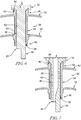
Fig. 3 is a diagrammatic and cross-sectional view of a portion of the turbine vane assembly ofFig. 2 showing that the turbine vane assembly includes the metallic support strut, the ceramic matrix composite vane, and a low-friction sleeve located between the support strut and the vane to allow the vane to slide relative to the support strut in response to relative thermal growth between the components of the turbine vane assembly during operation of the gas turbine engine; -
Fig. 4 is an exploded view of the turbine vane assembly ofFig. 3 showing the metallic support strut, the ceramic matrix composite vane adapted to receive the metallic support strut in an interior region of the vane, and the low-friction sleeve adapted to extend around the metallic support strut; -
Fig. 5 is a view similar toFig. 3 showing that the low-friction sleeve is coupled to the support strut and engages directly with an inner surface of the vane to transmit force loads acting on the vane to the support strut while also allowing the inner surface of the vane to slide continuously and radially relative to the support strut; -
Fig. 6 is a diagrammatic and cross-sectional view of another embodiment the turbine vane assembly ofFig. 2 showing that the turbine vane assembly includes a support strut, a vane, and a sleeve integrally formed with the support strut; -
Fig. 7 is a diagrammatic and cross-sectional view of another embodiment of the turbine vane assembly ofFig. 2 not forming part of the invention and showing that the turbine vane assembly includes a support strut, a vane, and a sleeve integrally formed with the vane; -
Fig. 8 is a diagrammatic and cross-sectional view of another embodiment of the turbine vane assembly ofFig. 2 not forming part of the invention and showing that the turbine vane assembly includes a support strut, a vane, and a sleeve that is coupled with the vane for movement with the vane relative to the support strut; -
Fig. 9 is a diagrammatic and cross-sectional view of another embodiment of the turbine vane assembly ofFig. 2 not forming part of the invention showing that the turbine vane assembly includes a support strut, a vane, and a sleeve located at a radial outer end of the vane and that the support strut includes a radial inner mount panel to transfer load from the vane to the support strut at a radial inner end of the vane; -
Fig. 10 is an exploded view of another turbine vane assembly not forming part of the invention showing that the turbine vane assembly includes a support strut, a vane, and a sleeve coupled with the support strut and located between the support strut and the vane to allow the vane to slide relative to the support strut and showing that the low-friction sleeve defines a cutout that receives an anti-rotation tab of the vane to block rotation of the vane relative to the support strut; -
Fig. 11 is a diagrammatic and cross-sectional view of the turbine vane assembly ofFig. 10 showing that the low-friction sleeve is coupled to an inner mount panel of the support strut and engages directly with an outer surface of the vane to transmit force loads acting on the vane to the support strut; -
Fig. 12 is an exploded view of another turbine vane assembly in accordance with the present disclosure showing that the turbine vane assembly includes a support strut, a vane, and a plurality of sleeves to allow the vane to slide relative to the support strut and suggesting that a spar of the support strut includes retainer bands that block radial movement of the sleeve relative to the spar; -
Fig. 13 is a diagrammatic and cross-sectional view of the turbine vane assembly ofFig. 12 showing that one sleeve is located at a radial inner end of an airfoil of the vane and another sleeve is located at a radial outer end of the airfoil of the vane; -
Fig. 14 is an exploded view of another turbine vane assembly in accordance with the present disclosure showing that the turbine vane assembly includes a support strut, a vane, and a multi-piece sleeve and a sleeve formed to include a cutout that receives an anti-rotation tab included in the vane; -
Fig. 15 is a diagrammatic and cross-sectional view of the turbine vane assembly ofFig. 14 showing that an airfoil of the vane includes the anti-rotation tab that extends from the inner surface of the airfoil into the cutout formed in the radial outer sleeve to block rotation of the vane relative to the support strut; -
Fig. 16 is an exploded view of another embodiment of a turbine vane assembly in accordance with the present disclosure showing that the turbine vane assembly includes a support strut, a vane having a tapered end, and a plurality of sleeves to allow the vane to slide relative to the support strut and one of the sleeves engages the tapered end of the vane to limit radial movement of the vane in the radial inward direction; and -
Fig. 17 is a diagrammatic and cross-sectional view of the turbine vane assembly ofFig. 16 showing that an airfoil of the vane includes a radial inner end that is tapered away from the support strut and showing that one of the sleeves engages the tapered radial inner end of the airfoil to transmit force loads acting on the airfoil to a spar of the support strut and to limit radial movement of the vane in the radial inward direction. - For the purposes of promoting an understanding of the principles of the disclosure, reference will now be made to a number of illustrative embodiments illustrated in the drawings and specific language will be used to describe the same.
- A
turbine vane assembly 20 according to the present invention is adapted for use in agas turbine engine 10 as suggested inFigs. 1 and 2 . Thegas turbine engine 10 includes afan 12, acompressor 14, acombustor 16, and aturbine 18. Thefan 12 generates thrust for propelling an aircraft. Thecompressor 14 compresses and delivers air to thecombustor 16. Thecombustor 16 mixes fuel with the compressed air received from thecompressor 14 and ignites the fuel. The hot, high-pressure gases from the burning fuel are directed into theturbine 18 where theturbine 18 extracts work from the gases to drive thecompressor 14 and thefan 12. In other embodiments, thegas turbine engine 10 may include a shaft, turboprop, or gearbox in place of thefan 12. - The
turbine 18 includes a plurality ofturbine vane assemblies 20 andturbine wheel assemblies 22 as shown inFig. 1 . A portion of one of theturbine vane assemblies 20 is shown inFig. 2 . Theturbine vane assembly 20 extends partway about anaxis 11 of thegas turbine engine 10 and is located betweenturbine wheel assemblies 22 to direct gases received from an upstreamturbine wheel assembly 22 toward a downstreamturbine wheel assembly 22. Eachturbine wheel assembly 22 is configured to interact with the hot combustion gases from thecombustor 16 and rotate about theaxis 11 of thegas turbine engine 10 to generate power for driving thecompressor 14 and/or thefan 12. - The
turbine vane assembly 20 includes asupport strut 24, avane 26, and asleeve 28 as shown inFigs. 3-5 . Thesupport strut 24 provides structural support for theturbine vane assembly 20 and may be mounted in a ring or to a turbine case of the turbine. Thevane 26 defines aprimary gas path 30 adapted to conduct hot gases through theturbine vane assembly 20 during use of theturbine vane assembly 20. Thevane 26 insulates thesupport strut 24 from the hot gases in theprimary gas path 30. Thesleeve 28 is located between thesupport strut 24 and thevane 26 and is made to be low-friction to allow thevane 26 to slide relative to thesupport strut 24 in response to thermal growth mismatch between thevane 26 and thesupport strut 24 caused by different coefficients of thermal expansion of thevane 26 and thesupport strut 24 during use of theturbine vane assembly 20. The sleeve further transmits force loads acting on thevane 26 to thesupport strut 24. - The
support strut 24 includes anouter mount panel 32, aspar 36, and amount extension 38 as shown inFig. 4 . Portions of theouter mount panel 32 are broken away to show only the radial inner portion of theouter mount panel 32. Theouter mount panel 32 is configured to couple theturbine vane assembly 20 with a casing of theturbine 18 for movement with the casing and to transmit loads acting on the turbine vane assembly to the casing. Thespar 36 extends radially-inwardly from theouter mount panel 32 relative to theaxis 11. In some embodiments, thespar 36 may be hollow with one or more cooling air impingement holes to allow cooling air from a secondary air system to flow through thespar 36 and cool the ceramic matrix composite material. Thespar 36 may also transit flow to feed other cavities with cooling air. Themount extension 38 extends radially-inwardly from thespar 36 relative to theaxis 11. In some embodiments, themount extension 38 may be mounted an inner seal. illustratively, thesupport strut 24 is made of metallic materials. - In illustrative embodiments, the
outer mount panel 32 is formed to define avane receiver 40 that extends radially outward into theouter mount panel 32 as shown inFig. 5 . Thevane receiver 40 receives a portion of thevane 26 to cause thevane 26 to engage theouter mount panel 32 and transmit circumferential and axial loads applied to thevane 26 to thesupport strut 24 at a radial outer end of thevane 26 outside of theprimary gas path 30 where the temperature of theturbine vane assembly 20 may be lower. - The
vane 26 includes anouter end wall 52, aninner end wall 54 spaced apart radially from theouter end wall 52 relative to theaxis 11, and anairfoil 56 as shown inFigs. 4 and5 . Theairfoil 56 extends radially between and interconnects theouter end wall 52 and theinner end wall 54. Theouter end wall 52 defines a radially outer boundary of theprimary gas path 30 and theinner end wall 54 defines a radially inner boundary of theprimary gas path 30. Theouter end wall 52 shields theouter mount panel 32 of thesupport strut 24 from theprimary gas path 30. Theairfoil 56 is shaped to redirect air flowing through thegas turbine engine 10 and shield thesupport strut 24 from theprimary gas path 30. - The
airfoil 56 includes a radialouter end 58, a radialinner end 60, aninner surface 62, and anouter surface 64 as shown inFigs. 4 and5 . The radialinner end 60 is spaced apart radially from the radialouter end 58 relative to theaxis 11 and extends radially-inwardly past theinner end wall 54 outside of theprimary gas path 30 in the illustrative embodiment. The radialouter end 58 extends radially-outwardly past theouter end wall 52 outside of theprimary gas path 30. Theinner surface 62 of theairfoil 56 defines acavity 65 that receives thespar 36 of thesupport strut 24. Theouter surface 64 is spaced apart from theinner surface 62 facing away from thecavity 65 and toward theprimary gas path 30. Theinner surface 62 is spaced apart from thespar 36 to form a gap therebetween. - The radial
outer end 58 of theairfoil 56 is shaped to form aload transfer tab 66 in the illustrative embodiment as shown inFig. 5 . Theload transfer tab 66 extends into thevane receiver 40 formed in thesupport strut 24 to transfer loads applied to thevane 26 to thesupport strut 24 at the radialouter end 58 of theairfoil 56. In other embodiments, the radialinner end 60 of theairfoil 56 is shaped to form theload transfer tab 66 as shown, for example, inFig. 9 . In some embodiments, one or more seals are located between theairfoil 56 and thespar 36. - In illustrative embodiments, the
vane 26 is made entirely from ceramic matrix composite materials. In the illustrative embodiment, theouter end wall 52, theinner end wall 54, and theairfoil 56 of thevane 26 are integrally formed from ceramic matrix composite materials such that theouter end wall 52, theinner end wall 54, and theairfoil 56 are a single, one-piece,integral vane component 26. In other embodiments, theouter end wall 52,inner end wall 54, and theairfoil 56 are formed as separate components. Thevane 26 has a first coefficient of thermal expansion and thesupport strut 24 has a second coefficient of thermal expansion different than the first coefficient of thermal expansion. - The
sleeve 28 is located between thespar 36 of thesupport strut 24 and theairfoil 56 of thevane 26 to allow thevane 26 to slide relative to thesupport strut 24 during use of theturbine vane assembly 20 as suggested inFig. 5 . In the illustrative embodiment, thesleeve 28 allows theinner surface 62 of theairfoil 56 to slide continuously and radially relative to thespar 36 in response to relative thermal growth between thesupport strut 24 and thevane 26 during use of theturbine vane assembly 20. Thesleeve 28 is continuous airfoil shaped when viewed radially relative to theaxis 11 in the embodiment shown inFigs. 4 and5 . In other embodiments, thesleeve 28 may be shaped as per the inner shape of theairfoil 56 or any other suitable alternative shape. In other embodiments, thesleeve 28 may be formed to include cutouts. In some embodiments, thesleeve 28 is formed from a plurality of discrete sleeve pieces as shown inFig. 15 . Theinner surface 62 of theairfoil 56 is continuous to allow sliding movement along thesleeve 28. - The
sleeve 28 is rigid (non-compliant) and directly engages theinner surface 62 of theairfoil 56 that faces thespar 36 to transmit force loads acting on theairfoil 56 to thespar 36. Therigid sleeve 28 may therefore be determinate and loading on thesleeve 28 may be predetermined. In other embodiments, the low-friction sleeve 28 transmits loads acting on theairfoil 56 to thespar 36 at the radialouter end 58 of theairfoil 56 as shown, for example, inFig. 9 . In some embodiments, theturbine vane assembly 20 includes a plurality ofsleeves 28 as shown inFig. 13 . - The
sleeve 28 includes anattachment surface 78 and acontact surface 80 as shown inFigs. 4 and5 . Theattachment surface 78 is coupled with thespar 36 and is shaped to match the profile of thespar 36 in the illustrative embodiment. Thecontact surface 80 engages theinner surface 62 of theairfoil 56. Thecontact surface 80 may engage directly theinner surface 62 of theairfoil 56. In the illustrative embodiment, thecontact surface 80 of thesleeve 28 is convex. The convex shape of thecontact surface 80 of thesleeve 28 allows the sleeve to transmit loads acting on theairfoil 56 to thespar 36 while also allowing thevane 26 to slide relative to thesupport strut 24 in response to thermal growth between thesupport strut 24 and thevane 26 during use of theturbine vane assembly 20. - In other embodiments, the attachment surface 82 is coupled with the
inner surface 62 of theairfoil 56 and is shaped to match the profile of the inner surface of theairfoil 56 as shown inFigs. 7 and8 . In such embodiments, the contact surface 84 engages thespar 36 and is convex to encourage sliding while enabling load transfer. - In the illustrative embodiment, the
sleeve 28 is made of silicon nitride and coupled to aspar 36 of thesupport strut 24 for movement therewith as shown inFig. 5 . In other embodiments, the low-friction sleeve 28 is made of other low-friction, high-temperature capable materials such as, for example, PM121, Ni3AI, or materials that naturally form lubricating oxide layers such as Ni-Cu-Re or Co-Cu-Re. Additionally, in other embodiments, the low-friction sleeve 28 may be made of metallic materials with a low-friction, diffusion barrier coating. The low-friction material of thesleeve 28 allows thevane 26 to slide relative to thesupport strut 24. Thesleeve 28 may be brazed, bonded, or integrally formed with thespar 36 orairfoil 56 or may be coupled therewith by any other suitable alternative. In some embodiments, thesleeve 28 includes a body and an outer diffusion barrier coat adhered to the body. - The
contact surface 80 of thesleeve 28 is polished in some embodiments to provide the relatively low-friction surface for sliding. In some embodiments, theinner surface 62 of theairfoil 56 is polished in some embodiments to provide a relatively low-friction surface for sliding. In some embodiments, theinner surface 62 of theairfoil 56 includes a coating to provide a relatively low-friction surface for sliding. Thecontact surface 80 of thesleeve 28 may have a surface roughness of about 0.80 µm (micrometer) Ra. In some embodiments, thecontact surface 80 has a roughness of at least about 1.6 µm (micrometer) Ra or less. In some embodiments, thecontact surface 80 of thesleeve 28 has a surface roughness of about 2 µm (micrometer) Ra or less. Thecontact surface 80 of thesleeve 28 may have a surface hardness of about 70 HRC to 100 HRC. In some embodiments, thecontact surface 80 of thesleeve 28 may have a surface hardness of between about 75 HRC and about 95 HRC. In some embodiments, thecontact surface 80 of thesleeve 28 may have a surface hardness of between about 80 HRC and about 90 HRC. In some embodiments, thecontact surface 80 of thesleeve 28 may have a surface hardness of about 78 HRC. In some embodiments, thecontact surface 80 of thesleeve 28 may have a surface hardness of about 90 HRC. - In other embodiments, the
sleeve 28 may be made from ceramic matrix composite material. The ceramic matrix material may then be machined to a much improved or desired roughness value and/or coated with an environmental barrier coating. - During operation of the
gas turbine engine 10, thesupport strut 24 and thevane 26 are heated from the gases in thegas path 30. Thesupport strut 24 and thevane 26 grow radially relative to one another due to their different coefficients of thermal expansion. Thesleeve 28 provides a relative low-friction surface (as compared to the surface of thespar 36 or a seal) to allow thevane 26 to freely translate radially relative to thesupport strut 24 to reduce stresses acting on the ceramic matrixcomposite vane 26. Additionally, thesleeve 28 is rigid and transmits loads acting on thevane 26 to thesupport strut 24. - At engine overhaul, the
sleeve 28 may be replaced while theoriginal spar 36 andvane 26 are reused in theengine 10. In other instances, theentire assembly 20 may be replaced. - In the illustrative embodiment shown in
Fig. 5 , the radialouter end 58 of theairfoil 56 is engaged with theouter mount panel 32 of thesupport strut 24. As a result, thespar 36 may grow (slide or translate) radially inward relative toairfoil 56 to cause thesleeve 28 to slide along theairfoil 56. In any case, it can be considered that relative movement is made between thevane 26 and thesupport strut 24 due to thermal growth of the components. - In some embodiments, the
sleeve 28 and thesupport strut 24 are integrally formed as a single, one-piece, unitary component as shown inFig. 6 . In other examples falling outside of the scope of the invention, the low-friction sleeve 28 and thevane 26 may be integrally formed as a single, one-piece, unitary component as shown inFig. 7 . In another unclaimed illustrative example, the low-friction sleeve 28 may be made of ceramic matrix composite materials and coupled to theinner surface 62 of thevane 26 as shown inFig. 8 . - In some embodiments, the
support strut 24 further includes aninner mount panel 34 as shown inFig. 9 . Theinner mount panel 34 is spaced apart radially from theouter mount panel 32. Thespar 36 extends between and interconnects theinner mount panel 34 and theouter mount panel 32. In the embodiment ofFig. 9 , theinner mount panel 34 is shaped to include theload vane receiver 40. Thevane receiver 40 is formed in a radial inward side of theinner mount panel 34 outside of theprimary gas path 30. In such an embodiment, the radialouter end 58 of theairfoil 56 may be spaced apart from theouter mount panel 32. Thesleeve 28 is located at the radialouter end 58 of theairfoil 56. - Another embodiment of a
turbine vane assembly 220 not forming part of the invention is shown inFigs. 10 and 11 . Theturbine vane assembly 220 is substantially similar to theturbine vane assembly 20 shown inFigs. 1-5 and described herein. Accordingly, similar reference numbers in the 200 series indicate features that are common between theturbine vane assembly 20 and theturbine vane assembly 220. The description of theturbine vane assembly 20 is incorporated by reference to apply to theturbine vane assembly 220, except in instances when it conflicts with the specific description and the drawings of theturbine vane assembly 220. - The
turbine vane assembly 220 includes asupport strut 224, avane 226, and asleeve 228 as shown inFigs. 10 and 11 . Thesupport strut 224 includes anouter mount panel 232, aninner mount panel 234, aspar 236, and amount extension 238 as shown inFigs. 10 and 11 . Theinner mount panel 234 is spaced apart radially from theouter mount panel 232. Thespar 236 extends radially between theouter mount panel 232 and theinner mount panel 234. Themount extension 238 extends radially-inwardly from thespar 236 relative to theaxis 11. - The
inner mount panel 234 includes apanel 242 and arim 244 as shown inFigs. 10 and 11 . Therim 244 extends radially-inwardly away from thepanel 242 relative to theaxis 11 to define achannel 245 between an inner surface of therim 244 and the outer surface of thespar 236. In the illustrative embodiment, therim 244 is airfoil shaped. - The
vane 226 includes anouter end wall 252, aninner end wall 254, and anairfoil 256 as shown inFigs. 10 and 11 . Theairfoil 256 includes a radialouter end 258 and a radialinner end 260. The radialinner end 260 is spaced apart radially from the radialouter end 258. The radialinner end 260 of theairfoil 256 extends radially-inwardly past theinner end wall 254 outside of theprimary gas path 30 into thechannel 245 formed by theinner mount panel 234 to be engaged by thesleeve 228. The radialouter end 258 extends radially-outwardly past theouter end wall 252 outside of theprimary gas path 30. - The radial
inner end 260 is shaped to include ananti-rotation tab 276 as shown inFig. 11 . Theanti-rotation tab 276 extends away from anouter surface 264 of theairfoil 256 toward therim 244 of thesupport strut 224. Theanti-rotation tab 276 extends into acutout 286 formed in the low-friction sleeve 228 to block rotation of thevane 226 relative to thesupport strut 224. - The low-
friction sleeve 228 is located between therim 244 of theinner mount panel 234 of thesupport strut 224 and theairfoil 256 of thevane 226 in thechannel 245 to allow thevane 226 to slide relative to thesupport strut 224. Thesleeve 228 is rigid and engages theouter surface 264 of theairfoil 256 that faces therim 244 of theinner mount panel 234 to transmit force loads acting on theairfoil 256 to thesupport strut 224 at the radialinner end 260 of theairfoil 256. Thesleeve 228 allows theouter surface 264 of theairfoil 256 to slide continuously and radially relative to thesupport strut 224 in response to relative thermal growth between thesupport strut 224 and thevane 226 during use of theturbine vane assembly 220. - The low-
friction sleeve 228 includes a body that has anattachment surface 278, acontact surface 280, afirst end 282, and asecond end 284 as shown inFigs. 11 and12 . Theattachment surface 278 is coupled with the inner surface of therim 244 and is shaped to match the profile of therim 244. Thecontact surface 280 engages directly theouter surface 264 of theairfoil 256. In the illustrative embodiment, thecontact surface 280 of the body of thesleeve 228 is convex. The convex shape of thecontact surface 280 of thesleeve 228 allows the sleeve to transmit loads acting on theairfoil 256 to thespar 236 while also allowing thevane 226 to slide relative to thesupport strut 224 in response to thermal growth between thesupport strut 224 and thevane 226 during use of theturbine vane assembly 220. Thesecond end 284 is spaced apart from thefirst end 282 to define acutout 286 that extends radially through thesleeve 228. - In the illustrative embodiment, the
sleeve 228 further includes aseparate insert 288 as shown inFigs. 10 and 11 . Theinsert 288 is located in thecutout 286 of the body of thesleeve 228 and engages theanti-rotation tab 276 of the radialinner end 260 of theairfoil 256. The insert has a smaller thickness than the portion of thesleeve 28 that extends between the first and second ends 282, 284 so that it fits between theinner mount panel 234 and theanti-rotation tab 276. - The
insert 288 is shaped to include anattachment surface 290 and acontact surface 292 as shown inFigs. 10 and 11 . Theattachment surface 290 is coupled with the inner surface of therim 244 and is shaped to match the profile of therim 244. Thecontact surface 292 engages theouter surface 264 of theairfoil 256 at theanti-rotation tab 276. In the illustrative embodiment, thecontact surface 292 of thesleeve 228 is convex. The curvature of theconvex contact surface 292 of therib 288 is less than the curvature of thecontact surface 280. - Another embodiment of a
turbine vane assembly 320 in accordance with the present invention is shown inFigs. 12 and 13 . Theturbine vane assembly 320 is substantially similar to theturbine vane assembly 20 shown inFigs. 1-5 and described herein. Accordingly, similar reference numbers in the 300 series indicate features that are common between theturbine vane assembly 20 and theturbine vane assembly 320. The description of theturbine vane assembly 20 is incorporated by reference to apply to theturbine vane assembly 320, except in instances when it conflicts with the specific description and the drawings of theturbine vane assembly 320. - The
turbine vane assembly 320 includes asupport strut 324, avane 326, and a plurality ofsleeves 328 as shown inFigs. 12 and 13 . Thesupport strut 324 includes anouter mount panel 332, aspar 336, and amount extension 338. Thespar 336 extends radially-inwardly from theouter mount panel 332 relative to theaxis 11. Themount extension 338 extends radially-inwardly from thespar 336 relative to theaxis 11. - The
spar 336 includes abody 346,inner retainer bands 348, and anouter retainer band 350 as shown inFigs. 12 and 13 . Theinner retainer bands 348 are located at a radial inner end of thespar 336. Theouter retainer band 350 is spaced apart from theinner retainer bands 348 at an opposite end of thespar 336. The inner andouter retainer bands body 346 to block radial movement of thesleeve body 346 of thespar 336. - In the illustrative embodiment, the
retainer bands spar 336 and rigidly attached to thebody 346 of thespar 336 through i.e. welding, brazing, or any other suitable retention approach. In other embodiments, theretainer bands body 346 of thespar 336. - The plurality of
sleeves inner sleeve 328 and anouter sleeve 329 as shown inFigs. 12 and 13 . Theinner sleeve 328 is located between thespar 336 of thesupport strut 324 and anairfoil 356 of thevane 326 at a radialinner end 360 of theairfoil 356. Theouter sleeve 329 is located between thespar 336 and theairfoil 356 of thevane 326 at a radialouter end 358 of theairfoil 356. The inner andouter sleeves vane 326 to slide relative to thesupport strut 324. Thesleeves inner surface 362 of theairfoil 356 that faces thespar 336 to transmit force loads acting on theairfoil 356 to thespar 336. Thesleeves inner surface 362 of theairfoil 356 to slide continuously and radially relative to thespar 336 in response to relative thermal growth between thesupport strut 324 and thevane 326 during use of theturbine vane assembly 320. - In the illustrative embodiment, the
inner sleeve 328 is located between theinner retainer bands 348 of thespar 336. Theouter sleeve 329 is located between theouter mount plate 332 and theouter retainer band 350. Thesleeves spar 336 and are retained in position by thebands sleeves spar 336 orairfoil 356. - Each of the
sleeves attachment surface 378 and acontact surface 380 as shown inFigs. 12 and 13 . Theattachment surface 378 is coupled with thespar 336. Thecontact surface 380 engages directly theinner surface 362 of theairfoil 356. In the illustrative embodiment, thecontact surface 380 of thesleeves contact surface 380 of thesleeve 328 allows the sleeve to transmit loads acting on theairfoil 356 to thespar 336 while also allowing thevane 326 to slide relative to thesupport strut 324 in response to thermal growth between thesupport strut 324 and thevane 326 during use of theturbine vane assembly 320. - Another embodiment of a
turbine vane assembly 420 in accordance with the present invention is shown inFigs. 14 and 15 . Theturbine vane assembly 420 is substantially similar to theturbine vane assembly 20 shown inFigs. 1-5 and described herein. Accordingly, similar reference numbers in the 400 series indicate features that are common between theturbine vane assembly 20 and theturbine vane assembly 420. The description of theturbine vane assembly 20 is incorporated by reference to apply to theturbine vane assembly 420, except in instances when it conflicts with the specific description and the drawings of theturbine vane assembly 420. - The
turbine vane assembly 420 includes asupport strut 424, avane 426, and a plurality ofsleeves Figs. 14 and 15 . Thesupport strut 424 includes anouter mount panel 432, aspar 436, and amount extension 438. Thespar 436 extends radially-inwardly from theouter mount panel 432 relative to theaxis 11. Themount extension 438 extends radially-inwardly from thespar 436 relative to theaxis 11. - The
vane 426 includes anouter end wall 452, aninner end wall 454, and anairfoil 456 as shown inFigs. 14 and 15 . Theairfoil 456 extends between and interconnects theouter end wall 452 and theinner end wall 454. Theouter end wall 452 defines a radially outer boundary of theprimary gas path 30 and theinner end wall 454 defines a radially inner boundary of theprimary gas path 30. Theouter end wall 452 shields theouter mount panel 432 of thesupport strut 424 from theprimary gas path 30. Theairfoil 456 is shaped to redirect air flowing through thegas turbine engine 10 and shield thespar 436 of thesupport strut 424 from theprimary gas path 30. - The
airfoil 456 includes a radialouter end 458, a radialinner end 460, aninner surface 462, and anouter surface 464 as shown inFigs. 14 and 15 . The radialinner end 460 is spaced apart radially from the radialouter end 458 and extends radially-inwardly past theinner end wall 454 outside of theprimary gas path 30. The radialouter end 458 extends radially-outwardly past theouter end wall 452 outside of theprimary gas path 30. Theinner surface 462 of theairfoil 456 defines acavity 465 that receives thespar 436 of thesupport strut 424. Theouter surface 464 is spaced apart from theinner surface 462 facing away from thecavity 465 and toward theprimary gas path 30. - The
airfoil 456 further includes apressure side wall 468, asuction side wall 470, and ananti-rotation tab 476 as shown inFigs. 14 and 15 . Thepressure side wall 468 and asuction side wall 470 spaced apart circumferentially from thepressure side wall 468. Thepressure side wall 468 and thesuction side 470 extend axially between and interconnect a leading edge and a trailing edge of theairfoil 458. Theanti-rotation tab 476 extends away from thesuction side wall 470 toward thespar 436 in the illustrative embodiment. In other embodiments, theanti-rotation tab 476 may extend from thepressure side wall 468. In the illustrative embodiment, theairfoil 456 includes an inner and outeranti-rotation tabs 476 that extend from thesuction side wall 470 at the radial outer andinner end airfoil 456. - The plurality of
sleeves inner sleeve 428 and an outer 429 sleeve as shown inFigs. 14 and 15 . Theinner sleeve 428 is located between thespar 436 of thesupport strut 424 and theairfoil 456 of thevane 426 at the radialinner end 460 of theairfoil 456. Theouter sleeve 429 is located between thespar 436 and theairfoil 456 of thevane 426 at the radialouter end 458 of theairfoil 456. Thesleeves vane 426 to slide relative to thesupport strut 424. Thesleeves inner surface 462 of theairfoil 456 that faces thespar 436 to transmit force loads acting on theairfoil 456 to thespar 436. Thesleeves inner surface 462 of theairfoil 456 to slide continuously and radially relative to thespar 436 in response to relative thermal growth between thesupport strut 424 and thevane 426 during use of theturbine vane assembly 420. - Each of the
sleeves Fig. 14 and 15 . The attachment surface 478 is coupled with thespar 436 of thesupport strut 424 and is shaped to match the profile of thespar 436. The contact surface 480 engages theouter surface 464 of theairfoil 456. In the illustrative embodiment, the contact surface 480 of thesleeve 428 is convex. The convex shape of the contact surface 480 of thesleeve 428 allows the sleeve to transmit loads acting on theairfoil 456 to thespar 436 while also allowing thevane 426 to slide relative to thesupport strut 424 in response to thermal growth between thesupport strut 424 and thevane 426 during use of theturbine vane assembly 420. In other embodiments, thesleeves airfoil 456. - The
inner sleeve 428 includes a plurality ofdiscrete ribs 488 as shown inFigs. 14 and 15 . Each of the plurality ofribs 488 is spaced apart from and aligned radially with aneighboring rib 488 included in the plurality ofribs 488. Theribs 488 are coupled with thespar 436 for movement therewith.Cutouts 486 are defined by the spaces between theribs 488. Theanti-rotation tab 476 of theairfoil 456 located at the radialinner end 460 of theairfoil 456 extends into one of thecutouts 486 defined between theribs 488 to block rotation of thevane 426 relative to thesupport strut 424. Thecutouts 486 defined between theribs 488 may allow for cooling air to flow radially through the gap between theairfoil 456 and thespar 436. - The
outer sleeve 429 includes afirst end 482 and asecond end 484 as shown inFigs. 14 and 15 . Thesecond end 484 is spaced apart from thefirst end 482 to define acutout 486 that extends radially through thesleeve 428. Theanti-rotation tab 476 of theairfoil 456 located at the radialouter end 458 of theairfoil 456 extends into thecutout 486 defined in thesleeve 428 to block rotation of thevane 426 relative to thesupport strut 424. - Another embodiment of a
turbine vane assembly 520 in accordance with the present invention is shown inFigs. 16 and 17 . Theturbine vane assembly 520 is substantially similar to theturbine vane assembly 20 shown inFigs. 1-5 and described herein. Accordingly, similar reference numbers in the 500 series indicate features that are common between theturbine vane assembly 20 and theturbine vane assembly 520. The description of theturbine vane assembly 20 is incorporated by reference to apply to theturbine vane assembly 520, except in instances when it conflicts with the specific description and the drawings of theturbine vane assembly 520. - The
turbine vane assembly 520 includes asupport strut 524, avane 526, and a plurality ofsleeves Figs. 16 and 17 . Thesupport strut 524 includes anouter mount panel 532, aspar 536, and amount extension 538. Thevane 526 includes anouter end wall 552, aninner end wall 554, and anairfoil 556 as shown inFigs. 16 and 17 . Theairfoil 556 extends between and interconnects theouter end wall 552 and theinner end wall 554. - The
airfoil 556 includes a radialouter end 558, a radialinner end 560, aninner surface 562, and anouter surface 564 as shown inFigs. 16 and 17 . The radialinner end 560 is spaced apart radially from the radialouter end 558 and extends radially-inwardly past theinner end wall 554 outside of theprimary gas path 30. The radialouter end 558 extends radially-outwardly past theouter end wall 552 outside of theprimary gas path 30. Theinner surface 562 of theairfoil 556 defines acavity 565 that receives aspar 536 of thesupport strut 524. Theouter surface 564 is spaced apart from theinner surface 562 facing away from thecavity 565 and toward theprimary gas path 30. - The radial
inner end 560 is tapered away from thespar 536 in the illustrative embodiment. The tapered shape of the radialinner end 560 of theairfoil 556 pre-loads or compresses the ceramic matrixcomposite vane 526 at assembly which minimizes the tensile loading on thevane 526 during operation of thegas turbine engine 10. The tapered end may limit radial movement of theairfoil 556 relative to thespar 536 while allowing some radial sliding (translating) of theairfoil 556 relative to thespar 536. - The plurality of
sleeves inner sleeve 528 and an outer 529 sleeve as shown inFigs. 16 and 17 . Theinner sleeve 528 is located between thespar 536 of thesupport strut 524 and theairfoil 556 of thevane 526 at the radialinner end 560 of theairfoil 556. Theinner sleeve 528 engages the taperedinner end 560 of theairfoil 556. Theouter sleeve 529 is located between thespar 536 and theairfoil 556 of thevane 526 at the radialouter end 558 of theairfoil 556. Thesleeves vane 526 to slide relative to thesupport strut 524. Thesleeves inner surface 562 of theairfoil 556 that faces thespar 536 to transmit force loads acting on theairfoil 556 to thespar 536. Thesleeves inner surface 562 of theairfoil 556 to slide continuously and radially relative to thespar 536 in response to relative thermal growth between thesupport strut 524 and thevane 526 during use of theturbine vane assembly 520. - Each of the
sleeves attachment surface 578 and acontact surface 580 as shown inFig. 16 and 17 . Theattachment surface 578 is coupled with thespar 536 of thesupport strut 524 and is shaped to match the profile of thespar 536. Thecontact surface 580 engages directly theouter surface 564 of theairfoil 556. In the illustrative embodiment, thecontact surface 580 of thesleeve 528 is convex. The convex shape of thecontact surface 580 of thesleeve 528 allows the sleeve to transmit loads acting on theairfoil 556 to thespar 536 while also allowing thevane 526 to slide relative to thesupport strut 524 in response to thermal growth between thesupport strut 524 and thevane 526 during use of theturbine vane assembly 520. In other embodiments, thesleeves airfoil 556. - This present invention provides a turbine vane assembly that accounts for the relative thermal growth mismatch between a ceramic matrix composite airfoil and the metallic support structure through a low-friction sliding joint. In typical turbine vane assemblies, a spring or other compliant feature is used to account for the thermal growth mismatch.
- The load from high pressure nozzle guide vanes is transmitted outboard to the high pressure turbine casing. In metallic embodiments, the nozzle guide vane structure is supported on hooks and/or rails attached to the outer platform. The hook and/or rail support structures provide a significant challenge for strain-limited structures manufactured from SiC/SiC ceramic matrix composite materials.
- In the illustrative embodiments, the aerodynamic loading is transferred at both the inner and outer extents of the vane. The load would typically transmit through a metallic structure or spar out into the casing. However, the ceramic matrix composite material has a significantly lower coefficient of thermal expansion compared to the high temperature metals. As such, there is a significant mismatch in radial height between cold build and the hottest operating conditions.
- The present invention aims to provide a solution to the alpha growth mismatch by employing a low-friction sliding contact at the load transfer feature. The aerodynamic load is transmitted through the contact while allowing radial growth. The aerodynamic load may be axial and/or circumferential. The sliding contact may be made with a silicon nitride sleeve attached to the metallic spar by brazing or other suitable attachment methods. Other low-friction, high-temperature capable materials such as PM212, Ni3AI, or materials that naturally form lubricating oxide layers such as Ni-Cu-Re or Co-Cu-Re may be used for the sliding contact. Silicon nitride is preferred due to the chemical compatibility with the SiC/SiC ceramic matrix composite material, but in lower temperature regions, metallic materials could have an optional low-friction, diffusion barrier coating.
- In some embodiments, the material of the sleeve may have a roughness value, or Ra value, of about 0.80 µm, but should have a roughness value of at least 1.6 µm. The material of the sleeve may also have a higher hardness value to combat wear. For example, SiC is approximately 90 HRC and Si3N4 is approximately 78 HRC.
- In the illustrative embodiments, a sliding contact is integrated onto the metallic spar and utilization of a compliant coating is used to protect the low strength ceramic matrix composite component. The sliding joint may be located at the inner platform as shown in
Figs. 5-8 or the outer platform as shown inFig. 9 . The sliding joint may be located at the outer platform if the net radial load on the ceramic matrix composite is inwards, rather than outwards. Alternatively, the sliding feature could be an integral part of the spar structure as shown inFig. 6 , rather than two separate features joined together. A single integral structure may alleviate concerns about the joint integrity, but would limit the choice of suitable spar materials. - In other embodiments, an inner platform engagement feature may be used to isolate the sliding joint from the ceramic matrix composite structure as shown in
Figs. 10 and 11 . The inner platform engagement feature could be replaced at engine overhaul to prolong the usable life of the expensive ceramic matrix composite structure. The inner platform engagement feature may maximize the size of the metallic spar which is important to reduce stresses. The inner platform may also improve the assembly and durability of the configuration by fabricating the metallic support structure around the ceramic matrix composite vane which may help retain the ceramic matrix composite structure in case of failure of the primary load transfer features. - In the illustrative embodiment, the sliding feature is rigid and includes an anti-rotation feature, thus controlling the position and rotation of the ceramic matrix composite vane, which is beneficial as the temperature and stress in the ceramic matrix composite material is sensitive to the angle that the hot gas impinges on the airfoil. Additionally, controlling the position and rotation of the vane is also beneficial, as any rotation of the airfoil will affect the turbine throat area or capacity, which changes the engine performance. The action of the sliding feature is may be predictable, meaning the wear rate, deterioration, and life of the feature may have lower risk/less uncertainty as compared to a deformable sleeve.
- In the illustrative embodiment, the sliding feature is spherically profiled to result in a more determinate transfer of loading. In other embodiments, the sliding feature may have other profiles such as an elongated rounded shape. The elongated rounded shape would minimize an increase in contact area with the ceramic matrix composite vane as the peak of the rounded shape wears away and therefore minimizing an increase in radial loading due to friction.
- The spherically profiled sliding feature may be applied at both radial inner and outer arrangements as shown in
Figs. 12-17 . In other examples, the sliding feature may be applied at both inner and outer arrangements within the airfoil structure itself like inFig. 7 . Applying the sliding feature within the airfoil simplifies the metallic support structure at the outer platform compared to the datum design which requires circumferential/axial and radial load transfer as shown inFigs. 5-9 . Providing the sliding feature at both inner and outer arrangements, when combined with a similar radial load transfer feature, may eliminate the ceramic matrix composite to metal interfaces with associated adverse chemical interactions. - In other embodiments, metallic retention features may be applied to the spar as shown in
Fig. 12 and 13 . The metallic retention features would provide a redundant attachment approach or may even serve as the primary approach if assembled carefully. - In other embodiments, the low friction feature may be slotted as shown in
Figs. 14 and 15 . The slots in the low friction feature allow the assembly to tolerate any coefficient of thermal expansion mismatches between the feature and the metallic spar. - As such, the sliding sleeve may not have a sealing functionality. For example, a slotted or discrete segment sleeve would allow flow to pass. In contrast a seal minimizes flow. The sliding sleeve may work only with relative small contact area with the ceramic matrix composite components. For example, the sleeve has at least two points of contact at the sliding end and three at the non-sliding. In contrast a seal generally maximizes the contact area with a ceramic matrix composite components.
- In other embodiments, the sliding interface may be tapered as shown in
Figs. 16 and 17 . The tapered interface biases the assembly. The taper also pre-loads or compresses the ceramic matrix composite structure at assembly to minimize the tensile loading when heated. - The present application may provide a method for attachment and load transfer between coefficients of thermal expansion mismatched structures. The present invention may provide an opportunity to avoid ceramic matrix composite and metallic interface with its associated adverse chemical interactions.
- While the invention has been illustrated and described in detail in the foregoing drawings and description, the same is to be considered as exemplary and not restrictive in character, it being understood that only illustrative embodiments thereof have been shown and described and that all changes and modifications that come within the scope of the claims are desired to be protected.
Claims (10)
- A turbine vane assembly (20,220,320,420,520) for a gas turbine engine comprising
a support strut (24) made of metallic material and extending radially relative to an axis,
a vane (26) made of ceramic matrix composite material that includes an airfoil (56) arranged around the support strut (24), and
wherein the support strut (24) includes an outer mount panel (32) and a spar (36) that extends radially inward from the outer mount panel and the vane (26) defines a primary gas path adapted to conduct hot gases during use of the turbine vane assembly (220,520), the vane (26) includes a radially outer end wall (52) positioned adjacent the outer mount panel, to define an outer boundary of the primary gas path, a radially inner end wall (54) spaced apart radially from the radially outer end wall to define an inner boundary of the primary gas path, and the airfoil (56) that extends radially between and interconnects the radially outer end wall and the radially inner end wall, and arranged around the spar to shield the spar from the gases in the primary gas path, and wherein
the spar is configured to couple the turbine vane assembly (220,520) to a turbine case, and
wherein a sleeve (28) located between the support strut (24) and the airfoil (56) and the sleeve (28) engages the support strut (24) and the airfoil (56), and
wherein the sleeve (28) is rigid and includes an attachment surface (78) coupled with the spar and a contact surface (80) that engages an inner surface (62) of the airfoil (56) to transmit force loads acting on the airfoil (56) to the spar and to allow the inner surface of the airfoil (56) to slide continuously and radially relative to the spar in response to relative thermal growth between the spar and the vane (26) during use of the turbine vane assembly (220,520), the attachment surface is shaped to match a contour of the spar, and the contact surface is convex, and; wherein the sleeve (28) is located radially at a radial inner end (60) of the airfoil (56). - The turbine vane assembly (220,420) of claim 1, wherein the sleeve (28) includes a body having a first end (282,482) and a second end (284,484) spaced apart from the first end to define a cutout (286,486) that extends radially through the body.
- The turbine vane assembly (220,420) of claim 2, wherein the airfoil (56) includes an anti-rotation feature (276,476) located in the cutout defined by the sleeve (28).
- The turbine vane assembly (220,420) of claim 3, wherein the sleeve (28) further includes an insert (288) located in the cutout and engaged with the support strut (24) and the anti-rotation feature of the airfoil (56).
- The turbine vane assembly (320,520) of any preceding claim, wherein the spar includes a body (346) and a retainer band (348,350) that extends away from the body and supports the sleeve (28) to block radial movement of the sleeve (28) relative to the body of the spar.
- The turbine vane assembly (220,420) of any preceding claim, wherein the sleeve (28) includes a plurality of discrete ribs (488) and each of the plurality of discrete ribs is spaced apart from and aligned radially with a neighboring one of the plurality of discrete ribs.
- The turbine vane assembly (220,520) of any one of claims 1-6, wherein the sleeve (28) and the support strut (24) are integrally formed as a single, one-piece component.
- The turbine vane assembly (220,520) of any preceding claim, wherein the airfoil (56) includes a radial first end and a radial second end that is spaced apart radially from the radial first end, the radial second end is tapered away from the support strut (24), and the sleeve (28) engages the radial second end.
- The turbine vane assembly (220,520) of any preceding claim, wherein the sleeve (28) is made of silicon nitride.
- The turbine vane assembly (220,520) of any preceding claim, wherein the sleeve (28) includes a body and an outer diffusion barrier coat adhered to the body.
Applications Claiming Priority (1)
| Application Number | Priority Date | Filing Date | Title |
|---|---|---|---|
| US16/227,617 US11149568B2 (en) | 2018-12-20 | 2018-12-20 | Sliding ceramic matrix composite vane assembly for gas turbine engines |
Publications (2)
| Publication Number | Publication Date |
|---|---|
| EP3670842A1 EP3670842A1 (en) | 2020-06-24 |
| EP3670842B1 true EP3670842B1 (en) | 2021-08-25 |
Family
ID=68808191
Family Applications (1)
| Application Number | Title | Priority Date | Filing Date |
|---|---|---|---|
| EP19214144.8A Active EP3670842B1 (en) | 2018-12-20 | 2019-12-06 | Sliding ceramic matrix composite vane assembly for gas turbine engines |
Country Status (2)
| Country | Link |
|---|---|
| US (1) | US11149568B2 (en) |
| EP (1) | EP3670842B1 (en) |
Families Citing this family (9)
| Publication number | Priority date | Publication date | Assignee | Title |
|---|---|---|---|---|
| US10851658B2 (en) * | 2017-02-06 | 2020-12-01 | General Electric Company | Nozzle assembly and method for forming nozzle assembly |
| US11149568B2 (en) * | 2018-12-20 | 2021-10-19 | Rolls-Royce Plc | Sliding ceramic matrix composite vane assembly for gas turbine engines |
| FR3102795B1 (en) * | 2019-10-31 | 2022-06-17 | Safran Aircraft Engines | Turbomachine turbine with CMC distributor with force take-up |
| US11448075B2 (en) * | 2020-11-02 | 2022-09-20 | Raytheon Technologies Corporation | CMC vane arc segment with cantilevered spar |
| US11536148B2 (en) * | 2020-11-24 | 2022-12-27 | Raytheon Technologies Corporation | Vane arc segment with thermal insulation element |
| US11668200B2 (en) | 2021-01-15 | 2023-06-06 | Raytheon Technologies Corporation | Vane with pin mount and anti-rotation |
| US11549385B2 (en) * | 2021-05-04 | 2023-01-10 | Raytheon Technologies Corporation | Airfoil assembly with seal plate and seal |
| US11814989B2 (en) * | 2021-10-29 | 2023-11-14 | Pratt & Whitney Canada Corp. | Vane array structure for a hot section of a gas turbine engine |
| US11913348B1 (en) | 2022-10-12 | 2024-02-27 | Rtx Corporation | Gas turbine engine vane and spar combination with variable air flow path |
Family Cites Families (39)
| Publication number | Priority date | Publication date | Assignee | Title |
|---|---|---|---|---|
| US3700348A (en) * | 1968-08-13 | 1972-10-24 | Gen Electric | Turbomachinery blade structure |
| US4519745A (en) * | 1980-09-19 | 1985-05-28 | Rockwell International Corporation | Rotor blade and stator vane using ceramic shell |
| US5284011A (en) | 1992-12-14 | 1994-02-08 | General Electric Company | Damped turbine engine frame |
| US5630700A (en) | 1996-04-26 | 1997-05-20 | General Electric Company | Floating vane turbine nozzle |
| US6325593B1 (en) | 2000-02-18 | 2001-12-04 | General Electric Company | Ceramic turbine airfoils with cooled trailing edge blocks |
| US6558114B1 (en) | 2000-09-29 | 2003-05-06 | Siemens Westinghouse Power Corporation | Gas turbine with baffle reducing hot gas ingress into interstage disc cavity |
| US6514046B1 (en) * | 2000-09-29 | 2003-02-04 | Siemens Westinghouse Power Corporation | Ceramic composite vane with metallic substructure |
| US6464456B2 (en) | 2001-03-07 | 2002-10-15 | General Electric Company | Turbine vane assembly including a low ductility vane |
| US6648597B1 (en) | 2002-05-31 | 2003-11-18 | Siemens Westinghouse Power Corporation | Ceramic matrix composite turbine vane |
| GB2402717B (en) | 2003-06-10 | 2006-05-10 | Rolls Royce Plc | A vane assembly for a gas turbine engine |
| US7745022B2 (en) * | 2005-07-22 | 2010-06-29 | Siemens Energy, Inc. | CMC with multiple matrix phases separated by diffusion barrier |
| US7452189B2 (en) | 2006-05-03 | 2008-11-18 | United Technologies Corporation | Ceramic matrix composite turbine engine vane |
| US7762766B2 (en) | 2006-07-06 | 2010-07-27 | Siemens Energy, Inc. | Cantilevered framework support for turbine vane |
| US7824152B2 (en) | 2007-05-09 | 2010-11-02 | Siemens Energy, Inc. | Multivane segment mounting arrangement for a gas turbine |
| US8210803B2 (en) | 2007-06-28 | 2012-07-03 | United Technologies Corporation | Ceramic matrix composite turbine engine vane |
| US8251652B2 (en) | 2008-09-18 | 2012-08-28 | Siemens Energy, Inc. | Gas turbine vane platform element |
| US8956105B2 (en) | 2008-12-31 | 2015-02-17 | Rolls-Royce North American Technologies, Inc. | Turbine vane for gas turbine engine |
| US8454303B2 (en) | 2010-01-14 | 2013-06-04 | General Electric Company | Turbine nozzle assembly |
| FR2974593B1 (en) | 2011-04-28 | 2015-11-13 | Snecma | TURBINE ENGINE COMPRISING A METAL PROTECTION OF A COMPOSITE PIECE |
| US9335051B2 (en) | 2011-07-13 | 2016-05-10 | United Technologies Corporation | Ceramic matrix composite combustor vane ring assembly |
| US9097141B2 (en) | 2011-09-15 | 2015-08-04 | Pratt & Whitney Canada Corp. | Axial bolting arrangement for mid turbine frame |
| US9546557B2 (en) | 2012-06-29 | 2017-01-17 | General Electric Company | Nozzle, a nozzle hanger, and a ceramic to metal attachment system |
| US20140255174A1 (en) | 2012-12-21 | 2014-09-11 | United Technologies Corporation | Manufacture of full ring strut vane pack |
| WO2014133721A1 (en) | 2013-02-27 | 2014-09-04 | United Technologies Corporation | Gas turbine engine thin wall composite vane airfoil |
| EP3009608B1 (en) | 2014-10-02 | 2019-10-30 | United Technologies Corporation | Vane assembly with trapped segmented vane structures |
| US10094239B2 (en) | 2014-10-31 | 2018-10-09 | Rolls-Royce North American Technologies Inc. | Vane assembly for a gas turbine engine |
| US9970317B2 (en) | 2014-10-31 | 2018-05-15 | Rolls-Royce North America Technologies Inc. | Vane assembly for a gas turbine engine |
| US9915159B2 (en) | 2014-12-18 | 2018-03-13 | General Electric Company | Ceramic matrix composite nozzle mounted with a strut and concepts thereof |
| US9863260B2 (en) | 2015-03-30 | 2018-01-09 | General Electric Company | Hybrid nozzle segment assemblies for a gas turbine engine |
| US10309240B2 (en) | 2015-07-24 | 2019-06-04 | General Electric Company | Method and system for interfacing a ceramic matrix composite component to a metallic component |
| US20170051619A1 (en) | 2015-08-18 | 2017-02-23 | General Electric Company | Cmc nozzles with split endwalls for gas turbine engines |
| US10273818B2 (en) | 2016-04-15 | 2019-04-30 | Rolls-Royce North American Technologies Inc. | Gas turbine engine with compliant layer for turbine vane assemblies |
| US10794289B2 (en) | 2016-08-09 | 2020-10-06 | General Electric Company | Modulated turbine component cooling |
| US10851658B2 (en) | 2017-02-06 | 2020-12-01 | General Electric Company | Nozzle assembly and method for forming nozzle assembly |
| US20180328187A1 (en) | 2017-05-09 | 2018-11-15 | General Electric Company | Turbine engine with an airfoil and insert |
| US10458260B2 (en) | 2017-05-24 | 2019-10-29 | General Electric Company | Nozzle airfoil decoupled from and attached outside of flow path boundary |
| US10569481B2 (en) | 2017-06-26 | 2020-02-25 | General Electric Company | Shaped composite ply layups and methods for shaping composite ply layups |
| US11802486B2 (en) * | 2017-11-13 | 2023-10-31 | General Electric Company | CMC component and fabrication using mechanical joints |
| US11149568B2 (en) * | 2018-12-20 | 2021-10-19 | Rolls-Royce Plc | Sliding ceramic matrix composite vane assembly for gas turbine engines |
-
2018
- 2018-12-20 US US16/227,617 patent/US11149568B2/en active Active
-
2019
- 2019-12-06 EP EP19214144.8A patent/EP3670842B1/en active Active
Also Published As
| Publication number | Publication date |
|---|---|
| EP3670842A1 (en) | 2020-06-24 |
| US20200200023A1 (en) | 2020-06-25 |
| US11149568B2 (en) | 2021-10-19 |
Similar Documents
| Publication | Publication Date | Title |
|---|---|---|
| EP3670842B1 (en) | Sliding ceramic matrix composite vane assembly for gas turbine engines | |
| US10890076B1 (en) | Turbine vane assembly having ceramic matrix composite components with expandable spar support | |
| US10767495B2 (en) | Turbine vane assembly with cooling feature | |
| US10995627B2 (en) | Turbine shroud with forward case and full hoop blade track | |
| US10808560B2 (en) | Turbine vane assembly with ceramic matrix composite components | |
| US11008888B2 (en) | Turbine vane assembly with ceramic matrix composite components | |
| US10934868B2 (en) | Turbine vane assembly with variable position support | |
| EP3739167B1 (en) | Turbine vane assembly having ceramic matrix composite components with sliding support | |
| EP3670843B1 (en) | Turbine section of a gas turbine engine with ceramic matrix composite vanes | |
| US10975709B1 (en) | Turbine vane assembly with ceramic matrix composite components and sliding support | |
| US11047247B2 (en) | Turbine section of a gas turbine engine with ceramic matrix composite vanes | |
| US11346234B2 (en) | Turbine vane assembly incorporating ceramic matrix composite materials | |
| US11378012B2 (en) | Insert-mounted turbine assembly for a gas turbine engine | |
| US10711621B1 (en) | Turbine vane assembly with ceramic matrix composite components and temperature management features | |
| EP3730738A1 (en) | Turbine assembly for a gas turbine engine with ceramic matrix composite vane | |
| US10954802B2 (en) | Turbine section assembly with ceramic matrix composite vane | |
| US11193393B2 (en) | Turbine section assembly with ceramic matrix composite vane | |
| US10883376B2 (en) | Turbine vane assembly with ceramic matrix composite vanes | |
| EP3819463B1 (en) | Turbine assembly with ceramic matrix composite components and interstage sealing features | |
| US10883371B1 (en) | Ceramic matrix composite vane with trailing edge radial cooling |
Legal Events
| Date | Code | Title | Description |
|---|---|---|---|
| PUAI | Public reference made under article 153(3) epc to a published international application that has entered the european phase |
Free format text: ORIGINAL CODE: 0009012 |
|
| STAA | Information on the status of an ep patent application or granted ep patent |
Free format text: STATUS: THE APPLICATION HAS BEEN PUBLISHED |
|
| AK | Designated contracting states |
Kind code of ref document: A1 Designated state(s): AL AT BE BG CH CY CZ DE DK EE ES FI FR GB GR HR HU IE IS IT LI LT LU LV MC MK MT NL NO PL PT RO RS SE SI SK SM TR |
|
| AX | Request for extension of the european patent |
Extension state: BA ME |
|
| STAA | Information on the status of an ep patent application or granted ep patent |
Free format text: STATUS: REQUEST FOR EXAMINATION WAS MADE |
|
| 17P | Request for examination filed |
Effective date: 20201222 |
|
| RBV | Designated contracting states (corrected) |
Designated state(s): AL AT BE BG CH CY CZ DE DK EE ES FI FR GB GR HR HU IE IS IT LI LT LU LV MC MK MT NL NO PL PT RO RS SE SI SK SM TR |
|
| RIC1 | Information provided on ipc code assigned before grant |
Ipc: F01D 9/04 20060101AFI20210219BHEP Ipc: F01D 5/28 20060101ALI20210219BHEP |
|
| GRAP | Despatch of communication of intention to grant a patent |
Free format text: ORIGINAL CODE: EPIDOSNIGR1 |
|
| STAA | Information on the status of an ep patent application or granted ep patent |
Free format text: STATUS: GRANT OF PATENT IS INTENDED |
|
| GRAS | Grant fee paid |
Free format text: ORIGINAL CODE: EPIDOSNIGR3 |
|
| GRAA | (expected) grant |
Free format text: ORIGINAL CODE: 0009210 |
|
| STAA | Information on the status of an ep patent application or granted ep patent |
Free format text: STATUS: THE PATENT HAS BEEN GRANTED |
|
| INTG | Intention to grant announced |
Effective date: 20210702 |
|
| AK | Designated contracting states |
Kind code of ref document: B1 Designated state(s): AL AT BE BG CH CY CZ DE DK EE ES FI FR GB GR HR HU IE IS IT LI LT LU LV MC MK MT NL NO PL PT RO RS SE SI SK SM TR |
|
| REG | Reference to a national code |
Ref country code: CH Ref legal event code: EP |
|
| REG | Reference to a national code |
Ref country code: IE Ref legal event code: FG4D Ref country code: AT Ref legal event code: REF Ref document number: 1423989 Country of ref document: AT Kind code of ref document: T Effective date: 20210915 |
|
| REG | Reference to a national code |
Ref country code: DE Ref legal event code: R096 Ref document number: 602019007175 Country of ref document: DE |
|
| REG | Reference to a national code |
Ref country code: LT Ref legal event code: MG9D |
|
| REG | Reference to a national code |
Ref country code: NL Ref legal event code: MP Effective date: 20210825 |
|
| REG | Reference to a national code |
Ref country code: AT Ref legal event code: MK05 Ref document number: 1423989 Country of ref document: AT Kind code of ref document: T Effective date: 20210825 |
|
| PG25 | Lapsed in a contracting state [announced via postgrant information from national office to epo] |
Ref country code: ES Free format text: LAPSE BECAUSE OF FAILURE TO SUBMIT A TRANSLATION OF THE DESCRIPTION OR TO PAY THE FEE WITHIN THE PRESCRIBED TIME-LIMIT Effective date: 20210825 Ref country code: RS Free format text: LAPSE BECAUSE OF FAILURE TO SUBMIT A TRANSLATION OF THE DESCRIPTION OR TO PAY THE FEE WITHIN THE PRESCRIBED TIME-LIMIT Effective date: 20210825 Ref country code: SE Free format text: LAPSE BECAUSE OF FAILURE TO SUBMIT A TRANSLATION OF THE DESCRIPTION OR TO PAY THE FEE WITHIN THE PRESCRIBED TIME-LIMIT Effective date: 20210825 Ref country code: LT Free format text: LAPSE BECAUSE OF FAILURE TO SUBMIT A TRANSLATION OF THE DESCRIPTION OR TO PAY THE FEE WITHIN THE PRESCRIBED TIME-LIMIT Effective date: 20210825 Ref country code: AT Free format text: LAPSE BECAUSE OF FAILURE TO SUBMIT A TRANSLATION OF THE DESCRIPTION OR TO PAY THE FEE WITHIN THE PRESCRIBED TIME-LIMIT Effective date: 20210825 Ref country code: BG Free format text: LAPSE BECAUSE OF FAILURE TO SUBMIT A TRANSLATION OF THE DESCRIPTION OR TO PAY THE FEE WITHIN THE PRESCRIBED TIME-LIMIT Effective date: 20211125 Ref country code: HR Free format text: LAPSE BECAUSE OF FAILURE TO SUBMIT A TRANSLATION OF THE DESCRIPTION OR TO PAY THE FEE WITHIN THE PRESCRIBED TIME-LIMIT Effective date: 20210825 Ref country code: FI Free format text: LAPSE BECAUSE OF FAILURE TO SUBMIT A TRANSLATION OF THE DESCRIPTION OR TO PAY THE FEE WITHIN THE PRESCRIBED TIME-LIMIT Effective date: 20210825 Ref country code: NO Free format text: LAPSE BECAUSE OF FAILURE TO SUBMIT A TRANSLATION OF THE DESCRIPTION OR TO PAY THE FEE WITHIN THE PRESCRIBED TIME-LIMIT Effective date: 20211125 Ref country code: PT Free format text: LAPSE BECAUSE OF FAILURE TO SUBMIT A TRANSLATION OF THE DESCRIPTION OR TO PAY THE FEE WITHIN THE PRESCRIBED TIME-LIMIT Effective date: 20211227 |
|
| PG25 | Lapsed in a contracting state [announced via postgrant information from national office to epo] |
Ref country code: PL Free format text: LAPSE BECAUSE OF FAILURE TO SUBMIT A TRANSLATION OF THE DESCRIPTION OR TO PAY THE FEE WITHIN THE PRESCRIBED TIME-LIMIT Effective date: 20210825 Ref country code: LV Free format text: LAPSE BECAUSE OF FAILURE TO SUBMIT A TRANSLATION OF THE DESCRIPTION OR TO PAY THE FEE WITHIN THE PRESCRIBED TIME-LIMIT Effective date: 20210825 Ref country code: GR Free format text: LAPSE BECAUSE OF FAILURE TO SUBMIT A TRANSLATION OF THE DESCRIPTION OR TO PAY THE FEE WITHIN THE PRESCRIBED TIME-LIMIT Effective date: 20211126 |
|
| PG25 | Lapsed in a contracting state [announced via postgrant information from national office to epo] |
Ref country code: NL Free format text: LAPSE BECAUSE OF FAILURE TO SUBMIT A TRANSLATION OF THE DESCRIPTION OR TO PAY THE FEE WITHIN THE PRESCRIBED TIME-LIMIT Effective date: 20210825 |
|
| PG25 | Lapsed in a contracting state [announced via postgrant information from national office to epo] |
Ref country code: DK Free format text: LAPSE BECAUSE OF FAILURE TO SUBMIT A TRANSLATION OF THE DESCRIPTION OR TO PAY THE FEE WITHIN THE PRESCRIBED TIME-LIMIT Effective date: 20210825 |
|
| REG | Reference to a national code |
Ref country code: DE Ref legal event code: R097 Ref document number: 602019007175 Country of ref document: DE |
|
| PG25 | Lapsed in a contracting state [announced via postgrant information from national office to epo] |
Ref country code: SM Free format text: LAPSE BECAUSE OF FAILURE TO SUBMIT A TRANSLATION OF THE DESCRIPTION OR TO PAY THE FEE WITHIN THE PRESCRIBED TIME-LIMIT Effective date: 20210825 Ref country code: SK Free format text: LAPSE BECAUSE OF FAILURE TO SUBMIT A TRANSLATION OF THE DESCRIPTION OR TO PAY THE FEE WITHIN THE PRESCRIBED TIME-LIMIT Effective date: 20210825 Ref country code: RO Free format text: LAPSE BECAUSE OF FAILURE TO SUBMIT A TRANSLATION OF THE DESCRIPTION OR TO PAY THE FEE WITHIN THE PRESCRIBED TIME-LIMIT Effective date: 20210825 Ref country code: EE Free format text: LAPSE BECAUSE OF FAILURE TO SUBMIT A TRANSLATION OF THE DESCRIPTION OR TO PAY THE FEE WITHIN THE PRESCRIBED TIME-LIMIT Effective date: 20210825 Ref country code: CZ Free format text: LAPSE BECAUSE OF FAILURE TO SUBMIT A TRANSLATION OF THE DESCRIPTION OR TO PAY THE FEE WITHIN THE PRESCRIBED TIME-LIMIT Effective date: 20210825 Ref country code: AL Free format text: LAPSE BECAUSE OF FAILURE TO SUBMIT A TRANSLATION OF THE DESCRIPTION OR TO PAY THE FEE WITHIN THE PRESCRIBED TIME-LIMIT Effective date: 20210825 |
|
| PLBE | No opposition filed within time limit |
Free format text: ORIGINAL CODE: 0009261 |
|
| STAA | Information on the status of an ep patent application or granted ep patent |
Free format text: STATUS: NO OPPOSITION FILED WITHIN TIME LIMIT |
|
| PG25 | Lapsed in a contracting state [announced via postgrant information from national office to epo] |
Ref country code: MC Free format text: LAPSE BECAUSE OF FAILURE TO SUBMIT A TRANSLATION OF THE DESCRIPTION OR TO PAY THE FEE WITHIN THE PRESCRIBED TIME-LIMIT Effective date: 20210825 Ref country code: IT Free format text: LAPSE BECAUSE OF FAILURE TO SUBMIT A TRANSLATION OF THE DESCRIPTION OR TO PAY THE FEE WITHIN THE PRESCRIBED TIME-LIMIT Effective date: 20210825 |
|
| 26N | No opposition filed |
Effective date: 20220527 |
|
| PG25 | Lapsed in a contracting state [announced via postgrant information from national office to epo] |
Ref country code: SI Free format text: LAPSE BECAUSE OF FAILURE TO SUBMIT A TRANSLATION OF THE DESCRIPTION OR TO PAY THE FEE WITHIN THE PRESCRIBED TIME-LIMIT Effective date: 20210825 |
|
| REG | Reference to a national code |
Ref country code: BE Ref legal event code: MM Effective date: 20211231 |
|
| PG25 | Lapsed in a contracting state [announced via postgrant information from national office to epo] |
Ref country code: LU Free format text: LAPSE BECAUSE OF NON-PAYMENT OF DUE FEES Effective date: 20211206 Ref country code: IE Free format text: LAPSE BECAUSE OF NON-PAYMENT OF DUE FEES Effective date: 20211206 |
|
| PG25 | Lapsed in a contracting state [announced via postgrant information from national office to epo] |
Ref country code: BE Free format text: LAPSE BECAUSE OF NON-PAYMENT OF DUE FEES Effective date: 20211231 |
|
| PGFP | Annual fee paid to national office [announced via postgrant information from national office to epo] |
Ref country code: DE Payment date: 20221227 Year of fee payment: 4 |
|
| PG25 | Lapsed in a contracting state [announced via postgrant information from national office to epo] |
Ref country code: CY Free format text: LAPSE BECAUSE OF FAILURE TO SUBMIT A TRANSLATION OF THE DESCRIPTION OR TO PAY THE FEE WITHIN THE PRESCRIBED TIME-LIMIT Effective date: 20210825 |
|
| P01 | Opt-out of the competence of the unified patent court (upc) registered |
Effective date: 20230528 |
|
| PG25 | Lapsed in a contracting state [announced via postgrant information from national office to epo] |
Ref country code: HU Free format text: LAPSE BECAUSE OF FAILURE TO SUBMIT A TRANSLATION OF THE DESCRIPTION OR TO PAY THE FEE WITHIN THE PRESCRIBED TIME-LIMIT; INVALID AB INITIO Effective date: 20191206 |
|
| REG | Reference to a national code |
Ref country code: CH Ref legal event code: PL |
|
| PG25 | Lapsed in a contracting state [announced via postgrant information from national office to epo] |
Ref country code: LI Free format text: LAPSE BECAUSE OF NON-PAYMENT OF DUE FEES Effective date: 20221231 Ref country code: CH Free format text: LAPSE BECAUSE OF NON-PAYMENT OF DUE FEES Effective date: 20221231 |
|
| PGFP | Annual fee paid to national office [announced via postgrant information from national office to epo] |
Ref country code: FR Payment date: 20231226 Year of fee payment: 5 |