EP3670835A1 - Gas turbine engine rotor blade with a local pressure side blade tip lean - Google Patents
Gas turbine engine rotor blade with a local pressure side blade tip lean Download PDFInfo
- Publication number
- EP3670835A1 EP3670835A1 EP19215014.2A EP19215014A EP3670835A1 EP 3670835 A1 EP3670835 A1 EP 3670835A1 EP 19215014 A EP19215014 A EP 19215014A EP 3670835 A1 EP3670835 A1 EP 3670835A1
- Authority
- EP
- European Patent Office
- Prior art keywords
- blade
- rotor
- rotor blade
- radial
- tip
- Prior art date
- Legal status (The legal status is an assumption and is not a legal conclusion. Google has not performed a legal analysis and makes no representation as to the accuracy of the status listed.)
- Pending
Links
Images

Classifications
-
- F—MECHANICAL ENGINEERING; LIGHTING; HEATING; WEAPONS; BLASTING
- F01—MACHINES OR ENGINES IN GENERAL; ENGINE PLANTS IN GENERAL; STEAM ENGINES
- F01D—NON-POSITIVE DISPLACEMENT MACHINES OR ENGINES, e.g. STEAM TURBINES
- F01D5/00—Blades; Blade-carrying members; Heating, heat-insulating, cooling or antivibration means on the blades or the members
- F01D5/12—Blades
- F01D5/14—Form or construction
- F01D5/141—Shape, i.e. outer, aerodynamic form
- F01D5/142—Shape, i.e. outer, aerodynamic form of the blades of successive rotor or stator blade-rows
-
- F—MECHANICAL ENGINEERING; LIGHTING; HEATING; WEAPONS; BLASTING
- F01—MACHINES OR ENGINES IN GENERAL; ENGINE PLANTS IN GENERAL; STEAM ENGINES
- F01D—NON-POSITIVE DISPLACEMENT MACHINES OR ENGINES, e.g. STEAM TURBINES
- F01D5/00—Blades; Blade-carrying members; Heating, heat-insulating, cooling or antivibration means on the blades or the members
- F01D5/12—Blades
- F01D5/14—Form or construction
- F01D5/141—Shape, i.e. outer, aerodynamic form
-
- F—MECHANICAL ENGINEERING; LIGHTING; HEATING; WEAPONS; BLASTING
- F01—MACHINES OR ENGINES IN GENERAL; ENGINE PLANTS IN GENERAL; STEAM ENGINES
- F01D—NON-POSITIVE DISPLACEMENT MACHINES OR ENGINES, e.g. STEAM TURBINES
- F01D5/00—Blades; Blade-carrying members; Heating, heat-insulating, cooling or antivibration means on the blades or the members
- F01D5/12—Blades
- F01D5/14—Form or construction
- F01D5/147—Construction, i.e. structural features, e.g. of weight-saving hollow blades
-
- F—MECHANICAL ENGINEERING; LIGHTING; HEATING; WEAPONS; BLASTING
- F01—MACHINES OR ENGINES IN GENERAL; ENGINE PLANTS IN GENERAL; STEAM ENGINES
- F01D—NON-POSITIVE DISPLACEMENT MACHINES OR ENGINES, e.g. STEAM TURBINES
- F01D5/00—Blades; Blade-carrying members; Heating, heat-insulating, cooling or antivibration means on the blades or the members
- F01D5/12—Blades
- F01D5/14—Form or construction
- F01D5/20—Specially-shaped blade tips to seal space between tips and stator
-
- F—MECHANICAL ENGINEERING; LIGHTING; HEATING; WEAPONS; BLASTING
- F04—POSITIVE - DISPLACEMENT MACHINES FOR LIQUIDS; PUMPS FOR LIQUIDS OR ELASTIC FLUIDS
- F04D—NON-POSITIVE-DISPLACEMENT PUMPS
- F04D29/00—Details, component parts, or accessories
- F04D29/08—Sealings
- F04D29/16—Sealings between pressure and suction sides
- F04D29/161—Sealings between pressure and suction sides especially adapted for elastic fluid pumps
- F04D29/164—Sealings between pressure and suction sides especially adapted for elastic fluid pumps of an axial flow wheel
-
- F—MECHANICAL ENGINEERING; LIGHTING; HEATING; WEAPONS; BLASTING
- F04—POSITIVE - DISPLACEMENT MACHINES FOR LIQUIDS; PUMPS FOR LIQUIDS OR ELASTIC FLUIDS
- F04D—NON-POSITIVE-DISPLACEMENT PUMPS
- F04D29/00—Details, component parts, or accessories
- F04D29/26—Rotors specially for elastic fluids
- F04D29/32—Rotors specially for elastic fluids for axial flow pumps
- F04D29/321—Rotors specially for elastic fluids for axial flow pumps for axial flow compressors
- F04D29/324—Blades
-
- F—MECHANICAL ENGINEERING; LIGHTING; HEATING; WEAPONS; BLASTING
- F05—INDEXING SCHEMES RELATING TO ENGINES OR PUMPS IN VARIOUS SUBCLASSES OF CLASSES F01-F04
- F05D—INDEXING SCHEME FOR ASPECTS RELATING TO NON-POSITIVE-DISPLACEMENT MACHINES OR ENGINES, GAS-TURBINES OR JET-PROPULSION PLANTS
- F05D2220/00—Application
- F05D2220/30—Application in turbines
- F05D2220/32—Application in turbines in gas turbines
-
- F—MECHANICAL ENGINEERING; LIGHTING; HEATING; WEAPONS; BLASTING
- F05—INDEXING SCHEMES RELATING TO ENGINES OR PUMPS IN VARIOUS SUBCLASSES OF CLASSES F01-F04
- F05D—INDEXING SCHEME FOR ASPECTS RELATING TO NON-POSITIVE-DISPLACEMENT MACHINES OR ENGINES, GAS-TURBINES OR JET-PROPULSION PLANTS
- F05D2220/00—Application
- F05D2220/30—Application in turbines
- F05D2220/32—Application in turbines in gas turbines
- F05D2220/321—Application in turbines in gas turbines for a special turbine stage
- F05D2220/3216—Application in turbines in gas turbines for a special turbine stage for a special compressor stage
-
- F—MECHANICAL ENGINEERING; LIGHTING; HEATING; WEAPONS; BLASTING
- F05—INDEXING SCHEMES RELATING TO ENGINES OR PUMPS IN VARIOUS SUBCLASSES OF CLASSES F01-F04
- F05D—INDEXING SCHEME FOR ASPECTS RELATING TO NON-POSITIVE-DISPLACEMENT MACHINES OR ENGINES, GAS-TURBINES OR JET-PROPULSION PLANTS
- F05D2240/00—Components
- F05D2240/20—Rotors
- F05D2240/30—Characteristics of rotor blades, i.e. of any element transforming dynamic fluid energy to or from rotational energy and being attached to a rotor
- F05D2240/301—Cross-sectional characteristics
-
- F—MECHANICAL ENGINEERING; LIGHTING; HEATING; WEAPONS; BLASTING
- F05—INDEXING SCHEMES RELATING TO ENGINES OR PUMPS IN VARIOUS SUBCLASSES OF CLASSES F01-F04
- F05D—INDEXING SCHEME FOR ASPECTS RELATING TO NON-POSITIVE-DISPLACEMENT MACHINES OR ENGINES, GAS-TURBINES OR JET-PROPULSION PLANTS
- F05D2240/00—Components
- F05D2240/20—Rotors
- F05D2240/30—Characteristics of rotor blades, i.e. of any element transforming dynamic fluid energy to or from rotational energy and being attached to a rotor
- F05D2240/305—Characteristics of rotor blades, i.e. of any element transforming dynamic fluid energy to or from rotational energy and being attached to a rotor related to the pressure side of a rotor blade
-
- F—MECHANICAL ENGINEERING; LIGHTING; HEATING; WEAPONS; BLASTING
- F05—INDEXING SCHEMES RELATING TO ENGINES OR PUMPS IN VARIOUS SUBCLASSES OF CLASSES F01-F04
- F05D—INDEXING SCHEME FOR ASPECTS RELATING TO NON-POSITIVE-DISPLACEMENT MACHINES OR ENGINES, GAS-TURBINES OR JET-PROPULSION PLANTS
- F05D2240/00—Components
- F05D2240/20—Rotors
- F05D2240/30—Characteristics of rotor blades, i.e. of any element transforming dynamic fluid energy to or from rotational energy and being attached to a rotor
- F05D2240/306—Characteristics of rotor blades, i.e. of any element transforming dynamic fluid energy to or from rotational energy and being attached to a rotor related to the suction side of a rotor blade
-
- F—MECHANICAL ENGINEERING; LIGHTING; HEATING; WEAPONS; BLASTING
- F05—INDEXING SCHEMES RELATING TO ENGINES OR PUMPS IN VARIOUS SUBCLASSES OF CLASSES F01-F04
- F05D—INDEXING SCHEME FOR ASPECTS RELATING TO NON-POSITIVE-DISPLACEMENT MACHINES OR ENGINES, GAS-TURBINES OR JET-PROPULSION PLANTS
- F05D2240/00—Components
- F05D2240/20—Rotors
- F05D2240/30—Characteristics of rotor blades, i.e. of any element transforming dynamic fluid energy to or from rotational energy and being attached to a rotor
- F05D2240/307—Characteristics of rotor blades, i.e. of any element transforming dynamic fluid energy to or from rotational energy and being attached to a rotor related to the tip of a rotor blade
-
- F—MECHANICAL ENGINEERING; LIGHTING; HEATING; WEAPONS; BLASTING
- F05—INDEXING SCHEMES RELATING TO ENGINES OR PUMPS IN VARIOUS SUBCLASSES OF CLASSES F01-F04
- F05D—INDEXING SCHEME FOR ASPECTS RELATING TO NON-POSITIVE-DISPLACEMENT MACHINES OR ENGINES, GAS-TURBINES OR JET-PROPULSION PLANTS
- F05D2250/00—Geometry
- F05D2250/70—Shape
- F05D2250/71—Shape curved
-
- Y—GENERAL TAGGING OF NEW TECHNOLOGICAL DEVELOPMENTS; GENERAL TAGGING OF CROSS-SECTIONAL TECHNOLOGIES SPANNING OVER SEVERAL SECTIONS OF THE IPC; TECHNICAL SUBJECTS COVERED BY FORMER USPC CROSS-REFERENCE ART COLLECTIONS [XRACs] AND DIGESTS
- Y02—TECHNOLOGIES OR APPLICATIONS FOR MITIGATION OR ADAPTATION AGAINST CLIMATE CHANGE
- Y02T—CLIMATE CHANGE MITIGATION TECHNOLOGIES RELATED TO TRANSPORTATION
- Y02T50/00—Aeronautics or air transport
- Y02T50/60—Efficient propulsion technologies, e.g. for aircraft
Definitions
- Exemplary embodiments of the present disclosure pertain to the art of gas turbine engines, and in particular to rotor blades of a gas turbine engine.
- a rotor blade of a gas turbine engine includes a pressure side, and a suction side opposite the pressure side and defining a rotor blade profile therebetween, the pressure side and the suction side each extending from a blade root to a blade tip.
- the rotor blade defines a cross-sectional median line midway between the pressure side and the suction side.
- the cross-sectional median line extends in a generally radial direction from the blade root to a lean point between the blade root and the blade tip.
- the cross-sectional median line extends off of radial from the lean point to the blade tip, defining a lean of the rotor blade between the lean point and the blade tip.
- the lean point may be located or disposed at between 80% of a rotor blade radial span and 95% of the rotor blade radial span, measured from the blade root.
- the lean point may be located or disposed at 90% of the rotor blade radial span, measured from the blade root.
- the lean point may be located or disposed at a radial position defined relative to the blade tip by a distance equal to between 100% and 300% of the tip clearance, defined as the distance between the blade tip and an outer air seal.
- the cross-sectional median line may extend off of radial toward the pressure side from the lean point to the blade tip.
- the cross-sectional median line may extend off radial by a magnitude equal to between 5% and 20% of the rotor blade radial span.
- the cross-sectional median line may extend off radial by a magnitude equal to between 100% and 300% of the tip clearance, defined as the radial distance between the blade tip and an outer air seal.
- the cross-sectional median line may extend off radial in a linear direction.
- the cross-sectional median line may extend off radial in a curvilinear direction.
- a rotor of a gas turbine engine in another embodiment, includes a rotor hub and a plurality of rotor blades extending from the hub at a blade root outwardly to a blade tip.
- Each rotor blade includes a pressure side, and a suction side opposite the pressure side and defining a rotor blade profile therebetween.
- the pressure side and the suction side each extend from the blade root to the blade tip.
- the rotor blade defines a cross-sectional median line midway between the pressure side and the suction side.
- the cross-sectional median line extends in a general radial direction from the blade root to a lean point between the blade root and the blade tip.
- the cross-sectional median line extending off of radial from the lean point to the blade tip, defining a lean of the rotor blade between the lean point and the blade tip.
- the lean point may be located or disposed at between 80% of a rotor blade radial span and 95% of the rotor blade radial span, measured from the blade root.
- the lean point may be located or disposed at 90% of the rotor blade radial span, measured from the blade root.
- the lean point may be located or disposed at a radial position defined relative to the blade tip by a distance equal to between 100% and 300% of the tip clearance, defined as the distance between the blade tip and an outer air seal.
- the cross-sectional median line may extend off of radial toward the pressure side from the lean point to the blade tip.
- the cross-sectional median line may extend off radial by a magnitude equal to between 5% and 20% of the rotor blade radial span.
- the cross-sectional median line may extend off radial by a magnitude equal to between 100% and 300% of the tip clearance, defined as the radial distance between the blade tip and an outer air seal.
- the cross-sectional median line may extend off radial in a linear direction.
- the cross-sectional median line may extend off radial in a curvilinear direction.
- the rotor may be a high compressor rotor of the gas turbine engine.
- a gas turbine engine in yet another embodiment, includes a combustor and a compressor located upstream of the combustor to direct airflow to the combustor.
- the compressor including at least one rotor.
- the rotor includes a rotor hub and a plurality of rotor blades extending from the hub at a blade root outwardly to a blade tip.
- Each rotor blade includes a pressure side, and a suction side opposite the pressure side and defining a rotor blade profile therebetween.
- the pressure side and the suction side each extend from the blade root to the blade tip.
- the rotor blade defines a cross-sectional median line midway between the pressure side and the suction side.
- the cross-sectional median line extends radially from the blade root to a lean point between the blade root and the blade tip.
- the cross-sectional median line extends off of radial from the lean point to the blade tip, defining a lean of the rotor blade between the lean point and the blade tip.
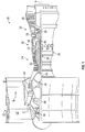
- FIG. 1 schematically illustrates a gas turbine engine 20.
- the gas turbine engine 20 is disclosed herein as a two-spool turbofan that generally incorporates a fan section 22, a compressor section 24, a combustor section 26 and a turbine section 28.
- Alternative engines might include other systems or features.
- the fan section 22 drives air along a bypass flow path B in a bypass duct, while the compressor section 24 drives air along a core flow path C for compression and communication into the combustor section 26 then expansion through the turbine section 28.
- FIG. 1 schematically illustrates a gas turbine engine 20.
- the gas turbine engine 20 is disclosed herein as a two-spool turbofan that generally incorporates a fan section 22, a compressor section 24, a combustor section 26 and a turbine section 28.
- Alternative engines might include other systems or features.
- the fan section 22 drives air along a bypass flow path B in a bypass duct
- the compressor section 24 drives air along a core flow path C for compression and communication into the combustor section 26
- the exemplary engine 20 generally includes a low speed spool 30 and a high speed spool 32 mounted for rotation about an engine central longitudinal axis A relative to an engine static structure 36 via several bearing systems 38. It should be understood that various bearing systems 38 at various locations may alternatively or additionally be provided, and the location of bearing systems 38 may be varied as appropriate to the application.
- the low speed spool 30 generally includes an inner shaft 40 that interconnects a fan 42, a low pressure compressor 44 and a low pressure turbine 46.
- the inner shaft 40 is connected to the fan 42 through a speed change mechanism, which in exemplary gas turbine engine 20 is illustrated as a geared architecture 48 to drive the fan 42 at a lower speed than the low speed spool 30.
- the high speed spool 32 includes an outer shaft 50 that interconnects a high pressure compressor 52 and high pressure turbine 54.
- a combustor 56 is arranged in exemplary gas turbine engine 20 between the high pressure compressor 52 and the high pressure turbine 54.
- An engine static structure 36 is arranged generally between the high pressure turbine 54 and the low pressure turbine 46.
- the engine static structure 36 further supports bearing systems 38 in the turbine section 28.
- the inner shaft 40 and the outer shaft 50 are concentric and rotate via bearing systems 38 about the engine central longitudinal axis A which is collinear with their longitudinal axes.
- each of the positions of the fan section 22, compressor section 24, combustor section 26, turbine section 28, and fan drive gear system 48 may be varied.
- gear system 48 may be located aft of combustor section 26 or even aft of turbine section 28, and fan section 22 may be positioned forward or aft of the location of gear system 48.
- the engine 20 in one example is a high-bypass geared aircraft engine.
- the engine 20 bypass ratio is greater than about six (6), with an example embodiment being greater than about ten (10)
- the geared architecture 48 is an epicyclic gear train, such as a planetary gear system or other gear system, with a gear reduction ratio of greater than about 2.3 and the low pressure turbine 46 has a pressure ratio that is greater than about five (5).
- the engine 20 bypass ratio is greater than about ten (10:1)
- the fan diameter is significantly larger than that of the low pressure compressor 44
- the low pressure turbine 46 has a pressure ratio that is greater than about five (5:1).
- Low pressure turbine 46 pressure ratio is pressure measured prior to inlet of low pressure turbine 46 as related to the pressure at the outlet of the low pressure turbine 46 prior to an exhaust nozzle.
- the geared architecture 48 may be an epicyclic gear train, such as a planetary gear system or other gear system, with a gear reduction ratio of greater than about 2.3:1. It should be understood, however, that the above parameters are only exemplary of one embodiment of a geared architecture engine and that the present disclosure is applicable to other gas turbine engines including direct drive turbofans.
- the fan section 22 of the engine 20 is designed for a particular flight condition--typically cruise at about 0.8 Mach and about 35,000 feet (10,668 meters).
- 'TSFC' Thrust Specific Fuel Consumption
- Low fan pressure ratio is the pressure ratio across the fan blade alone, without a Fan Exit Guide Vane (“FEGV”) system.
- the low fan pressure ratio as disclosed herein according to one non-limiting embodiment is less than about 1.45.
- Low corrected fan tip speed is the actual fan tip speed in ft/sec divided by an industry standard temperature correction of [(Tram °R)/(518.7 °R)] 0.5 .
- the "Low corrected fan tip speed” as disclosed herein according to one non-limiting embodiment is less than about 1150 ft/second (350.5 m/sec).
- FIG. 2 illustrated is a cross-sectional view of an exemplary high pressure compressor 52. While the following is described in the context of a high pressure compressor 52, one skilled in the art will readily appreciate that the present disclosure may be readily applied to other sections of the gas turbine engine 20, such as the low pressure compressor 44.
- the high pressure compressor 52 includes one or more rotors 60 and one or more stators 62 arranged in alternating rows or stages along the engine central longitudinal axis A.
- the stators include a plurality of stator vanes 64 secured to a fixed structure of the high pressure compressor 52, such as a compressor case 66.
- the stator vanes 64 are circumferentially fixed, relative to the engine central longitudinal axis A.
- Each rotor 60 rotates about the engine central longitudinal axis A, and includes a rotor hub 68 from which a plurality of circumferentially spaced rotor blades 70 extend radially outwardly.
- Each rotor blade 70 extends from a blade root 72 at the rotor hub 68 to a blade tip 74 defining a radially outboard extent of the rotor blade 70. Radial location of the blade tip 74 defines a tip clearance 76 between the rotor blade 70 and a rotationally fixed blade outer air seal 78 located at the compressor case 66. Further, each rotor blade 70 includes a blade leading edge 80 at an axially upstream end of the rotor blade 70 and a blade trailing edge 82 at an axially downstream end of the rotor blade 70, relative to the general direction of airflow through the high pressure compressor 52, parallel to engine central longitudinal axis A.
- a blade chord 84 is the distance between the blade leading edge 80 and the blade trailing edge 82
- a blade span 86 is the distance between the blade root 72 and the blade tip 74.
- the rotor blade 70 includes a pressure side 88 and a suction side 90.
- an air pressure at the pressure side 88 is greater than an air pressure at the suction side 90.
- a cross-sectional median line 92 is defined midway between the pressure side 88 and the suction side 90, and extends from the blade root 72 to the blade tip 74.
- the median line 92 extends in the radial direction 94 from the blade root 72 to a lean point 96 located at a selected position along the blade span 86.
- the median line 92 moves off of radial toward the pressure side 88, resulting in a lean of the rotor blade 70 between the lean point 96 and the blade tip 74.
- the lean point 96 is located between 80% blade span and 95% blade span, measured from the blade root 72.
- the lean point 96 is located at 90% blade span 86.
- the lean point 96 is located at a distance from the blade tip 74 equal to between 100% and 300% of the tip clearance 76 defined between the blade tip 74 and the outer air seal 78.
- the lean of the rotor blade 70 is further illustrated in FIG. 4 , which shows a rotor blade 70 profile at the lean point 96, indicated as "P1", with a rotor blade 70 profile at the blade tip 74, indicated as "P2".
- P2 is positioned offset from PI in a circumferential direction 100 indicating the direction of lean, having a lean magnitude 102.
- the lean magnitude 102 is related to the blade span 86, with in some embodiments the lean magnitude 102 being between 5% and 20% of the blade span 86.
- the lean magnitude 102 is related to the tip clearance 76 defined between the blade tip 74 and the outer air seal 78.
- the lean magnitude 102 being between 100% and 300% of the tip clearance 76.
- the median line 92 extends linearly from the lean point 96 to the blade tip 74, defining a linear lean of the blade tip 74. In other embodiments, the median line 92 extends in a curvilinear direction from the lean point 96 to the blade tip 74, defining a curvilinear lean of the blade tip 74.
- the blade tip lean introduces a local obstruction at the blade tip 74 to the flow of air into the tip clearance 76 and therefore reduce the blockage and loss associated with the tip clearance vortex.
- the reduced blockage and loss associated with the blade tip lean increases the efficiency of the rotor and reduces the loss coefficient across the following stator, therefore improving the efficiency of the compressor stage. Because the tangential momentum in the tip region is reduced, the angle that the clearance vortex makes with the rotor blade 70 is reduced, as is the angle between the rotor blade 70 and the interface between the clearance flow and the incoming flow. This delays stall by moving the point at which the clearance interface impacts the circumferentially adjacent rotor blade 70.
Landscapes
- Engineering & Computer Science (AREA)
- Mechanical Engineering (AREA)
- General Engineering & Computer Science (AREA)
- Physics & Mathematics (AREA)
- Fluid Mechanics (AREA)
- Architecture (AREA)
- Structures Of Non-Positive Displacement Pumps (AREA)
Abstract
Description
- Exemplary embodiments of the present disclosure pertain to the art of gas turbine engines, and in particular to rotor blades of a gas turbine engine.
- In gas turbine engine design, there is a trend toward smaller diameter core sections of the engine, in order to provide increased overall pressure ratio and increased bypass ratio without increasing overall engine diameter, including both the core and bypass flowpath. In an all-axial configuration, the high-pressure compressor of the small diameter core is limited in its performance by large tip clearance to rotor blade span ratio, and by large tip clearance to rotor blade chord ratios. These relative clearance sizes are larger than in larger diameter core compressors, due to the larger blade spans of such compressors. In the smaller diameter compressor, these larger ratios cause both reduced efficiency and reduced stall margin. To realize the cycle benefits of the increased overall pressure ratio, compressor efficiency cannot be compromised. There is, therefore, a need to increase efficiency at high tip clearance in small core axial configurations.
- In one embodiment, a rotor blade of a gas turbine engine includes a pressure side, and a suction side opposite the pressure side and defining a rotor blade profile therebetween, the pressure side and the suction side each extending from a blade root to a blade tip. The rotor blade defines a cross-sectional median line midway between the pressure side and the suction side. The cross-sectional median line extends in a generally radial direction from the blade root to a lean point between the blade root and the blade tip. The cross-sectional median line extends off of radial from the lean point to the blade tip, defining a lean of the rotor blade between the lean point and the blade tip.
- The lean point may be located or disposed at between 80% of a rotor blade radial span and 95% of the rotor blade radial span, measured from the blade root.
- The lean point may be located or disposed at 90% of the rotor blade radial span, measured from the blade root.
- The lean point may be located or disposed at a radial position defined relative to the blade tip by a distance equal to between 100% and 300% of the tip clearance, defined as the distance between the blade tip and an outer air seal.
- The cross-sectional median line may extend off of radial toward the pressure side from the lean point to the blade tip.
- The cross-sectional median line may extend off radial by a magnitude equal to between 5% and 20% of the rotor blade radial span.
- The cross-sectional median line may extend off radial by a magnitude equal to between 100% and 300% of the tip clearance, defined as the radial distance between the blade tip and an outer air seal.
- The cross-sectional median line may extend off radial in a linear direction.
- The cross-sectional median line may extend off radial in a curvilinear direction.
- In another embodiment, a rotor of a gas turbine engine includes a rotor hub and a plurality of rotor blades extending from the hub at a blade root outwardly to a blade tip. Each rotor blade includes a pressure side, and a suction side opposite the pressure side and defining a rotor blade profile therebetween. The pressure side and the suction side each extend from the blade root to the blade tip. The rotor blade defines a cross-sectional median line midway between the pressure side and the suction side. The cross-sectional median line extends in a general radial direction from the blade root to a lean point between the blade root and the blade tip. The cross-sectional median line extending off of radial from the lean point to the blade tip, defining a lean of the rotor blade between the lean point and the blade tip.
- The lean point may be located or disposed at between 80% of a rotor blade radial span and 95% of the rotor blade radial span, measured from the blade root.
- The lean point may be located or disposed at 90% of the rotor blade radial span, measured from the blade root.
- The lean point may be located or disposed at a radial position defined relative to the blade tip by a distance equal to between 100% and 300% of the tip clearance, defined as the distance between the blade tip and an outer air seal.
- The cross-sectional median line may extend off of radial toward the pressure side from the lean point to the blade tip.
- The cross-sectional median line may extend off radial by a magnitude equal to between 5% and 20% of the rotor blade radial span.
- The cross-sectional median line may extend off radial by a magnitude equal to between 100% and 300% of the tip clearance, defined as the radial distance between the blade tip and an outer air seal.
- The cross-sectional median line may extend off radial in a linear direction.
- The cross-sectional median line may extend off radial in a curvilinear direction.
- The rotor may be a high compressor rotor of the gas turbine engine.
- In yet another embodiment, a gas turbine engine includes a combustor and a compressor located upstream of the combustor to direct airflow to the combustor. The compressor including at least one rotor. The rotor includes a rotor hub and a plurality of rotor blades extending from the hub at a blade root outwardly to a blade tip. Each rotor blade includes a pressure side, and a suction side opposite the pressure side and defining a rotor blade profile therebetween. The pressure side and the suction side each extend from the blade root to the blade tip. The rotor blade defines a cross-sectional median line midway between the pressure side and the suction side. The cross-sectional median line extends radially from the blade root to a lean point between the blade root and the blade tip. The cross-sectional median line extends off of radial from the lean point to the blade tip, defining a lean of the rotor blade between the lean point and the blade tip.
- The following descriptions should not be considered limiting in any way. With reference to the accompanying drawings, which are given by way of example only, like elements are numbered alike:
-
FIG. 1 is a partial cross-sectional view of a gas turbine engine; -
FIG. 2 is a partial cross-sectional view of a high compressor section of a gas turbine engine; -
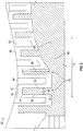
FIG. 3 is a cross-sectional view of an embodiment of a rotor blade of a rotor; and -
FIG. 4 is an overlay of cross-sectional profiles of a rotor blade of a gas turbine engine. - A detailed description of one or more embodiments of the disclosed apparatus and method are presented herein by way of exemplification and not limitation with reference to the Figures.
-
FIG. 1 schematically illustrates agas turbine engine 20. Thegas turbine engine 20 is disclosed herein as a two-spool turbofan that generally incorporates a fan section 22, acompressor section 24, acombustor section 26 and aturbine section 28. Alternative engines might include other systems or features. The fan section 22 drives air along a bypass flow path B in a bypass duct, while thecompressor section 24 drives air along a core flow path C for compression and communication into thecombustor section 26 then expansion through theturbine section 28. Although depicted as a two-spool turbofan gas turbine engine in the disclosed non-limiting embodiment, it should be understood that the concepts described herein are not limited to use with two-spool turbofans as the teachings may be applied to other types of turbine engines including three-spool architectures. - The
exemplary engine 20 generally includes alow speed spool 30 and ahigh speed spool 32 mounted for rotation about an engine central longitudinal axis A relative to an enginestatic structure 36 viaseveral bearing systems 38. It should be understood thatvarious bearing systems 38 at various locations may alternatively or additionally be provided, and the location ofbearing systems 38 may be varied as appropriate to the application. - The
low speed spool 30 generally includes aninner shaft 40 that interconnects afan 42, alow pressure compressor 44 and alow pressure turbine 46. Theinner shaft 40 is connected to thefan 42 through a speed change mechanism, which in exemplarygas turbine engine 20 is illustrated as a gearedarchitecture 48 to drive thefan 42 at a lower speed than thelow speed spool 30. Thehigh speed spool 32 includes anouter shaft 50 that interconnects ahigh pressure compressor 52 andhigh pressure turbine 54. Acombustor 56 is arranged in exemplarygas turbine engine 20 between thehigh pressure compressor 52 and thehigh pressure turbine 54. An enginestatic structure 36 is arranged generally between thehigh pressure turbine 54 and thelow pressure turbine 46. The enginestatic structure 36 furthersupports bearing systems 38 in theturbine section 28. Theinner shaft 40 and theouter shaft 50 are concentric and rotate via bearingsystems 38 about the engine central longitudinal axis A which is collinear with their longitudinal axes. - The core airflow is compressed by the
low pressure compressor 44 then thehigh pressure compressor 52, mixed and burned with fuel in thecombustor 56, then expanded over thehigh pressure turbine 54 andlow pressure turbine 46. Theturbines low speed spool 30 andhigh speed spool 32 in response to the expansion. It will be appreciated that each of the positions of the fan section 22,compressor section 24,combustor section 26,turbine section 28, and fandrive gear system 48 may be varied. For example,gear system 48 may be located aft ofcombustor section 26 or even aft ofturbine section 28, and fan section 22 may be positioned forward or aft of the location ofgear system 48. - The
engine 20 in one example is a high-bypass geared aircraft engine. In a further example, theengine 20 bypass ratio is greater than about six (6), with an example embodiment being greater than about ten (10), the gearedarchitecture 48 is an epicyclic gear train, such as a planetary gear system or other gear system, with a gear reduction ratio of greater than about 2.3 and thelow pressure turbine 46 has a pressure ratio that is greater than about five (5). In one disclosed embodiment, theengine 20 bypass ratio is greater than about ten (10:1), the fan diameter is significantly larger than that of thelow pressure compressor 44, and thelow pressure turbine 46 has a pressure ratio that is greater than about five (5:1).Low pressure turbine 46 pressure ratio is pressure measured prior to inlet oflow pressure turbine 46 as related to the pressure at the outlet of thelow pressure turbine 46 prior to an exhaust nozzle. The gearedarchitecture 48 may be an epicyclic gear train, such as a planetary gear system or other gear system, with a gear reduction ratio of greater than about 2.3:1. It should be understood, however, that the above parameters are only exemplary of one embodiment of a geared architecture engine and that the present disclosure is applicable to other gas turbine engines including direct drive turbofans. - A significant amount of thrust is provided by the bypass flow B due to the high bypass ratio. The fan section 22 of the
engine 20 is designed for a particular flight condition--typically cruise at about 0.8 Mach and about 35,000 feet (10,668 meters). The flight condition of 0.8 Mach and 35,000 ft (10,668 meters), with the engine at its best fuel consumption--also known as "bucket cruise Thrust Specific Fuel Consumption ('TSFC')"--is the industry standard parameter of lbm of fuel being burned divided by lbf of thrust the engine produces at that minimum point. "Low fan pressure ratio" is the pressure ratio across the fan blade alone, without a Fan Exit Guide Vane ("FEGV") system. The low fan pressure ratio as disclosed herein according to one non-limiting embodiment is less than about 1.45. "Low corrected fan tip speed" is the actual fan tip speed in ft/sec divided by an industry standard temperature correction of [(Tram °R)/(518.7 °R)]0.5. The "Low corrected fan tip speed" as disclosed herein according to one non-limiting embodiment is less than about 1150 ft/second (350.5 m/sec). - Referring now to
FIG. 2 , illustrated is a cross-sectional view of an exemplaryhigh pressure compressor 52. While the following is described in the context of ahigh pressure compressor 52, one skilled in the art will readily appreciate that the present disclosure may be readily applied to other sections of thegas turbine engine 20, such as thelow pressure compressor 44. - The
high pressure compressor 52 includes one ormore rotors 60 and one ormore stators 62 arranged in alternating rows or stages along the engine central longitudinal axis A. The stators include a plurality ofstator vanes 64 secured to a fixed structure of thehigh pressure compressor 52, such as acompressor case 66. The stator vanes 64 are circumferentially fixed, relative to the engine central longitudinal axis A. Eachrotor 60 rotates about the engine central longitudinal axis A, and includes arotor hub 68 from which a plurality of circumferentially spacedrotor blades 70 extend radially outwardly. Eachrotor blade 70 extends from ablade root 72 at therotor hub 68 to ablade tip 74 defining a radially outboard extent of therotor blade 70. Radial location of theblade tip 74 defines atip clearance 76 between therotor blade 70 and a rotationally fixed bladeouter air seal 78 located at thecompressor case 66. Further, eachrotor blade 70 includes ablade leading edge 80 at an axially upstream end of therotor blade 70 and ablade trailing edge 82 at an axially downstream end of therotor blade 70, relative to the general direction of airflow through thehigh pressure compressor 52, parallel to engine central longitudinal axis A. Ablade chord 84 is the distance between theblade leading edge 80 and theblade trailing edge 82, and ablade span 86 is the distance between theblade root 72 and theblade tip 74. - Referring now to
FIG. 3 , therotor blade 70 includes apressure side 88 and asuction side 90. During operation of thegas turbine engine 20, an air pressure at thepressure side 88 is greater than an air pressure at thesuction side 90. In the cross-sectional view ofFIG. 3 , a cross-sectionalmedian line 92 is defined midway between thepressure side 88 and thesuction side 90, and extends from theblade root 72 to theblade tip 74. Themedian line 92 extends in theradial direction 94 from theblade root 72 to alean point 96 located at a selected position along theblade span 86. From thelean point 96 to theblade tip 74, themedian line 92 moves off of radial toward thepressure side 88, resulting in a lean of therotor blade 70 between thelean point 96 and theblade tip 74. In some embodiments, thelean point 96 is located between 80% blade span and 95% blade span, measured from theblade root 72. In another embodiment, thelean point 96 is located at 90% blade span 86. In another embodiment, thelean point 96 is located at a distance from theblade tip 74 equal to between 100% and 300% of thetip clearance 76 defined between theblade tip 74 and theouter air seal 78. - The lean of the
rotor blade 70 is further illustrated inFIG. 4 , which shows arotor blade 70 profile at thelean point 96, indicated as "P1", with arotor blade 70 profile at theblade tip 74, indicated as "P2". P2 is positioned offset from PI in acircumferential direction 100 indicating the direction of lean, having alean magnitude 102. In some embodiments, thelean magnitude 102 is related to theblade span 86, with in some embodiments thelean magnitude 102 being between 5% and 20% of theblade span 86. In another embodiment thelean magnitude 102 is related to thetip clearance 76 defined between theblade tip 74 and theouter air seal 78. In some embodiments thelean magnitude 102 being between 100% and 300% of thetip clearance 76. In some embodiments, themedian line 92 extends linearly from thelean point 96 to theblade tip 74, defining a linear lean of theblade tip 74. In other embodiments, themedian line 92 extends in a curvilinear direction from thelean point 96 to theblade tip 74, defining a curvilinear lean of theblade tip 74. - The blade tip lean introduces a local obstruction at the
blade tip 74 to the flow of air into thetip clearance 76 and therefore reduce the blockage and loss associated with the tip clearance vortex. The reduced blockage and loss associated with the blade tip lean increases the efficiency of the rotor and reduces the loss coefficient across the following stator, therefore improving the efficiency of the compressor stage. Because the tangential momentum in the tip region is reduced, the angle that the clearance vortex makes with therotor blade 70 is reduced, as is the angle between therotor blade 70 and the interface between the clearance flow and the incoming flow. This delays stall by moving the point at which the clearance interface impacts the circumferentiallyadjacent rotor blade 70. - The term "about" is intended to include the degree of error associated with measurement of the particular quantity based upon the equipment available at the time of filing the application. For example, "about" can include a range of ± 8% or 5%, or 2% of a given value.
- The terminology used herein is for the purpose of describing particular embodiments only and is not intended to be limiting of the present disclosure. As used herein, the singular forms "a", "an" and "the" are intended to include the plural forms as well, unless the context clearly indicates otherwise. It will be further understood that the terms "comprises" and/or "comprising," when used in this specification, specify the presence of stated features, integers, steps, operations, elements, and/or components, but do not preclude the presence or addition of one or more other features, integers, steps, operations, element components, and/or groups thereof.
- While the present disclosure has been described with reference to an exemplary embodiment or embodiments, it will be understood by those skilled in the art that various changes may be made and equivalents may be substituted for elements thereof without departing from the scope of the present disclosure. In addition, many modifications may be made to adapt a particular situation or material to the teachings of the present disclosure without departing from the essential scope thereof as defined in the claims. Therefore, it is intended that the present disclosure not be limited to the particular embodiment disclosed as the best mode contemplated for carrying out this present disclosure, but that the present disclosure will include all embodiments falling within the scope of the claims.
Claims (12)
- A rotor blade (70) of a gas turbine engine (20), comprising:a pressure side (88); anda suction side (90) opposite the pressure side and defining a rotor blade profile therebetween, the pressure side and the suction side each extending from a blade root (72) to a blade tip (74);wherein the rotor blade defines a cross-sectional median line (92) midway between the pressure side and the suction side, the cross-sectional median line extending in a generally radial direction from the blade root to a lean point (96) between the blade root and the blade tip, the cross-sectional median line extending off of radial from the lean point to the blade tip, defining a lean of the rotor blade between the lean point and the blade tip.
- The rotor blade of claim 1, wherein the lean point is disposed at between 80% of a rotor blade radial span (86) and 95% of the rotor blade radial span, measured from the blade root.
- The rotor blade of claim 2, wherein the lean point is disposed at 90% of the rotor blade radial span, measured from the blade root.
- The rotor blade of claim 1, 2 or 3, wherein the lean point is disposed at a radial position defined relative to the blade tip by a distance equal to between 100% and 300% of the tip clearance (76), defined as the distance between the blade tip and the outer air seal (78).
- The rotor blade of any of claims 1 to 3, wherein the cross-sectional median line extends off of radial toward the pressure side from the lean point to the blade tip.
- The rotor blade of any preceding claim, wherein the cross-sectional median line extends off radial by a magnitude (102) equal to between 5% and 20% of the rotor blade radial span.
- The rotor blade of any preceding claim, wherein the cross-sectional median line extends off radial by a magnitude equal to between 100% and 300% of the tip clearance, defined as the radial distance between the blade tip and the outer air seal.
- The rotor blade of any preceding claim, wherein the cross-sectional median line extends off radial in a linear direction.
- The rotor blade of any of claims 1 to 7, wherein the cross-sectional median line extends off radial in a curvilinear direction.
- A rotor (60) of a gas turbine engine (20), comprising:a rotor hub (68); anda plurality of rotor blades (70) extending from the hub at a blade root (72) outwardly to a blade tip (74), each rotor blade as claimed in any preceding claim.
- The rotor of claim 10, wherein the rotor is a high compressor rotor of the gas turbine engine.
- A gas turbine engine (20), comprising:a combustor (56); anda compressor (44, 52) disposed upstream of the combustor to direct airflow to the combustor, the compressor including at least one rotor as claimed in claim 10 or 11.
Applications Claiming Priority (1)
| Application Number | Priority Date | Filing Date | Title |
|---|---|---|---|
| US16/225,995 US10947851B2 (en) | 2018-12-19 | 2018-12-19 | Local pressure side blade tip lean |
Publications (1)
| Publication Number | Publication Date |
|---|---|
| EP3670835A1 true EP3670835A1 (en) | 2020-06-24 |
Family
ID=68848154
Family Applications (1)
| Application Number | Title | Priority Date | Filing Date |
|---|---|---|---|
| EP19215014.2A Pending EP3670835A1 (en) | 2018-12-19 | 2019-12-10 | Gas turbine engine rotor blade with a local pressure side blade tip lean |
Country Status (2)
| Country | Link |
|---|---|
| US (1) | US10947851B2 (en) |
| EP (1) | EP3670835A1 (en) |
Families Citing this family (2)
| Publication number | Priority date | Publication date | Assignee | Title |
|---|---|---|---|---|
| US11913353B2 (en) | 2021-08-06 | 2024-02-27 | Rtx Corporation | Airfoil tip arrangement for gas turbine engine |
| US12509988B2 (en) | 2024-06-14 | 2025-12-30 | Pratt & Whitney Canada Corp. | Turbine engine airfoil |
Citations (7)
| Publication number | Priority date | Publication date | Assignee | Title |
|---|---|---|---|---|
| DE560589C (en) * | 1932-10-04 | Franz Burghauser Dipl Ing | Device for reducing the blade gap loss of steam and gas turbines | |
| US2714499A (en) * | 1952-10-02 | 1955-08-02 | Gen Electric | Blading for turbomachines |
| GB1231424A (en) * | 1968-11-15 | 1971-05-12 | ||
| WO2014109959A1 (en) * | 2013-01-08 | 2014-07-17 | United Technologies Corporation | Gas turbine engine rotor blade |
| US20140234112A1 (en) * | 2012-11-16 | 2014-08-21 | Rolls-Royce Plc | Rotor blade |
| EP2820279A2 (en) * | 2012-02-29 | 2015-01-07 | United Technologies Corporation | High order shaped curve region for an airfoil |
| US20180298912A1 (en) * | 2017-04-18 | 2018-10-18 | Rolls-Royce Plc | Compressor blades and/or vanes |
Family Cites Families (9)
| Publication number | Priority date | Publication date | Assignee | Title |
|---|---|---|---|---|
| US1828409A (en) * | 1929-01-11 | 1931-10-20 | Westinghouse Electric & Mfg Co | Reaction blading |
| US5525038A (en) * | 1994-11-04 | 1996-06-11 | United Technologies Corporation | Rotor airfoils to control tip leakage flows |
| DE102004011607B4 (en) | 2004-03-10 | 2016-11-24 | MTU Aero Engines AG | Compressor of a gas turbine and gas turbine |
| ATE553284T1 (en) | 2007-02-05 | 2012-04-15 | Siemens Ag | TURBINE BLADE |
| US20150164706A1 (en) | 2012-07-12 | 2015-06-18 | Chaim Ben Natan | Anti-irritant disposable diaper |
| US9856739B2 (en) * | 2013-09-18 | 2018-01-02 | Honeywell International Inc. | Turbine blades with tip portions having converging cooling holes |
| US10233758B2 (en) | 2013-10-08 | 2019-03-19 | United Technologies Corporation | Detuning trailing edge compound lean contour |
| FR3040071B1 (en) * | 2015-08-11 | 2020-03-27 | Safran Aircraft Engines | TURBOMACHINE ROTOR DAWN |
| FR3043715B1 (en) * | 2015-11-16 | 2020-11-06 | Snecma | TURBINE VANE INCLUDING A BLADE WITH A TUB WITH A CURVED INTRADOS IN THE PALE TOP REGION |
-
2018
- 2018-12-19 US US16/225,995 patent/US10947851B2/en active Active
-
2019
- 2019-12-10 EP EP19215014.2A patent/EP3670835A1/en active Pending
Patent Citations (7)
| Publication number | Priority date | Publication date | Assignee | Title |
|---|---|---|---|---|
| DE560589C (en) * | 1932-10-04 | Franz Burghauser Dipl Ing | Device for reducing the blade gap loss of steam and gas turbines | |
| US2714499A (en) * | 1952-10-02 | 1955-08-02 | Gen Electric | Blading for turbomachines |
| GB1231424A (en) * | 1968-11-15 | 1971-05-12 | ||
| EP2820279A2 (en) * | 2012-02-29 | 2015-01-07 | United Technologies Corporation | High order shaped curve region for an airfoil |
| US20140234112A1 (en) * | 2012-11-16 | 2014-08-21 | Rolls-Royce Plc | Rotor blade |
| WO2014109959A1 (en) * | 2013-01-08 | 2014-07-17 | United Technologies Corporation | Gas turbine engine rotor blade |
| US20180298912A1 (en) * | 2017-04-18 | 2018-10-18 | Rolls-Royce Plc | Compressor blades and/or vanes |
Also Published As
| Publication number | Publication date |
|---|---|
| US10947851B2 (en) | 2021-03-16 |
| US20200200014A1 (en) | 2020-06-25 |
Similar Documents
| Publication | Publication Date | Title |
|---|---|---|
| US11078805B2 (en) | Inclination of forward and aft groove walls of casing treatment for gas turbine engine | |
| US10808621B2 (en) | Gas turbine engine having support structure with swept leading edge | |
| EP3112591B1 (en) | Tip shrouded high aspect ratio compressor stage | |
| US11047397B2 (en) | Gas turbine engine stator vane mistuning | |
| EP3108123A2 (en) | Gas turbine engine airfoil | |
| EP3108116A2 (en) | Gas turbine engine airfoil | |
| US20140212297A1 (en) | Gas turbine engine serpentine cooling passage with chevrons | |
| EP3061910A1 (en) | Gas turbine engine airfoil and corresponding method of forming | |
| EP3428390A1 (en) | Compressor rotor stack assembly for gas turbine engine | |
| WO2014042955A1 (en) | Gas turbine engine serpentine cooling passage | |
| WO2013154650A2 (en) | Anti-icing core inlet stator assembly for a gas turbine engine | |
| EP3670835A1 (en) | Gas turbine engine rotor blade with a local pressure side blade tip lean | |
| EP3108102A1 (en) | Gas turbine engine airfoil | |
| EP3008291B1 (en) | Turbine vane with non-uniform wall thickness | |
| EP3045663B1 (en) | Integrally bladed fan rotor with pressure side thickness on blade traing edge | |
| EP3108120B1 (en) | Gas turbine engine having a geared architecture and a specific fixed airfoil structure | |
| US20240159247A1 (en) | Casing Treatment for Gas Turbine Engines | |
| EP3453837B1 (en) | Fan exit stator assembly retention system | |
| EP3693544A1 (en) | Gas turbine tangential on board injector with a full sweeping nozzle | |
| US20260092568A1 (en) | Compressor bleed port with cavity intake wire | |
| US11203944B2 (en) | Flared fan hub slot | |
| EP3290717A1 (en) | Compressor blade with specific spanwise pressure and velocity profile |
Legal Events
| Date | Code | Title | Description |
|---|---|---|---|
| PUAI | Public reference made under article 153(3) epc to a published international application that has entered the european phase |
Free format text: ORIGINAL CODE: 0009012 |
|
| STAA | Information on the status of an ep patent application or granted ep patent |
Free format text: STATUS: THE APPLICATION HAS BEEN PUBLISHED |
|
| AK | Designated contracting states |
Kind code of ref document: A1 Designated state(s): AL AT BE BG CH CY CZ DE DK EE ES FI FR GB GR HR HU IE IS IT LI LT LU LV MC MK MT NL NO PL PT RO RS SE SI SK SM TR |
|
| AX | Request for extension of the european patent |
Extension state: BA ME |
|
| STAA | Information on the status of an ep patent application or granted ep patent |
Free format text: STATUS: REQUEST FOR EXAMINATION WAS MADE |
|
| 17P | Request for examination filed |
Effective date: 20201223 |
|
| RBV | Designated contracting states (corrected) |
Designated state(s): AL AT BE BG CH CY CZ DE DK EE ES FI FR GB GR HR HU IE IS IT LI LT LU LV MC MK MT NL NO PL PT RO RS SE SI SK SM TR |
|
| RAP1 | Party data changed (applicant data changed or rights of an application transferred) |
Owner name: RAYTHEON TECHNOLOGIES CORPORATION |
|
| STAA | Information on the status of an ep patent application or granted ep patent |
Free format text: STATUS: EXAMINATION IS IN PROGRESS |
|
| 17Q | First examination report despatched |
Effective date: 20220207 |
|
| RAP3 | Party data changed (applicant data changed or rights of an application transferred) |
Owner name: RTX CORPORATION |