EP3670811A1 - Glass removal sensor for detecting removal of a pane from a window or door - Google Patents
Glass removal sensor for detecting removal of a pane from a window or door Download PDFInfo
- Publication number
- EP3670811A1 EP3670811A1 EP19218762.3A EP19218762A EP3670811A1 EP 3670811 A1 EP3670811 A1 EP 3670811A1 EP 19218762 A EP19218762 A EP 19218762A EP 3670811 A1 EP3670811 A1 EP 3670811A1
- Authority
- EP
- European Patent Office
- Prior art keywords
- glass
- sensor
- conductive
- glass unit
- wire
- Prior art date
- Legal status (The legal status is an assumption and is not a legal conclusion. Google has not performed a legal analysis and makes no representation as to the accuracy of the status listed.)
- Granted
Links
- 239000011521 glass Substances 0.000 title claims abstract description 321
- 239000011888 foil Substances 0.000 claims description 32
- 229910052751 metal Inorganic materials 0.000 claims description 20
- 239000002184 metal Substances 0.000 claims description 20
- RYGMFSIKBFXOCR-UHFFFAOYSA-N Copper Chemical compound [Cu] RYGMFSIKBFXOCR-UHFFFAOYSA-N 0.000 claims description 7
- 229910000831 Steel Inorganic materials 0.000 claims description 7
- 229910052782 aluminium Inorganic materials 0.000 claims description 7
- XAGFODPZIPBFFR-UHFFFAOYSA-N aluminium Chemical compound [Al] XAGFODPZIPBFFR-UHFFFAOYSA-N 0.000 claims description 7
- PCHJSUWPFVWCPO-UHFFFAOYSA-N gold Chemical compound [Au] PCHJSUWPFVWCPO-UHFFFAOYSA-N 0.000 claims description 7
- 239000010959 steel Substances 0.000 claims description 7
- 239000011889 copper foil Substances 0.000 claims description 5
- 239000003973 paint Substances 0.000 description 9
- 239000006260 foam Substances 0.000 description 8
- 238000009413 insulation Methods 0.000 description 6
- 239000000853 adhesive Substances 0.000 description 4
- 230000001070 adhesive effect Effects 0.000 description 4
- 230000004888 barrier function Effects 0.000 description 4
- 239000004020 conductor Substances 0.000 description 3
- 238000000034 method Methods 0.000 description 3
- 229910001369 Brass Inorganic materials 0.000 description 2
- 239000010951 brass Substances 0.000 description 2
- 238000004891 communication Methods 0.000 description 2
- 229910052802 copper Inorganic materials 0.000 description 2
- 239000010949 copper Substances 0.000 description 2
- 230000005684 electric field Effects 0.000 description 2
- 239000003292 glue Substances 0.000 description 2
- 239000010931 gold Substances 0.000 description 2
- 229910052737 gold Inorganic materials 0.000 description 2
- 238000002955 isolation Methods 0.000 description 2
- 239000000463 material Substances 0.000 description 2
- 125000006850 spacer group Chemical group 0.000 description 2
- 235000014676 Phragmites communis Nutrition 0.000 description 1
- 239000002313 adhesive film Substances 0.000 description 1
- 239000003990 capacitor Substances 0.000 description 1
- 238000005266 casting Methods 0.000 description 1
- 239000011248 coating agent Substances 0.000 description 1
- 238000000576 coating method Methods 0.000 description 1
- 230000005611 electricity Effects 0.000 description 1
- 239000002320 enamel (paints) Substances 0.000 description 1
- 238000005516 engineering process Methods 0.000 description 1
- 239000005357 flat glass Substances 0.000 description 1
- 238000007373 indentation Methods 0.000 description 1
- 239000011810 insulating material Substances 0.000 description 1
- 239000012774 insulation material Substances 0.000 description 1
- 239000012212 insulator Substances 0.000 description 1
- 238000001556 precipitation Methods 0.000 description 1
- 230000001902 propagating effect Effects 0.000 description 1
- 239000000523 sample Substances 0.000 description 1
- 238000000926 separation method Methods 0.000 description 1
- 230000035939 shock Effects 0.000 description 1
Images


Classifications
-
- G—PHYSICS
- G08—SIGNALLING
- G08B—SIGNALLING OR CALLING SYSTEMS; ORDER TELEGRAPHS; ALARM SYSTEMS
- G08B13/00—Burglar, theft or intruder alarms
- G08B13/02—Mechanical actuation
- G08B13/08—Mechanical actuation by opening, e.g. of door, of window, of drawer, of shutter, of curtain, of blind
-
- E—FIXED CONSTRUCTIONS
- E06—DOORS, WINDOWS, SHUTTERS, OR ROLLER BLINDS IN GENERAL; LADDERS
- E06B—FIXED OR MOVABLE CLOSURES FOR OPENINGS IN BUILDINGS, VEHICLES, FENCES OR LIKE ENCLOSURES IN GENERAL, e.g. DOORS, WINDOWS, BLINDS, GATES
- E06B5/00—Doors, windows, or like closures for special purposes; Border constructions therefor
- E06B5/10—Doors, windows, or like closures for special purposes; Border constructions therefor for protection against air-raid or other war-like action; for other protective purposes
- E06B5/11—Doors, windows, or like closures for special purposes; Border constructions therefor for protection against air-raid or other war-like action; for other protective purposes against burglary
Definitions
- the present disclosure relates to a glass removal sensor for detecting removal of a glass pane, such as a framed glass pane, in a window or a door.
- the sensor may be configured for sensing removal of the glass pane without breaking the glass.
- a burglar breaking in to a building may gain access to the building in various ways.
- the windows of a building are naturally a vulnerable area and needs to be protected by an alarm system such that a beak-in is detected.
- Alarm systems today may detect if a window is open or closed and give off an alarm if the window is opened when it should be closed. This may be achieved by a sensor at the window.
- An alarm system may further be configured for detecting breaking or shattering of a window in the building. Such detectors work either by sensing the shock or vibrations from breaking glass or by detecting specific frequencies characterizing the sound of breaking glass using a microphone.
- While such sensors do provide good capabilities of detecting a break-in, they do not cover all possible methods used by burglars.
- One method not covered by such systems is the removal of the entire window glass, either the glass pane or the glass pane with its frame, without breaking it.
- the glass pane optionally the glass pane and its frame, may be pry opened and removed from the sash of the window. Since the window remains closed, the alarm is not set off.
- Conventional glass break detectors and magnetic sensor for detecting if a window is opened will not detect this type of break-in.
- This is provided by the present disclosure relating to a glass removal sensor for detecting removal of a glass unit in a window or a door.
- the glass removal sensor for detecting removal of a glass unit having a glass pane and optionally a glass frame, in a window comprises:
- the sensor assembly preferably a sensor assembly having a thin shape, with an additional capacitive sensor arrangement, can be used to detect the removal of the glass unit from the sash.
- the sensor assembly may thereby be configured to detect a change of state of the capacitive sensor in response to an externally generated change in capacitance between the first conductive area and a reference point of the sensor assembly.
- the capacitive sensor can be implemented in different embodiments.
- the sensor may be configured to sense an externally generated change in capacitance value between the first conductive area and a second conductive area. This may be achieved in several configurations, as will be demonstrated in the present disclosure.
- the definitions of the terms 'glass unit' i.e.
- 'sash' i.e. the glass unit and an additional frame, usually the frame of the movable part of a window, or equivalently the outer portion of a door
- 'jamb' head jamb/side jamb/
- 'sill' may be useful for the interpretation of the claimed physical arrangements and functioning of the present glass removal sensor and window.
- the sensor assembly may be a thin, such as thinner than 5 mm, and elongated, assembly.
- the sensor assembly can be mounted for example on or in the sash of the window or on a door holding a glass pane, i.e. for example on the outside of the movable part of a window, or in the movable part of the door assembly.
- the sensor assembly can be mounted on the sash using an adhesive film.
- the first conductive area and/or a second conductive area of the sensor assembly can then be connected, directly or indirectly, to the glass unit, which is a part of the window or door that sometimes can be replaced and sometimes also removed by introducers to break into a building.
- One advantage of the presently disclosed glass removal sensor is that the glass unit still can be replaced relatively easily. Only the wire or conductive element that is attached to the glass unit needs to be re-attached.
- the first conductive element is arranged between the sensor assembly and the glass unit.
- the first conductive element may comprise a first wire having first and second wire-end conductive areas.
- the first wire-end conductive area may be arranged adjacent to the corresponding first conductive area of the sensor assembly.
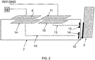
- the second wire-end conductive area may be located in the other end of the conductive element towards the glass unit, as shown in fig. 2 , adjacent to a second conductive element in the form of for example a piece of foil.
- the second wire may comprise a third wire-end conductive area towards a corresponding second conductive area of the sensor assembly, which may be connected to a ground plane or other reference level.
- the wire may further comprise a fourth wire-end conductive area in the other end towards the glass unit adjacent to a second conductive element in the form of for example a piece of foil.
- Fig. 2 shows such an embodiment.
- the wires may extend for example through a hole in the sash.
- a glass unit conductive element may be arranged to make a resistive or capacitive short-circuit between the two parallel wires. Removing the entire glass unit from the correctly mounted position will break the short-circuit, thereby also changing the capacitive value at the capacitive sensor.
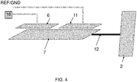
- the first conductive element is arranged between the sensor assembly (which is mounted on the sash) and the glass unit.
- the conductive element makes a resistive or capacitive short circuit between the capacitive sensor and the ground plane or the second conductive area. If the conductive element is removed or broken the short circuit between the capacitive sensor and ground is removed, which causes a change in capacitance measured by the capacitive sensor. If the conductive element is mounted on the glass unit, for example by means of a mechanical wire, in such a way that it is pulled away from the capacitive sensor or such that the connectivity is broken when the glass unit is removed from its correct position, it will break the short-circuit, thereby also changing the capacitive value at the capacitive sensor. This embodiment is shown in fig. 4 .
- the present disclosure further relates to a window and to a door, said window or door comprising;
- the glass removal sensor may be referred to as a window sensor assembly or a door sensor assembly.
- the glass removal sensor is suitable both for windows that can be opened and windows of the type that cannot be opened, which have a replaceable glass unit, optionally in a frame.
- a capacitive sensor in capacitive sensing generally refers to any material capable of propagating an external change of capacitance.
- a capacitive sensor may be arranged such that an external object approaching it will increase the capacitance between a sensor node or conductive area and a reference point, such as a ground node or a secondary node/area.
- the term 'capacitive connection' is used for a connection between two or more conductive elements separated by an insulator, where the capacitance between the elements is changed due to changes of the insulation layer such as changed size or insulation material characteristics. A change in distance between the elements may also change the capacitance between the elements.
- a 'glass unit' is referred to as a sheet of glass (glass pane), which optionally has a frame holding the glass pane.
- a glass unit may also be a framed or unframed double-pane or triple-pane glass unit.
- An example of a 'glass unit' can be found in fig. 9 .
- the glass pane 3 and its frame 4 constitute the glass unit, which may be replaced.
- a 'sash' of a window is the frame of the part of the window that opens and closes.
- An example is shown in fig. 9 , where the 'sash' (8) holds the 'glass unit' (4 and 3)
- the type of burglary that is prevented by the presently disclosed window sensor is the separation of the 'glass unit' from the 'sash'.
- the 'sash' is typically the part of the movable part of the window that has a handle (28).
- a door may be constructed equivalently to a window in the sense that it has an outer portion (corresponding to the 'sash' of a window) holding a glass unit.
- a window typically further comprises a fixed frame or framework firmly attached to a wall in a fixed position.
- the fixed frame has a 'head jamb' 26, two 'side jambs' 25 and a 'sill' 27.
- the presently disclosed glass removal sensor can be used both for windows and doors having a glass unit. Where the description refers to a window specifically, the skilled person will also acknowledge that the technology can be applied to a door.
- the present disclosure relates to a glass removal sensor for detecting removal of a glass unit from the sash of a window or a corresponding door frame.
- the glass removal sensor comprises a sensor assembly having a capacitive sensor and at least a first conductive element connected, directly or indirectly, between the first conductive area of the sensor assembly and the glass unit such that removal of the glass unit from the sash causes a change of capacitance that can be measured by the capacitive sensor.
- the sensor assembly comprises a capacitive sensor and at least a first conductive area in connection with the capacitive sensor.
- Capacitance describes how the space between two conductors affects an electric field between them. If two conductive plates are placed close to each other and a voltage is applied, an electric field will be generated between the plates. In a capacitive sensor, a surface of the probe corresponds to one of the plates, whereas an external plate or object corresponds to the second plate. When the distance between the two plates is changed, a capacitance change will occur. When this change exceeds a predetermined value, the capacitive sensor generates a signal.
- the glass removal sensor further comprises at least a first wire attached, directly or indirectly, between the first conductive element and the glass unit of the window/door such that when the glass unit is removed from a sash of the window it causes a change of capacitance detected by the capacitive sensor.
- the first conductive wire and a parallel second conductive wire having wire-end conductive areas in both end are arranged between the sensor assembly and a second conductive element attached to the glass unit, and another embodiment in which the wire is used to pull the first conductive element away from a position adjacent to the sensor assembly when the glass unit is removed from the sash.
- the sensor assembly is a very thin assembly, such as having a maximum height of less than 5 mm, which is mounted on a surface of the sash. The thin design of the sensor assembly may allow the sensor assembly to be positioned between the sash and the fixed frame of the window when the window is closed.
- the sensor assembly can be placed in a groove of the sash or even inside the sash. If the sash is hollow and possibly filled with an insulating material, a cavity can be formed in the sash by removing the insulation so that the sensor assembly can be positioned inside the sash. In any of the above placements, the sensor assembly can be hidden from potential intruders and may not be easily removed. In addition, the sensor assembly is protected from environmental exposure like sunshine and precipitation.
- the first conductive element may be capacitively connected to the first and second conductive area of the sensor assembly.
- the first conductive element may comprise two conducting wires with a conductive area in each of the four ends.
- the first conductive element may be a single conductive area that capacitively short circuits the first and the second capacitive area in the sensor assembly.
- the first conductive element may be a first piece of foil, such as a metal foil, such as aluminum foil, or copper foil, or steel foil, or gold foil or metal tape, exemplified in fig. 3 and 4 .
- the first conductive element may be arranged to cover the first conductive area and the second conductive area of the sensor assembly at least partly when the sensor assembly is placed in its position against the sash.
- the first conductive element may be adapted to be mounted between the sensor assembly and the sash.
- the first conductive element is not attached to the sensor assembly, but may be attachable to the sash. In case the sensor assembly is positioned in a groove of the sash, the first conductive element may accordingly be positioned in the same groove.
- the first conductive element will typically be further connected to an arrangement at or adjacent to the glass unit, which will create the change of capacitance.
- the glass removal sensor may therefore further comprise a second conductive element attachable to the glass unit.
- An example of such a second conductive element (10) is shown in fig. 2 in the form of a metal foil.
- the second conductive element may be a piece of foil, such as a metal foil, such as aluminum foil, or copper foil, or steel foil, or gold foil or metal tape.
- the first and second conductive areas may be connected using the first wire and a parallel second wire and a second conductive element connecting the first and second wires.
- the first wire may by any wire and not necessarily a conducting wire.
- the first wire may be attached to the glass unit, optionally attached to an attachment element which is attached to the glass unit, and configured such that when the glass unit is removed from the sash, the first wire pulls the first conductive element away from the first conductive area.
- the first conductive element may be pulled through a hole in the sash.
- the capacitive sensor will detect a change in the measured capacitive value as a consequence of the first conductive element being removed from the conductive area.
- the sensor assembly which preferably is an elongated and thin sensor assembly, may further comprise:
- the microprocessor may be any kind of processing unit implemented in a circuit configured to: detect one or more changes of state of the capacitive sensor and optionally other sensors.
- the maximum height/thickness of the sensor assembly should be kept to a minimum, i.e. preferably less than 5 mm, more preferably less than 4.5 mm, yet more preferably less than 4 mm, or less than 3.5 mm, even more preferably less than 3 mm, yet more preferably less than 2.5 mm, even more preferably less than 2 mm, possibly less than 1.5 mm or less than 1 mm.
- the power source may be an ultrathin battery having a thickness below 2.0 mm, preferably less than 1.0 mm, even more preferably less than 0.5 mm.
- the battery may be flat, thin and elongated. This may result in the sensor assembly having a minimum length of 100 mm.
- the sensor assembly may have at least a first conductive area separated from the ground plane by a first insulation layer, preferably wherein the first insulation layer is integrated in the bottom side of the sensor assembly, and/or wherein the second conductive area is separated from the ground plane by a second insulation barrier.
- the first and second conductive areas are arranged in the same PCB layer, which is typically an outer layer, arranged towards the first conductive element.
- the first and second conductive areas may thereby form two parallel capacitors with one or several metal foils positioned at the areas.
- a piece of tape, coating or layer of enamel paint may serve as an insulation layer between the first and second conductive areas and the metal foil(s).
- the first and the second conductive areas may be part of a PCB, wherein the PCB may constitute the bottom side of the sensor assembly.
- Fig. 5A shows an embodiment of an elongated sensor assembly with double conductive areas on the bottom side connected to a first capacitive sensor, a ground plane and a third conductive area connected to a second capacitive sensor.
- the assembly may have one or several conductive areas connected to a capacitive sensor.
- the capacitive sensor referred to is configured to detect changes in response to an externally generated change in conductivity between two or more conductive areas, wherein one area may be connected to the capacitive sensor and the other conductive area is connected to ground or another reference.
- the sensor assembly may be further configured for detecting if the window is open or closed.
- the sensor assembly may therefore further comprise at least one sensor switch, such as a magnetically activated reed switch, configured to detect a given state and a change of state between the given state and at least one other state.
- the at least one sensor switch may be configured to detect whether a window or door is open or closed.
- the arrangements of the first conductive element, and/or the second conductive element in relation to the sensor assembly and the glass unit may be used to detect the removal of the glass unit from the sash.
- the capacitance between the first conductive area and a reference point of the sensor assembly changes due to a broken electrical contact between for example the two wires of the first conductive element.
- the change of capacitance could also be a change caused by a broken electrical or capacitive contact between the first and/or second or due to a change in distance between the first conductive element and the first conductive area, or due to a change in relative position of the first and second conductive elements.
- the change of capacitance registered by the capacitive sensor may also be caused by breaking the first wire and/or the second wire when the glass unit is removed from the sash.
- the conductive element(s) and wire(s) may take a number of shapes and may be made of different materials.
- the first and/or second may be electrically and/or magnetically conductive elements.
- the elements can be implemented in the form of conductive paint. For example, a layer of conductive paint can be applied to the glass unit and a corresponding layer of paint on the sash. A conductive paint is easy to apply. If a wire is used, an end of the wire can be painted or positioned in the wet paint and when the paint has dried, the wire is firmly connected to the paint and there is a conductive connection between the paint and the end of the wire.
- the first and/or second conductive elements may alternatively be configured for attachment to the sash of the window using an adhesive, or Velcro, or single-sided tape, or double-sided tape, or glue.
- the first and/or second conductive element may be mounted on a piece of foam, preferably wherein the foam has an adhesive side, such that the foam is located between the conductive element and the sash.
- the thickness of the foam may be less than 10 mm, preferably less than 5 mm, more preferably less than 3 mm, even more preferably less than 1 mm.
- the first and second wires may be made of electrically conductive material, such as copper, or steel, or brass, or aluminum, or gold. In arrangements where the wire(s) are only used to pull for example the first conductive element away from the conductive area of the sensor assembly when the glass unit is removed, the wire(s) do not necessarily have to be conductive.
- the first and/or second wire(s) can also be a metal pin or nail, optionally with a pointed end.
- a metal pin can protrude from the rear side of the sensor assembly. If the spacer of a double-pane or a triple-pane is partly made of metal, the metal pin can be arranged to extend through the case to come in close proximity of the spacer as a capacitive element.
- the present disclosure further relates to a window comprising;
- the present disclosure further relates to a door comprising;
- the glass removal sensor may be any embodiment of the presently disclosed glass removal sensor, comprising any embodiment of the presently disclosed sensor assembly.
- the window or door may further comprise a fixed frame or framework, which can be mounted in the window opening of a building, for example a frame as shown in fig. 9 .
- the window may thereby be sold and delivered as a complete unit, wherein the sensor assembly may for example be integrated into the sash.
- the glass removal sensor may serve both as a wireless alarm of the type that indicates whether the window is opened or closed and an alarm indicating when the glass unit is removed from the sash.
- the sash may have a through hole or a slot, through which a first and/or second wire of the glass removal sensor can be inserted to connect the sensor assembly and the glass unit.
- the window may be of any type that has a sash holding a glass unit as defined in the present disclosure. Types of windows include an awning window, a casement window, a double hung window, a gliding window, a double hung window, and single hung window.
- the glass removal sensor can be installed in any of these window types.
- the window can also be of the type that cannot be opened, still having a replaceable glass unit in a frame.
- Fig. 1 shows a first embodiment of the presently disclosed glass removal sensor (1) with a glass unit (2) and sash (8).
- the glass unit (2) has a pane (3) and a glass frame (4).
- the sash (8) is shown as two pieces, which are, however, part of the same sash (8).
- Two different views of the sash (8) are shown to illustrate how the sensor assembly (5) may be located on one side, in this case the side on the opposite side of the glass unit (2), whereas the second conductive element (10) is attached to the glass unit (2).
- the sensor assembly (5) is placed such that the capacitive sensor (16), or at least the first conductive area (6) (preferably there are two conductive areas (6, 11)) is located adjacent to the first and third wire-end conducting areas (14, 15) of the first conductive element (7).
- a major part of the visible side of the sensor assembly may be ground, which is typically separated from the first conductive area (6) by means of for example a minimum distance or a barrier.
- the ground may constitute the second conductive area (11), as shown in the figure.
- the first conductive area (6) may be positioned against one of the two wire-end conductive areas (14, 15), and the second conductive area (11) may be positioned against the second wire-end conductive area (15).
- Conductive first and second wires (12, 13) extend through a hole (9) in the sash (8).
- the wires may be attached to two different conductive areas, a first conductive area (6) and a second conductive area (11) (which may be ground as shown in fig. 1 ), of the sensor assembly.
- the wires are connected to a second conductive element (10) in the form of a foil (10) with second and fourth wire-end conducting areas (14, 15) mounted on the sash (8) on the side facing the glass unit (2). Removal of the glass unit (2) from the sash (8) causes a change of capacitive load, which is sensed by the capacitive sensor (16).
- Fig. 2 shows the first embodiment of the presently disclosed glass removal sensor with a glass unit (2).
- the first conductive element (7) is arranged between the sensor assembly and the glass unit (5).
- the first conductive element comprises a first wire (12) having first and second wire-end conductive areas (14).
- the first wire-end conductive area (14) is arranged towards the corresponding first conductive area (6) of the sensor assembly.
- the second wire-end conductive area (14) is arranged towards the second conductive element (10).
- the second wire (13) comprises a third wire-end conductive area (15) towards a corresponding second conductive area (11) of the sensor assembly, which is connected to ground.
- the wire further comprises a fourth wire-end conductive area (15) in the other end towards the glass unit (15), the area located towards the second conductive element (10).
- Fig. 3 shows a second embodiment of the presently disclosed glass removal sensor (1) with a glass unit (2) and sash (8).
- the glass unit (2) has a pane (3) and a glass frame (4).
- the sensor assembly (5) is placed such that the conductive area (6), and the ground area, which may be the second conductive area (11), are located towards the first conductive element (7) in the form a foil.
- the foil is not attached to the sash (8).
- a wire (12) is attached to the first conductive element (7) through a hole (9) in the sash (8).
- the opposite end of the wire (12) is attached to an attachment element (15) in the form of a foil, which is attached to the frame (4) of the glass unit (2).
- the wire may be attached to the glass unit (2) in any suitable way, using any suitable attachment element. Removal of the glass unit (2) from the sash (8) causes the wire to pull the first conductive element (7) through the hole (9). When the first conductive element (7) is pulled away from the conductive area (6), it causes a change of capacitive load, which is sensed by the capacitive sensor (16). The first conductive element (7) covers at least a part of the first conductive area (6) and at least a part of the second conductive area (11).
- Fig. 4 shows the second embodiment of the presently disclosed glass removal sensor with a glass unit (2).
- the first conductive element (7) is arranged between the sensor assembly and the glass unit (2).
- the conductive element (7) makes a resistive or capacitive short circuit between the first conductive area (6) and the second conductive area (11). If the conductive element (7) is removed or broken the connection between the capacitive sensor and ground is removed, which causes a change in capacitance measured by the capacitive sensor.
- the conductive element (7) is connected to the glass unit (2) by means of a physical wire (12).
- Fig. 5A shows an embodiment of an elongated sensor assembly (5) with a first conductive area (6) and a ground plane (18) on the bottom side of the assembly.
- the sensor assembly further comprises additional conductive areas (6').
- the assembly comprises a capacitive sensor (16).
- the assembly has two longer edges (19).
- Fig. 5B is a side view of the elongated sensor assembly (5).
- the elongated sensor assembly has a thickness h. It can be seen that the conductive areas (6) are part of a PCB (20) which constitutes the bottom side (20) in this embodiment.
- Fig. 6 shows an example bottom side in the form of a printed circuit board of an elongated sensor assembly.
- the bottom side (backside) of the printed circuit board has a first conductive area (6) in the form of a rectangular area.
- a first rectangular isolation barrier (17) separates the first conductive area (6) from the ground plane (18).
- the capacitive sensor (16) is placed on the top side of the PCB and is not visible in fig. 6 .
- the sensor assembly further comprises additional conductive areas (6'), which may or may not be used as part of the glass removal sensor.
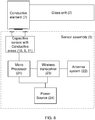
- Fig. 7 shows the components of an exemplary glass removal sensor (1) having a sensor assembly (5) and a conductive element (7) connected to a glass unit (2) through a second conductive element (10) in the form of a metal foil.
- the conductive element comprises two parallel conductive wires (12, 13)
- the sensor assembly comprises an antenna system (22), a microprocessor (21), a wireless transmitter (23) (typically a wireless transceiver) and a power source (24).
- the skilled person will recognize that there are a number of options for implementing wireless communication, including for example transmitter/receiver/transceiver configured to communicate wirelessly using for example Z-Wave, ZigBee, Bluetooth, or Bluetooth Low Energy (BLE) based communication protocols.
- Fig. 8 shows the components of another exemplary glass removal sensor (1) having a sensor assembly (5) and a conductive element (7) connected to a glass unit (2).
- Fig. 9 shows an example of a window comprising a pane (3) and a frame (4) together forming a glass unit (3 and 4).
- a sensor assembly (5) can be seen on the bottom side of the sash (8) of the window.
- the sensor assembly (5) is not visible when the window is closed.
- the rest of the glass removal sensor (1), i.e. further conductive elements are not visible in fig. 6 .
- the sash (8) has a handle (28) for opening and closing the window.
Abstract
Description
- The present disclosure relates to a glass removal sensor for detecting removal of a glass pane, such as a framed glass pane, in a window or a door. The sensor may be configured for sensing removal of the glass pane without breaking the glass.
- A burglar breaking in to a building may gain access to the building in various ways. The windows of a building are naturally a vulnerable area and needs to be protected by an alarm system such that a beak-in is detected. Alarm systems today may detect if a window is open or closed and give off an alarm if the window is opened when it should be closed. This may be achieved by a sensor at the window. An alarm system may further be configured for detecting breaking or shattering of a window in the building. Such detectors work either by sensing the shock or vibrations from breaking glass or by detecting specific frequencies characterizing the sound of breaking glass using a microphone.
- While such sensors do provide good capabilities of detecting a break-in, they do not cover all possible methods used by burglars. One method not covered by such systems is the removal of the entire window glass, either the glass pane or the glass pane with its frame, without breaking it. In this method, the glass pane, optionally the glass pane and its frame, may be pry opened and removed from the sash of the window. Since the window remains closed, the alarm is not set off. Conventional glass break detectors and magnetic sensor for detecting if a window is opened will not detect this type of break-in.
- It is an aim of the present disclosure to provide equipment that prevents burglars from entering a building by removing only the glass pane, or the glass pane with frame, from a window or a door without setting off an alarm of an alarm system. This is provided by the present disclosure relating to a glass removal sensor for detecting removal of a glass unit in a window or a door.
- In a first embodiment the glass removal sensor for detecting removal of a glass unit having a glass pane and optionally a glass frame, in a window, comprises:
- a sensor assembly comprising a capacitive sensor; a first conductive area in connection with the capacitive sensor; and a second conductive area;
- at least a first conductive element arranged, directly or indirectly, between the first conductive area of the sensor assembly, the second conductive area of the sensor assembly and the glass unit of the window or door such that when the glass unit is removed from a sash of the window or door it causes a change of capacitance in the first conductive area relative to the second conductive area of the sensor assembly,
- The inventors have realized that the sensor assembly, preferably a sensor assembly having a thin shape, with an additional capacitive sensor arrangement, can be used to detect the removal of the glass unit from the sash. The sensor assembly may thereby be configured to detect a change of state of the capacitive sensor in response to an externally generated change in capacitance between the first conductive area and a reference point of the sensor assembly. The skilled person would recognize that the capacitive sensor can be implemented in different embodiments. For example, the sensor may be configured to sense an externally generated change in capacitance value between the first conductive area and a second conductive area. This may be achieved in several configurations, as will be demonstrated in the present disclosure. The definitions of the terms 'glass unit' (i.e. glass pane with or without glass frame), 'sash' (i.e. the glass unit and an additional frame, usually the frame of the movable part of a window, or equivalently the outer portion of a door), 'jamb' (head jamb/side jamb/) and 'sill' may be useful for the interpretation of the claimed physical arrangements and functioning of the present glass removal sensor and window.
- The sensor assembly may be a thin, such as thinner than 5 mm, and elongated, assembly. The sensor assembly can be mounted for example on or in the sash of the window or on a door holding a glass pane, i.e. for example on the outside of the movable part of a window, or in the movable part of the door assembly. For example, the sensor assembly can be mounted on the sash using an adhesive film. The first conductive area and/or a second conductive area of the sensor assembly can then be connected, directly or indirectly, to the glass unit, which is a part of the window or door that sometimes can be replaced and sometimes also removed by introducers to break into a building. One advantage of the presently disclosed glass removal sensor is that the glass unit still can be replaced relatively easily. Only the wire or conductive element that is attached to the glass unit needs to be re-attached.
- In one embodiment the first conductive element is arranged between the sensor assembly and the glass unit. The first conductive element may comprise a first wire having first and second wire-end conductive areas. The first wire-end conductive area may be arranged adjacent to the corresponding first conductive area of the sensor assembly. The second wire-end conductive area may be located in the other end of the conductive element towards the glass unit, as shown in
fig. 2 , adjacent to a second conductive element in the form of for example a piece of foil. The second wire may comprise a third wire-end conductive area towards a corresponding second conductive area of the sensor assembly, which may be connected to a ground plane or other reference level. The wire may further comprise a fourth wire-end conductive area in the other end towards the glass unit adjacent to a second conductive element in the form of for example a piece of foil.Fig. 2 shows such an embodiment. The wires may extend for example through a hole in the sash. When the glass unit is in a correctly mounted position in the sash, a glass unit conductive element may be arranged to make a resistive or capacitive short-circuit between the two parallel wires. Removing the entire glass unit from the correctly mounted position will break the short-circuit, thereby also changing the capacitive value at the capacitive sensor. - In a second embodiment, the first conductive element is arranged between the sensor assembly (which is mounted on the sash) and the glass unit. The conductive element makes a resistive or capacitive short circuit between the capacitive sensor and the ground plane or the second conductive area. If the conductive element is removed or broken the short circuit between the capacitive sensor and ground is removed, which causes a change in capacitance measured by the capacitive sensor. If the conductive element is mounted on the glass unit, for example by means of a mechanical wire, in such a way that it is pulled away from the capacitive sensor or such that the connectivity is broken when the glass unit is removed from its correct position, it will break the short-circuit, thereby also changing the capacitive value at the capacitive sensor. This embodiment is shown in
fig. 4 . - The present disclosure further relates to a window and to a door, said window or door comprising;
- a sash (or outer portion in the case of a door);
- a glass unit comprising a glass pane and a glass frame holding the glass pane;
- a glass removal sensor for detecting removal of the glass unit from the sash/outer portion, the glass removal sensor comprising:
- ∘ a sensor assembly comprising a capacitive sensor; a first conductive area in connection with the capacitive sensor; and a second conductive area;
- ∘ at least a first conductive element connected, directly or indirectly, between the first conductive area of the sensor assembly, the second conductive area of the sensor assembly and the glass unit of the window/door.
- The glass removal sensor may be referred to as a window sensor assembly or a door sensor assembly. The glass removal sensor is suitable both for windows that can be opened and windows of the type that cannot be opened, which have a replaceable glass unit, optionally in a frame.
- 'Conductive' in capacitive sensing generally refers to any material capable of propagating an external change of capacitance. A capacitive sensor may be arranged such that an external object approaching it will increase the capacitance between a sensor node or conductive area and a reference point, such as a ground node or a secondary node/area.
- The term 'capacitive connection' is used for a connection between two or more conductive elements separated by an insulator, where the capacitance between the elements is changed due to changes of the insulation layer such as changed size or insulation material characteristics. A change in distance between the elements may also change the capacitance between the elements.
- A 'glass unit' is referred to as a sheet of glass (glass pane), which optionally has a frame holding the glass pane. A glass unit may also be a framed or unframed double-pane or triple-pane glass unit. An example of a 'glass unit' can be found in
fig. 9 . In the example theglass pane 3 and itsframe 4 constitute the glass unit, which may be replaced. - A 'sash' of a window, as used in the present disclosure, is the frame of the part of the window that opens and closes. An example is shown in
fig. 9 , where the 'sash' (8) holds the 'glass unit' (4 and 3) The type of burglary that is prevented by the presently disclosed window sensor is the separation of the 'glass unit' from the 'sash'. The 'sash' is typically the part of the movable part of the window that has a handle (28). A door may be constructed equivalently to a window in the sense that it has an outer portion (corresponding to the 'sash' of a window) holding a glass unit. - A window typically further comprises a fixed frame or framework firmly attached to a wall in a fixed position. In the example of
fig. 9 the fixed frame has a 'head jamb'26, two 'side jambs' 25 and a 'sill' 27. - The presently disclosed glass removal sensor can be used both for windows and doors having a glass unit. Where the description refers to a window specifically, the skilled person will also acknowledge that the technology can be applied to a door.
-
-
Fig. 1 shows a first embodiment of the presently disclosed glass removal sensor with a glass unit and part of a sash. -
Fig. 2 shows the first embodiment of the presently disclosed glass removal sensor with a glass unit. -
Fig. 3 shows a second embodiment of the presently disclosed glass removal sensor with a glass unit and part of a sash. -
Fig. 4 shows the second embodiment of the presently disclosed glass removal sensor with a glass unit. -
Figs. 5A-B show an example of a printed circuit board of an embodiment of the sensor assembly. -
Fig. 6 shows an example of a bottom side of the sensor assembly in the form of a printed circuit board of an elongated sensor assembly. -
Fig. 7 shows the components of an exemplary glass removal sensor having a sensor assembly and a conductive element connected to a glass unit. -
Fig. 8 shows the components of another exemplary glass removal sensor having a sensor assembly and a conductive element connected to a glass unit. -
Fig. 9 shows an example of a window having a glass unit comprising a pane and a frame. A sensor assembly can be seen on the bottom side of the sash of the window. - The present disclosure relates to a glass removal sensor for detecting removal of a glass unit from the sash of a window or a corresponding door frame. The glass removal sensor comprises a sensor assembly having a capacitive sensor and at least a first conductive element connected, directly or indirectly, between the first conductive area of the sensor assembly and the glass unit such that removal of the glass unit from the sash causes a change of capacitance that can be measured by the capacitive sensor. The sensor assembly comprises a capacitive sensor and at least a first conductive area in connection with the capacitive sensor.
- Capacitance describes how the space between two conductors affects an electric field between them. If two conductive plates are placed close to each other and a voltage is applied, an electric field will be generated between the plates. In a capacitive sensor, a surface of the probe corresponds to one of the plates, whereas an external plate or object corresponds to the second plate. When the distance between the two plates is changed, a capacitance change will occur. When this change exceeds a predetermined value, the capacitive sensor generates a signal.
- Several embodiments and configurations of the presently disclosed glass removal sensor may be envisaged. In one embodiment, the glass removal sensor further comprises at least a first wire attached, directly or indirectly, between the first conductive element and the glass unit of the window/door such that when the glass unit is removed from a sash of the window it causes a change of capacitance detected by the capacitive sensor. Examples and embodiments of arrangements allowing the capacitive sensor to detect the removal of the glass unit from the sash are described in detail, including one embodiment in which the first conductive wire and a parallel second conductive wire having wire-end conductive areas in both end are arranged between the sensor assembly and a second conductive element attached to the glass unit, and another embodiment in which the wire is used to pull the first conductive element away from a position adjacent to the sensor assembly when the glass unit is removed from the sash. In one arrangement, the sensor assembly is a very thin assembly, such as having a maximum height of less than 5 mm, which is mounted on a surface of the sash. The thin design of the sensor assembly may allow the sensor assembly to be positioned between the sash and the fixed frame of the window when the window is closed. Alternatively, the sensor assembly can be placed in a groove of the sash or even inside the sash. If the sash is hollow and possibly filled with an insulating material, a cavity can be formed in the sash by removing the insulation so that the sensor assembly can be positioned inside the sash. In any of the above placements, the sensor assembly can be hidden from potential intruders and may not be easily removed. In addition, the sensor assembly is protected from environmental exposure like sunshine and precipitation. The first conductive element may be capacitively connected to the first and second conductive area of the sensor assembly. The first conductive element may comprise two conducting wires with a conductive area in each of the four ends. By placing the conductive element correctly between the sensor assembly and a metal foil, the first and the second capacitive area in the sensor assembly will be capacitively short circuited.
- In a second embodiment the first conductive element may be a single conductive area that capacitively short circuits the first and the second capacitive area in the sensor assembly.
- The first conductive element may be a first piece of foil, such as a metal foil, such as aluminum foil, or copper foil, or steel foil, or gold foil or metal tape, exemplified in
fig. 3 and4 . The first conductive element may be arranged to cover the first conductive area and the second conductive area of the sensor assembly at least partly when the sensor assembly is placed in its position against the sash. The first conductive element may be adapted to be mounted between the sensor assembly and the sash. Preferably, the first conductive element is not attached to the sensor assembly, but may be attachable to the sash. In case the sensor assembly is positioned in a groove of the sash, the first conductive element may accordingly be positioned in the same groove. - In this embodiment, the first conductive element will typically be further connected to an arrangement at or adjacent to the glass unit, which will create the change of capacitance. The glass removal sensor may therefore further comprise a second conductive element attachable to the glass unit. An example of such a second conductive element (10) is shown in
fig. 2 in the form of a metal foil. The second conductive element may be a piece of foil, such as a metal foil, such as aluminum foil, or copper foil, or steel foil, or gold foil or metal tape. The first and second conductive areas may be connected using the first wire and a parallel second wire and a second conductive element connecting the first and second wires. - In a second embodiment, the first wire may by any wire and not necessarily a conducting wire. The first wire may be attached to the glass unit, optionally attached to an attachment element which is attached to the glass unit, and configured such that when the glass unit is removed from the sash, the first wire pulls the first conductive element away from the first conductive area. For example, the first conductive element may be pulled through a hole in the sash. The capacitive sensor will detect a change in the measured capacitive value as a consequence of the first conductive element being removed from the conductive area.
- The sensor assembly, which preferably is an elongated and thin sensor assembly, may further comprise:
- a microprocessor configured to detect the detect the change of capacitance;
- an antenna system for transmitting a signal indication if the window/door glass is removed from the window/door (or replaced), or transmitting a signal as long as the window/door glass is not removed from the window/door;
- a wireless transceiver/transmitter configured to receive a signal from the microprocessor identifying the change of capacitance; and
- a power source for providing electric power to the glass removal sensor.
- The microprocessor may be any kind of processing unit implemented in a circuit configured to: detect one or more changes of state of the capacitive sensor and optionally other sensors.
- In order to fit inside narrow elongated voids and cavities the maximum height/thickness of the sensor assembly should be kept to a minimum, i.e. preferably less than 5 mm, more preferably less than 4.5 mm, yet more preferably less than 4 mm, or less than 3.5 mm, even more preferably less than 3 mm, yet more preferably less than 2.5 mm, even more preferably less than 2 mm, possibly less than 1.5 mm or less than 1 mm.
- The power source may be an ultrathin battery having a thickness below 2.0 mm, preferably less than 1.0 mm, even more preferably less than 0.5 mm. In order to have a certain minimum battery life, the battery may be flat, thin and elongated. This may result in the sensor assembly having a minimum length of 100 mm.
- The sensor assembly may have at least a first conductive area separated from the ground plane by a first insulation layer, preferably wherein the first insulation layer is integrated in the bottom side of the sensor assembly, and/or wherein the second conductive area is separated from the ground plane by a second insulation barrier. Preferably, the first and second conductive areas are arranged in the same PCB layer, which is typically an outer layer, arranged towards the first conductive element. The first and second conductive areas may thereby form two parallel capacitors with one or several metal foils positioned at the areas. A piece of tape, coating or layer of enamel paint may serve as an insulation layer between the first and second conductive areas and the metal foil(s). The first and the second conductive areas may be part of a PCB, wherein the PCB may constitute the bottom side of the sensor assembly.
Fig. 5A shows an embodiment of an elongated sensor assembly with double conductive areas on the bottom side connected to a first capacitive sensor, a ground plane and a third conductive area connected to a second capacitive sensor. The assembly may have one or several conductive areas connected to a capacitive sensor. The capacitive sensor referred to is configured to detect changes in response to an externally generated change in conductivity between two or more conductive areas, wherein one area may be connected to the capacitive sensor and the other conductive area is connected to ground or another reference. - The sensor assembly may be further configured for detecting if the window is open or closed. The sensor assembly may therefore further comprise at least one sensor switch, such as a magnetically activated reed switch, configured to detect a given state and a change of state between the given state and at least one other state. The at least one sensor switch may be configured to detect whether a window or door is open or closed.
- The arrangements of the first conductive element, and/or the second conductive element in relation to the sensor assembly and the glass unit may be used to detect the removal of the glass unit from the sash. In one embodiment, the capacitance between the first conductive area and a reference point of the sensor assembly changes due to a broken electrical contact between for example the two wires of the first conductive element. The change of capacitance could also be a change caused by a broken electrical or capacitive contact between the first and/or second or due to a change in distance between the first conductive element and the first conductive area, or due to a change in relative position of the first and second conductive elements. The change of capacitance registered by the capacitive sensor may also be caused by breaking the first wire and/or the second wire when the glass unit is removed from the sash.
- As would be appreciated by the skilled person, the conductive element(s) and wire(s) may take a number of shapes and may be made of different materials. The first and/or second may be electrically and/or magnetically conductive elements. The elements can be implemented in the form of conductive paint. For example, a layer of conductive paint can be applied to the glass unit and a corresponding layer of paint on the sash. A conductive paint is easy to apply. If a wire is used, an end of the wire can be painted or positioned in the wet paint and when the paint has dried, the wire is firmly connected to the paint and there is a conductive connection between the paint and the end of the wire. The first and/or second conductive elements may alternatively be configured for attachment to the sash of the window using an adhesive, or Velcro, or single-sided tape, or double-sided tape, or glue.
- The first and/or second conductive element may be mounted on a piece of foam, preferably wherein the foam has an adhesive side, such that the foam is located between the conductive element and the sash. The thickness of the foam may be less than 10 mm, preferably less than 5 mm, more preferably less than 3 mm, even more preferably less than 1 mm.
- The first and second wires may be made of electrically conductive material, such as copper, or steel, or brass, or aluminum, or gold. In arrangements where the wire(s) are only used to pull for example the first conductive element away from the conductive area of the sensor assembly when the glass unit is removed, the wire(s) do not necessarily have to be conductive.
- The first and/or second wire(s) can also be a metal pin or nail, optionally with a pointed end. Such a metal pin can protrude from the rear side of the sensor assembly. If the spacer of a double-pane or a triple-pane is partly made of metal, the metal pin can be arranged to extend through the case to come in close proximity of the spacer as a capacitive element.
- The present disclosure further relates to a window comprising;
- a sash;
- a glass unit comprising a glass pane and optionally a glass frame holding the glass pane;
- a glass removal sensor for detecting removal of the glass unit from the sash, the glass removal sensor comprising:
- ∘ a sensor assembly comprising a capacitive sensor; a first conductive area in connection with the capacitive sensor; and a second conductive area;
- ∘ at least a first conductive element connected, directly or indirectly, between the first conductive area of the sensor assembly, the second conductive area of the sensor assembly and the glass unit of the window.
- The present disclosure further relates to a door comprising;
- an outer portion;
- a glass unit comprising a glass pane and optionally a glass frame holding the glass pane;
- a glass removal sensor for detecting removal of the glass unit from the outer portion, the glass removal sensor comprising:
- ∘ a sensor assembly comprising a capacitive sensor; a first conductive area in connection with the capacitive sensor; and a second conductive area in connection with a capacitive sensor reference level, such as the ground plane;
- ∘ at least a first conductive element connected, directly or indirectly, between the first conductive area of the sensor assembly, the second conductive area of the sensor assembly and the glass unit of the door.
- The glass removal sensor may be any embodiment of the presently disclosed glass removal sensor, comprising any embodiment of the presently disclosed sensor assembly. The window or door may further comprise a fixed frame or framework, which can be mounted in the window opening of a building, for example a frame as shown in
fig. 9 . The window may thereby be sold and delivered as a complete unit, wherein the sensor assembly may for example be integrated into the sash. The glass removal sensor may serve both as a wireless alarm of the type that indicates whether the window is opened or closed and an alarm indicating when the glass unit is removed from the sash. - The sash may have a through hole or a slot, through which a first and/or second wire of the glass removal sensor can be inserted to connect the sensor assembly and the glass unit. The window may be of any type that has a sash holding a glass unit as defined in the present disclosure. Types of windows include an awning window, a casement window, a double hung window, a gliding window, a double hung window, and single hung window. The glass removal sensor can be installed in any of these window types. The window can also be of the type that cannot be opened, still having a replaceable glass unit in a frame.
- The invention will in the following be described in greater detail with reference to the accompanying drawings. The drawings are exemplary and are intended to illustrate some of the features of the presently disclosed glass removal sensor and are not to be construed as limiting to the presently disclosed invention.
-
Fig. 1 shows a first embodiment of the presently disclosed glass removal sensor (1) with a glass unit (2) and sash (8). The glass unit (2) has a pane (3) and a glass frame (4). The sash (8) is shown as two pieces, which are, however, part of the same sash (8). Two different views of the sash (8) are shown to illustrate how the sensor assembly (5) may be located on one side, in this case the side on the opposite side of the glass unit (2), whereas the second conductive element (10) is attached to the glass unit (2). In the example the sensor assembly (5) is placed such that the capacitive sensor (16), or at least the first conductive area (6) (preferably there are two conductive areas (6, 11)) is located adjacent to the first and third wire-end conducting areas (14, 15) of the first conductive element (7). A major part of the visible side of the sensor assembly may be ground, which is typically separated from the first conductive area (6) by means of for example a minimum distance or a barrier. The ground may constitute the second conductive area (11), as shown in the figure. The first conductive area (6) may be positioned against one of the two wire-end conductive areas (14, 15), and the second conductive area (11) may be positioned against the second wire-end conductive area (15). Conductive first and second wires (12, 13) extend through a hole (9) in the sash (8). The wires may be attached to two different conductive areas, a first conductive area (6) and a second conductive area (11) (which may be ground as shown infig. 1 ), of the sensor assembly. The wires are connected to a second conductive element (10) in the form of a foil (10) with second and fourth wire-end conducting areas (14, 15) mounted on the sash (8) on the side facing the glass unit (2). Removal of the glass unit (2) from the sash (8) causes a change of capacitive load, which is sensed by the capacitive sensor (16). -
Fig. 2 shows the first embodiment of the presently disclosed glass removal sensor with a glass unit (2). In this embodiment the first conductive element (7) is arranged between the sensor assembly and the glass unit (5). The first conductive element comprises a first wire (12) having first and second wire-end conductive areas (14). The first wire-end conductive area (14) is arranged towards the corresponding first conductive area (6) of the sensor assembly. The second wire-end conductive area (14) is arranged towards the second conductive element (10). The second wire (13) comprises a third wire-end conductive area (15) towards a corresponding second conductive area (11) of the sensor assembly, which is connected to ground. The wire further comprises a fourth wire-end conductive area (15) in the other end towards the glass unit (15), the area located towards the second conductive element (10). -
Fig. 3 shows a second embodiment of the presently disclosed glass removal sensor (1) with a glass unit (2) and sash (8). The glass unit (2) has a pane (3) and a glass frame (4). In the example the sensor assembly (5) is placed such that the conductive area (6), and the ground area, which may be the second conductive area (11), are located towards the first conductive element (7) in the form a foil. In the example the foil is not attached to the sash (8). A wire (12) is attached to the first conductive element (7) through a hole (9) in the sash (8). The opposite end of the wire (12) is attached to an attachment element (15) in the form of a foil, which is attached to the frame (4) of the glass unit (2). The wire may be attached to the glass unit (2) in any suitable way, using any suitable attachment element. Removal of the glass unit (2) from the sash (8) causes the wire to pull the first conductive element (7) through the hole (9). When the first conductive element (7) is pulled away from the conductive area (6), it causes a change of capacitive load, which is sensed by the capacitive sensor (16). The first conductive element (7) covers at least a part of the first conductive area (6) and at least a part of the second conductive area (11). -
Fig. 4 shows the second embodiment of the presently disclosed glass removal sensor with a glass unit (2). The first conductive element (7) is arranged between the sensor assembly and the glass unit (2). The conductive element (7) makes a resistive or capacitive short circuit between the first conductive area (6) and the second conductive area (11). If the conductive element (7) is removed or broken the connection between the capacitive sensor and ground is removed, which causes a change in capacitance measured by the capacitive sensor. The conductive element (7) is connected to the glass unit (2) by means of a physical wire (12). -
Fig. 5A shows an embodiment of an elongated sensor assembly (5) with a first conductive area (6) and a ground plane (18) on the bottom side of the assembly. In the example the sensor assembly further comprises additional conductive areas (6'). The assembly comprises a capacitive sensor (16). The assembly has two longer edges (19).Fig. 5B is a side view of the elongated sensor assembly (5). The elongated sensor assembly has a thickness h. It can be seen that the conductive areas (6) are part of a PCB (20) which constitutes the bottom side (20) in this embodiment. -
Fig. 6 shows an example bottom side in the form of a printed circuit board of an elongated sensor assembly. The bottom side (backside) of the printed circuit board has a first conductive area (6) in the form of a rectangular area. A first rectangular isolation barrier (17) separates the first conductive area (6) from the ground plane (18). The capacitive sensor (16) is placed on the top side of the PCB and is not visible infig. 6 . In the example the sensor assembly further comprises additional conductive areas (6'), which may or may not be used as part of the glass removal sensor. -
Fig. 7 shows the components of an exemplary glass removal sensor (1) having a sensor assembly (5) and a conductive element (7) connected to a glass unit (2) through a second conductive element (10) in the form of a metal foil. The conductive element comprises two parallel conductive wires (12, 13) The sensor assembly comprises an antenna system (22), a microprocessor (21), a wireless transmitter (23) (typically a wireless transceiver) and a power source (24). The skilled person will recognize that there are a number of options for implementing wireless communication, including for example transmitter/receiver/transceiver configured to communicate wirelessly using for example Z-Wave, ZigBee, Bluetooth, or Bluetooth Low Energy (BLE) based communication protocols.Fig. 8 shows the components of another exemplary glass removal sensor (1) having a sensor assembly (5) and a conductive element (7) connected to a glass unit (2). -
Fig. 9 shows an example of a window comprising a pane (3) and a frame (4) together forming a glass unit (3 and 4). A sensor assembly (5) can be seen on the bottom side of the sash (8) of the window. The sensor assembly (5) is not visible when the window is closed. The rest of the glass removal sensor (1), i.e. further conductive elements are not visible infig. 6 . The sash (8) has a handle (28) for opening and closing the window. -
- 1 - glass removal sensor
- 2 - glass unit
- 3 - glass pane
- 4 - glass frame
- 5 - sensor assembly
- 6 - first conductive area (of sensor assembly)
- 7 - first conductive element (in the example having two wires (12, 13))
- 8 - sash
- 9 - through-hole/slot in the sash
- 10 - second conductive element
- 11 - second conductive area (of sensor assembly)
- 12 - first wire
- 13 - second wire
- 14 - first and second wire-end conducting areas (associated with first wire)
- 15 - third and fourth wire-end conducting areas (associated with second wire)
- 16 - capacitive sensor
- 17 - isolation barrier
- 18 - ground plane
- 19 - long edge
- 20 - PCB / bottom side
- 21 - microprocessor
- 22 - antenna system
- 23 - wireless transmitter/transceiver
- 24 - power source
- 25 - side jambs
- 26 - head jamb
- 27 - sill
- 28 - handle
- 29 - attachment element (for attachment to the glass unit)
-
- 1. A glass removal sensor for detecting removal of a glass unit having a glass pane and optionally a glass frame, in a window or a door, said glass removal sensor comprising:
- a sensor assembly comprising a capacitive sensor; a first conductive area in connection with the capacitive sensor; and a second conductive area;
- at least a first conductive element connected, directly or indirectly, between the first conductive area of the sensor assembly, the second conductive area of the sensor assembly and the glass unit of the window or door such that when the glass unit is removed from a sash of the window or door it causes a change of capacitance in the first conductive area relative to the second conductive area of the sensor assembly,
- 2. The glass removal sensor according to
item 1, wherein the second conductive area is connected to ground or to a reference point of the sensor assembly. - 3. The glass removal sensor according to any of the preceding items, further comprising at least a first wire attachable, directly or indirectly, between the first conductive element and the glass unit of the window or door such that when the glass unit is removed from the sash it causes a change of capacitance in the first conductive area.
- 4. The glass removal sensor according to any of the preceding items, wherein the first conductive element is a first piece of foil, such as a metal foil, such as aluminum foil, or copper foil, or steel foil, or gold foil or metal tape.
- 5. The glass removal sensor according to any of the preceding items, wherein the first conductive element is arranged to cover the first conductive area and the second conductive area of the sensor assembly.
- 6. The glass removal sensor according to any of the preceding items, wherein the first conductive element is attachable to the sash.
- 7. The glass removal sensor according to any of the preceding items, wherein the sensor assembly has a maximum height of less than 5 mm.
- 8. The glass removal sensor according to any of the preceding items, wherein the sensor assembly is configured to detect a change of state of the capacitive sensor in response to an externally generated change in capacitance between the first conductive area and a ground plane of the sensor assembly or between the first conductive area and a second conductive area of the sensor assembly.
- 9. The glass removal sensor according to any of the preceding items, wherein the sensor assembly is adapted to be mounted on an outside or inside of the sash.
- 10. The glass removal sensor according to
items - 11. The glass removal sensor according to any of the preceding items, further comprising a second conductive element attachable to the glass unit.
- 12. The glass removal sensor according to
item 11, wherein the second conductive element is a second piece of foil, such as a metal foil, such as aluminum foil, or copper foil, or steel foil, or gold foil or metal tape. - 13. The glass removal sensor according to
item 11, wherein the first conductive element comprises a first wire and a parallel second wire. - 14. The glass removal sensor according to any of items 11-13, wherein the first wire comprises a first wire-end conductive area towards the first conductive area of the sensor assembly, and wherein the first wire comprises a second wire-end conductive area towards the glass unit.
- 15. The glass removal sensor according to any of items 11-14, wherein the second wire comprises a third wire-end conductive area towards the second conductive area of the sensor assembly, and wherein the second wire comprises a fourth wire-end conductive area towards the glass unit.
- 16. The glass removal sensor according to
item 15, wherein the second conductive element is arranged in close proximity but not attached to the second and fourth wire-end conductive areas. - 17. The glass removal sensor according to any of the preceding items, wherein the first wire is attached to the glass unit, optionally attached to an attachment element attached to the glass unit and configured such that when the glass unit is removed from the sash, the first conductive element is pulled away from the first conductive area and the second conductive area.
- 18. The glass removal sensor according to
item 17, wherein the first conductive element is arranged on, and at least partly covering, the first conductive area and the second conductive area. - 19. The glass removal sensor according to any of the preceding items, further comprising:
- a microprocessor configured to detect the detect the change of capacitance;
- an antenna system for transmitting a signal indication that the glass unit is removed if the glass pane is removed from the sash, or transmitting a signal as long as the glass unit is not removed from the sash;
- a wireless transmitter configured to receive a signal from the microprocessor identifying the change of capacitance; and
- a power source for providing electric power to the glass removal sensor.
- 20. The glass removal sensor according to any of the preceding items, wherein the ground plane and the first conductive area are part of a PCB, wherein the PCB constitutes the bottom side of the sensor assembly.
- 21. The glass removal sensor according to any of the preceding items, wherein the capacitance of the first conductive element changes due to a broken electrical or capacitive contact between the first wire and second wire, or due to a broken electrical or capacitive contact between the first and second conductive area.
- 22. The glass removal sensor according to any of the preceding items, wherein the first and/or second conductive elements is/are electrically and/or magnetically conductive element(s).
- 23. The glass removal sensor according to any of the preceding items, wherein the first and/or second conductive elements is/are (a) conductive paint.
- 24. The glass removal sensor according to
item 13, wherein the first and second wires are made of electrically conductive material, such as copper, or steel, or brass, or aluminum, or gold. - 25. The glass removal sensor according to any of the preceding items, wherein the first and/or second conductive element is configured for attachment to the sash using an adhesive, or Velcro, or single-sided tape, or double-sided tape, glue, nail, screw, or staple, or by casting the the first and/or second conductive element into the sash.
- 26. The glass removal sensor according to any of the preceding items, wherein the window is an openable window and wherein the sensor assembly is further configured for detecting if the window is open or closed.
- 27. A window comprising;
- a sash;
- a glass unit comprising a glass pane and optionally a glass frame holding the glass pane;
- a glass removal sensor for detecting removal of the glass unit from the sash, the glass removal sensor comprising:
- ∘ a sensor assembly comprising a capacitive sensor; a first conductive area in connection with the capacitive sensor; and a second conductive area;
- ∘ at least a first conductive element connected, directly or indirectly, between the first conductive area of the sensor assembly, the second conductive area of the sensor assembly and the glass unit of the window.
- 28. The window according to
item 27, wherein the glass removal sensor is the glass removal sensor according to any of items 1-26. - 29. The window according to any of items 27-28, wherein the sensor assembly is mounted in the sash or on the sash, such in a groove or indentation in the sash.
- 30. The window according to any of items 27-29, wherein the sash has a through hole or a slot for receiving a first and/or second wire of the glass removal sensor connecting the sensor assembly and the glass unit.
- 31. The window according to any of items 27-30, wherein the first and/or second is mounted on a piece of foam, preferably wherein the foam has an adhesive side, such that the foam is located between the conductive element and the sash.
- 32. The window according to item 31, wherein the thickness of the foam is less than 10 mm, preferably less than 5 mm, more preferably less than 3 mm, even more preferably less than 1 mm.
- 33. A door comprising;
- an outer portion;
- a glass unit comprising a glass pane and optionally a glass frame holding the glass pane;
- a glass removal sensor for detecting removal of the glass unit from the outer portion, the glass removal sensor comprising:
- ∘ a sensor assembly comprising a capacitive sensor; a first conductive area in connection with the capacitive sensor; and a second conductive area;
- ∘ at least a first conductive element connected, directly or indirectly, between the first conductive area of the sensor assembly, the second conductive area of the sensor assembly and the glass unit of the door.
- 34. Use of a glass removal sensor according to any of items 1-26 for detecting removal of a glass unit in a window or a door.
- 35. Use according to item 34, wherein the window is a window according to any of items 27-32 and/or wherein the door is a door according to item 33.
- 36. A window or door comprising;
- a sash;
- a glass unit comprising a glass pane and optionally a glass frame holding the glass pane;
- at least a first conductive element comprising a first wire and a parallel second wire connected to a second conductive element attached to the glass unit, wherein the first wire has a first wire-end area arranged on the outside of the sash, and the second wire has a third wire-end area arranged on the outside of the sash
or- at least a first conductive element arranged on the outside of the sash;
- a first wire attached to the first conductive element and the glass unit,
A door/window may also be sold and delivered as a security-prepared door/window where the conductive element and glass unit metal foil may be pre-mounted and marking may indicate where the sensor assembly should be placed.
Claims (15)
- A glass removal sensor for detecting removal of a glass unit having a glass pane and optionally a glass frame, in a window or a door, said glass removal sensor comprising:- a sensor assembly comprising a capacitive sensor; a first conductive area in connection with the capacitive sensor; and a second conductive area;- at least a first conductive element connected, directly or indirectly, between the first conductive area of the sensor assembly, the second conductive area of the sensor assembly and the glass unit of the window or door such that when the glass unit is removed from a sash of the window or door it causes a change of capacitance in the first conductive area relative to the second conductive area of the sensor assembly,wherein the sensor assembly is configured to detect the removal of the glass unit from the sash of the window or door as the change of capacitance detected by the capacitive sensor.
- The glass removal sensor according to claim 1, wherein the second conductive area is connected to ground or to a reference point of the sensor assembly.
- The glass removal sensor according to any of the preceding claims, further comprising at least a first wire attachable, directly or indirectly, between the first conductive element and the glass unit of the window or door such that when the glass unit is removed from the sash it causes a change of capacitance in the first conductive area.
- The glass removal sensor according to any of the preceding claims, wherein the first conductive element is a first piece of foil, such as a metal foil, such as aluminum foil, or copper foil, or steel foil, or gold foil or metal tape.
- The glass removal sensor according to any of the preceding claims, wherein the first conductive element is arranged to cover the first conductive area and the second conductive area of the sensor assembly.
- The glass removal sensor according to any of the preceding claims, wherein the sensor assembly has a maximum height of less than 5 mm.
- The glass removal sensor according to any of the preceding claims, further comprising a second conductive element attachable to the glass unit.
- The glass removal sensor according to any of the preceding claims, wherein the first conductive element comprises a first wire and a parallel second wire.
- The glass removal sensor according to any of claims 8, wherein the first wire comprises a first wire-end conductive area towards the first conductive area of the sensor assembly, and wherein the first wire comprises a second wire-end conductive area towards the glass unit.
- The glass removal sensor according to any of claims 8-9, wherein the second wire comprises a third wire-end conductive area towards the second conductive area of the sensor assembly, and wherein the second wire comprises a fourth wire-end conductive area towards the glass unit.
- The glass removal sensor according to any of the preceding claims, wherein the first wire is attached to the glass unit, optionally attached to an attachment element attached to the glass unit and configured such that when the glass unit is removed from the sash, the first conductive element is pulled away from the first conductive area and the second conductive area.
- The glass removal sensor according to any of the preceding claims, wherein the ground plane and the first conductive area are part of a PCB, wherein the PCB constitutes the bottom side of the sensor assembly.
- A window comprising;- a sash;- a glass unit comprising a glass pane and optionally a glass frame holding the glass pane;wherein the glass unit is mounted in the sash; and- a glass removal sensor for detecting removal of the glass unit from the sash, the glass removal sensor comprising:∘ a sensor assembly comprising a capacitive sensor; a first conductive area in connection with the capacitive sensor; and a second conductive area;∘ at least a first conductive element connected, directly or indirectly, between the first conductive area of the sensor assembly, the second conductive area of the sensor assembly and the glass unit of the window.
- A door comprising;- an outer portion;- a glass unit comprising a glass pane and optionally a glass frame holding the glass pane;wherein the glass unit is mounted in the outer portion; and- a glass removal sensor for detecting removal of the glass unit from the outer portion, the glass removal sensor comprising:∘ a sensor assembly comprising a capacitive sensor; a first conductive area in connection with the capacitive sensor; and a second conductive area;∘ at least a first conductive element connected, directly or indirectly, between the first conductive area of the sensor assembly, the second conductive area of the sensor assembly and the glass unit of the door.
- A window or door comprising;- a sash;- a glass unit comprising a glass pane and optionally a glass frame holding the glass pane;wherein the glass unit is mounted in the sash; and- at least a first conductive element comprising a first wire and a parallel second wire connected to a second conductive element attached to the glass unit, wherein the first wire has a first wire-end area arranged on the outside of the sash, and the second wire has a third wire-end area arranged on the outside of the sashwherein the sash has an indication for a placement of a sensor assembly according to any of claims 1-12, such that a first capacitive area and a second capacitive area of the sensor assembly coincide with the first wire-end area and the second wire-end area,
or- at least a first conductive element arranged on the outside of the sash;- a first wire attached to the first conductive element and the glass unit,wherein the sash has an indication for a placement of a sensor assembly according to any of claims 1-12, such that a first capacitive area and a second capacitive area are at least partly covered by the first conductive element.
Applications Claiming Priority (1)
| Application Number | Priority Date | Filing Date | Title |
|---|---|---|---|
| EP18215562 | 2018-12-21 |
Publications (2)
| Publication Number | Publication Date |
|---|---|
| EP3670811A1 true EP3670811A1 (en) | 2020-06-24 |
| EP3670811B1 EP3670811B1 (en) | 2022-10-05 |
Family
ID=64901414
Family Applications (1)
| Application Number | Title | Priority Date | Filing Date |
|---|---|---|---|
| EP19218762.3A Active EP3670811B1 (en) | 2018-12-21 | 2019-12-20 | Glass removal sensor for detecting removal of a pane from a window or door |
Country Status (1)
| Country | Link |
|---|---|
| EP (1) | EP3670811B1 (en) |
Citations (4)
| Publication number | Priority date | Publication date | Assignee | Title |
|---|---|---|---|---|
| DE2809436A1 (en) * | 1978-03-04 | 1979-09-06 | Gabriele Koechlin | Security system for plate glass - uses conducting outer mounting strip to provide capacitive sensing detector |
| GB2186408A (en) * | 1986-02-07 | 1987-08-12 | Bennet Hugh | Security system for glazed units |
| GB2201277A (en) * | 1987-02-19 | 1988-08-24 | Hickman James A A | Glazing unit alarm system |
| US20180268671A1 (en) * | 2013-09-19 | 2018-09-20 | Sensative Ab | Elongated wireless sensor assembly |
-
2019
- 2019-12-20 EP EP19218762.3A patent/EP3670811B1/en active Active
Patent Citations (4)
| Publication number | Priority date | Publication date | Assignee | Title |
|---|---|---|---|---|
| DE2809436A1 (en) * | 1978-03-04 | 1979-09-06 | Gabriele Koechlin | Security system for plate glass - uses conducting outer mounting strip to provide capacitive sensing detector |
| GB2186408A (en) * | 1986-02-07 | 1987-08-12 | Bennet Hugh | Security system for glazed units |
| GB2201277A (en) * | 1987-02-19 | 1988-08-24 | Hickman James A A | Glazing unit alarm system |
| US20180268671A1 (en) * | 2013-09-19 | 2018-09-20 | Sensative Ab | Elongated wireless sensor assembly |
Also Published As
| Publication number | Publication date |
|---|---|
| EP3670811B1 (en) | 2022-10-05 |
Similar Documents
| Publication | Publication Date | Title |
|---|---|---|
| EP3053152B1 (en) | Slim wireless window opening detector | |
| CN112189223A (en) | Security alarm system including RFID tag | |
| CA2463702A1 (en) | Wireless security sensor systems for windows and doors | |
| US11170617B2 (en) | Elongated wireless sensor assembly | |
| AU2013328266B2 (en) | Alarm system for rolling shutters | |
| EP0609098A1 (en) | An assembly of a detector and a wing or sash and a frame | |
| US10557877B2 (en) | Alarm pane assembly | |
| US10234307B1 (en) | Slot-based fenestration unit monitoring apparatus and methods | |
| EP3670811B1 (en) | Glass removal sensor for detecting removal of a pane from a window or door | |
| US11004313B2 (en) | Alarm screen with embedded wireless transmitter | |
| US10317247B1 (en) | Fenestration unit monitoring apparatus with tethers and methods | |
| WO2001004857A1 (en) | Glass-mounted sensor | |
| JP4413073B2 (en) | Electric circuit abnormality detection device | |
| WO2001022378A1 (en) | Glass sensor | |
| GB2040142A (en) | Transponder type burglar alarm operated by vibration | |
| EP3987256B1 (en) | Sensor device comprising a vibration detector | |
| CN214955234U (en) | Window with entrance safety monitoring function | |
| WO2004019062A2 (en) | Security apparatus for the detection of approaching objects | |
| KR20030090315A (en) | Apparatus for preserving of glass door and method for manufacturing glass door | |
| US20110173889A1 (en) | Device for detecting a break-in attempt on an opening moveably mounted relative to a frame | |
| KR20200028064A (en) | Door opening and closing confirmation apparatus using ceramic membrane pressure sensor | |
| JP2003187341A (en) | Burglar prevention device | |
| JP2006185401A (en) | Crime-preventing destruction vibration sensor | |
| JP2004085327A (en) | Living body detector |
Legal Events
| Date | Code | Title | Description |
|---|---|---|---|
| PUAI | Public reference made under article 153(3) epc to a published international application that has entered the european phase |
Free format text: ORIGINAL CODE: 0009012 |
|
| STAA | Information on the status of an ep patent application or granted ep patent |
Free format text: STATUS: THE APPLICATION HAS BEEN PUBLISHED |
|
| AK | Designated contracting states |
Kind code of ref document: A1 Designated state(s): AL AT BE BG CH CY CZ DE DK EE ES FI FR GB GR HR HU IE IS IT LI LT LU LV MC MK MT NL NO PL PT RO RS SE SI SK SM TR |
|
| AX | Request for extension of the european patent |
Extension state: BA ME |
|
| STAA | Information on the status of an ep patent application or granted ep patent |
Free format text: STATUS: REQUEST FOR EXAMINATION WAS MADE |
|
| RBV | Designated contracting states (corrected) |
Designated state(s): AL AT BE BG CH CY CZ DE DK EE ES FI FR GB GR HR HU IE IS IT LI LT LU LV MC MK MT NL NO PL PT RO RS SE SI SK SM TR |
|
| 17P | Request for examination filed |
Effective date: 20201223 |
|
| GRAP | Despatch of communication of intention to grant a patent |
Free format text: ORIGINAL CODE: EPIDOSNIGR1 |
|
| STAA | Information on the status of an ep patent application or granted ep patent |
Free format text: STATUS: GRANT OF PATENT IS INTENDED |
|
| INTG | Intention to grant announced |
Effective date: 20220517 |
|
| GRAS | Grant fee paid |
Free format text: ORIGINAL CODE: EPIDOSNIGR3 |
|
| GRAA | (expected) grant |
Free format text: ORIGINAL CODE: 0009210 |
|
| STAA | Information on the status of an ep patent application or granted ep patent |
Free format text: STATUS: THE PATENT HAS BEEN GRANTED |
|
| AK | Designated contracting states |
Kind code of ref document: B1 Designated state(s): AL AT BE BG CH CY CZ DE DK EE ES FI FR GB GR HR HU IE IS IT LI LT LU LV MC MK MT NL NO PL PT RO RS SE SI SK SM TR |
|
| REG | Reference to a national code |
Ref country code: GB Ref legal event code: FG4D |
|
| REG | Reference to a national code |
Ref country code: CH Ref legal event code: EP |
|
| REG | Reference to a national code |
Ref country code: AT Ref legal event code: REF Ref document number: 1522860 Country of ref document: AT Kind code of ref document: T Effective date: 20221015 |
|
| REG | Reference to a national code |
Ref country code: IE Ref legal event code: FG4D |
|
| REG | Reference to a national code |
Ref country code: DE Ref legal event code: R096 Ref document number: 602019020248 Country of ref document: DE |
|
| REG | Reference to a national code |
Ref country code: LT Ref legal event code: MG9D |
|
| REG | Reference to a national code |
Ref country code: NO Ref legal event code: T2 Effective date: 20221005 |
|
| REG | Reference to a national code |
Ref country code: SE Ref legal event code: TRGR |
|
| REG | Reference to a national code |
Ref country code: NL Ref legal event code: MP Effective date: 20221005 |
|
| REG | Reference to a national code |
Ref country code: AT Ref legal event code: MK05 Ref document number: 1522860 Country of ref document: AT Kind code of ref document: T Effective date: 20221005 |
|
| PG25 | Lapsed in a contracting state [announced via postgrant information from national office to epo] |
Ref country code: NL Free format text: LAPSE BECAUSE OF FAILURE TO SUBMIT A TRANSLATION OF THE DESCRIPTION OR TO PAY THE FEE WITHIN THE PRESCRIBED TIME-LIMIT Effective date: 20221005 |
|
| PG25 | Lapsed in a contracting state [announced via postgrant information from national office to epo] |
Ref country code: PT Free format text: LAPSE BECAUSE OF FAILURE TO SUBMIT A TRANSLATION OF THE DESCRIPTION OR TO PAY THE FEE WITHIN THE PRESCRIBED TIME-LIMIT Effective date: 20230206 Ref country code: LT Free format text: LAPSE BECAUSE OF FAILURE TO SUBMIT A TRANSLATION OF THE DESCRIPTION OR TO PAY THE FEE WITHIN THE PRESCRIBED TIME-LIMIT Effective date: 20221005 Ref country code: FI Free format text: LAPSE BECAUSE OF FAILURE TO SUBMIT A TRANSLATION OF THE DESCRIPTION OR TO PAY THE FEE WITHIN THE PRESCRIBED TIME-LIMIT Effective date: 20221005 Ref country code: ES Free format text: LAPSE BECAUSE OF FAILURE TO SUBMIT A TRANSLATION OF THE DESCRIPTION OR TO PAY THE FEE WITHIN THE PRESCRIBED TIME-LIMIT Effective date: 20221005 Ref country code: AT Free format text: LAPSE BECAUSE OF FAILURE TO SUBMIT A TRANSLATION OF THE DESCRIPTION OR TO PAY THE FEE WITHIN THE PRESCRIBED TIME-LIMIT Effective date: 20221005 |
|
| PGFP | Annual fee paid to national office [announced via postgrant information from national office to epo] |
Ref country code: CH Payment date: 20230201 Year of fee payment: 4 |
|
| PG25 | Lapsed in a contracting state [announced via postgrant information from national office to epo] |
Ref country code: RS Free format text: LAPSE BECAUSE OF FAILURE TO SUBMIT A TRANSLATION OF THE DESCRIPTION OR TO PAY THE FEE WITHIN THE PRESCRIBED TIME-LIMIT Effective date: 20221005 Ref country code: PL Free format text: LAPSE BECAUSE OF FAILURE TO SUBMIT A TRANSLATION OF THE DESCRIPTION OR TO PAY THE FEE WITHIN THE PRESCRIBED TIME-LIMIT Effective date: 20221005 Ref country code: LV Free format text: LAPSE BECAUSE OF FAILURE TO SUBMIT A TRANSLATION OF THE DESCRIPTION OR TO PAY THE FEE WITHIN THE PRESCRIBED TIME-LIMIT Effective date: 20221005 Ref country code: IS Free format text: LAPSE BECAUSE OF FAILURE TO SUBMIT A TRANSLATION OF THE DESCRIPTION OR TO PAY THE FEE WITHIN THE PRESCRIBED TIME-LIMIT Effective date: 20230205 Ref country code: HR Free format text: LAPSE BECAUSE OF FAILURE TO SUBMIT A TRANSLATION OF THE DESCRIPTION OR TO PAY THE FEE WITHIN THE PRESCRIBED TIME-LIMIT Effective date: 20221005 Ref country code: GR Free format text: LAPSE BECAUSE OF FAILURE TO SUBMIT A TRANSLATION OF THE DESCRIPTION OR TO PAY THE FEE WITHIN THE PRESCRIBED TIME-LIMIT Effective date: 20230106 |
|
| REG | Reference to a national code |
Ref country code: DE Ref legal event code: R097 Ref document number: 602019020248 Country of ref document: DE |
|
| PG25 | Lapsed in a contracting state [announced via postgrant information from national office to epo] |
Ref country code: SM Free format text: LAPSE BECAUSE OF FAILURE TO SUBMIT A TRANSLATION OF THE DESCRIPTION OR TO PAY THE FEE WITHIN THE PRESCRIBED TIME-LIMIT Effective date: 20221005 Ref country code: RO Free format text: LAPSE BECAUSE OF FAILURE TO SUBMIT A TRANSLATION OF THE DESCRIPTION OR TO PAY THE FEE WITHIN THE PRESCRIBED TIME-LIMIT Effective date: 20221005 Ref country code: EE Free format text: LAPSE BECAUSE OF FAILURE TO SUBMIT A TRANSLATION OF THE DESCRIPTION OR TO PAY THE FEE WITHIN THE PRESCRIBED TIME-LIMIT Effective date: 20221005 Ref country code: DK Free format text: LAPSE BECAUSE OF FAILURE TO SUBMIT A TRANSLATION OF THE DESCRIPTION OR TO PAY THE FEE WITHIN THE PRESCRIBED TIME-LIMIT Effective date: 20221005 Ref country code: CZ Free format text: LAPSE BECAUSE OF FAILURE TO SUBMIT A TRANSLATION OF THE DESCRIPTION OR TO PAY THE FEE WITHIN THE PRESCRIBED TIME-LIMIT Effective date: 20221005 |
|
| PLBE | No opposition filed within time limit |
Free format text: ORIGINAL CODE: 0009261 |
|
| STAA | Information on the status of an ep patent application or granted ep patent |
Free format text: STATUS: NO OPPOSITION FILED WITHIN TIME LIMIT |
|
| REG | Reference to a national code |
Ref country code: BE Ref legal event code: MM Effective date: 20221231 |
|
| PG25 | Lapsed in a contracting state [announced via postgrant information from national office to epo] |
Ref country code: SK Free format text: LAPSE BECAUSE OF FAILURE TO SUBMIT A TRANSLATION OF THE DESCRIPTION OR TO PAY THE FEE WITHIN THE PRESCRIBED TIME-LIMIT Effective date: 20221005 Ref country code: LU Free format text: LAPSE BECAUSE OF NON-PAYMENT OF DUE FEES Effective date: 20221220 Ref country code: AL Free format text: LAPSE BECAUSE OF FAILURE TO SUBMIT A TRANSLATION OF THE DESCRIPTION OR TO PAY THE FEE WITHIN THE PRESCRIBED TIME-LIMIT Effective date: 20221005 |
|
| 26N | No opposition filed |
Effective date: 20230706 |
|
| PG25 | Lapsed in a contracting state [announced via postgrant information from national office to epo] |
Ref country code: IE Free format text: LAPSE BECAUSE OF NON-PAYMENT OF DUE FEES Effective date: 20221220 |
|
| PG25 | Lapsed in a contracting state [announced via postgrant information from national office to epo] |
Ref country code: SI Free format text: LAPSE BECAUSE OF FAILURE TO SUBMIT A TRANSLATION OF THE DESCRIPTION OR TO PAY THE FEE WITHIN THE PRESCRIBED TIME-LIMIT Effective date: 20221005 Ref country code: BE Free format text: LAPSE BECAUSE OF NON-PAYMENT OF DUE FEES Effective date: 20221231 |
|
| PGFP | Annual fee paid to national office [announced via postgrant information from national office to epo] |
Ref country code: SE Payment date: 20231205 Year of fee payment: 5 Ref country code: NO Payment date: 20231206 Year of fee payment: 5 Ref country code: FR Payment date: 20231128 Year of fee payment: 5 Ref country code: DE Payment date: 20231121 Year of fee payment: 5 |
|
| PG25 | Lapsed in a contracting state [announced via postgrant information from national office to epo] |
Ref country code: HU Free format text: LAPSE BECAUSE OF FAILURE TO SUBMIT A TRANSLATION OF THE DESCRIPTION OR TO PAY THE FEE WITHIN THE PRESCRIBED TIME-LIMIT; INVALID AB INITIO Effective date: 20191220 |