EP3670760B1 - Padding machine - Google Patents
Padding machine Download PDFInfo
- Publication number
- EP3670760B1 EP3670760B1 EP19168572.6A EP19168572A EP3670760B1 EP 3670760 B1 EP3670760 B1 EP 3670760B1 EP 19168572 A EP19168572 A EP 19168572A EP 3670760 B1 EP3670760 B1 EP 3670760B1
- Authority
- EP
- European Patent Office
- Prior art keywords
- padding machine
- screening belt
- padding
- screen
- polyurethane
- Prior art date
- Legal status (The legal status is an assumption and is not a legal conclusion. Google has not performed a legal analysis and makes no representation as to the accuracy of the status listed.)
- Active
Links
Images




Classifications
-
- E—FIXED CONSTRUCTIONS
- E02—HYDRAULIC ENGINEERING; FOUNDATIONS; SOIL SHIFTING
- E02F—DREDGING; SOIL-SHIFTING
- E02F5/00—Dredgers or soil-shifting machines for special purposes
- E02F5/22—Dredgers or soil-shifting machines for special purposes for making embankments; for back-filling
- E02F5/223—Dredgers or soil-shifting machines for special purposes for making embankments; for back-filling for back-filling
- E02F5/226—Dredgers or soil-shifting machines for special purposes for making embankments; for back-filling for back-filling with means for processing the soil, e.g. screening belts, separators; Padding machines
-
- B—PERFORMING OPERATIONS; TRANSPORTING
- B07—SEPARATING SOLIDS FROM SOLIDS; SORTING
- B07B—SEPARATING SOLIDS FROM SOLIDS BY SIEVING, SCREENING, SIFTING OR BY USING GAS CURRENTS; SEPARATING BY OTHER DRY METHODS APPLICABLE TO BULK MATERIAL, e.g. LOOSE ARTICLES FIT TO BE HANDLED LIKE BULK MATERIAL
- B07B1/00—Sieving, screening, sifting, or sorting solid materials using networks, gratings, grids, or the like
- B07B1/005—Transportable screening plants
-
- B—PERFORMING OPERATIONS; TRANSPORTING
- B07—SEPARATING SOLIDS FROM SOLIDS; SORTING
- B07B—SEPARATING SOLIDS FROM SOLIDS BY SIEVING, SCREENING, SIFTING OR BY USING GAS CURRENTS; SEPARATING BY OTHER DRY METHODS APPLICABLE TO BULK MATERIAL, e.g. LOOSE ARTICLES FIT TO BE HANDLED LIKE BULK MATERIAL
- B07B1/00—Sieving, screening, sifting, or sorting solid materials using networks, gratings, grids, or the like
- B07B1/10—Screens in the form of endless moving bands
-
- B—PERFORMING OPERATIONS; TRANSPORTING
- B07—SEPARATING SOLIDS FROM SOLIDS; SORTING
- B07B—SEPARATING SOLIDS FROM SOLIDS BY SIEVING, SCREENING, SIFTING OR BY USING GAS CURRENTS; SEPARATING BY OTHER DRY METHODS APPLICABLE TO BULK MATERIAL, e.g. LOOSE ARTICLES FIT TO BE HANDLED LIKE BULK MATERIAL
- B07B13/00—Grading or sorting solid materials by dry methods, not otherwise provided for; Sorting articles otherwise than by indirectly controlled devices
- B07B13/14—Details or accessories
- B07B13/16—Feed or discharge arrangements
-
- B—PERFORMING OPERATIONS; TRANSPORTING
- B65—CONVEYING; PACKING; STORING; HANDLING THIN OR FILAMENTARY MATERIAL
- B65G—TRANSPORT OR STORAGE DEVICES, e.g. CONVEYORS FOR LOADING OR TIPPING, SHOP CONVEYOR SYSTEMS OR PNEUMATIC TUBE CONVEYORS
- B65G41/00—Supporting frames or bases for conveyors as a whole, e.g. transportable conveyor frames
- B65G41/007—Means for moving conveyor frames and control arrangements therefor
- B65G41/008—Means for moving conveyor frames and control arrangements therefor frames mounted on wheels or caterpillar
-
- E—FIXED CONSTRUCTIONS
- E02—HYDRAULIC ENGINEERING; FOUNDATIONS; SOIL SHIFTING
- E02F—DREDGING; SOIL-SHIFTING
- E02F7/00—Equipment for conveying or separating excavated material
- E02F7/06—Delivery chutes or screening plants or mixing plants mounted on dredgers or excavators
Definitions
- the present disclosure relates generally to earthmoving machines and apparatus. More particularly, the present disclosure is related to padding machines.
- Underground cables and pipelines are typically emplaced by laying the cable or pipeline in a prepared trench and subsequently backfilling the trench.
- Some cables and pipelines are susceptible to damage from stones or other hard objects in the backfill material.
- optical fiber communications cables are considered particularly susceptible to damage in this manner, as are polymeric or plastic pipelines.
- steel pipes are increasingly provided with protective polymeric coatings, which must be protected from penetration or damage by hard objects.
- U.S. Pat. No. 2,857,691 to Curran discloses a tracked vehicle having a vertically swingable boom that extends laterally over a trench.
- the boom includes a tube having an enclosed auger.
- At the far end of the boom from the vehicle is a rotating head which scoops up soil from alongside the trench, screens the soil, and transmits it to the auger, which conveys the screened soil along the tube and into the trench through openings in the tube.
- the Curran apparatus is particularly designed for use with a vehicle that is driven along the opposite side of a trench from the pile of soil that was removed from the trench and which extends alongside the trench.
- U.S. Pat. No. 3,596,384 to Neujahr employs an auger to remove soil from the piled ridge of soil removed from a trench to a second auger, which conveys the soil to a screen and to a set of impellers which throw the screened soil into the trench.
- U.S. Pat. No. 4,301,910 to Price also discloses a self-propelled backfilling machine which utilizes a conveyor belt to transport soil from a hopper into a trench.
- U.S. Pat. No. 4,664,791 issued May 12, 1987 to McClain et al. , also discloses a padding machine particularly designed to receive backfill material in a hopper and to sieve the material and dispense it into a trench.
- US5540003A1 discloses a padding machine according to the preamble of claim 1.
- the aforementioned padding machines are generally large machines intended and useful primarily for long-distance pipe laying operations in open country, where rights of way are wide and where there is little or no rugged terrain. Such machines have limited usefulness where rights of way are narrow, where trenches do not follow a straight path, or where the terrain is relatively rugged.
- U.S. Pat. No. 5,479,726 discloses a compact padding machine and padding machine attachment for a vehicle.
- the padding machine When padding of a ditch for a pipeline or cable is required, the padding machine is removably attached in a position at one end of a conventional bucket loader, bulldozer, or other base machine or vehicle, whereby said attachment moves along the path of travel of the vehicle.
- the padding machine attachment picks up at least a portion of a pile of excavated material placed parallel to and along the same side of the ditch and processes the excavated material into padding material for placement into the ditch for padding the pipeline or cable.
- the present specification discloses padding machine having larger aperture steel and polyurethane-coating steel screens which are support by flight rails.
- One inventive aspect of the disclosure is a padding machine according to claim 1.
- the improved design results in a more efficient and productive padding machine.
- the padding machine 20 includes an angular frame 22 which includes a pair of triangular side frame members 24 and 26.
- the side frame members 24 and 26 are connected by several cross members, including several bottom frame members 28 or a solid plate, or a rear cross plate, and can include optional reinforcing members, cross bars, or safety bars 32 and 34.
- the padding machine 20 includes a lip 36 which spans and connects the side frame members 24 and 26 at the forward end of the machine 20, and which is positioned to be located at ground level and to function as a cutting blade when the machine 20 is in operation.
- the side frame members 24 and 26 further include outwardly disposed wings 38 and 40 at their lower front ends, which function to collect and guide soil toward the center of the machine 20.
- the padding machine 20 further includes an inclined conveyor belt 42 and an inclined screening belt 44.
- the conveyor belt 42 is a reinforced elastomeric belt, of the type customarily used in conveyor applications.
- the screening belt 44 is a chain link belt, e.g. having a chain link spacing size on the order of approximately one-half to one inch.
- the screening belt 44 may have a number of raised cross bars 45 on its outer surface, which function to assist in scooping earth onto the screening belt 44.
- the conveyor belt 42 travels on a lower roller 46 and an upper roller 48, which are journaled in associated bearings mounted in the side frame members 24 and 26.
- the screening belt 44 also travels on the lower roller 46, and rides on top of the conveyor belt 42. Additionally, the screening belt travels over an upper drive roller 50 which is located at the top and rear of the frame 22, an idler roller 52 located beneath and slightly forward of the drive roller 50, and a lower roller 54 located at the rear lower corner of the frame 22.
- the rollers 50, 52 and 54 are all journaled in associated bearings which are mounted on the side frame members 24 and 26.
- the drive roller 50 is driven by a hydraulic motor 56 which is mounted on the side frame member 24.
- the hydraulic motor 56 is connected to the drive roller 50 by a drive chain 58 and associated sprockets.
- the hydraulic motor 56 may be connected by means of hydraulic hoses 60 to a conventional auxiliary hydraulic power output, for example a hydraulic power output of a loader 62 as shown in FIG. 1 .
- the motor 56 drives the screening belt 44 by means of the drive roller 50.
- the screening belt 44 in turn drives the conveyor belt 42 as a consequence of traveling over the conveyor belt on roller 46.
- the conveyor belt 42 and the screening belt 44 travel at the same speed.
- tapered polymeric spacers 64 are positioned between the screening belt 44 and the conveyor belt 42, near the upper end of the conveyor belt 42. The spacers 64 operate to cause the screening belt 44 to separate from the conveyor belt 42 as the screening belt 44 and conveyor belt 42 travel upwardly from the lower roller.
- a hydraulically driven vibrator 66 is mounted beneath the screening belt 44 at a position just beyond the roller 48.
- the vibrator 66 is positioned to shake the screening belt 44 as it passes beyond the end of the conveyor belt 42.
- the padding machine 20 further includes a transverse discharge conveyor belt 68, which extends transversely with respect to the longitudinal axis and the direction of travel of the padding machine 20.
- the discharge conveyor belt 68 is positioned directly beneath the upper end of the inclined conveyor belt 42, so as to receive soil carried upwardly on the conveyor belt 42 and discharged over roller 48.
- the discharge conveyor belt 68 extends outwardly through an opening in the side frame member 24, and extends up to several feet from the frame 22 to as to enable fine-grained soil to be conveyed into a nearby trench.
- the discharge conveyor belt 68 travels on rollers 70 which are journaled to an elongate conveyor frame 72.
- a reversible hydraulic motor mounted within the elongate conveyor frame 72, drives the discharge belt 68.
- the conveyor frame 72 rests on transverse support rails 76.
- the conveyor frame 72 and the discharge belt 68 may be slid in either direction on the support rails 76, so as to be extendible from either side of the padding machine 20. This arrangement enables screened soil to be discharged into a trench on either side of the padding machine 20.
- the rear ends of the padding machine side frame members 24 and 26 each include an upper ear and a lower ear, by which the padding machine can be attached to the arms 63 of a conventional loader 62,
- the side frame members 24 and 25 also include hooks 82, by which the padding machine can be engaged and supported by a bucket 65 of a loader or bulldozer, as shown for example in FIGS. 1 and 6 .
- One of more hooks 82 are adapted to receive a conventional bucket 65.
- the padding machine is attached to the front end of a loader, such as a bulldozer or loader 62 shown in FIG. 1 , or the bucket, as shown in FIGS. 1 and 6 .
- the padding machine is powered by the auxiliary hydraulic output of the loader 62.
- the padding machine 20 is positioned with the lip 36 at ground level, and is normally driven along the ridge of earth, or berm, that is formed adjacent a trench by conventional trench digging equipment.
- the lip 36 and the wings 38 and 40 collect the earth and guide it onto the screening belt 44.
- the vibrator 66 serves to break up clods of fine-grained soil and thereby facilitate its passage through the screening belt 44.
- the vibrator 66 is particularly useful where soil is damp or wet.
- the padding machine includes a large-aperture metal, e.g. steel screen.
- the padding machine includes a polymer/steel composite screen. These two different screens both provide larger apertures for the padding machine compared to the prior version of the padding machine, thereby significantly improving the padding machine's productivity.
- the screening belt according to the invention comprises further ribs (210) attached to the screen, wherein each rib (210) has a notch (220) adapted to partially and slidably receive the respective frame rail (200).
- the forward facing surface of the padding machine has an elevator which includes a metal, e.g. steel elevator chain (also referred to as the screen 102) that acts like a perforated conveyor belt to pick up material from the ground and allow the fine components (“fines") to fall through the apertures of the screen 102 while forcing the oversize material to go over the top of the machine and to be deposited back on the ground.
- the fines drop onto an elevator belt 104 which is a conventional rubber conveyor belt disposed beneath the elevator chain 102, which dumps the fines onto the conveyor or conveyor belt 104.
- the conveyor belt 104 in the illustrated embodiments, can be a standard rubber belt which may be adjustable from side to side for the purpose of depositing the fines into a ditch as the machine runs alongside the ditch.
- the elevator chain 102 runs on multiple pulleys 300, preferably three pulleys (although additional pulleys may be provided in variants).
- the pulleys 300 apply tension to drive the screening belt by the force of friction.
- the elevator chain 102 is guided into the center of those pulleys by collars which act upon the edges of the elevator chain 102.
- the elevator chain 102 that is made of out of steel has larger-than-normal apertures to allow more material to fall through, thus allowing greater productivity.
- This requires the use of relatively small wire in producing the screen due to manufacturing constraints.
- this screen may be too fragile and the forces imparted by the elevator chain 102 being pulled from one side or the other during work may destroy the screening belt due to the heavy interaction between the edges of elevator chain and the collars which guide the screen from side to side. As a result, the edges or the collars could be destroyed..
- Frame rails 200 are therefore provided to support the screen 102.
- Two or more metal, e.g. steel rails 200 are mounted on the frame (the frame comprises e.g. side frame members 124 and 126 and a bottom frame member 218 as shown in the figures).
- the steel rails 200 comprise bars or ribs 210 extending transversely to the running direction of the elevator chain 102.
- the bars 210 are also called flights.
- the flights 210 comprise notches 220 cut into the flights 210 which are part of the elevator chain 102.
- the flights 210 may be used to help clear large rocks off the screen.
- the notches 220 may allow the flights 210 to ride on the flight rails (i.e. frame rails 200) and to force the screen to remain centered while imparting the forces on the strong center of the elevator chain 102 instead of on the more fragile edges. This solution is effective in preventing the elevator chain from wearing out during use.
- the screen is a composite polymer-steel screen.
- the screen is a polyurethane screen with a steel inlay.
- This polymer material was found to be quite tough, but extremely stretchy and vulnerable to being pinched and damaged at certain points in the machine.
- the screen's relatively soft polymer made it difficult to drive and it was also found that the flight rails 210 as described above were inadequate for driving or guiding this type of screen.
- innovative technical solutions were devised to both these problems.
- one of the pulleys 300 has teeth 310. The teeth are similar to sprocket teeth.
- the teeth 310 are preferably designed with a cross section to avoid overgripping the material.
- the teeth 310 on the pulley 300 transmit the torque of the driving motor(s) to keep the screen 102 centered.
- the elevator belt 104 may be removed from underneath the elevator chain, and may be replaced with a hard plate (as shown in figures).
- this solution was developed for the composite polymer-steel screen (the second embodiment), it works equally well for the steel screen (the first embodiment). This design reduces pinch points and thus damage to the screen. Both of these improvements result in significant increases to the screen lifetime and performance.
- the shape of the sprocket teeth may be varied from what is shown in the figures. It has to be noted that both embodiments may be combined in usage of both, the flights guided by the flight rails of the first embodiment and the teeth on the pulley of the second embodiment.
- FIG. 7 is an isometric view of a padding machine 100 attached to a tracked vehicle 200.
- the tracked vehicle 200 has a cab 210, tracks 220, front attachment mechanism 230 to detachably mount the padding machine 100, and one or more actuators 240 to move the front attachment mechanism and padding machine.
- the tracked vehicle 200 is merely an example of one type of vehicle for the purposes of illustration.
- the padding machine may be mounted to any other suitable type of vehicle.
- the padding machine 100 is designed for moving along a side of a ditch, scooping up excavated material from the side of the ditch, and sifting the excavated material into padding material for filling in the ditch.
- the padding machine has a frame comprising side frame members 124 and 126 and frame rails 200 spaced apart from the side frame members 124 and 126.
- the padding machine includes a screening belt 102 driven around pulleys 300 supported by the frame, e.g. the side frame members 124 and 126, the screening belt 102 comprising a screen for collecting and conveying the excavated material upwardly.
- the screen comprises apertures for sifting the excavated material into padding material by permitting the padding material to fall through the apertures of the screen.
- the screen runs over the frame rails 200 which support the screen.
- the padding machine 100 includes a screening belt 102 (also referred to herein as a screen or conveyor belt).
- the padding machine 100 further includes a transverse discharge conveyor or conveyer belt 104, which extends transversely with respect to the longitudinal axis and the direction of travel of the padding machine.
- the discharge conveyor 104 is positioned beneath the upper end of the inclined screening belt 102, so as to receive soil carried upwardly on the screening belt.
- the discharge conveyor belt 104 extends outwardly through an opening in the side frame member, and extends up to several feet from the frame to as to enable fine-grained soil to be conveyed into a nearby trench.
- the discharge conveyor belt 104 is mounted to the frame beneath an upper run 103 of the screening belt 102 wherein the discharge conveyor belt 104 receives the padding material passing through thescreen and discharges the padding material into the ditch.
- FIG. 8 is an isometric view of a padding machine 100 having an elevator belt 110.
- the elevator belt 110 can be identical to the screening belt 102.
- the padding machine has side frame members 124 and 126 and outwardly disposed wings 138 and 140 at their lower front ends, which function to collect and guide soil toward the center of the machine.
- the side frame members 124 and 126 are connected by several cross members, including a bottom frame member 128 and a solid rear cross plate 130.
- the frame can include optional reinforcing members, cross bars, or safety bars.
- FIG. 9 is an isometric view of a padding machine 100 having an elevator plate 150.
- the plate may be a flat plate made of steel or polymer over which the screen 102 is drawn so as to pull the material over the opening. This plate provides almost the same effectiveness of the belt but at a much lower cost and complexity.
- the padding machine can be modified or adapted for different soil conditions or jobs by switching between the plate and belt. The plate is good for general purpose use but if in extreme conditions it is best to revert back to the belt for its slightly better performance. A padding machine capable of swapping between these systems represents a substantial improvement in the art
- FIG. 10 is an isometric view of a padding machine 100 having frame rails 200.
- the frame rails 200 are parallel and spaced-apart from each other and are likewise parallel and spaced-apart from the side frame members 124 and 126.
- the number and spacing of the frame rails 200 may be varied from what is shown in the figures.
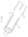
- FIG. 11 is an isometric view from diagonally below of the engagement of thescreen 102 and the frame rails 200.
- the screen 102 has bars or ribs (called flights) 210 attached to the screen.
- the bars (flights) have notches 220 sized and shaped to enable the ribs 210 of the screen 102 to slide over the rails 200.
- the bars (flights 210) are equally spaced over the screen.
- the padding machine can have two spaced-apart parallel generally L-shaped frame rails 200.
- FIG. 12 is a cross sectional front view of the engagement of the screen 102 and the frame rail 200.
- FIG. 12 shows the bar/flight 210 and its notch 220 that is adapted (i.e. sized and shaped) to provide a sliding fit over the frame rail 200b.
- the screen 102 of FIG. 12 may be a steel screen or a composite polymer-steel screen (e.g. a polyurethane-steel screen) as described above.
- FIGS. 13 and 14 are isometric and plan views of the composite polymer-steel screen 102.
- FIGS. 13 and 14 depict the construction of the screen 102.
- the screen 102 in this particular implementation has orthogonal wire-like members 132, 134 that are overlaid or interlaced to form a mesh or lattice.
- the orthogonal wire-like members are polyurethane-coated steel wires, i.e. a tubular coating of polyurethane surrounding a steel inner core to form a composite cable.
- An innovative hinge mechanism or hinge assembly 170 makes this screen robust.
- the tubular polyurethane (PU) coating 172 is stripped away or otherwise removed from the ends of the wire-like members 132, 134 to expose the steel inner core 174.
- a steel cable fitting or cylindrical head 176 is crimped onto the exposed steel inner core to act as a stopper.
- Two small strips 180 of mild steel (or equivalent) are laid down beside the cable to act as a gripping surface.
- Strips of polyurethane 182 are placed on the outer surfaces of the metal strips 180 as shown in FIG. 13 .
- the strips of polyurethane 182 also extend over and under a portion 184 of the polyurethane tubular coating.
- a cover piece 186 of mild steel (or equivalent) is folded or bent to form a U-shaped hinge 188.
- the cover piece 186 clasps or "sandwiches” together the various strips 180, 182.
- the hinge assembly is screwed, riveted, or welded through both the PU and mild steel strips.
- a plurality of fasteners, rivets, or welds 190 are used in the illustrated embodiment to secure the various strips of the hinge mechanism. This layered construction creates an extremely tight grip on both the inner steel core of the screen and the PU coating which provides a stable and robust hinge for long-term use.
- FIG. 15 depicts e.g. lower pulley teeth which are sized and shaped to engage the screen.
- the e.g. lower pulley 300 has rows 305 of teeth 310.
- each row 305 has five teeth 310.
- the number of teeth may be varied in order to accommodate different screen designs (different mesh size).
- the teeth are all of the same shape and size although this may be varied in other embodiments.
- the teeth in each row are equally spaced apart from each other. This may be varied in other embodiments.
- FIG. 16 depicts e.g. lower pulley bars.
- the lower pulley 300 has pulley bars 320.
- the pulley bars 320 engage the corresponding screen-mounted bars or ribs 210 on the underside of the screen 102, providing transmission of torque while optionally also allowing for some slippage in situations where the material is hard to work with and where transmitting the full torque to a stalled screen may cause damage.
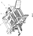
- FIG. 17 depicts a modified padding machine 300 having mounting hooks 310, 320.
- the mounting hooks are supported by traverse members 330 of the frame.
- the mounting hooks 310, 320 are parallel and spaced apart.
- the mounting hooks 310, 320 enable the padding machine to be hung from a stick of an excavator.
- the frame is designed to hang the padding machine from directly its center of gravity.
Landscapes
- Engineering & Computer Science (AREA)
- Mining & Mineral Resources (AREA)
- Civil Engineering (AREA)
- General Engineering & Computer Science (AREA)
- Structural Engineering (AREA)
- Mechanical Engineering (AREA)
- Excavating Of Shafts Or Tunnels (AREA)
- Belt Conveyors (AREA)
Description
- The present disclosure relates generally to earthmoving machines and apparatus. More particularly, the present disclosure is related to padding machines.
- Underground cables and pipelines are typically emplaced by laying the cable or pipeline in a prepared trench and subsequently backfilling the trench.
- Some cables and pipelines are susceptible to damage from stones or other hard objects in the backfill material. For example, optical fiber communications cables are considered particularly susceptible to damage in this manner, as are polymeric or plastic pipelines. Also, steel pipes are increasingly provided with protective polymeric coatings, which must be protected from penetration or damage by hard objects.
- Consequently, in the laying of cables and pipelines it is increasingly sought to backfill the trench with fill material that is relatively free of stones or other hard objects. One way to achieve this is to backfill the trench with sand or other suitable fill material brought from a remote source of sand or rock-free soil. This approach is however relatively expensive and time-consuming. Further, where steel pipe is covered with a layer of sand, the filled trench tends to collect standing water in the porous sand fill, leading to premature corrosion of the pipe. Also, the use of a fill material that is different from the surrounding soil results in a loss of cathodic protection, which also leads to premature corrosion of steel pipe. The alternative is to screen the soil dug from the trench, to remove stones and other foreign objects, and return the screened soil to the trench. Several machines, known as padding machines, have been disclosed in the prior art for this purpose.
- For example,
U.S. Pat. No. 2,857,691 to Curran discloses a tracked vehicle having a vertically swingable boom that extends laterally over a trench. The boom includes a tube having an enclosed auger. At the far end of the boom from the vehicle is a rotating head which scoops up soil from alongside the trench, screens the soil, and transmits it to the auger, which conveys the screened soil along the tube and into the trench through openings in the tube. The Curran apparatus is particularly designed for use with a vehicle that is driven along the opposite side of a trench from the pile of soil that was removed from the trench and which extends alongside the trench. -
U.S. Pat. No. 4,633,602, to Layh, et al. , teaches the use of a gathering belt which dumps material onto a separator screen, allowing fines to fall onto a lateral belt. This device does not provide for screening during the initial conveying nor for attachment to vehicles, such as loaders and bulldozers. -
U.S. Pat. No. 3,596,384 to Neujahr employs an auger to remove soil from the piled ridge of soil removed from a trench to a second auger, which conveys the soil to a screen and to a set of impellers which throw the screened soil into the trench. -
U.S. Pat. No. 4,301,910 to Price also discloses a self-propelled backfilling machine which utilizes a conveyor belt to transport soil from a hopper into a trench. -
U.S. Pat. No. 4,664,791, issued May 12, 1987 to McClain et al. , also discloses a padding machine particularly designed to receive backfill material in a hopper and to sieve the material and dispense it into a trench.US5540003A1 discloses a padding machine according to the preamble ofclaim 1. - The aforementioned padding machines are generally large machines intended and useful primarily for long-distance pipe laying operations in open country, where rights of way are wide and where there is little or no rugged terrain. Such machines have limited usefulness where rights of way are narrow, where trenches do not follow a straight path, or where the terrain is relatively rugged.
-
U.S. Pat. No. 5,479,726 discloses a compact padding machine and padding machine attachment for a vehicle. When padding of a ditch for a pipeline or cable is required, the padding machine is removably attached in a position at one end of a conventional bucket loader, bulldozer, or other base machine or vehicle, whereby said attachment moves along the path of travel of the vehicle. As the vehicle moves the padding machine attachment along one side of the pipeline ditch, the padding machine attachment picks up at least a portion of a pile of excavated material placed parallel to and along the same side of the ditch and processes the excavated material into padding material for placement into the ditch for padding the pipeline or cable. - Although the prior technologies are adequate for some applications, further improvements to the padding machine are desired particularly in order to improve productivity. Accordingly, an improved padding machine would be highly desirable.
- The following presents a simplified summary of some aspects or embodiments of the invention in order to provide a basic understanding of the invention. This summary is not an extensive overview of the invention. It is not intended to identify key or critical elements of the invention or to delineate the scope of the invention. Its sole purpose is to present some embodiments of the invention in a simplified form as a prelude to the more detailed description that is presented later.
- The present specification discloses padding machine having larger aperture steel and polyurethane-coating steel screens which are support by flight rails.
- One inventive aspect of the disclosure is a padding machine according to
claim 1. The improved design results in a more efficient and productive padding machine. - Other inventive aspects of the disclosure may become apparent to the persons skilled in the art.
- These and other features of the disclosure will become more apparent from the description in which reference is made to the following appended drawings.
- The accompanying drawings, which are incorporated into and form a part of the specification, illustrate several embodiments of the present invention and, together with the description, serve to explain the principles of the invention. The drawings are only for the purpose of illustrating a preferred embodiment of the invention and are not to be construed as limiting the invention.
-
FIG. 1 is an isometric view of a prior-art padding machine, shown attached to a loader and being used to partially backfill a trench containing a pipeline or cable. -
FIG. 2 is a cut away isometric view of the padding machine shown inFIG. 1 . -
FIG. 3 is a side view in cross section of the padding machine ofFIG. 1 . -
FIG. 4 is a front view of the padding machine ofFIG. 1 , with the conveyor belt shifted to the opposite side; -
FIG. 5 is an isometric view of the padding machine ofFIG. 1 . -
FIG. 6 is an isometric rear view of the padding machine ofFIG. 1 , shown attachable to a bucket of a loader or bulldozer. -
FIG. 7 is an isometric view of a padding machine attached to a tracked vehicle in accordance with an embodiment of the present invention. -
FIG. 8 is an isometric view of a padding machine having an elevator belt. -
FIG. 9 is an isometric view of a padding machine having an elevator plate. -
FIG. 10 is an isometric view of a padding machine having frame rails. -
FIG. 11 is an isometric view of the engagement of the screen and rails. -
FIG. 12 is a front view of the engagement of the screen and rails. -
FIG. 13 is an isometric view of the composite polymer-steel screen. -
FIG. 14 is a plan view of the composite polymer-steel screen. -
FIG. 15 depicts the lower pulley teeth. -
FIG. 16 depicts the lower pulley bars. -
FIG. 17 is an isometric view of a padding machine having mounting hooks in accordance with another embodiment of the present invention. - The following detailed description contains, for the purposes of explanation, numerous specific embodiments, implementations, examples and details in order to provide a thorough understanding of the invention. It is apparent, however, that the embodiments may be practiced without these specific details or with an equivalent arrangement. In other instances, some well-known structures and devices are shown in block diagram form in order to avoid unnecessarily obscuring the embodiments of the invention. The description should in no way be limited to the illustrative implementations, drawings, and techniques illustrated below, including the exemplary designs and implementations illustrated and described herein, but may be modified within the scope of the appended claims along with their full scope of equivalents.
- Illustrated in
FIGS. 1 to 6 is a paddingmachine 20 according to the prior art. The paddingmachine 20 includes anangular frame 22 which includes a pair of triangularside frame members side frame members bottom frame members 28 or a solid plate, or a rear cross plate, and can include optional reinforcing members, cross bars, orsafety bars machine 20 includes alip 36 which spans and connects theside frame members machine 20, and which is positioned to be located at ground level and to function as a cutting blade when themachine 20 is in operation. Theside frame members disposed wings machine 20. - The padding
machine 20 further includes aninclined conveyor belt 42 and aninclined screening belt 44. Theconveyor belt 42 is a reinforced elastomeric belt, of the type customarily used in conveyor applications. Thescreening belt 44 is a chain link belt, e.g. having a chain link spacing size on the order of approximately one-half to one inch. Thescreening belt 44 may have a number of raised cross bars 45 on its outer surface, which function to assist in scooping earth onto thescreening belt 44. - The
conveyor belt 42 travels on alower roller 46 and anupper roller 48, which are journaled in associated bearings mounted in theside frame members screening belt 44 also travels on thelower roller 46, and rides on top of theconveyor belt 42. Additionally, the screening belt travels over anupper drive roller 50 which is located at the top and rear of theframe 22, anidler roller 52 located beneath and slightly forward of thedrive roller 50, and alower roller 54 located at the rear lower corner of theframe 22. Therollers side frame members - The
drive roller 50 is driven by ahydraulic motor 56 which is mounted on theside frame member 24. Thehydraulic motor 56 is connected to thedrive roller 50 by adrive chain 58 and associated sprockets. Thehydraulic motor 56 may be connected by means ofhydraulic hoses 60 to a conventional auxiliary hydraulic power output, for example a hydraulic power output of aloader 62 as shown inFIG. 1 . - The
motor 56 drives thescreening belt 44 by means of thedrive roller 50. Thescreening belt 44 in turn drives theconveyor belt 42 as a consequence of traveling over the conveyor belt onroller 46. As a result, theconveyor belt 42 and thescreening belt 44 travel at the same speed. - Several tapered
polymeric spacers 64 are positioned between the screeningbelt 44 and theconveyor belt 42, near the upper end of theconveyor belt 42. Thespacers 64 operate to cause thescreening belt 44 to separate from theconveyor belt 42 as thescreening belt 44 andconveyor belt 42 travel upwardly from the lower roller. - A hydraulically driven
vibrator 66 is mounted beneath thescreening belt 44 at a position just beyond theroller 48. Thevibrator 66 is positioned to shake thescreening belt 44 as it passes beyond the end of theconveyor belt 42. - The padding
machine 20 further includes a transversedischarge conveyor belt 68, which extends transversely with respect to the longitudinal axis and the direction of travel of the paddingmachine 20. Thedischarge conveyor belt 68 is positioned directly beneath the upper end of theinclined conveyor belt 42, so as to receive soil carried upwardly on theconveyor belt 42 and discharged overroller 48. Thedischarge conveyor belt 68 extends outwardly through an opening in theside frame member 24, and extends up to several feet from theframe 22 to as to enable fine-grained soil to be conveyed into a nearby trench. - The
discharge conveyor belt 68 travels onrollers 70 which are journaled to anelongate conveyor frame 72. A reversible hydraulic motor, mounted within theelongate conveyor frame 72, drives thedischarge belt 68. Theconveyor frame 72 rests on transverse support rails 76. Theconveyor frame 72 and thedischarge belt 68 may be slid in either direction on the support rails 76, so as to be extendible from either side of the paddingmachine 20. This arrangement enables screened soil to be discharged into a trench on either side of the paddingmachine 20. - The rear ends of the padding machine
side frame members arms 63 of aconventional loader 62, Theside frame members 24 and 25 also includehooks 82, by which the padding machine can be engaged and supported by abucket 65 of a loader or bulldozer, as shown for example inFIGS. 1 and6 . One ofmore hooks 82 are adapted to receive aconventional bucket 65. - In operation, the padding machine is attached to the front end of a loader, such as a bulldozer or
loader 62 shown inFIG. 1 , or the bucket, as shown inFIGS. 1 and6 . The padding machine is powered by the auxiliary hydraulic output of theloader 62. The paddingmachine 20 is positioned with thelip 36 at ground level, and is normally driven along the ridge of earth, or berm, that is formed adjacent a trench by conventional trench digging equipment. Thelip 36 and thewings screening belt 44. - As the earth is carried up the
screening belt 44, fine grained soil passes through thescreening belt 44 and onto theinclined conveyor belt 42, from where it is discharged onto thetransverse discharge belt 68 and conveyed into the nearby trench. Rocks are carried to the top of thescreening belt 44 and are discharged onto the ground behind the padding machine. Alternatively, rocks may be collected in a bucket behind the padding machine, or they may be conveyed to one side or the other by the auxiliary device described below, or they may be carried towards a bar to force rock to either side and down a chute (not shown). - The
vibrator 66 serves to break up clods of fine-grained soil and thereby facilitate its passage through thescreening belt 44. Thevibrator 66 is particularly useful where soil is damp or wet. - Illustrated in
FIGS. 7-16 are two embodiments of the present invention. In a first embodiment, the padding machine includes a large-aperture metal, e.g. steel screen. In a second embodiment, the padding machine includes a polymer/steel composite screen. These two different screens both provide larger apertures for the padding machine compared to the prior version of the padding machine, thereby significantly improving the padding machine's productivity. As depicted byfigures 11 and12 the screening belt according to the invention comprises further ribs (210) attached to the screen, wherein each rib (210) has a notch (220) adapted to partially and slidably receive the respective frame rail (200). - The forward facing surface of the padding machine has an elevator which includes a metal, e.g. steel elevator chain (also referred to as the screen 102) that acts like a perforated conveyor belt to pick up material from the ground and allow the fine components ("fines") to fall through the apertures of the
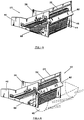
screen 102 while forcing the oversize material to go over the top of the machine and to be deposited back on the ground. The fines drop onto anelevator belt 104 which is a conventional rubber conveyor belt disposed beneath theelevator chain 102, which dumps the fines onto the conveyor orconveyor belt 104. Theconveyor belt 104, in the illustrated embodiments, can be a standard rubber belt which may be adjustable from side to side for the purpose of depositing the fines into a ditch as the machine runs alongside the ditch. Theelevator chain 102 runs onmultiple pulleys 300, preferably three pulleys (although additional pulleys may be provided in variants). Thepulleys 300 apply tension to drive the screening belt by the force of friction. Theelevator chain 102 is guided into the center of those pulleys by collars which act upon the edges of theelevator chain 102. - In the first embodiment, the
elevator chain 102 that is made of out of steel has larger-than-normal apertures to allow more material to fall through, thus allowing greater productivity. This requires the use of relatively small wire in producing the screen due to manufacturing constraints. As a result, this screen may be too fragile and the forces imparted by theelevator chain 102 being pulled from one side or the other during work may destroy the screening belt due to the heavy interaction between the edges of elevator chain and the collars which guide the screen from side to side. As a result, the edges or the collars could be destroyed.. - Frame rails 200 are therefore provided to support the
screen 102. Two or more metal,e.g. steel rails 200 are mounted on the frame (the frame comprises e.g.side frame members ribs 210 extending transversely to the running direction of theelevator chain 102. Thebars 210 are also called flights. Theflights 210 comprisenotches 220 cut into theflights 210 which are part of theelevator chain 102. Theflights 210 may be used to help clear large rocks off the screen. Thenotches 220 may allow theflights 210 to ride on the flight rails (i.e. frame rails 200) and to force the screen to remain centered while imparting the forces on the strong center of theelevator chain 102 instead of on the more fragile edges. This solution is effective in preventing the elevator chain from wearing out during use. - In the second embodiment, the screen is a composite polymer-steel screen. In one specific implementation, the screen is a polyurethane screen with a steel inlay. The figures depict the construction of the screen and its hinge mechanism (
figs. 13 and14 ). This polymer material was found to be quite tough, but extremely stretchy and vulnerable to being pinched and damaged at certain points in the machine. The screen's relatively soft polymer made it difficult to drive and it was also found that the flight rails 210 as described above were inadequate for driving or guiding this type of screen. Upon further development, innovative technical solutions were devised to both these problems. For driving thescreen 102, one of thepulleys 300 hasteeth 310. The teeth are similar to sprocket teeth. Theteeth 310 are preferably designed with a cross section to avoid overgripping the material. Theteeth 310 on thepulley 300 transmit the torque of the driving motor(s) to keep thescreen 102 centered. To prevent thescreen 102 from being pinched and thus damaged, theelevator belt 104 may be removed from underneath the elevator chain, and may be replaced with a hard plate (as shown in figures). Although this solution was developed for the composite polymer-steel screen (the second embodiment), it works equally well for the steel screen (the first embodiment). This design reduces pinch points and thus damage to the screen. Both of these improvements result in significant increases to the screen lifetime and performance. It will be appreciated that the shape of the sprocket teeth may be varied from what is shown in the figures. It has to be noted that both embodiments may be combined in usage of both, the flights guided by the flight rails of the first embodiment and the teeth on the pulley of the second embodiment. -
FIG. 7 is an isometric view of apadding machine 100 attached to a trackedvehicle 200. The trackedvehicle 200 has acab 210,tracks 220,front attachment mechanism 230 to detachably mount thepadding machine 100, and one ormore actuators 240 to move the front attachment mechanism and padding machine. The trackedvehicle 200 is merely an example of one type of vehicle for the purposes of illustration. The padding machine may be mounted to any other suitable type of vehicle. Thepadding machine 100 is designed for moving along a side of a ditch, scooping up excavated material from the side of the ditch, and sifting the excavated material into padding material for filling in the ditch. As will be described in further detail below, the padding machine has a frame comprisingside frame members frame rails 200 spaced apart from theside frame members screening belt 102 driven around pulleys 300 supported by the frame, e.g. theside frame members screening belt 102 comprising a screen for collecting and conveying the excavated material upwardly. The screen comprises apertures for sifting the excavated material into padding material by permitting the padding material to fall through the apertures of the screen. The screen runs over the frame rails 200 which support the screen. - As illustrated by way of example in
FIG. 7 , thepadding machine 100 includes a screening belt 102 (also referred to herein as a screen or conveyor belt). Thepadding machine 100 further includes a transverse discharge conveyor orconveyer belt 104, which extends transversely with respect to the longitudinal axis and the direction of travel of the padding machine. Thedischarge conveyor 104 is positioned beneath the upper end of theinclined screening belt 102, so as to receive soil carried upwardly on the screening belt. Thedischarge conveyor belt 104 extends outwardly through an opening in the side frame member, and extends up to several feet from the frame to as to enable fine-grained soil to be conveyed into a nearby trench. Thedischarge conveyor belt 104 is mounted to the frame beneath anupper run 103 of thescreening belt 102 wherein thedischarge conveyor belt 104 receives the padding material passing through thescreen and discharges the padding material into the ditch. -
FIG. 8 is an isometric view of apadding machine 100 having anelevator belt 110. Theelevator belt 110 can be identical to thescreening belt 102. The padding machine hasside frame members disposed wings side frame members bottom frame member 128 and a solidrear cross plate 130. The frame can include optional reinforcing members, cross bars, or safety bars. -
FIG. 9 is an isometric view of apadding machine 100 having anelevator plate 150. The plate may be a flat plate made of steel or polymer over which thescreen 102 is drawn so as to pull the material over the opening. This plate provides almost the same effectiveness of the belt but at a much lower cost and complexity. The padding machine can be modified or adapted for different soil conditions or jobs by switching between the plate and belt. The plate is good for general purpose use but if in extreme conditions it is best to revert back to the belt for its slightly better performance. A padding machine capable of swapping between these systems represents a substantial improvement in the art -
FIG. 10 is an isometric view of apadding machine 100 having frame rails 200. The frame rails 200 are parallel and spaced-apart from each other and are likewise parallel and spaced-apart from theside frame members -
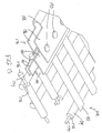
FIG. 11 is an isometric view from diagonally below of the engagement ofthescreen 102 and the frame rails 200. Thescreen 102 has bars or ribs (called flights) 210 attached to the screen. The bars (flights) havenotches 220 sized and shaped to enable theribs 210 of thescreen 102 to slide over therails 200. Thus, the upper edges of frame rails are received in thenotches 220 which results in a lateral guidance of theribs 210 and thus thescreen 102 by the frame rails 200. In the embodiment shown inFIG. 11 , the bars (flights 210) are equally spaced over the screen. As shown in the illustrated embodiment ofFIG. 11 , the padding machine can have two spaced-apart parallel generally L-shaped frame rails 200. -
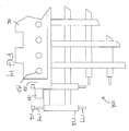
FIG. 12 is a cross sectional front view of the engagement of thescreen 102 and theframe rail 200.FIG. 12 shows the bar/flight 210 and itsnotch 220 that is adapted (i.e. sized and shaped) to provide a sliding fit over the frame rail 200b. Thescreen 102 ofFIG. 12 may be a steel screen or a composite polymer-steel screen (e.g. a polyurethane-steel screen) as described above. -
FIGS. 13 and14 are isometric and plan views of the composite polymer-steel screen 102.FIGS. 13 and14 depict the construction of thescreen 102. As shown inFIGS. 13 and14 , thescreen 102 in this particular implementation has orthogonal wire-like members 132, 134 that are overlaid or interlaced to form a mesh or lattice. In this embodiment, the orthogonal wire-like members are polyurethane-coated steel wires, i.e. a tubular coating of polyurethane surrounding a steel inner core to form a composite cable. An innovative hinge mechanism or hinge assembly 170 makes this screen robust. To manufacture the hinge mechanism 170, the tubular polyurethane (PU) coating 172 is stripped away or otherwise removed from the ends of the wire-like members 132, 134 to expose the steelinner core 174. A steel cable fitting orcylindrical head 176 is crimped onto the exposed steel inner core to act as a stopper. Twosmall strips 180 of mild steel (or equivalent) are laid down beside the cable to act as a gripping surface. Strips ofpolyurethane 182 are placed on the outer surfaces of the metal strips 180 as shown inFIG. 13 . The strips ofpolyurethane 182 also extend over and under aportion 184 of the polyurethane tubular coating. Thestrips 182 thus grip both the exposed steel cores and the tubular PU coating so that, under stress, the steel wire cannot pull out of the rest of the PU coating. Acover piece 186 of mild steel (or equivalent) is folded or bent to form aU-shaped hinge 188. Thecover piece 186 clasps or "sandwiches" together thevarious strips -
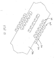
FIG. 15 depicts e.g. lower pulley teeth which are sized and shaped to engage the screen. As depicted inFIG. 15 , the e.g.lower pulley 300 hasrows 305 ofteeth 310. In this specific implementation, eachrow 305 has fiveteeth 310. It will be appreciated that in other variants the number of teeth may be varied in order to accommodate different screen designs (different mesh size). In this illustrated embodiment, the teeth are all of the same shape and size although this may be varied in other embodiments. In this illustrated embodiment, the teeth in each row are equally spaced apart from each other. This may be varied in other embodiments. -
FIG. 16 depicts e.g. lower pulley bars. As depicted, thelower pulley 300 has pulley bars 320. The pulley bars 320 engage the corresponding screen-mounted bars orribs 210 on the underside of thescreen 102, providing transmission of torque while optionally also allowing for some slippage in situations where the material is hard to work with and where transmitting the full torque to a stalled screen may cause damage. -
FIG. 17 depicts a modifiedpadding machine 300 having mountinghooks traverse members 330 of the frame. The mounting hooks 310, 320 are parallel and spaced apart. The mounting hooks 310, 320 enable the padding machine to be hung from a stick of an excavator. The frame is designed to hang the padding machine from directly its center of gravity. - It is to be understood that the singular forms "a", "an" and "the" include plural referents unless the context clearly dictates otherwise. Thus, for example, reference to "a device" includes reference to one or more of such devices, i.e. that there is at least one device. The terms "comprising", "having", "including", "entailing" and "containing", or verb tense variants thereof, are to be construed as open-ended terms (i.e., meaning "including, but not limited to,") unless otherwise noted. All methods described herein can be performed in any suitable order unless otherwise indicated herein or otherwise clearly contradicted by context. The use of examples or exemplary language (e.g. "such as") is intended merely to better illustrate or describe embodiments of the invention and is not intended to limit the scope of the invention unless otherwise claimed.
- While several embodiments have been provided in the present disclosure, it should be understood that the disclosed systems and methods might be embodied in many other specific forms without departing from the scope of the present disclosure.
Claims (8)
- A padding machine (100) for moving along a side of a ditch, scooping up excavated material from the side of the ditch, and sifting the excavated material into padding material for filling in the ditch, the machine comprising:a frame comprising side frame members (124; 126) and frame rails (200) spaced apart from the side frame members (124; 126); anda screening belt (102) and pulleys (300) supported by the frame, the screening belt (102) being driven around the pulleys (300), the screening belt (102) comprising a screening belt for collecting and conveying the excavated material upwardly, wherein the screening belt comprises apertures for sifting the excavated material into padding material by permitting the padding material to fall through the apertures of the screen, wherein the screening belt runs over the frame rails (200) which support the screen; anda discharge conveyor (104) mounted to the frame beneath an upper run of the screening belt wherein the discharge conveyor (104) is adapted for receiving the padding material passing through the screening belt and for discharging the padding material into the ditch,characterized in that the screening belt comprises ribs (210) attached to the screen, wherein each rib (210) has a notch (220) adapted to partially and slidably receive the respective frame rail (200).
- The padding machine of claim 1, the frame rails (200) comprising two spaced-apart L-shaped frame rails (200) parallel oriented with respect to each other.
- The padding machine of any of the previous claims, wherein the screening belt is comprised of polyurethane-coated steel.
- The padding machine of any of the previous claims, wherein at least one of the pulleys (300) comprises teeth (310) sized and shaped to grip the screen, wherein at least one of the pulleys (300) comprises bars (320) sized and shaped to engage the ribs (210) of the screening belt.
- The padding machine of any of the previous claims, wherein the screening belt includes a hinge assembly that comprises polyurethane (182) and metal strips (180) secured between a U-shaped cover piece (186), wherein a tubular polyurethane coating (172) is stripped away from ends of wire-like members of the screening belt to expose a steel inner core (174), wherein a steel cable fitting (176) is crimped onto the exposed steel inner core (174) to act as a stopper, wherein two strips of the metal strips (180) are laid down onto the exposed steel inner core (174) in between the steel cable fitting (176) and the tubular polyurethane coating (172) to act as a gripping surface and wherein the strips of polyurethane (182) are placed on the outer surfaces of the laid down metal strips (180).
- The padding machine of claim 5 wherein the strips of polyurethane (182) also extend over and under a portion of the polyurethane tubular coating (172) such that the strips of polyurethane (182) cover both the exposed steel inner core (174) and the tubular polyurethane coating (172).
- The padding machine of claim 5 or 6, wherein the cover piece (186) is secured to the metal (180) and the polyurethane strips (182) by screws, rivets, or welds (190).
- The padding machine of any of the previous claims, further comprising a front attachment mechanism (230) for detachably mounting to a tracked vehicle.
Applications Claiming Priority (1)
| Application Number | Priority Date | Filing Date | Title |
|---|---|---|---|
| CA3028280A CA3028280C (en) | 2018-12-21 | 2018-12-21 | Padding machine |
Publications (3)
| Publication Number | Publication Date |
|---|---|
| EP3670760A2 EP3670760A2 (en) | 2020-06-24 |
| EP3670760A3 EP3670760A3 (en) | 2020-08-19 |
| EP3670760B1 true EP3670760B1 (en) | 2021-11-24 |
Family
ID=66105148
Family Applications (1)
| Application Number | Title | Priority Date | Filing Date |
|---|---|---|---|
| EP19168572.6A Active EP3670760B1 (en) | 2018-12-21 | 2019-04-11 | Padding machine |
Country Status (4)
| Country | Link |
|---|---|
| US (1) | US11421398B2 (en) |
| EP (1) | EP3670760B1 (en) |
| AU (1) | AU2019200523B2 (en) |
| CA (1) | CA3028280C (en) |
Families Citing this family (4)
| Publication number | Priority date | Publication date | Assignee | Title |
|---|---|---|---|---|
| USD943009S1 (en) * | 2019-11-06 | 2022-02-08 | Albert Ben Currey | Bucket |
| US11446703B2 (en) | 2019-11-06 | 2022-09-20 | Albert Ben Currey | Bucket with vibrating screen |
| DE102022112640B3 (en) | 2022-05-19 | 2023-03-16 | Kleemann Gmbh | processing plant |
| CN116240940A (en) * | 2023-03-22 | 2023-06-09 | 中国南方电网有限责任公司超高压输电公司广州局 | A submarine cable riprap dam deprotection and cleaning equipment |
Family Cites Families (27)
| Publication number | Priority date | Publication date | Assignee | Title |
|---|---|---|---|---|
| US2255581A (en) * | 1940-01-26 | 1941-09-09 | Borg Warner | Screen frame wedge retainer assembly |
| US2857691A (en) | 1956-02-13 | 1958-10-28 | M J Crose Mfg Company Inc | Pipeline ditch filling and pipe padding machine |
| US3596384A (en) | 1968-12-09 | 1971-08-03 | Roy E Neujahr | Excavation refill packer |
| DE7505976U (en) | 1975-02-26 | 1978-06-01 | Passavant-Werke Michelbacher Huette, 6209 Aarbergen | BELT SCREEN |
| GB1558086A (en) | 1976-11-10 | 1979-12-19 | Spiller C M | Screening |
| US4301910A (en) | 1979-08-30 | 1981-11-24 | Kros Konveyors, Inc. | Self-propelled receptacle-conveyor backfilling apparatus |
| US4377365A (en) | 1980-10-27 | 1983-03-22 | Layh Ricky L | Pipeline padding machine and method |
| US4633602A (en) | 1985-09-03 | 1987-01-06 | Layh Ricky L | Method and apparatus for padding pipe |
| US4664791A (en) | 1986-02-07 | 1987-05-12 | Mcclain Ray | Padding machines |
| FI872331L (en) | 1986-05-27 | 1987-11-28 | Anglo Amer Corp South Africa | ANORDNING OCH FOERFARANDE FOER SEPARERING AV EN FAST KOMPONENT FRAON EN ANNAN FAST KOMPONENT I SUSPENSION I EN VAETSKA. |
| US5195260A (en) | 1988-10-11 | 1993-03-23 | Mark Osadchuk | Pipeline padding apparatus |
| US5120433A (en) | 1988-10-11 | 1992-06-09 | Ozzie's Pipeline Padder, Inc. | Pipeline padding apparatus |
| US5430962A (en) | 1988-10-11 | 1995-07-11 | Ozzie's Pipeline Padder, Inc. | Pipeline padding apparatus with rotary feeder |
| US5363574A (en) | 1988-10-11 | 1994-11-15 | Mark Osadchuk | Pipeline padding apparatus |
| US4912862A (en) | 1989-01-09 | 1990-04-03 | Bishop William B | Backfill machine |
| US5261171A (en) | 1990-03-26 | 1993-11-16 | Bishop William B | Pipeline padding machine attachment for a vehicle |
| US5097610A (en) * | 1990-03-26 | 1992-03-24 | Bo-Ar Padding Co., Inc. | Compact padding machine |
| DE4118022C2 (en) | 1991-06-01 | 2000-01-20 | Hans J Altmeyer | Vibrating fine sieve |
| GB9126185D0 (en) | 1991-12-10 | 1992-02-12 | Woodburn William | Apparatus for filtering cuttings from drilling fluid |
| US5375721A (en) | 1992-04-23 | 1994-12-27 | Lavigne; Gordon | Apparatus for dry placer mining |
| DE4445515C2 (en) | 1993-12-21 | 1997-02-13 | Nilos Gmbh | Screening device |
| US5540003A (en) * | 1994-07-22 | 1996-07-30 | Osadchuk; Mark | Padding machine with shaker for separator |
| US5741087A (en) | 1996-08-05 | 1998-04-21 | Osadchuk; Mark | Chain separator for padding machine |
| US6024228A (en) | 1997-10-09 | 2000-02-15 | Tuboscope Nu-Tec/Gnt | Bypass diverter box for drilling mud separation unit |
| US6910587B2 (en) | 2002-08-02 | 2005-06-28 | Varco I/P, Inc. | Gumbo separator methods and apparatuses |
| US20080092410A1 (en) | 2006-10-19 | 2008-04-24 | Layh Ricky L | Pipeline padding machine |
| KR20130046593A (en) | 2011-10-28 | 2013-05-08 | 현대제철 주식회사 | Screen apparatus for selecting coke |
-
2018
- 2018-12-21 CA CA3028280A patent/CA3028280C/en active Active
-
2019
- 2019-01-25 AU AU2019200523A patent/AU2019200523B2/en active Active
- 2019-04-02 US US16/373,188 patent/US11421398B2/en active Active
- 2019-04-11 EP EP19168572.6A patent/EP3670760B1/en active Active
Also Published As
| Publication number | Publication date |
|---|---|
| AU2019200523A1 (en) | 2020-07-09 |
| US20200199846A1 (en) | 2020-06-25 |
| CA3028280A1 (en) | 2020-06-21 |
| EP3670760A3 (en) | 2020-08-19 |
| AU2019200523B2 (en) | 2024-10-10 |
| US11421398B2 (en) | 2022-08-23 |
| EP3670760A2 (en) | 2020-06-24 |
| CA3028280C (en) | 2020-10-20 |
Similar Documents
| Publication | Publication Date | Title |
|---|---|---|
| US5261171A (en) | Pipeline padding machine attachment for a vehicle | |
| US5097610A (en) | Compact padding machine | |
| US11421398B2 (en) | Padding machine | |
| US3701422A (en) | Vehicle mounted earth separating and conveying system | |
| US5421108A (en) | High volume pipe padding machine | |
| AU2002302058A1 (en) | Excavator Sizing Bucket | |
| US5741087A (en) | Chain separator for padding machine | |
| US5540003A (en) | Padding machine with shaker for separator | |
| US4616880A (en) | Continuous excavating machine | |
| US6055749A (en) | Apparatus for padding underground conduits | |
| US20080092411A1 (en) | Compact padding attachments | |
| US6138837A (en) | Combination screen/conveyor device removably attachable to a vehicle | |
| US10940507B2 (en) | Mobile material sifter | |
| US4731941A (en) | Dragline hoe, method and apparatus | |
| CA2329045C (en) | Method and pulverizer for pipeline trench padding | |
| JPH09316920A (en) | Ditching device, ditching method, and groove backfilling method | |
| JPH1037237A (en) | Groove backfilling device, groove backfilling method, and groove backfilling device with groove digging device | |
| US6029378A (en) | Apparatus for padding underground conduits | |
| US5465511A (en) | Trenching machine | |
| JPH09316919A (en) | Ditching device and ditching method | |
| CA1288735C (en) | Dragline apparatus | |
| RU2077637C1 (en) | Method for opencast mining and bulldozer equipment | |
| US4048734A (en) | Ditch digging apparatus | |
| WO2016074006A1 (en) | A soil displacement apparatus | |
| JPS5841382B2 (en) | Trencher earth removal equipment |
Legal Events
| Date | Code | Title | Description |
|---|---|---|---|
| PUAI | Public reference made under article 153(3) epc to a published international application that has entered the european phase |
Free format text: ORIGINAL CODE: 0009012 |
|
| STAA | Information on the status of an ep patent application or granted ep patent |
Free format text: STATUS: THE APPLICATION HAS BEEN PUBLISHED |
|
| AK | Designated contracting states |
Kind code of ref document: A2 Designated state(s): AL AT BE BG CH CY CZ DE DK EE ES FI FR GB GR HR HU IE IS IT LI LT LU LV MC MK MT NL NO PL PT RO RS SE SI SK SM TR |
|
| AX | Request for extension of the european patent |
Extension state: BA ME |
|
| PUAL | Search report despatched |
Free format text: ORIGINAL CODE: 0009013 |
|
| RIN1 | Information on inventor provided before grant (corrected) |
Inventor name: OWENS, LARRY Inventor name: ARGUE, CHRIS Inventor name: JAKUS, DAVID Inventor name: GRYWUL, REECE Inventor name: WALZ, MATTHEW Inventor name: DUNSTAN, ROBERT Inventor name: KHALER, ROB |
|
| RAP1 | Party data changed (applicant data changed or rights of an application transferred) |
Owner name: ESI PIPELINE SERVICES, INC. |
|
| AK | Designated contracting states |
Kind code of ref document: A3 Designated state(s): AL AT BE BG CH CY CZ DE DK EE ES FI FR GB GR HR HU IE IS IT LI LT LU LV MC MK MT NL NO PL PT RO RS SE SI SK SM TR |
|
| AX | Request for extension of the european patent |
Extension state: BA ME |
|
| RIC1 | Information provided on ipc code assigned before grant |
Ipc: E02F 5/22 20060101AFI20200713BHEP Ipc: E02F 7/06 20060101ALI20200713BHEP |
|
| STAA | Information on the status of an ep patent application or granted ep patent |
Free format text: STATUS: REQUEST FOR EXAMINATION WAS MADE |
|
| 17P | Request for examination filed |
Effective date: 20201027 |
|
| RBV | Designated contracting states (corrected) |
Designated state(s): AL AT BE BG CH CY CZ DE DK EE ES FI FR GB GR HR HU IE IS IT LI LT LU LV MC MK MT NL NO PL PT RO RS SE SI SK SM TR |
|
| GRAP | Despatch of communication of intention to grant a patent |
Free format text: ORIGINAL CODE: EPIDOSNIGR1 |
|
| STAA | Information on the status of an ep patent application or granted ep patent |
Free format text: STATUS: GRANT OF PATENT IS INTENDED |
|
| INTG | Intention to grant announced |
Effective date: 20210914 |
|
| GRAA | (expected) grant |
Free format text: ORIGINAL CODE: 0009210 |
|
| GRAS | Grant fee paid |
Free format text: ORIGINAL CODE: EPIDOSNIGR3 |
|
| STAA | Information on the status of an ep patent application or granted ep patent |
Free format text: STATUS: THE PATENT HAS BEEN GRANTED |
|
| AK | Designated contracting states |
Kind code of ref document: B1 Designated state(s): AL AT BE BG CH CY CZ DE DK EE ES FI FR GB GR HR HU IE IS IT LI LT LU LV MC MK MT NL NO PL PT RO RS SE SI SK SM TR |
|
| REG | Reference to a national code |
Ref country code: GB Ref legal event code: FG4D |
|
| REG | Reference to a national code |
Ref country code: DE Ref legal event code: R096 Ref document number: 602019009448 Country of ref document: DE |
|
| REG | Reference to a national code |
Ref country code: AT Ref legal event code: REF Ref document number: 1449969 Country of ref document: AT Kind code of ref document: T Effective date: 20211215 |
|
| REG | Reference to a national code |
Ref country code: IE Ref legal event code: FG4D |
|
| REG | Reference to a national code |
Ref country code: LT Ref legal event code: MG9D |
|
| REG | Reference to a national code |
Ref country code: NL Ref legal event code: MP Effective date: 20211124 |
|
| REG | Reference to a national code |
Ref country code: AT Ref legal event code: MK05 Ref document number: 1449969 Country of ref document: AT Kind code of ref document: T Effective date: 20211124 |
|
| PG25 | Lapsed in a contracting state [announced via postgrant information from national office to epo] |
Ref country code: RS Free format text: LAPSE BECAUSE OF FAILURE TO SUBMIT A TRANSLATION OF THE DESCRIPTION OR TO PAY THE FEE WITHIN THE PRESCRIBED TIME-LIMIT Effective date: 20211124 Ref country code: LT Free format text: LAPSE BECAUSE OF FAILURE TO SUBMIT A TRANSLATION OF THE DESCRIPTION OR TO PAY THE FEE WITHIN THE PRESCRIBED TIME-LIMIT Effective date: 20211124 Ref country code: FI Free format text: LAPSE BECAUSE OF FAILURE TO SUBMIT A TRANSLATION OF THE DESCRIPTION OR TO PAY THE FEE WITHIN THE PRESCRIBED TIME-LIMIT Effective date: 20211124 Ref country code: BG Free format text: LAPSE BECAUSE OF FAILURE TO SUBMIT A TRANSLATION OF THE DESCRIPTION OR TO PAY THE FEE WITHIN THE PRESCRIBED TIME-LIMIT Effective date: 20220224 Ref country code: AT Free format text: LAPSE BECAUSE OF FAILURE TO SUBMIT A TRANSLATION OF THE DESCRIPTION OR TO PAY THE FEE WITHIN THE PRESCRIBED TIME-LIMIT Effective date: 20211124 |
|
| PG25 | Lapsed in a contracting state [announced via postgrant information from national office to epo] |
Ref country code: IS Free format text: LAPSE BECAUSE OF FAILURE TO SUBMIT A TRANSLATION OF THE DESCRIPTION OR TO PAY THE FEE WITHIN THE PRESCRIBED TIME-LIMIT Effective date: 20220324 Ref country code: SE Free format text: LAPSE BECAUSE OF FAILURE TO SUBMIT A TRANSLATION OF THE DESCRIPTION OR TO PAY THE FEE WITHIN THE PRESCRIBED TIME-LIMIT Effective date: 20211124 Ref country code: PT Free format text: LAPSE BECAUSE OF FAILURE TO SUBMIT A TRANSLATION OF THE DESCRIPTION OR TO PAY THE FEE WITHIN THE PRESCRIBED TIME-LIMIT Effective date: 20220324 Ref country code: PL Free format text: LAPSE BECAUSE OF FAILURE TO SUBMIT A TRANSLATION OF THE DESCRIPTION OR TO PAY THE FEE WITHIN THE PRESCRIBED TIME-LIMIT Effective date: 20211124 Ref country code: NO Free format text: LAPSE BECAUSE OF FAILURE TO SUBMIT A TRANSLATION OF THE DESCRIPTION OR TO PAY THE FEE WITHIN THE PRESCRIBED TIME-LIMIT Effective date: 20220224 Ref country code: NL Free format text: LAPSE BECAUSE OF FAILURE TO SUBMIT A TRANSLATION OF THE DESCRIPTION OR TO PAY THE FEE WITHIN THE PRESCRIBED TIME-LIMIT Effective date: 20211124 Ref country code: LV Free format text: LAPSE BECAUSE OF FAILURE TO SUBMIT A TRANSLATION OF THE DESCRIPTION OR TO PAY THE FEE WITHIN THE PRESCRIBED TIME-LIMIT Effective date: 20211124 Ref country code: HR Free format text: LAPSE BECAUSE OF FAILURE TO SUBMIT A TRANSLATION OF THE DESCRIPTION OR TO PAY THE FEE WITHIN THE PRESCRIBED TIME-LIMIT Effective date: 20211124 Ref country code: GR Free format text: LAPSE BECAUSE OF FAILURE TO SUBMIT A TRANSLATION OF THE DESCRIPTION OR TO PAY THE FEE WITHIN THE PRESCRIBED TIME-LIMIT Effective date: 20220225 Ref country code: ES Free format text: LAPSE BECAUSE OF FAILURE TO SUBMIT A TRANSLATION OF THE DESCRIPTION OR TO PAY THE FEE WITHIN THE PRESCRIBED TIME-LIMIT Effective date: 20211124 |
|
| PG25 | Lapsed in a contracting state [announced via postgrant information from national office to epo] |
Ref country code: SM Free format text: LAPSE BECAUSE OF FAILURE TO SUBMIT A TRANSLATION OF THE DESCRIPTION OR TO PAY THE FEE WITHIN THE PRESCRIBED TIME-LIMIT Effective date: 20211124 Ref country code: SK Free format text: LAPSE BECAUSE OF FAILURE TO SUBMIT A TRANSLATION OF THE DESCRIPTION OR TO PAY THE FEE WITHIN THE PRESCRIBED TIME-LIMIT Effective date: 20211124 Ref country code: RO Free format text: LAPSE BECAUSE OF FAILURE TO SUBMIT A TRANSLATION OF THE DESCRIPTION OR TO PAY THE FEE WITHIN THE PRESCRIBED TIME-LIMIT Effective date: 20211124 Ref country code: EE Free format text: LAPSE BECAUSE OF FAILURE TO SUBMIT A TRANSLATION OF THE DESCRIPTION OR TO PAY THE FEE WITHIN THE PRESCRIBED TIME-LIMIT Effective date: 20211124 Ref country code: DK Free format text: LAPSE BECAUSE OF FAILURE TO SUBMIT A TRANSLATION OF THE DESCRIPTION OR TO PAY THE FEE WITHIN THE PRESCRIBED TIME-LIMIT Effective date: 20211124 Ref country code: CZ Free format text: LAPSE BECAUSE OF FAILURE TO SUBMIT A TRANSLATION OF THE DESCRIPTION OR TO PAY THE FEE WITHIN THE PRESCRIBED TIME-LIMIT Effective date: 20211124 |
|
| REG | Reference to a national code |
Ref country code: DE Ref legal event code: R097 Ref document number: 602019009448 Country of ref document: DE |
|
| PLBE | No opposition filed within time limit |
Free format text: ORIGINAL CODE: 0009261 |
|
| STAA | Information on the status of an ep patent application or granted ep patent |
Free format text: STATUS: NO OPPOSITION FILED WITHIN TIME LIMIT |
|
| PG25 | Lapsed in a contracting state [announced via postgrant information from national office to epo] |
Ref country code: AL Free format text: LAPSE BECAUSE OF FAILURE TO SUBMIT A TRANSLATION OF THE DESCRIPTION OR TO PAY THE FEE WITHIN THE PRESCRIBED TIME-LIMIT Effective date: 20211124 |
|
| 26N | No opposition filed |
Effective date: 20220825 |
|
| PG25 | Lapsed in a contracting state [announced via postgrant information from national office to epo] |
Ref country code: SI Free format text: LAPSE BECAUSE OF FAILURE TO SUBMIT A TRANSLATION OF THE DESCRIPTION OR TO PAY THE FEE WITHIN THE PRESCRIBED TIME-LIMIT Effective date: 20211124 |
|
| REG | Reference to a national code |
Ref country code: CH Ref legal event code: PL |
|
| REG | Reference to a national code |
Ref country code: BE Ref legal event code: MM Effective date: 20220430 |
|
| PG25 | Lapsed in a contracting state [announced via postgrant information from national office to epo] |
Ref country code: MC Free format text: LAPSE BECAUSE OF FAILURE TO SUBMIT A TRANSLATION OF THE DESCRIPTION OR TO PAY THE FEE WITHIN THE PRESCRIBED TIME-LIMIT Effective date: 20211124 Ref country code: LU Free format text: LAPSE BECAUSE OF NON-PAYMENT OF DUE FEES Effective date: 20220411 Ref country code: LI Free format text: LAPSE BECAUSE OF NON-PAYMENT OF DUE FEES Effective date: 20220430 Ref country code: CH Free format text: LAPSE BECAUSE OF NON-PAYMENT OF DUE FEES Effective date: 20220430 Ref country code: FR Free format text: LAPSE BECAUSE OF NON-PAYMENT OF DUE FEES Effective date: 20220430 |
|
| PG25 | Lapsed in a contracting state [announced via postgrant information from national office to epo] |
Ref country code: BE Free format text: LAPSE BECAUSE OF NON-PAYMENT OF DUE FEES Effective date: 20220430 |
|
| PG25 | Lapsed in a contracting state [announced via postgrant information from national office to epo] |
Ref country code: IE Free format text: LAPSE BECAUSE OF NON-PAYMENT OF DUE FEES Effective date: 20220411 |
|
| GBPC | Gb: european patent ceased through non-payment of renewal fee |
Effective date: 20230411 |
|
| PG25 | Lapsed in a contracting state [announced via postgrant information from national office to epo] |
Ref country code: GB Free format text: LAPSE BECAUSE OF NON-PAYMENT OF DUE FEES Effective date: 20230411 |
|
| PG25 | Lapsed in a contracting state [announced via postgrant information from national office to epo] |
Ref country code: GB Free format text: LAPSE BECAUSE OF NON-PAYMENT OF DUE FEES Effective date: 20230411 |
|
| PG25 | Lapsed in a contracting state [announced via postgrant information from national office to epo] |
Ref country code: MK Free format text: LAPSE BECAUSE OF FAILURE TO SUBMIT A TRANSLATION OF THE DESCRIPTION OR TO PAY THE FEE WITHIN THE PRESCRIBED TIME-LIMIT Effective date: 20211124 Ref country code: CY Free format text: LAPSE BECAUSE OF FAILURE TO SUBMIT A TRANSLATION OF THE DESCRIPTION OR TO PAY THE FEE WITHIN THE PRESCRIBED TIME-LIMIT Effective date: 20211124 |
|
| PG25 | Lapsed in a contracting state [announced via postgrant information from national office to epo] |
Ref country code: HU Free format text: LAPSE BECAUSE OF FAILURE TO SUBMIT A TRANSLATION OF THE DESCRIPTION OR TO PAY THE FEE WITHIN THE PRESCRIBED TIME-LIMIT; INVALID AB INITIO Effective date: 20190411 |
|
| REG | Reference to a national code |
Ref country code: DE Ref legal event code: R081 Ref document number: 602019009448 Country of ref document: DE Owner name: OZZIES, INC. (N.D.GES.D.STAATES DELAWARE), PHO, US Free format text: FORMER OWNER: ESI PIPELINE SERVICES, INC., PHOENIX, AZ, US |
|
| PG25 | Lapsed in a contracting state [announced via postgrant information from national office to epo] |
Ref country code: MT Free format text: LAPSE BECAUSE OF FAILURE TO SUBMIT A TRANSLATION OF THE DESCRIPTION OR TO PAY THE FEE WITHIN THE PRESCRIBED TIME-LIMIT Effective date: 20211124 |
|
| PG25 | Lapsed in a contracting state [announced via postgrant information from national office to epo] |
Ref country code: TR Free format text: LAPSE BECAUSE OF FAILURE TO SUBMIT A TRANSLATION OF THE DESCRIPTION OR TO PAY THE FEE WITHIN THE PRESCRIBED TIME-LIMIT Effective date: 20211124 |
|
| PGFP | Annual fee paid to national office [announced via postgrant information from national office to epo] |
Ref country code: IT Payment date: 20260320 Year of fee payment: 8 |
|
| PGFP | Annual fee paid to national office [announced via postgrant information from national office to epo] |
Ref country code: DE Payment date: 20260218 Year of fee payment: 8 |