EP3670742A1 - A track-securing device for a track barrier for safeguarding or delimiting a section of a rail; a combination of a rail and a number of track-securing devices - Google Patents
A track-securing device for a track barrier for safeguarding or delimiting a section of a rail; a combination of a rail and a number of track-securing devices Download PDFInfo
- Publication number
- EP3670742A1 EP3670742A1 EP18215605.9A EP18215605A EP3670742A1 EP 3670742 A1 EP3670742 A1 EP 3670742A1 EP 18215605 A EP18215605 A EP 18215605A EP 3670742 A1 EP3670742 A1 EP 3670742A1
- Authority
- EP
- European Patent Office
- Prior art keywords
- track
- securing device
- rail
- retaining limb
- retaining
- Prior art date
- Legal status (The legal status is an assumption and is not a legal conclusion. Google has not performed a legal analysis and makes no representation as to the accuracy of the status listed.)
- Granted
Links
Images



Classifications
-
- E—FIXED CONSTRUCTIONS
- E01—CONSTRUCTION OF ROADS, RAILWAYS, OR BRIDGES
- E01B—PERMANENT WAY; PERMANENT-WAY TOOLS; MACHINES FOR MAKING RAILWAYS OF ALL KINDS
- E01B26/00—Tracks or track components not covered by any one of the preceding groups
- E01B26/005—Means for fixing posts, barriers, fences or the like to rails
Definitions
- the field of the invention relates to a track-securing device for a track barrier for safeguarding or delimiting a section of a rail.
- the field of the invention further relates to a combination of a rail and a number of track-securing devices according to the present invention.
- a track-securing device for a track barrier for safeguarding or delimiting a section of a rail is known.
- Such a track-securing device is for instance described in NL2006100 .
- the track-securing device comprises a bar holder for holding at least one barrier bar of the track barrier.
- the bar holder is arranged for holding two barrier bars.
- the track-securing device has a fastening assembly, which is arranged for fastening the track-securing device in a releasable manner onto a foot of the rail.
- the foot is fixed with at least one clamp mechanism to an underlying railway sleeper.
- the track-securing device for a track barrier has a retaining limb, which connects the bar holder to the fastening assembly.
- the retaining limb arranges the bar holder including the at least one barrier bar at a desired distance from the rail. As such, a section of the rail is safeguarded or delimited.
- the bar holder needs to be suitably supported near the rail in order to retain the position of the bar holder including the barrier bars in a height direction a stable manner.
- a positioning of the bar holder may become less stable.
- the ground level and the ground surface material near the rail may differ considerably. Thus, depending on the ground level and the ground surface material the positioning of the track-securing device may be more cumbersome and take considerable effort to achieve.
- a track-securing device for a track barrier for safeguarding or delimiting a section of a rail, in particular of a railway line
- the track-securing device having a bar holder for at least one barrier bar of the track barrier, in particular for two barrier bars, a fastening assembly arranged for fastening the track-securing device in a releasable manner onto a part of the rail, wherein the rail is fixed with at least one clamp mechanism to an underlying railway sleeper, and having a retaining limb arranged to connect the bar holder to the fastening assembly, wherein a slide is provided, said slide being mounted on the retaining limb, wherein the slide is displaceable longitudinally on the retaining limb and wherein the slide has a support element, wherein the support element protrudes from the retaining limb and is arranged for supporting the retaining limb on the railway sleeper.
- the slide is displaceable longitudinally on the retaining limb.
- the slide may be mounted onto the retaining limb between the fastening assembly and the bar holder.
- the slide has a support element, which protrudes from the retaining limb.
- the support element is arranged for supporting the retaining limb on the railway sleeper.
- the support element may protrude downwards towards the railway sleeper in an assembled state of the track-securing device and the rail (i.e. when the fastening assembly is connected to the part of the rail).
- the track-securing device may be fastened to a part of the rail in a first stage by using the fastening assembly. Said part of the rail may be a foot of the rail.
- the track-securing device including the bar holder may be positioned in a height direction by sliding the slider along the retaining limb towards the fastening assembly until the protruding support element is supported onto the railway sleeper.
- the track-securing device including the bar holder is suitably supported on the railway sleeper.
- the height of the bar holder is easily controlled by the support element of the slider.
- the track-securing device according to the invention supports an easy instalment onto the rail and a reliable positioning of the track-securing device for safeguarding or delimiting a section of a rail.
- the track-securing device according to the invention supports a reliable positioning of the track-securing device for an increased distance of the bar holder from the rail.
- the preferred distance of the bar holder from the rail may be in the range 1.9 meter - 2.5 meter.
- the support element has a predetermined protruding length.
- the predetermined protruding length is selected to support the retaining limb on a railway sleeper.
- the protruding length and may be fixed.
- the protruding length of the support element is adaptable.
- the protruding element comprises a telescopic section arranged for selectively adapting a protruding length of the support element.
- the retaining limb and the fastening assembly cooperatively are arranged such that, in an assembled state of the track-securing device and the rail, the protruding element engages the railway sleeper, when sliding the slider along the retaining limb towards the fastening assembly.
- the track-securing device is fastened to the part of the rail, such as the foot of the rail, by the fastening assembly.
- the protruding element engages a top surface of the railway sleeper, when sliding the slider along the retaining limb towards the fastening assembly.
- the fastening assembly positions the retaining limb near to the top surface of the railway sleeper at a desired distance from the top surface of the railway sleeper, when the fastening assembly fastens the track-securing device onto the part of the rail.
- the fastening assembly is arranged for keeping the position of the retaining limb substantially stable above the top surface of the railway sleeper, when the fastening assembly fastens the track-securing device onto the part of the rail.
- the retaining limb converges towards the railway sleeper, in an assembled state of the track-securing device and the rail, when moving along the retaining limb towards the fastening assembly.
- an interdistance decreases between the retaining limb and the railway sleeper, when moving along the retaining limb towards the fastening assembly.
- the support element engages the railway sleeper at a position along the retaining limb wherein the interdistance is substantially equal to a protruding length of the support element.
- the top surface of the railway sleeper may slope downwards from the rail towards an outer end of the railway sleeper.
- the retaining limb may be directed substantially horizontal and the interdistance decreases between the retaining limb and the railway sleeper, when moving along the retaining limb towards the fastening assembly, due to the downward slope of the railway sleeper.
- the retaining limb in an assembled state of the track-securing device and the rail, is inclined upwards from the fastening assembly towards the bar holder in a vertical direction.
- the retaining limb is directed upwards with respect to a vertical direction. As such, the interdistance decreases between the retaining limb and the railway sleeper, when moving along the retaining limb towards the fastening assembly.
- the top surface of the railway sleeper may be substantially horizontal between the rail and an outer end of the railway sleeper.
- the retaining limb is directed upwards with respect to the vertical direction. As such, the interdistance decreases between the retaining limb and the railway sleeper, when moving along the retaining limb towards the fastening assembly.
- the retaining limb may be substantially straight in the longitudinal direction, may have a curved part along the longitudinal direction, such as a curved part being inclined upwards from the fastening assembly towards the bar holder, and may have any other suitable shape for guiding a slide along its longitudinal direction.
- the slide has a tubular section formed to at least partially embrace the retaining limb.
- the tubular section may partially or completely enclose the retaining limb.
- the tubular section supports a sliding of the slide along the retaining limb.
- the retaining limb may have a substantially circular cross section and may have a rectangular cross section.
- the tubular section is shaped to slide over the outer surface of the retaining limb.
- the inner surface of the tubular section has a cross section shape, which is similar to the cross section shape of the outer surface of the retaining limb.
- the tubular section has an inner surface having substantially the same circular cross section (or same diameter).
- a cross-section of each of the retaining limb and the tubular section has a substantially rectangular shape.
- the rectangular cross section shape of the inner surface of the tubular section is similar to the rectangular cross section shape the outer surface of the retaining limb.
- the slide has a retaining element arranged for retaining the slide in a releasable manner at a position longitudinally on the retaining limb.
- the retaining element retains the slide in the desired position.
- the desired position is the position of the slide for supporting the track-securing device onto the railway sleeper.
- the retaining limb is arranged to displaceable position the bar holder with respect to the fastening assembly, wherein the retaining limb has a first part and a second part, wherein the first part is telescopically displaceable arranged with respect to the second part.
- the first part may be telescopically displaced with respect to the second part to shorten or to lengthen, respectively, the retaining limb.
- the first part may be slideable with respect to the second part.
- the first part may be partially accommodated by the second part.
- the second part may be partially accommodated by the first part.
- the retaining limb has a fastening element arranged for fastening the first part in a releasable manner with respect to the second part at a desired position of a plurality of positions longitudinally on the second part.
- the fastening element may be a pin, may be a bolt, may be a clamp, may be a joint and may be any other suitable fastening element.
- the fastening assembly comprises a jaw arranged to engage onto an edge of the foot of the rail, a hook arranged to grasp onto the clamp mechanism and tensioning means arranged for drawing on the hook with respect to the jaw to fasten the track-securing device to the rail.
- the fastening assembly supports a simple and fast manner of fastening the track-securing device to the rail.
- the edge of the foot of the rail is normally easily accessible, especially near the railway sleeper.
- the hook is arranged to grasp onto the clamp mechanism.
- the hook may grasp a clamp, a bolt and/or a screw of the clamp mechanism.
- the tensioning means draw the hook with respect to the jaw, thereby fastening the track-securing device to the rail.
- the jaw has a recess adapted to a profile of the edge of the foot of the rail.
- the recess engages both over the edge of the foot as well as under the edge of the foot. In this way, the jaw cannot unintentionally disengage from the foot of the rail.
- the recess is adapted to the profile of the edge of the foot of the rail in order to position the retaining limb at a desired position above a railway sleeper. In this way, a free play of the retaining limb in the vertical direction is minimized.
- the jaw has a U-shaped bow having two free ends, each free end comprising a recess adapted to a profile of the edge of the foot of the rail.
- the U-shaped bow is easily manufactured and the weight of the jaw can be minimized by the U-shaped bow.
- the U-shaped bow supports a reliable positioning of the retaining limb in a height direction and in a lateral direction perpendicular to the longitudinal direction of the rail.
- the hook is arranged for extending over the clamp mechanism, wherein the hook has a tip arranged to engage the clamp mechanism at a side of the clamp mechanism, which side is arranged opposite to the edge of the foot in a horizontal direction of the foot.
- the tip of the hook supports a tensioning of the fastening assembly in the horizontal direction of the foot.
- the tip of the hook is arranged for engaging an element of the clamp mechanism, such as a clamping bolt.
- the track-securing device including the fastening assembly is arranged for fastening the track-securing apparatus to the foot of the rail such that the retaining limb is inclined upwards from the fastening assembly towards the bar holder.
- the track-securing device includes a number of barrier bars having a cross-section which is substantially rectangular shaped.
- the substantially rectangular shaped barrier bars are easily stacked and transported as a stack of barrier bars.
- a combination is provided of a rail, having a foot which is fixed with at least one clamp mechanism to an underlying railway sleeper, and a number of track-securing devices according to any one of the preceding claims, wherein each track-securing device is arranged partly above the corresponding railway sleeper, wherein the fastening assembly is fastened in a releasable manner onto a part of the rail, and wherein the support element of the slide is supported onto the corresponding railway sleeper.
- said part of the rail is a foot of the rail.
- barrier bars are held to provide a barrier between vertical parts of two adjacent track-securing devices.
- adjacent barrier bars are connected to one another in the longitudinal direction of the barrier bars by a connector element.
- a connector element may be a mounted onto each of the barrier bars at one end of the respective barrier bar, i.e. before mounting the respective barrier bar onto the corresponding track-securing device.
- each of the barrier bars has a cross-section which is substantially rectangular shaped.
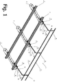
- Figure 1 illustrates schematically a perspective view of a combination according to an embodiment of the present invention.
- the combination is a railway 20 and a number of track-securing devices 1 for a track barrier for safeguarding or delimiting a section of the railway 20.
- the railway 20 comprises rails 2 and a number of railway sleepers 8.
- Each rail 2 has a foot 4, which may be fixed with at least one clamp mechanism to an underlying sleeper 8, see FIG. 5 .
- On one side of the railway 20 track-securing devices 1 are mounted.
- Each of the track-securing devices 1 comprises a bar holder 10 for holding a number of barrier bars 15, a fastening assembly 20 arranged for fastening the respective track-securing device 1 in a releasable manner to a rail 2 of the railway 20 and a retaining limb 30 arranged to connect the bar holder 10 to the fastening assembly 20.
- the bar holder 10 is primarily directed vertically and holds two barrier bars 15 at respective height positions.
- the retaining limb 30 may comprise a first part 30a and a second part 30b, wherein the first part 30a is telescopically displaceable arranged with respect to the second part 30b.
- the retaining limb 30 is arranged to displaceable position the bar holder 10 with respect to the fastening assembly 20 at a desired position with respect to the rail 2.
- Each of the track-securing devices 1 is fastened to the rail 2 near a railway sleeper 8 and the corresponding retaining limb 30 is positioned at least partly above the corresponding railway sleeper 8.
- Each of the track-securing devices 1 further comprises a slide 36, wherein the slide has a support element 38.
- the slide 36 is mounted onto the retaining limb 30 and is displaceable longitudinally on the retaining limb 30.
- the support element 38 protrudes from the retaining limb 30 downwards towards the railway sleeper 8.
- the support element 38 is arranged for supporting the retaining limb 30 on the railway sleeper 8.
- a protruding length of the support element is suitably selected to support the retaining limb 30 on the railway sleeper 8.
- FIGS. 2A - 2B An embodiment of the slide 36 is shown in FIGS. 2A - 2B .
- FIG. 2A - 2B illustrate schematically two different side views of a slide according to an embodiment of the present invention.
- the slide 36 has a tubular section 37, a support element 38 and a retaining element 39.
- the tubular section 37 has a cross-section having substantially rectangular shape, which is substantially conformal to a cross-section of the retaining limb 30, which also has a substantially rectangular shape.
- the tubular section 37 is arranged to enclose the retaining limb 30 and engage the four sides of the outer surface of the retaining limb 30. In this way, the slide 36 is easily displaceable along the retaining limb 30.
- the support element 38 protrudes from the tubular section 36, and thus from the retaining limb 30, over a predetermined length. In case the support element 38 is mounted onto the retaining limb 30, the support element 38 protrudes downwards towards the railway sleeper 8.
- the support element 38 in particular its protruding length, is arranged for support the retaining limb 30 on the railway sleeper 8.
- the support element 38 may have any suitable shape, such as a tubular shape.
- the retaining element 39 is arranged for retaining the slide 36 in a releasable manner at a position longitudinally on the retaining limb 30.
- the retaining element 39 may be a bolt, such as a wing bolt, which protrudes through the tubular section 36 to engage the retaining limb 30.
- any other retaining element may be provided, which is arranged for retaining the slide 36 in a releasable manner at a position longitudinally on the retaining limb 30.
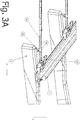
- Figure 3A illustrates schematically a detailed side view of a combination according to an embodiment of the present invention.
- the side view is along a longitudinal direction Y of a railway sleeper 8 (i.e. parallel to a lateral direction of the railway 20) and along a vertical direction Z.
- the combination comprises a rail 2, having a foot 4 which is fixed with at least one clamp mechanism 6 to an underlying railway sleeper 8, and a track-securing device 1 according to the invention.
- the fastening assembly 20 of the track-securing device 1 is fastened to an edge of the foot 4 of the rail 2.
- the retaining limb 30 is positioned above the railway sleeper 8.
- the top surface of the railway sleeper slopes downwards from the rail 2 towards an outer end of the railway sleeper 8.
- the retaining limb 30 may be directed substantially horizontal, as shown in FIG. 3A .
- the interdistance decreases between the retaining limb 30 and the railway sleeper 8, when moving along the retaining limb 30 towards the fastening assembly 20, due to the downward slope of the railway sleeper 8.
- the slide 36 is moved along the retaining limb 30 towards the fastening assembly 20 up to a position, where the support element 38 engages the top surface of the railway sleeper 8. In this position, the support element 38 supports the retaining limb 30.
- the retaining limb 30 may be inclined upwards from the fastening assembly 20 towards the bar holder 10 in the vertical direction Z. As such, the interdistance decreases even faster between the retaining limb 30 and the railway sleeper 8, when moving along the retaining limb 30 towards the fastening assembly 20.
- Figure 3B illustrates schematically a detailed side view of a combination according to another embodiment of the present invention.
- the side view is along a longitudinal direction Y of a railway sleeper 8 and along a vertical direction Z.
- the combination comprises a rail 2, having a foot 4 which is fixed with at least one clamp mechanism 6 to an underlying railway sleeper 8, and a track-securing device 1 according to the invention.
- the fastening assembly 20 of the track-securing device 1 is fastened to an edge of the foot 4 of the rail 2.
- the retaining limb 30 is positioned above the railway sleeper 8.
- the top surface of the railway sleeper 8 is substantially horizontal between the rail 2 and an outer end of the railway sleeper 8.
- the retaining limb 30 is directed upwards with respect to the vertical direction Z at an angle a. As such, the interdistance decreases between the retaining limb 30 and the railway sleeper 8, when moving along the retaining limb 30 towards the fastening assembly 20.
- the slide 36 is moved along the retaining limb 30 towards the fastening assembly 20 up to a position, where the support element 38 engages the horizontal top surface of the railway sleeper 8. In this position, the support element 38 supports the retaining limb 30.
- the retaining limb 30 may have a curved part, which is arranged above the railway sleeper 8, such that the retaining limb 30 converges towards the railway sleeper, when moving along the retaining limb 30 towards the fastening assembly 20.
- FIG. 4 illustrates schematically a detailed perspective view of a fastening assembly according to an embodiment of the present invention.
- the fastening assembly 20 has jaw 24, a hook 26 and a tensioning means 28.
- the jaw is arranged to engage onto an edge 5 of the foot 4 of the rail 2, see FIG. 5.
- Figure 5 illustrates schematically a detailed cross section of the fastening assembly according to the embodiment shown in FIG.4 along a longitudinal direction Y of a railway sleeper 8, wherein the fastening assembly 20 is fastened onto the rail 2.
- the jaw 24 is formed by a strip, which is bend into a U-shaped bow having two free ends 25. Each free end 25 comprising a recess 23, which is adapted to a profile of the edge 5 of the foot 4 of the rail 2, see FIG. 5 .
- the hook 26 is arranged to grasp onto the clamp mechanism 6 of the rail 2.
- the hook 26 has a tip 27 arranged to engage an element of the clamp mechanism 6, such as a clamping bolt, at a side of the clamp mechanism 6, which is arranged opposite to the edge 5 of the foot 4 in a horizontal direction Y of the foot 4, see FIG. 5 .
- the hook 26 is arranged for extending over the clamp mechanism 6.
- the tensioning means 28 is arranged for drawing on the hook 26 with respect to the jaw 24 to fasten the track-securing device 1 to the rail 2.
- the tensioning means 28 comprises a lever element for moving the hook towards the retaining limb 30 and a spring element 29 to tension the hook with respect to the jaw to fasten the track-securing device 1 to the rail 2.
- the hook 26 comprises a telescopic guiding section, having a tip part and a main part moveable with respect to one another, wherein the spring element 29 is accommodated.
- the spring element 29 connects the lever to the tip part of the hook 26. By the lever, the spring 29 can be tensioned, when moving the tip part with respect to the main part of the hook 26, thereby drawing the hook 26 onto the clamp mechanism 6 and drawing the jaw 24 onto the edge 5 of the foot 4 of the rail 2.
Landscapes
- Engineering & Computer Science (AREA)
- Architecture (AREA)
- Civil Engineering (AREA)
- Structural Engineering (AREA)
- Railway Tracks (AREA)
- Train Traffic Observation, Control, And Security (AREA)
Abstract
Description
- The field of the invention relates to a track-securing device for a track barrier for safeguarding or delimiting a section of a rail. The field of the invention further relates to a combination of a rail and a number of track-securing devices according to the present invention.
- A track-securing device for a track barrier for safeguarding or delimiting a section of a rail is known. Such a track-securing device is for instance described in
NL2006100 - The bar holder needs to be suitably supported near the rail in order to retain the position of the bar holder including the barrier bars in a height direction a stable manner. A demand exists to provide a track-securing device, which further increases a distance of the bar holder from the rail in order to improve safeguarding of a section of the rail. When the distance of the bar holder from the rail increases a positioning of the bar holder may become less stable. Additionally, the ground level and the ground surface material near the rail may differ considerably. Thus, depending on the ground level and the ground surface material the positioning of the track-securing device may be more cumbersome and take considerable effort to achieve.
- Moreover, a desire exists to provide a track-securing device for a track barrier for safeguarding or delimiting a section of a rail, wherein the track-securing device is easily and reliably installed onto the rail.
- According to a first aspect of the invention there is provided a track-securing device for a track barrier for safeguarding or delimiting a section of a rail, in particular of a railway line, the track-securing device having a bar holder for at least one barrier bar of the track barrier, in particular for two barrier bars, a fastening assembly arranged for fastening the track-securing device in a releasable manner onto a part of the rail, wherein the rail is fixed with at least one clamp mechanism to an underlying railway sleeper, and having a retaining limb arranged to connect the bar holder to the fastening assembly, wherein a slide is provided, said slide being mounted on the retaining limb, wherein the slide is displaceable longitudinally on the retaining limb and wherein the slide has a support element, wherein the support element protrudes from the retaining limb and is arranged for supporting the retaining limb on the railway sleeper.
- The slide is displaceable longitudinally on the retaining limb. In particular, the slide may be mounted onto the retaining limb between the fastening assembly and the bar holder. The slide has a support element, which protrudes from the retaining limb. The support element is arranged for supporting the retaining limb on the railway sleeper. In particular, the support element may protrude downwards towards the railway sleeper in an assembled state of the track-securing device and the rail (i.e. when the fastening assembly is connected to the part of the rail). The track-securing device may be fastened to a part of the rail in a first stage by using the fastening assembly. Said part of the rail may be a foot of the rail. In a second stage the track-securing device including the bar holder may be positioned in a height direction by sliding the slider along the retaining limb towards the fastening assembly until the protruding support element is supported onto the railway sleeper. In this way, the track-securing device including the bar holder is suitably supported on the railway sleeper. As the railway sleeper has a known height with respect to the rail, the height of the bar holder is easily controlled by the support element of the slider.
- The track-securing device according to the invention supports an easy instalment onto the rail and a reliable positioning of the track-securing device for safeguarding or delimiting a section of a rail. The track-securing device according to the invention supports a reliable positioning of the track-securing device for an increased distance of the bar holder from the rail. The preferred distance of the bar holder from the rail may be in the range 1.9 meter - 2.5 meter.
- In particular, a downward deflection of the retaining limb under a predefined vertical load is minimized by the use of the slide including the support element.
- In exemplary embodiments, the support element has a predetermined protruding length. The predetermined protruding length is selected to support the retaining limb on a railway sleeper. The protruding length and may be fixed.
- In alternative embodiments, the protruding length of the support element is adaptable. In an example, the protruding element comprises a telescopic section arranged for selectively adapting a protruding length of the support element.
- In an exemplary embodiment, the retaining limb and the fastening assembly cooperatively are arranged such that, in an assembled state of the track-securing device and the rail, the protruding element engages the railway sleeper, when sliding the slider along the retaining limb towards the fastening assembly. In the assembled state, the track-securing device is fastened to the part of the rail, such as the foot of the rail, by the fastening assembly. The protruding element engages a top surface of the railway sleeper, when sliding the slider along the retaining limb towards the fastening assembly. The fastening assembly positions the retaining limb near to the top surface of the railway sleeper at a desired distance from the top surface of the railway sleeper, when the fastening assembly fastens the track-securing device onto the part of the rail.
- Preferably, the fastening assembly is arranged for keeping the position of the retaining limb substantially stable above the top surface of the railway sleeper, when the fastening assembly fastens the track-securing device onto the part of the rail.
- Exemplary embodiments of the fastening assembly for positioning the retaining limb are discussed further in the description of the invention.
- In an exemplary embodiment, the retaining limb converges towards the railway sleeper, in an assembled state of the track-securing device and the rail, when moving along the retaining limb towards the fastening assembly. In this way, an interdistance decreases between the retaining limb and the railway sleeper, when moving along the retaining limb towards the fastening assembly. As the interdistance decreases along the retaining limb, the support element engages the railway sleeper at a position along the retaining limb wherein the interdistance is substantially equal to a protruding length of the support element.
- In embodiments, the top surface of the railway sleeper may slope downwards from the rail towards an outer end of the railway sleeper. In that case, the retaining limb may be directed substantially horizontal and the interdistance decreases between the retaining limb and the railway sleeper, when moving along the retaining limb towards the fastening assembly, due to the downward slope of the railway sleeper.
- In an exemplary embodiment, the retaining limb, in an assembled state of the track-securing device and the rail, is inclined upwards from the fastening assembly towards the bar holder in a vertical direction. The retaining limb is directed upwards with respect to a vertical direction. As such, the interdistance decreases between the retaining limb and the railway sleeper, when moving along the retaining limb towards the fastening assembly.
- In embodiments, the top surface of the railway sleeper may be substantially horizontal between the rail and an outer end of the railway sleeper. In that case, preferably the retaining limb is directed upwards with respect to the vertical direction. As such, the interdistance decreases between the retaining limb and the railway sleeper, when moving along the retaining limb towards the fastening assembly.
- In exemplary embodiments, the retaining limb may be substantially straight in the longitudinal direction, may have a curved part along the longitudinal direction, such as a curved part being inclined upwards from the fastening assembly towards the bar holder, and may have any other suitable shape for guiding a slide along its longitudinal direction.
- In an exemplary embodiment, the slide has a tubular section formed to at least partially embrace the retaining limb. The tubular section may partially or completely enclose the retaining limb. The tubular section supports a sliding of the slide along the retaining limb. The retaining limb may have a substantially circular cross section and may have a rectangular cross section. Preferably, the tubular section is shaped to slide over the outer surface of the retaining limb. Preferably, the inner surface of the tubular section has a cross section shape, which is similar to the cross section shape of the outer surface of the retaining limb. In case the retaining limb has a substantially circular cross section (having a certain diameter), preferably, the tubular section has an inner surface having substantially the same circular cross section (or same diameter).
- In an exemplary embodiment, a cross-section of each of the retaining limb and the tubular section has a substantially rectangular shape. Preferably, the rectangular cross section shape of the inner surface of the tubular section is similar to the rectangular cross section shape the outer surface of the retaining limb.
- In an exemplary embodiment, the slide has a retaining element arranged for retaining the slide in a releasable manner at a position longitudinally on the retaining limb. The retaining element retains the slide in the desired position. The desired position is the position of the slide for supporting the track-securing device onto the railway sleeper.
- In an exemplary embodiment, the retaining limb is arranged to displaceable position the bar holder with respect to the fastening assembly, wherein the retaining limb has a first part and a second part, wherein the first part is telescopically displaceable arranged with respect to the second part. The first part may be telescopically displaced with respect to the second part to shorten or to lengthen, respectively, the retaining limb. In this way, the bar holder is easily positioned at a desired distance with respect to the fastening assembly. The first part may be slideable with respect to the second part. The first part may be partially accommodated by the second part. Alternatively, the second part may be partially accommodated by the first part.
- In an exemplary embodiment, the retaining limb has a fastening element arranged for fastening the first part in a releasable manner with respect to the second part at a desired position of a plurality of positions longitudinally on the second part. In this way, the selected length of the retaining limb, which corresponds to the position of the first part with respect to the second part, is easily retained. The fastening element may be a pin, may be a bolt, may be a clamp, may be a joint and may be any other suitable fastening element.
- In an exemplary embodiment, the fastening assembly comprises a jaw arranged to engage onto an edge of the foot of the rail, a hook arranged to grasp onto the clamp mechanism and tensioning means arranged for drawing on the hook with respect to the jaw to fasten the track-securing device to the rail. In this way, the fastening assembly supports a simple and fast manner of fastening the track-securing device to the rail. The edge of the foot of the rail is normally easily accessible, especially near the railway sleeper. The hook is arranged to grasp onto the clamp mechanism. The hook may grasp a clamp, a bolt and/or a screw of the clamp mechanism. The tensioning means draw the hook with respect to the jaw, thereby fastening the track-securing device to the rail.
- In an exemplary embodiment, the jaw has a recess adapted to a profile of the edge of the foot of the rail. By the recess the jaw engages both over the edge of the foot as well as under the edge of the foot. In this way, the jaw cannot unintentionally disengage from the foot of the rail. Preferably, the recess is adapted to the profile of the edge of the foot of the rail in order to position the retaining limb at a desired position above a railway sleeper. In this way, a free play of the retaining limb in the vertical direction is minimized.
- In an exemplary embodiment, the jaw has a U-shaped bow having two free ends, each free end comprising a recess adapted to a profile of the edge of the foot of the rail. The U-shaped bow is easily manufactured and the weight of the jaw can be minimized by the U-shaped bow. The U-shaped bow supports a reliable positioning of the retaining limb in a height direction and in a lateral direction perpendicular to the longitudinal direction of the rail.
- In an exemplary embodiment, the hook is arranged for extending over the clamp mechanism, wherein the hook has a tip arranged to engage the clamp mechanism at a side of the clamp mechanism, which side is arranged opposite to the edge of the foot in a horizontal direction of the foot. The tip of the hook supports a tensioning of the fastening assembly in the horizontal direction of the foot. Preferably, the tip of the hook is arranged for engaging an element of the clamp mechanism, such as a clamping bolt.
- In an exemplary embodiment, the track-securing device including the fastening assembly is arranged for fastening the track-securing apparatus to the foot of the rail such that the retaining limb is inclined upwards from the fastening assembly towards the bar holder.
- In an exemplary embodiment, the track-securing device includes a number of barrier bars having a cross-section which is substantially rectangular shaped. The substantially rectangular shaped barrier bars are easily stacked and transported as a stack of barrier bars.
- In another aspect of the invention, a combination is provided of a rail, having a foot which is fixed with at least one clamp mechanism to an underlying railway sleeper, and a number of track-securing devices according to any one of the preceding claims, wherein each track-securing device is arranged partly above the corresponding railway sleeper, wherein the fastening assembly is fastened in a releasable manner onto a part of the rail, and wherein the support element of the slide is supported onto the corresponding railway sleeper.
- Preferably, said part of the rail is a foot of the rail.
- In an exemplary embodiment of the combination, barrier bars are held to provide a barrier between vertical parts of two adjacent track-securing devices.
- In particular embodiment, adjacent barrier bars are connected to one another in the longitudinal direction of the barrier bars by a connector element. A connector element may be a mounted onto each of the barrier bars at one end of the respective barrier bar, i.e. before mounting the respective barrier bar onto the corresponding track-securing device.
- In an exemplary embodiment of the combination, each of the barrier bars has a cross-section which is substantially rectangular shaped.
- The accompanying drawings are used to illustrate presently preferred non-limiting exemplary embodiments of devices of the present invention. The above and other advantages of the features and objects of the invention will become more apparent and the invention will be better understood from the following detailed description when read in conjunction with the accompanying drawings, in which:
-
Figure 1 illustrates schematically a perspective view of a combination according to an embodiment of the present invention; -
Figure 2A - 2B illustrate schematically two different side views of a slide according to an embodiment of the present invention; -
Figure 3A illustrates schematically a detailed side view of a combination according to an embodiment of the present invention; -
Figure 3B illustrates schematically a detailed side view of a combination according to another embodiment of the present invention; -
Figure 4 illustrates schematically a detailed perspective view of a fastening assembly according to an embodiment of the present invention; -
Figure 5 illustrates schematically a detailed cross section of the fastening assembly according to the embodiment shown inFIG.4 . -
Figure 1 illustrates schematically a perspective view of a combination according to an embodiment of the present invention. The combination is arailway 20 and a number of track-securingdevices 1 for a track barrier for safeguarding or delimiting a section of therailway 20. Therailway 20 comprisesrails 2 and a number ofrailway sleepers 8. Eachrail 2 has a foot 4, which may be fixed with at least one clamp mechanism to anunderlying sleeper 8, seeFIG. 5 . On one side of therailway 20 track-securingdevices 1 are mounted. Each of the track-securingdevices 1 comprises abar holder 10 for holding a number of barrier bars 15, afastening assembly 20 arranged for fastening the respective track-securingdevice 1 in a releasable manner to arail 2 of therailway 20 and a retaininglimb 30 arranged to connect thebar holder 10 to thefastening assembly 20. - The
bar holder 10 is primarily directed vertically and holds twobarrier bars 15 at respective height positions. - In embodiments, the retaining
limb 30 may comprise afirst part 30a and asecond part 30b, wherein thefirst part 30a is telescopically displaceable arranged with respect to thesecond part 30b. As such, the retaininglimb 30 is arranged to displaceable position thebar holder 10 with respect to thefastening assembly 20 at a desired position with respect to therail 2. - Each of the track-securing
devices 1 is fastened to therail 2 near arailway sleeper 8 and the corresponding retaininglimb 30 is positioned at least partly above the correspondingrailway sleeper 8. - Each of the track-securing
devices 1 further comprises aslide 36, wherein the slide has asupport element 38. Theslide 36 is mounted onto the retaininglimb 30 and is displaceable longitudinally on the retaining limb 30.Thesupport element 38 protrudes from the retaininglimb 30 downwards towards therailway sleeper 8. Thesupport element 38 is arranged for supporting the retaininglimb 30 on therailway sleeper 8. A protruding length of the support element is suitably selected to support the retaininglimb 30 on therailway sleeper 8. - An embodiment of the
slide 36 is shown inFIGS. 2A - 2B . -
Figure 2A - 2B illustrate schematically two different side views of a slide according to an embodiment of the present invention. Theslide 36 has atubular section 37, asupport element 38 and a retainingelement 39. Thetubular section 37 has a cross-section having substantially rectangular shape, which is substantially conformal to a cross-section of the retaininglimb 30, which also has a substantially rectangular shape. Thetubular section 37 is arranged to enclose the retaininglimb 30 and engage the four sides of the outer surface of the retaininglimb 30. In this way, theslide 36 is easily displaceable along the retaininglimb 30. - The
support element 38 protrudes from thetubular section 36, and thus from the retaininglimb 30, over a predetermined length. In case thesupport element 38 is mounted onto the retaininglimb 30, thesupport element 38 protrudes downwards towards therailway sleeper 8. Thesupport element 38, in particular its protruding length, is arranged for support the retaininglimb 30 on therailway sleeper 8. Thesupport element 38 may have any suitable shape, such as a tubular shape. - The retaining
element 39 is arranged for retaining theslide 36 in a releasable manner at a position longitudinally on the retaininglimb 30. The retainingelement 39 may be a bolt, such as a wing bolt, which protrudes through thetubular section 36 to engage the retaininglimb 30. - Alternatively, any other retaining element may be provided, which is arranged for retaining the
slide 36 in a releasable manner at a position longitudinally on the retaininglimb 30. -
Figure 3A illustrates schematically a detailed side view of a combination according to an embodiment of the present invention. The side view is along a longitudinal direction Y of a railway sleeper 8 (i.e. parallel to a lateral direction of the railway 20) and along a vertical direction Z. The combination comprises arail 2, having a foot 4 which is fixed with at least one clamp mechanism 6 to anunderlying railway sleeper 8, and a track-securingdevice 1 according to the invention. - The
fastening assembly 20 of the track-securingdevice 1 is fastened to an edge of the foot 4 of therail 2. The retaininglimb 30 is positioned above therailway sleeper 8. In this embodiment, the top surface of the railway sleeper slopes downwards from therail 2 towards an outer end of therailway sleeper 8. In this embodiment, the retaininglimb 30 may be directed substantially horizontal, as shown inFIG. 3A . The interdistance decreases between the retaininglimb 30 and therailway sleeper 8, when moving along the retaininglimb 30 towards thefastening assembly 20, due to the downward slope of therailway sleeper 8. Theslide 36 is moved along the retaininglimb 30 towards thefastening assembly 20 up to a position, where thesupport element 38 engages the top surface of therailway sleeper 8. In this position, thesupport element 38 supports the retaininglimb 30. - Alternatively, the retaining
limb 30 may be inclined upwards from thefastening assembly 20 towards thebar holder 10 in the vertical direction Z. As such, the interdistance decreases even faster between the retaininglimb 30 and therailway sleeper 8, when moving along the retaininglimb 30 towards thefastening assembly 20. -
Figure 3B illustrates schematically a detailed side view of a combination according to another embodiment of the present invention. The side view is along a longitudinal direction Y of arailway sleeper 8 and along a vertical direction Z. The combination comprises arail 2, having a foot 4 which is fixed with at least one clamp mechanism 6 to anunderlying railway sleeper 8, and a track-securingdevice 1 according to the invention. - The
fastening assembly 20 of the track-securingdevice 1 is fastened to an edge of the foot 4 of therail 2. The retaininglimb 30 is positioned above therailway sleeper 8. - In this embodiment, the top surface of the
railway sleeper 8 is substantially horizontal between therail 2 and an outer end of therailway sleeper 8. The retaininglimb 30 is directed upwards with respect to the vertical direction Z at an angle a. As such, the interdistance decreases between the retaininglimb 30 and therailway sleeper 8, when moving along the retaininglimb 30 towards thefastening assembly 20. Theslide 36 is moved along the retaininglimb 30 towards thefastening assembly 20 up to a position, where thesupport element 38 engages the horizontal top surface of therailway sleeper 8. In this position, thesupport element 38 supports the retaininglimb 30. - Alternatively or additionally, the retaining
limb 30 may have a curved part, which is arranged above therailway sleeper 8, such that the retaininglimb 30 converges towards the railway sleeper, when moving along the retaininglimb 30 towards thefastening assembly 20. - In both embodiments shown in
Figure 3A and3B downward deflection of the retaininglimb 30 under a predefined vertical load is tested by applying a load of 1.2 kN onto the retaininglimb 30 at a position close to thebar holder 10 according to DIN 16704-2-2. Due to the use of thesupport element 38, which supports the retaininglimb 30 on therailway sleeper 8, the downward deflection of the retaininglimb 30 under the predefined vertical load is minimized to less than 200 mm by the use of theslide 36 including thesupport element 38. -
Figure 4 illustrates schematically a detailed perspective view of a fastening assembly according to an embodiment of the present invention. Thefastening assembly 20 hasjaw 24, ahook 26 and a tensioning means 28. The jaw is arranged to engage onto anedge 5 of the foot 4 of therail 2, seeFIG. 5. Figure 5 illustrates schematically a detailed cross section of the fastening assembly according to the embodiment shown inFIG.4 along a longitudinal direction Y of arailway sleeper 8, wherein thefastening assembly 20 is fastened onto therail 2. - The
jaw 24 is formed by a strip, which is bend into a U-shaped bow having two free ends 25. Eachfree end 25 comprising arecess 23, which is adapted to a profile of theedge 5 of the foot 4 of therail 2, seeFIG. 5 . - The
hook 26 is arranged to grasp onto the clamp mechanism 6 of therail 2. Thehook 26 has atip 27 arranged to engage an element of the clamp mechanism 6, such as a clamping bolt, at a side of the clamp mechanism 6, which is arranged opposite to theedge 5 of the foot 4 in a horizontal direction Y of the foot 4, seeFIG. 5 . Thehook 26 is arranged for extending over the clamp mechanism 6. - The tensioning means 28 is arranged for drawing on the
hook 26 with respect to thejaw 24 to fasten the track-securingdevice 1 to therail 2. The tensioning means 28 comprises a lever element for moving the hook towards the retaininglimb 30 and aspring element 29 to tension the hook with respect to the jaw to fasten the track-securingdevice 1 to therail 2. Thehook 26 comprises a telescopic guiding section, having a tip part and a main part moveable with respect to one another, wherein thespring element 29 is accommodated. Thespring element 29 connects the lever to the tip part of thehook 26. By the lever, thespring 29 can be tensioned, when moving the tip part with respect to the main part of thehook 26, thereby drawing thehook 26 onto the clamp mechanism 6 and drawing thejaw 24 onto theedge 5 of the foot 4 of therail 2. - It should be appreciated by those skilled in the art that any block diagrams herein represent conceptual views of illustrative units or modules embodying the principles of the invention.
- Whilst the principles of the invention have been set out above in connection with specific embodiments, it is to be understood that this description is merely made by way of example and not as a limitation of the scope of protection which is determined by the appended claims.
Claims (16)
- A track-securing device (1) for a track barrier for safeguarding or delimiting a section of a rail (2), in particular of a railway line, having a bar holder (10) for at least one barrier bar (15) of the track barrier, in particular for two barrier bars (15), having a fastening assembly (20) arranged for fastening the track-securing device (1) in a releasable manner onto a part (4) of the rail (2), such as a foot (4) of the rail (2), wherein the part (4) is fixed with at least one clamp mechanism (6) to an underlying railway sleeper (8), and having a retaining limb (30) arranged to connect the bar holder (10) to the fastening assembly (20), wherein a slide (36) is provided, said slide (36) being mounted on the retaining limb (30), wherein the slide (36) is displaceable longitudinally on the retaining limb (30) and wherein the slide has a support element (38), wherein the support element (38) protrudes from the retaining limb (30) and is arranged for supporting the retaining limb (30) on the railway sleeper (8).
- The track-securing device (1) for a track barrier according to claim 1, wherein the retaining limb (30) and the fastening assembly (20) cooperatively are arranged such that, in an assembled state of the track-securing device and the rail (2), the support element engages the railway sleeper, when sliding the slider along the retaining limb towards the fastening assembly.
- The track-securing device (1) for a track barrier according to claim 2, wherein the retaining limb (30) converges towards the railway sleeper (8), in an assembled state of the track-securing device and the rail (2), when moving along the retaining limb (30) towards the fastening assembly (20).
- The track-securing device (1) for a track barrier according to claim 2 or 3, wherein the retaining limb (30), in an assembled state of the track-securing device and the rail (2), is inclined upwards from the fastening assembly (20) towards the bar holder (15).
- The track-securing device (1) for a track barrier according to any one of the preceding claims, wherein the slide (36) has a tubular section (37) formed to at least partially embrace the retaining limb (30), in an assembled state of the track-securing device and the rail (2).
- The track-securing device (1) for a track barrier according to any one of the preceding claims, wherein a cross-section of each of the retaining limb (30) and the tubular section (37) has a substantially rectangular shape.
- The track-securing device (1) for a track barrier according to any one of the preceding claims, wherein the slide (36) has a retaining element (39) arranged for retaining the slide (36) in a releasable manner at a position longitudinally on the retaining limb (30).
- The track-securing device (1) for a track barrier according to any one of the preceding claims, wherein the retaining limb (30) is arranged to displaceable position the bar holder (10) with respect to the fastening assembly (20), wherein the retaining limb (30) has a first part (30a) and a second part (30b), wherein the first part is telescopically displaceable arranged with respect to the second part.
- The track-securing device (1) for a track barrier according to claim 8, wherein the retaining limb (36) has a fastening element arranged for fastening the first part in a releasable manner with respect to the second part at a desired position of a plurality of positions longitudinally on the second part.
- The track-securing device (1) for a track barrier according to any one of the preceding claims, wherein the fastening assembly (20) comprises a jaw (24) arranged to engage onto an edge (5) of the foot (4) of the rail (2), a hook (26) arranged to grasp onto the clamp mechanism (6) and tensioning means (28) arranged for drawing on the hook with respect to the jaw to fasten the track-securing device to the rail (2).
- The track-securing device (1) for a track barrier according to claim 10, wherein the jaw (24) has a recess (23) adapted to a profile of the edge (5) of the foot (4) of the rail (2).
- The track-securing device (1) for a track barrier according to claim 10 or 11, wherein the jaw (24) has a U-shaped bow having two free ends, each free end comprising a recess (23) adapted to a profile of the edge (5) of the foot (4) of the rail (2).
- The track-securing device (1) for a track barrier according to any one of claims 10 - 12, wherein the hook (26) is arranged for extending over the clamp mechanism (6), wherein the hook (26) has a tip arranged to engage an element of the clamp mechanism (6), such as a clamping bolt, at a side of the clamp mechanism (6), which is arranged opposite to the edge of the foot (4) in a horizontal direction of the foot (4).
- The track-securing device (1) for a track barrier according to any one of the preceding claims, wherein the track-securing device including the fastening assembly (20) is arranged for fastening the track-securing apparatus (1) to the foot (4) of the rail (2) such that the retaining limb (30) is inclined upwards from the fastening assembly (20) towards the bar holder (15).
- The track-securing device (1) for a track barrier according to any one of the preceding claims, wherein the track-securing device includes a number of barrier bars (15) having a cross-section which is substantially rectangular shaped.
- A combination of a rail (2), having a foot (4) which is fixed with at least one clamp mechanism (6) to an underlying railway sleeper (8), and a number of track-securing devices according to any one of the preceding claims, wherein each track-securing device is arranged partly above the corresponding railway sleeper (8), wherein the fastening assembly (20) is fastened in a releasable manner onto the part (4) of the rail (2), and wherein the support element (38) of the slide (36) is supported onto the corresponding railway sleeper (8).
Priority Applications (9)
| Application Number | Priority Date | Filing Date | Title |
|---|---|---|---|
| RS20220423A RS63222B1 (en) | 2018-12-21 | 2018-12-21 | TRACK SAFETY DEVICE FOR TRACK LOCKING TO PROTECT THE RAIL SEGMENT |
| PL18215605T PL3670742T3 (en) | 2018-12-21 | 2018-12-21 | A track-securing device for a track barrier for safeguarding a section of a rail |
| HRP20220566TT HRP20220566T1 (en) | 2018-12-21 | 2018-12-21 | A track-securing device for a track barrier for safeguarding a section of a rail |
| SI201830659T SI3670742T1 (en) | 2018-12-21 | 2018-12-21 | A track-securing device for a track barrier for safeguarding a section of a rail |
| DK18215605.9T DK3670742T3 (en) | 2018-12-21 | 2018-12-21 | TRACK SECURITY DEVICE FOR A TRACK BARRIER FOR SECURING A RAIL SECTION |
| ES18215605T ES2912610T3 (en) | 2018-12-21 | 2018-12-21 | A track fixing device for a track barrier to protect a section of a rail |
| PT182156059T PT3670742T (en) | 2018-12-21 | 2018-12-21 | A track-securing device for a track barrier for safeguarding or delimiting a section of a rail; a combination of a rail and a number of track-securing devices |
| HUE18215605A HUE058946T2 (en) | 2018-12-21 | 2018-12-21 | A track-securing device for a track barrier for safeguarding a section of a rail |
| EP18215605.9A EP3670742B1 (en) | 2018-12-21 | 2018-12-21 | A track-securing device for a track barrier for safeguarding a section of a rail |
Applications Claiming Priority (1)
| Application Number | Priority Date | Filing Date | Title |
|---|---|---|---|
| EP18215605.9A EP3670742B1 (en) | 2018-12-21 | 2018-12-21 | A track-securing device for a track barrier for safeguarding a section of a rail |
Publications (2)
| Publication Number | Publication Date |
|---|---|
| EP3670742A1 true EP3670742A1 (en) | 2020-06-24 |
| EP3670742B1 EP3670742B1 (en) | 2022-04-06 |
Family
ID=64901420
Family Applications (1)
| Application Number | Title | Priority Date | Filing Date |
|---|---|---|---|
| EP18215605.9A Active EP3670742B1 (en) | 2018-12-21 | 2018-12-21 | A track-securing device for a track barrier for safeguarding a section of a rail |
Country Status (9)
| Country | Link |
|---|---|
| EP (1) | EP3670742B1 (en) |
| DK (1) | DK3670742T3 (en) |
| ES (1) | ES2912610T3 (en) |
| HR (1) | HRP20220566T1 (en) |
| HU (1) | HUE058946T2 (en) |
| PL (1) | PL3670742T3 (en) |
| PT (1) | PT3670742T (en) |
| RS (1) | RS63222B1 (en) |
| SI (1) | SI3670742T1 (en) |
Cited By (4)
| Publication number | Priority date | Publication date | Assignee | Title |
|---|---|---|---|---|
| EP3936663A1 (en) * | 2020-07-08 | 2022-01-12 | ARC Allround Cleaning Rheinfelden AG | Track protection fence system |
| EP3936664A1 (en) * | 2020-07-08 | 2022-01-12 | ARC Allround Cleaning Rheinfelden AG | Fastening system for fastening a railway additional device to a rail system and track fence system |
| EP3978685A1 (en) * | 2020-11-03 | 2022-04-06 | Ten Hove Group B.V. | Track-mounting device for mounting to a rail of a track |
| WO2026073564A1 (en) | 2024-10-04 | 2026-04-09 | Ten Hove Group B.V. | Track-securing device for temporarily fastening a holder to a rail, method for temporarily fastening a holder to a rail and method for releasing a holder from a rail |
Citations (4)
| Publication number | Priority date | Publication date | Assignee | Title |
|---|---|---|---|---|
| DE9409792U1 (en) * | 1994-05-17 | 1994-09-01 | Joseph Hubert Bauunternehmung GmbH & Co. KG, 90429 Nürnberg | Bracket arrangement for the guiding rope of guiding rope controlled track construction machines, for flutter lines, rigid track barriers or the like. |
| EP0708204A1 (en) * | 1994-10-17 | 1996-04-24 | LEONHARD WEISS GmbH & Co. NIEDERLASSUNG CRAILSHEIM | Angular post for railroad security fence |
| DE29712442U1 (en) * | 1997-07-15 | 1998-11-12 | Hawart Sondermaschinenbau GmbH, 27777 Ganderkesee | Mobile locking device |
| NL2006100C2 (en) | 2011-01-31 | 2012-08-01 | Evert Ijssel | BRACKET CLAMP FOR FIXING A FENCE TO A RAIL BAR. |
-
2018
- 2018-12-21 EP EP18215605.9A patent/EP3670742B1/en active Active
- 2018-12-21 HR HRP20220566TT patent/HRP20220566T1/en unknown
- 2018-12-21 SI SI201830659T patent/SI3670742T1/en unknown
- 2018-12-21 PL PL18215605T patent/PL3670742T3/en unknown
- 2018-12-21 ES ES18215605T patent/ES2912610T3/en active Active
- 2018-12-21 PT PT182156059T patent/PT3670742T/en unknown
- 2018-12-21 HU HUE18215605A patent/HUE058946T2/en unknown
- 2018-12-21 RS RS20220423A patent/RS63222B1/en unknown
- 2018-12-21 DK DK18215605.9T patent/DK3670742T3/en active
Patent Citations (4)
| Publication number | Priority date | Publication date | Assignee | Title |
|---|---|---|---|---|
| DE9409792U1 (en) * | 1994-05-17 | 1994-09-01 | Joseph Hubert Bauunternehmung GmbH & Co. KG, 90429 Nürnberg | Bracket arrangement for the guiding rope of guiding rope controlled track construction machines, for flutter lines, rigid track barriers or the like. |
| EP0708204A1 (en) * | 1994-10-17 | 1996-04-24 | LEONHARD WEISS GmbH & Co. NIEDERLASSUNG CRAILSHEIM | Angular post for railroad security fence |
| DE29712442U1 (en) * | 1997-07-15 | 1998-11-12 | Hawart Sondermaschinenbau GmbH, 27777 Ganderkesee | Mobile locking device |
| NL2006100C2 (en) | 2011-01-31 | 2012-08-01 | Evert Ijssel | BRACKET CLAMP FOR FIXING A FENCE TO A RAIL BAR. |
Cited By (4)
| Publication number | Priority date | Publication date | Assignee | Title |
|---|---|---|---|---|
| EP3936663A1 (en) * | 2020-07-08 | 2022-01-12 | ARC Allround Cleaning Rheinfelden AG | Track protection fence system |
| EP3936664A1 (en) * | 2020-07-08 | 2022-01-12 | ARC Allround Cleaning Rheinfelden AG | Fastening system for fastening a railway additional device to a rail system and track fence system |
| EP3978685A1 (en) * | 2020-11-03 | 2022-04-06 | Ten Hove Group B.V. | Track-mounting device for mounting to a rail of a track |
| WO2026073564A1 (en) | 2024-10-04 | 2026-04-09 | Ten Hove Group B.V. | Track-securing device for temporarily fastening a holder to a rail, method for temporarily fastening a holder to a rail and method for releasing a holder from a rail |
Also Published As
| Publication number | Publication date |
|---|---|
| PT3670742T (en) | 2022-07-13 |
| RS63222B1 (en) | 2022-06-30 |
| PL3670742T3 (en) | 2022-06-13 |
| ES2912610T3 (en) | 2022-05-26 |
| EP3670742B1 (en) | 2022-04-06 |
| DK3670742T3 (en) | 2022-05-02 |
| HRP20220566T1 (en) | 2022-06-10 |
| HUE058946T2 (en) | 2022-09-28 |
| SI3670742T1 (en) | 2022-06-30 |
Similar Documents
| Publication | Publication Date | Title |
|---|---|---|
| EP3670742B1 (en) | A track-securing device for a track barrier for safeguarding a section of a rail | |
| CN109642434B (en) | Vehicle Roof Support Assembly | |
| CN104853958B (en) | Roof base crossbeam for motor vehicle | |
| KR100956008B1 (en) | Rail Temporary Fixture for Track Construction of Maglev Railway | |
| US9814957B2 (en) | Holding apparatus for a net of a table-tennis table | |
| US8789809B2 (en) | Auxiliary device for alignment of floor boards when laying plank flooring | |
| JP6552958B2 (en) | Ski carrier clamp | |
| US10544555B1 (en) | Roadway barrier apparatus | |
| KR100956009B1 (en) | Guide rail temporary clamping apparatus for installing track structure for magnetically levitated railway | |
| CN104720390A (en) | Sliding rail assembly | |
| AT394653B (en) | DRAWER | |
| US8459600B2 (en) | Trestle stabilizing device | |
| KR101311629B1 (en) | Fastening system for fastening a plate within an enclosure for electric installations | |
| US11897523B2 (en) | Universal track derailer assembly | |
| SE538860C2 (en) | Flexible fastening unit for a beam | |
| KR101621920B1 (en) | Apparatus for Supporting Guide Rail of Magnetic Levitation Train | |
| CN109489983B (en) | Fuel system test bench | |
| NL2006119C2 (en) | CLAMP MECHANISM FOR LOCKING AT LEAST AN OBJECT TO A RAIL AND A COMPOSITION. | |
| KR101621923B1 (en) | Track Structure for Magnetic Levitation Train Capable of Height Control of Guide Rail | |
| AT517023B1 (en) | Soft trolley | |
| CN107750217B (en) | Coupling device for traction cables for coupling vehicles to means of transport | |
| KR20100025561A (en) | Guide rail temporary clamping apparatus for installing track structure for magnetically levitated railway | |
| EP1652415A2 (en) | Device for equipping flat substrates with electrical components | |
| EP3978685B1 (en) | Track-mounting device for mounting to a rail of a track | |
| KR101382117B1 (en) | Seat rail locking apparatus of vehicle |
Legal Events
| Date | Code | Title | Description |
|---|---|---|---|
| REG | Reference to a national code |
Ref country code: HR Ref legal event code: TUEP Ref document number: P20220566T Country of ref document: HR |
|
| PUAI | Public reference made under article 153(3) epc to a published international application that has entered the european phase |
Free format text: ORIGINAL CODE: 0009012 |
|
| STAA | Information on the status of an ep patent application or granted ep patent |
Free format text: STATUS: THE APPLICATION HAS BEEN PUBLISHED |
|
| AK | Designated contracting states |
Kind code of ref document: A1 Designated state(s): AL AT BE BG CH CY CZ DE DK EE ES FI FR GB GR HR HU IE IS IT LI LT LU LV MC MK MT NL NO PL PT RO RS SE SI SK SM TR |
|
| AX | Request for extension of the european patent |
Extension state: BA ME |
|
| STAA | Information on the status of an ep patent application or granted ep patent |
Free format text: STATUS: REQUEST FOR EXAMINATION WAS MADE |
|
| RBV | Designated contracting states (corrected) |
Designated state(s): AL AT BE BG CH CY CZ DE DK EE ES FI FR GB GR HR HU IE IS IT LI LT LU LV MC MK MT NL NO PL PT RO RS SE SI SK SM TR |
|
| 17P | Request for examination filed |
Effective date: 20201224 |
|
| GRAJ | Information related to disapproval of communication of intention to grant by the applicant or resumption of examination proceedings by the epo deleted |
Free format text: ORIGINAL CODE: EPIDOSDIGR1 |
|
| STAA | Information on the status of an ep patent application or granted ep patent |
Free format text: STATUS: GRANT OF PATENT IS INTENDED |
|
| GRAP | Despatch of communication of intention to grant a patent |
Free format text: ORIGINAL CODE: EPIDOSNIGR1 |
|
| RIC1 | Information provided on ipc code assigned before grant |
Ipc: B61L 29/02 20060101ALN20210810BHEP Ipc: E01B 17/00 20060101ALN20210810BHEP Ipc: E01F 13/02 20060101ALI20210810BHEP Ipc: E01B 26/00 20060101AFI20210810BHEP |
|
| INTG | Intention to grant announced |
Effective date: 20210910 |
|
| GRAS | Grant fee paid |
Free format text: ORIGINAL CODE: EPIDOSNIGR3 |
|
| GRAA | (expected) grant |
Free format text: ORIGINAL CODE: 0009210 |
|
| STAA | Information on the status of an ep patent application or granted ep patent |
Free format text: STATUS: THE PATENT HAS BEEN GRANTED |
|
| AK | Designated contracting states |
Kind code of ref document: B1 Designated state(s): AL AT BE BG CH CY CZ DE DK EE ES FI FR GB GR HR HU IE IS IT LI LT LU LV MC MK MT NL NO PL PT RO RS SE SI SK SM TR |
|
| REG | Reference to a national code |
Ref country code: GB Ref legal event code: FG4D |
|
| REG | Reference to a national code |
Ref country code: CH Ref legal event code: EP |
|
| REG | Reference to a national code |
Ref country code: AT Ref legal event code: REF Ref document number: 1481442 Country of ref document: AT Kind code of ref document: T Effective date: 20220415 |
|
| REG | Reference to a national code |
Ref country code: IE Ref legal event code: FG4D |
|
| REG | Reference to a national code |
Ref country code: DE Ref legal event code: R096 Ref document number: 602018033296 Country of ref document: DE |
|
| REG | Reference to a national code |
Ref country code: DK Ref legal event code: T3 Effective date: 20220429 |
|
| REG | Reference to a national code |
Ref country code: FI Ref legal event code: FGE |
|
| REG | Reference to a national code |
Ref country code: RO Ref legal event code: EPE |
|
| REG | Reference to a national code |
Ref country code: NL Ref legal event code: FP |
|
| REG | Reference to a national code |
Ref country code: SE Ref legal event code: TRGR |
|
| REG | Reference to a national code |
Ref country code: ES Ref legal event code: FG2A Ref document number: 2912610 Country of ref document: ES Kind code of ref document: T3 Effective date: 20220526 |
|
| REG | Reference to a national code |
Ref country code: HR Ref legal event code: T1PR Ref document number: P20220566 Country of ref document: HR |
|
| REG | Reference to a national code |
Ref country code: NO Ref legal event code: T2 Effective date: 20220406 |
|
| REG | Reference to a national code |
Ref country code: PT Ref legal event code: SC4A Ref document number: 3670742 Country of ref document: PT Date of ref document: 20220713 Kind code of ref document: T Free format text: AVAILABILITY OF NATIONAL TRANSLATION Effective date: 20220706 |
|
| REG | Reference to a national code |
Ref country code: LT Ref legal event code: MG9D |
|
| REG | Reference to a national code |
Ref country code: HU Ref legal event code: AG4A Ref document number: E058946 Country of ref document: HU |
|
| PG25 | Lapsed in a contracting state [announced via postgrant information from national office to epo] |
Ref country code: LT Free format text: LAPSE BECAUSE OF FAILURE TO SUBMIT A TRANSLATION OF THE DESCRIPTION OR TO PAY THE FEE WITHIN THE PRESCRIBED TIME-LIMIT Effective date: 20220406 Ref country code: GR Free format text: LAPSE BECAUSE OF FAILURE TO SUBMIT A TRANSLATION OF THE DESCRIPTION OR TO PAY THE FEE WITHIN THE PRESCRIBED TIME-LIMIT Effective date: 20220707 |
|
| PG25 | Lapsed in a contracting state [announced via postgrant information from national office to epo] |
Ref country code: LV Free format text: LAPSE BECAUSE OF FAILURE TO SUBMIT A TRANSLATION OF THE DESCRIPTION OR TO PAY THE FEE WITHIN THE PRESCRIBED TIME-LIMIT Effective date: 20220406 Ref country code: IS Free format text: LAPSE BECAUSE OF FAILURE TO SUBMIT A TRANSLATION OF THE DESCRIPTION OR TO PAY THE FEE WITHIN THE PRESCRIBED TIME-LIMIT Effective date: 20220806 |
|
| REG | Reference to a national code |
Ref country code: HR Ref legal event code: ODRP Ref document number: P20220566 Country of ref document: HR Payment date: 20221207 Year of fee payment: 5 |
|
| REG | Reference to a national code |
Ref country code: DE Ref legal event code: R097 Ref document number: 602018033296 Country of ref document: DE |
|
| PG25 | Lapsed in a contracting state [announced via postgrant information from national office to epo] |
Ref country code: SM Free format text: LAPSE BECAUSE OF FAILURE TO SUBMIT A TRANSLATION OF THE DESCRIPTION OR TO PAY THE FEE WITHIN THE PRESCRIBED TIME-LIMIT Effective date: 20220406 Ref country code: EE Free format text: LAPSE BECAUSE OF FAILURE TO SUBMIT A TRANSLATION OF THE DESCRIPTION OR TO PAY THE FEE WITHIN THE PRESCRIBED TIME-LIMIT Effective date: 20220406 |
|
| PLBE | No opposition filed within time limit |
Free format text: ORIGINAL CODE: 0009261 |
|
| STAA | Information on the status of an ep patent application or granted ep patent |
Free format text: STATUS: NO OPPOSITION FILED WITHIN TIME LIMIT |
|
| 26N | No opposition filed |
Effective date: 20230110 |
|
| PG25 | Lapsed in a contracting state [announced via postgrant information from national office to epo] |
Ref country code: AL Free format text: LAPSE BECAUSE OF FAILURE TO SUBMIT A TRANSLATION OF THE DESCRIPTION OR TO PAY THE FEE WITHIN THE PRESCRIBED TIME-LIMIT Effective date: 20220406 |
|
| P01 | Opt-out of the competence of the unified patent court (upc) registered |
Effective date: 20230507 |
|
| REG | Reference to a national code |
Ref country code: AT Ref legal event code: UEP Ref document number: 1481442 Country of ref document: AT Kind code of ref document: T Effective date: 20220406 |
|
| REG | Reference to a national code |
Ref country code: HR Ref legal event code: ODRP Ref document number: P20220566 Country of ref document: HR Payment date: 20231117 Year of fee payment: 6 |
|
| PG25 | Lapsed in a contracting state [announced via postgrant information from national office to epo] |
Ref country code: CY Free format text: LAPSE BECAUSE OF FAILURE TO SUBMIT A TRANSLATION OF THE DESCRIPTION OR TO PAY THE FEE WITHIN THE PRESCRIBED TIME-LIMIT Effective date: 20220406 |
|
| PG25 | Lapsed in a contracting state [announced via postgrant information from national office to epo] |
Ref country code: MK Free format text: LAPSE BECAUSE OF FAILURE TO SUBMIT A TRANSLATION OF THE DESCRIPTION OR TO PAY THE FEE WITHIN THE PRESCRIBED TIME-LIMIT Effective date: 20220406 |
|
| PG25 | Lapsed in a contracting state [announced via postgrant information from national office to epo] |
Ref country code: MC Free format text: LAPSE BECAUSE OF FAILURE TO SUBMIT A TRANSLATION OF THE DESCRIPTION OR TO PAY THE FEE WITHIN THE PRESCRIBED TIME-LIMIT Effective date: 20220406 |
|
| PG25 | Lapsed in a contracting state [announced via postgrant information from national office to epo] |
Ref country code: TR Free format text: LAPSE BECAUSE OF FAILURE TO SUBMIT A TRANSLATION OF THE DESCRIPTION OR TO PAY THE FEE WITHIN THE PRESCRIBED TIME-LIMIT Effective date: 20220406 Ref country code: MC Free format text: LAPSE BECAUSE OF FAILURE TO SUBMIT A TRANSLATION OF THE DESCRIPTION OR TO PAY THE FEE WITHIN THE PRESCRIBED TIME-LIMIT Effective date: 20220406 |
|
| PG25 | Lapsed in a contracting state [announced via postgrant information from national office to epo] |
Ref country code: MT Free format text: LAPSE BECAUSE OF FAILURE TO SUBMIT A TRANSLATION OF THE DESCRIPTION OR TO PAY THE FEE WITHIN THE PRESCRIBED TIME-LIMIT Effective date: 20220406 |
|
| REG | Reference to a national code |
Ref country code: HR Ref legal event code: ODRP Ref document number: P20220566 Country of ref document: HR Payment date: 20241205 Year of fee payment: 7 |
|
| PGFP | Annual fee paid to national office [announced via postgrant information from national office to epo] |
Ref country code: PT Payment date: 20251203 Year of fee payment: 8 |
|
| REG | Reference to a national code |
Ref country code: CH Ref legal event code: U11 Free format text: ST27 STATUS EVENT CODE: U-0-0-U10-U11 (AS PROVIDED BY THE NATIONAL OFFICE) Effective date: 20260101 |
|
| REG | Reference to a national code |
Ref country code: HR Ref legal event code: ODRP Ref document number: P20220566 Country of ref document: HR Payment date: 20251209 Year of fee payment: 8 |
|
| PGFP | Annual fee paid to national office [announced via postgrant information from national office to epo] |
Ref country code: DE Payment date: 20251212 Year of fee payment: 8 |
|
| PGFP | Annual fee paid to national office [announced via postgrant information from national office to epo] |
Ref country code: GB Payment date: 20251105 Year of fee payment: 8 |
|
| PGFP | Annual fee paid to national office [announced via postgrant information from national office to epo] |
Ref country code: NO Payment date: 20251209 Year of fee payment: 8 |
|
| PGFP | Annual fee paid to national office [announced via postgrant information from national office to epo] |
Ref country code: AT Payment date: 20251212 Year of fee payment: 8 |
|
| PGFP | Annual fee paid to national office [announced via postgrant information from national office to epo] |
Ref country code: FI Payment date: 20251212 Year of fee payment: 8 Ref country code: DK Payment date: 20251215 Year of fee payment: 8 |
|
| PGFP | Annual fee paid to national office [announced via postgrant information from national office to epo] |
Ref country code: LU Payment date: 20251205 Year of fee payment: 8 Ref country code: HR Payment date: 20251209 Year of fee payment: 8 Ref country code: HU Payment date: 20251125 Year of fee payment: 8 Ref country code: NL Payment date: 20251212 Year of fee payment: 8 Ref country code: FR Payment date: 20251216 Year of fee payment: 8 |
|
| PGFP | Annual fee paid to national office [announced via postgrant information from national office to epo] |
Ref country code: BE Payment date: 20251215 Year of fee payment: 8 |
|
| PGFP | Annual fee paid to national office [announced via postgrant information from national office to epo] |
Ref country code: SE Payment date: 20251205 Year of fee payment: 8 |
|
| PGFP | Annual fee paid to national office [announced via postgrant information from national office to epo] |
Ref country code: IE Payment date: 20251212 Year of fee payment: 8 Ref country code: CZ Payment date: 20251121 Year of fee payment: 8 |
|
| PGFP | Annual fee paid to national office [announced via postgrant information from national office to epo] |
Ref country code: PL Payment date: 20251126 Year of fee payment: 8 Ref country code: BG Payment date: 20251103 Year of fee payment: 8 |
|
| PGFP | Annual fee paid to national office [announced via postgrant information from national office to epo] |
Ref country code: SK Payment date: 20251121 Year of fee payment: 8 Ref country code: RO Payment date: 20251126 Year of fee payment: 8 |
|
| PGFP | Annual fee paid to national office [announced via postgrant information from national office to epo] |
Ref country code: RS Payment date: 20251205 Year of fee payment: 8 |
|
| PGFP | Annual fee paid to national office [announced via postgrant information from national office to epo] |
Ref country code: SI Payment date: 20251121 Year of fee payment: 8 |
|
| PGFP | Annual fee paid to national office [announced via postgrant information from national office to epo] |
Ref country code: ES Payment date: 20260316 Year of fee payment: 8 |
|
| PGFP | Annual fee paid to national office [announced via postgrant information from national office to epo] |
Ref country code: IT Payment date: 20251212 Year of fee payment: 8 |
|
| PGFP | Annual fee paid to national office [announced via postgrant information from national office to epo] |
Ref country code: CH Payment date: 20260101 Year of fee payment: 8 |