EP3670727A1 - Coupling structure for laundry treatment appliances - Google Patents
Coupling structure for laundry treatment appliances Download PDFInfo
- Publication number
- EP3670727A1 EP3670727A1 EP18215375.9A EP18215375A EP3670727A1 EP 3670727 A1 EP3670727 A1 EP 3670727A1 EP 18215375 A EP18215375 A EP 18215375A EP 3670727 A1 EP3670727 A1 EP 3670727A1
- Authority
- EP
- European Patent Office
- Prior art keywords
- coupling structure
- appliance
- connecting device
- coupling
- holding element
- Prior art date
- Legal status (The legal status is an assumption and is not a legal conclusion. Google has not performed a legal analysis and makes no representation as to the accuracy of the status listed.)
- Granted
Links
Images





Classifications
-
- D—TEXTILES; PAPER
- D06—TREATMENT OF TEXTILES OR THE LIKE; LAUNDERING; FLEXIBLE MATERIALS NOT OTHERWISE PROVIDED FOR
- D06F—LAUNDERING, DRYING, IRONING, PRESSING OR FOLDING TEXTILE ARTICLES
- D06F29/00—Combinations of a washing machine with other separate apparatus in a common frame or the like, e.g. with rinsing apparatus
-
- D—TEXTILES; PAPER
- D06—TREATMENT OF TEXTILES OR THE LIKE; LAUNDERING; FLEXIBLE MATERIALS NOT OTHERWISE PROVIDED FOR
- D06F—LAUNDERING, DRYING, IRONING, PRESSING OR FOLDING TEXTILE ARTICLES
- D06F29/00—Combinations of a washing machine with other separate apparatus in a common frame or the like, e.g. with rinsing apparatus
- D06F29/005—Combinations of a washing machine with other separate apparatus in a common frame or the like, e.g. with rinsing apparatus the other separate apparatus being a drying appliance
-
- D—TEXTILES; PAPER
- D06—TREATMENT OF TEXTILES OR THE LIKE; LAUNDERING; FLEXIBLE MATERIALS NOT OTHERWISE PROVIDED FOR
- D06F—LAUNDERING, DRYING, IRONING, PRESSING OR FOLDING TEXTILE ARTICLES
- D06F39/00—Details of washing machines not specific to a single type of machines covered by groups D06F9/00 - D06F27/00
- D06F39/12—Casings; Tubs
-
- D—TEXTILES; PAPER
- D06—TREATMENT OF TEXTILES OR THE LIKE; LAUNDERING; FLEXIBLE MATERIALS NOT OTHERWISE PROVIDED FOR
- D06F—LAUNDERING, DRYING, IRONING, PRESSING OR FOLDING TEXTILE ARTICLES
- D06F39/00—Details of washing machines not specific to a single type of machines covered by groups D06F9/00 - D06F27/00
- D06F39/12—Casings; Tubs
- D06F39/125—Supporting arrangements for the casing, e.g. rollers or legs
Definitions
- the present invention generally relates to the field of appliances, particularly home appliances, more particularly laundry (linen, clothes, garments and the like) treatment appliances (hereinafter, shortly, laundry appliances).
- appliances particularly home appliances, more particularly laundry (linen, clothes, garments and the like) treatment appliances (hereinafter, shortly, laundry appliances).
- the invention relates to a coupling structure for receiving an appliance thereon, said coupling structure comprising a connecting device for improving the coupling structure stability and, consequently the stability of the appliance carried thereon.
- the appliance is preferably a tumble dryer and said coupling structure preferably comprises a frame element which is designed to be fixed on top of a second appliance, preferably a washing machine, so that the coupling structure is placed between the two appliances.
- the coupling structure may also be arranged on a supporting pedestal, for example a piece of furniture preferably designed to provide a container for storing laundry items, detergents and/or washing additives and the like.
- the invention also relates to a method for arranging an appliance on top of a coupling structure and for coupling a connecting device to the coupling structure.
- the invention also relates to an appliance comprising a cabinet and the coupling structure being integrated or forming an integral part of one wall of the cabinet.
- a possible known solution is to dispose an appliance on top of another one or on top of a supporting pedestal, for example a piece of furniture.
- a washing machine is placed below the dryer and supports it.
- Laundry appliances which are equipped with a coupling structure to arrange them one on top of the other.
- EP2703536 A1 discloses a device for connecting a first appliance with a second appliance, wherein the second appliance is arranged on top of the first appliance, wherein the device comprises a frame element which is designed to be fixed on top of the first appliance, wherein the frame element comprises two receptions for a foot arranged at a stem of the second appliance, wherein those receptions are arranged in a front region of the frame element, wherein the frame element comprises two receptions for a foot arranged at a stem of the second appliance, wherein those receptions are arranged in a rear region of the frame element, wherein each reception has a carrier surface for the foot which is limited by side walls and an upper wall having at least one recess for the passage of the stem of the foot.
- the invention is characterized in that the device comprises two adapter elements, wherein each adapter element comprises a reception for the foot arranged at the stem, wherein the reception has an upper wall having at least one recess for the passage of the stem of the foot, wherein the recess is arranged at a front end of the adapter element, wherein the adapter element is designed to fit into a reception in the rear region of the frame element with a rear end.
- DE102005026134 A1 discloses an arrangement for connecting two domestic units, especially a washing machine with a drier on top, which comprises a frame or board which can be fixed to the lower unit.
- the frame or board has at least two shoe sections for fixing the feet of the upper unit.
- the feet of the upper unit can be placed in the shoe sections and fixed using a horizontal force.
- the frame or board is made of plastic or metal as are the locating elements and spacers.
- the frame or board is fixed to the lower unit using screws or adhesive.
- the appliance is raised above the ground at a predetermined height, whether on top of another appliance or on top of a supporting pedestal.
- There are different situations which can cause a fall of the appliance placed on top for example: a user can pull the laundry loading door of the appliance with excessive strength; an excessive vertical load can be exerted on an open laundry loading door; a garment can get stuck in an appliance element; the appliance vibration during a treatment cycle can cause an excessive shifting movement.
- the invention provides for solutions that increase the force to be applied to a part of the assembly formed by the coupling structure and the appliance thereon up to an increased safety level that greatly reduces the risk that the entire assembly may fall.
- the appliance is a washing machine, a washing and drying machine or a laundry dryer, particularly a tumble dryer.
- the appliance comprises a cabinet, preferably parallepiped-shaped.
- Said cabinet has a plurality of walls, i.e. a front wall, two lateral walls, a rear wall, a top wall and a base wall.
- the appliance preferably has a plurality of feet, more preferably four feet. Preferably two front feet and two rear feet. Preferably the feet are arranged at stems, which are preferably designed as a threaded rod so as to allow an adjustment of the appliance footprint to the surface where the appliance lies on.
- the connecting device has a shape elongated in one direction, a first end connected or adapted to be connected to the coupling structure and a second end provided with an attaching member for attaching said connecting device to a holding element available in a location where the appliance has to be placed.
- the holding element available in a location where the appliance is to be placed may be a wall of the location, a pillar, a tube or a pipe available in the location.
- the attaching member may have different configurations: in a favourite embodiment of the present invention the attaching member is a threaded element, for example a bolt or a screw with a nut for receiving said bolt or an expandable member that receives the screw therein and is provided to be received in a hole drilled in the holding element.
- the attaching member is adapted to engage the second end of the connecting device and attach it to the holding element, for example a wall of the location where the appliance has to be placed.
- the attaching member can also be a nail.
- the attaching member can be a hook to be fixed to the holding element and adapted to engage the second end of the connecting device.
- the attaching member can be integrated in the second end of the connecting device, for example in the form of a hook , and adapted to be connected to the holding element or to an eyelet to be fixed to the holding element.
- the attaching member may include a snapping connection with a part to be fixed to the holding element and a portion formed or attached to the second end of the connecting device.
- the attaching element can be a lace associated to the second free end of the connecting device and adapted to be wrapped around the holding element, for example a pillar, a tube or a pipe.
- the connecting device helps to improve the user safety by stably fixing the coupling structure to a holding element available in a location where the appliance is to be placed, to prevent the risk of a possible fall of the appliance.
- the coupling structure comprises a seat for receiving the first end of the connecting device or for receiving a fixing member that connects the connecting device to the coupling structure.
- the seat has preferably an elongated shape which is adapted to receive the first end of the connecting device or the fixing member in a plurality of positions.
- the elongated shape allows a certain tolerance of the distance between the coupling structure and the holding element available in the location where the appliance is to be placed.
- the appliance located on top of the coupling structure may be positioned for example at a certain distance from the wall of the location and the adjustable position of the connection device can facilitate the mounting of the connecting device.
- the connecting device is preferably connected to the seat of the coupling structure through a fixing member.
- the fixing member is a threaded element, for example a screw or a bolt.
- the coupling structure also comprises a hooking member to hook the top wall of the appliance casing so as to fix the coupling structure thereto by means of a fastening member which is received in a hole provided in the hooking member.
- said fastening member can be the fixing member that connects, at the same time the connecting device and the hooking member to the coupling structure. Said hooking member is preferably placed under the seat of the coupling structure.
- the connecting device is directly received within the seat of the coupling structure.
- the first end of the connecting device has preferably a T shape so that it can be inserted in the seat of the coupling structure and slide therein.
- the coupling structure comprises a frame element which is designed to be fixed on top of a second appliance or on a supporting pedestal to raise the coupling structure at a predetermined height, such that the second appliance or the supporting pedestal is arranged below said appliance with the coupling structure therebetween.
- the frame element has a substantial U-shaped form.
- the frame element comprises the coupling elements described above. More preferably the frame element comprises four coupling elements, i.e. two coupling elements for the front feet of the appliance and two coupling elements for the rear feet of the appliance.
- the coupling elements are arranged in side regions of the frame element of the coupling structure.
- each coupling elements has a carrier surface which is basically formed by the upper surface of the frame element.
- each coupling element is formed by side walls and upper walls to form a reception chamber.
- the upper wall has a recess.
- the coupling structure comprises adapter elements.
- adapter elements A more detailed description of this type of adapter elements is provided in the application EP2703536A1 of the same Applicant to which the present description refers to.
- the position of the first end of the connecting device is adjustable in a plurality of positions relative to the coupling structure.
- the connecting device is slidably and/or rotatably coupled to the coupling structure.
- the connecting device can slide into the seat of the coupling structure so as to facilitate the mounting of the connecting device to the holding element available in a location where the appliance has to be placed by adapting the connecting device position relative to the coupling structure according to the distance between the latter and the holding element.
- the connecting device is rotatably coupled to the coupling structure so as to guarantee that a holding element available in a location where the appliance has to be placed is reacheable even if it is available in different positions relative to the coupling structure.
- the connecting device is made of a resilient flexible material which elastically deforms when subject to a shearing force and is substantially inextensible when subjected to a traction force acting in a direction parallel to the elongation direction of the elongated shaped connecting device.
- the connecting device would otherwise not improve the stability of the coupling structure: an extension in the direction of the elongated shape may cause the movement of the coupling structure with the risk of a fall of the appliance placed on top thereof.
- the connecting device is made of plastic, i.e. polymeric material.
- the connecting device comprises a plurality of holes or slots and has at least one hole or slot at each end.
- the at least one hole or slot can be, in general, alternatively embodied as apertures of any desired shape.
- the hole or slot or aperture of the first end is adapted to be coupled to the coupling structure.
- the hole or slot or aperture of the second end is adapted to be attached to the holding element available in a location where the appliance has to be placed.
- the connecting device has a plurality of holes, slots or apertures distributed along its length. Said holes, slots or apertures have the function of allowing a certain adjustment of the distance between the coupling structure and the holding element available in a location where the appliance has to be placed. Preferably, the holes, slots or aperture are distributed at the same distance one another along the elongation direction of the elongated shaped connecting device.
- the second appliance is preferably a home appliance, preferably a laundry treatment appliance, more preferably a washing machine.
- the supporting pedestal is piece of furniture.
- the piece of furniture may be for example a box adapted to contain garments or laundry treatment products.
- the coupling structure comprises a movable shelf and/or a drawer.
- the movable shelf is a panel element which can be extracted/inserted from/into the coupling structure.
- the movable shelf and/or a drawer preferably comprises a handle.
- the movable shelf and/or a drawer can be for example used as a support for garments or laundry treatment products.
- the steps a) to d) can be carried out in different orders.
- a user may first provide a holding element in the location where the appliance has to be placed, then he/she may connecting the first end of the connecting device to the coupling structure.
- the connecting device is attached to the holding element by means of an attaching member as, for example, a screw and an expandable member that receives the screw therein and is provided to be received in a hole drilled in the holding element.
- the connecting device may be attached to the holding element before connecting the coupling structure with the first end of the connecting device, as explained below.
- the distance between the holding element and the coupling structure must not exceed the maximum length of the connecting device such that the latter can be connected to both the coupling structure and the holding element.
- the user can couple the appliance on top of the coupling structure by means of one or more coupling elements.
- the coupling elements of the coupling structure are connected to the feet of the appliance.
- the method further comprises:
- the second appliance is preferably a home appliance, preferably a laundry treatment appliance, more preferably a washing machine.
- the user places the coupling structure on top of the second appliance.
- the coupling structure may be placed on top of a supporting pedestal, for example a piece of furniture.
- steps c), e), f) are carried out before steps b), d).
- the user first places the second appliance in proximity to a holding element in a location where the appliance is to be placed. Thereafter the user arranges the coupling structure on top of the second appliance.
- steps a) b) and d) are then carried out.
- step a) is carried out after steps b), d) are completed.
- Steps b) and d) can be carried out in different order.
- the user first connects the first end of the connecting device to the coupling structure and then the second end of the connecting device to the holding element using an attaching member. This can be advantageous because the first end of the connecting device can be adjusted in a plurality of positions as previously described.
- the user can attach the second end to the holding element before connecting the first end to the coupling structure. This can be useful when there is already an arrangement in the holding element adapted to receive the attaching member, for example a hook or and eyelet in the wall of the room where the appliance has to be can be placed.
- Step a) is preferably made after b) or d) so as to facilitate the user in the connection of the connecting device to the coupling structure. Having already positioned the appliance on top of the coupling structure would increase the difficulty of connecting the first end of the connecting device to the coupling structure, since the user would have less space available.
- It is a further object of the invention to provide a laundry treatment appliance comprising a cabinet having a plurality of walls and a coupling structure which is integrated or forms an integral part of one wall of the cabinet, preferably the top or a base wall of the cabinet.
- This solution can be advantageous because it reduces the number of parts to be assembled by a user.
- the position of the connecting device can be regulated in a direction perpendicular to the holding member. This allows a certain tolerance of the distance between the coupling structure and the holding element available in the location where the appliance is to be placed.
- a first appliance 1 which is a dryer in the present embodiment
- a second appliance 2 which is a washing machine in the present embodiment
- the first appliance 1 can be arranged on top of a supporting pedestal, for example a piece of furniture.
- the piece of furniture may be for example a box adapted to contain garments or laundry treatment products.
- Each of the appliances, 1 and 2 comprises a cabinet, 1a and 2a, preferably parallepiped-shaped.
- Said cabinet has a plurality of walls, preferably a front wall, two lateral walls, a rear wall and a top wall ( 1b , 1c , 1d , 1e , 1f ).
- the upper appliance i.e. the first appliance 1
- the upper appliance has four feet (one of them being schematically shown in Figure 2 with reference 7 ) which are arranged at stems 8 in Figure 2 which often are designed as a threaded rod.
- the coupling structure 3 has a frame element 4.
- the frame element 4 has a substantial U-shaped form. So, a receiving space is formed for a movable shelf 25.
- the movable shelf 25 is preferably a panel element which can be extracted/inserted from/into the coupling structure the coupling structure.
- the movable shelf 25 preferably comprises a handle 26.
- the movable shelf 25 can be for example used as a support for garments or laundry treatment products during preparation of laundry and/or the appliances for carrying out a laundry treatment process.
- the movable shelf 25 can be replaced by a drawer.
- both a drawer and a shelf can be implemented.
- the coupling structure 3 comprises a seat 40 which has preferably an elongated shape.
- the coupling structure 3 has four coupling elements 5, 6, 10, 11, i.e. two coupling elements 5, 6 for the front feet 7 of the first appliance 1 and two coupling elements 10, 11 for the rear feet 7 of the first appliance 1.
- the coupling structure 3 comprises adapter elements 17.
- adapter elements 17 A more detailed description of this type of adapter elements is provided in the application EP 2703536 A1 of the same Applicant to which the present description refers to.
- the coupling structure 3 comprises a connecting device 30.
- the connecting device 30 has a shape that is elongated in one direction, a first end 31 and a second end 32.
- the first end 31 is adapted to be connected to the coupling structure 3, preferably to the seat 40, which is adapted to receive the first end 31 of the connecting device 30 or a fixing member 51 that connects the connecting device 30 to the coupling structure 3, in a plurality of positions.
- the fixing member 51 is a threaded element, for example a screw or a bolt.
- the coupling structure is integrated or forms an integral part of one wall 1b , 1c , 1d , 1e , 1f of the cabinet 1a .
- the coupling structure 3 is integrated or forms an integral part of the base wall 1g of the cabinet 1a of the first appliance 1.
- the coupling structure 3 may be integrated or forming an integral part of its top wall.
- the second end 32 is provided with an attaching member 100 so that the connecting device is attached to a holding element 70 available in the location where the appliance has to be placed.
- the attaching member 100 is a screw 60 and an expandable member 80 that receives the screw 60 therein and is provided to be received in a hole drilled in the holding element 70.
- the screw 60 is adapted to engage the second end 32 of the connecting device 30, which remains free after the first end has been connected to the coupling structure 3, and attach it to the holding element 70.
- the attaching member 100 may have different configurations as previously described.
- the holding element 70 is a wall available in the location where the appliance has to be placed. In other embodiments, not illustrated, the holding element 70 can be, for example, a pillar available in the location where the appliance has to be placed.
- the connecting device 30 is preferably made of a resilient flexible material which elastically deforms when subject to a shearing force and is substantially inextensible when subjected to a traction force acting in a direction parallel to the elongation direction of the elongated shaped connecting device 30.
- the connecting device 30 is made of plastic, i.e. polymeric material.
- the connecting device 30 has at least one aperture ( 33, 34 ) at each of its ends ( 31, 32 ).
- the apertures are holes or slots.
- the apertures may also have different shapes, for example rectangular or oval.
- the aperture 33 is a hole while the aperture 34 has a slot shape.
- the hole 33 of the first end 31 is adapted to be coupled to the coupling structure 3.
- the slot 34 of the second end 32 is adapted to be attached to the holding element 70 available in a location where the appliance has to be placed.
- the connecting device 30 has a plurality of holes distributed in his length. Said holes have the function of allowing a certain compensation of the distance of the coupling structure 3 from the holding element 70 available in the location where the appliance has to be placed. Preferably, the holes are distributed at the same distance one another along the elongation direction of the elongated shaped connecting device..
- the user places the second appliance 2 in proximity of the holding element 70.
- the distance from the holding element 70 must be close enough to connect the connecting device 30 both to the coupling structure 3 and to the holding element 70.
- the user arranges the coupling structure 3 on top of the second appliance 2.
- the coupling structure 3, instead of on top of a second appliance 2 can be placed on top of a supporting pedestal, for example a piece of furniture.
- the user connects the first end 31 of the connecting device 30 to the coupling structure 3.
- the connecting device is connected to the coupling structure 3 through a fixing member (see reference numeral 51 in Figure 5 ).
- the coupling structure also comprises a hooking member (see reference numeral 50 in Figure 4 ).
- the hooking member 50 comprises a hole 50a which is adapted to receive the fixing member 51, so that the connecting device 30 can be fixed on the seat 40 of the coupling structure 30.
- other connections are possible between the first end 31 of the connecting device 30 and the coupling structure 3.
- the user attaches the connecting device 30 to the holding member 70 by means of the attaching member 100.
- the user uses the attaching member 100 to attach the second end 32 of the connecting device 30 to the holding element 70.
- other possible coupling solutions can be used.
- the user can couple the first appliance 1 to the coupling structure 3 by means of one or more coupling elements 5, 6,10,11.
- the coupling elements 5, 6,10,11 of the coupling structure 3 are connected to the feet 7 of the first appliance 1.
- the final configuration is the one illustrated in Figure 1 .
- the user first connects the first end 31 of the connecting the device 30 to the coupling structure 3 and then the second 32 end of the connecting device 30 to the holding element 70 using an attaching member 100.
- the user can attach the second end 32 to the holding element 70 before connecting the first end 31 to the coupling structure 3.
- Step a) is preferably made after b) or d) so as to facilitate the user in the connection of the connecting device 30 to the coupling structure 3.
Landscapes
- Engineering & Computer Science (AREA)
- Textile Engineering (AREA)
- Connection Of Plates (AREA)
- Supports Or Holders For Household Use (AREA)
- Accessory Of Washing/Drying Machine, Commercial Washing/Drying Machine, Other Washing/Drying Machine (AREA)
- Combinations Of Kitchen Furniture (AREA)
Abstract
Description
- The present invention generally relates to the field of appliances, particularly home appliances, more particularly laundry (linen, clothes, garments and the like) treatment appliances (hereinafter, shortly, laundry appliances).
- The invention relates to a coupling structure for receiving an appliance thereon, said coupling structure comprising a connecting device for improving the coupling structure stability and, consequently the stability of the appliance carried thereon.
- The appliance is preferably a tumble dryer and said coupling structure preferably comprises a frame element which is designed to be fixed on top of a second appliance, preferably a washing machine, so that the coupling structure is placed between the two appliances. The coupling structure may also be arranged on a supporting pedestal, for example a piece of furniture preferably designed to provide a container for storing laundry items, detergents and/or washing additives and the like.
- The invention also relates to a method for arranging an appliance on top of a coupling structure and for coupling a connecting device to the coupling structure.
- The invention also relates to an appliance comprising a cabinet and the coupling structure being integrated or forming an integral part of one wall of the cabinet.
- There is often the necessity of saving space in the location where the appliances are going to be placed. A possible known solution is to dispose an appliance on top of another one or on top of a supporting pedestal, for example a piece of furniture. For safety reasons, in case two appliances, namely a laundry washing machine and a laundry dryer, are arranged one on top of the other, the washing machine is placed below the dryer and supports it.
- It is always advisable to use a coupling structure between the two appliances or between the appliance and the supporting pedestal, in order to guarantee a safe stability and a more reliable fixing arrangement. Laundry appliances are known which are equipped with a coupling structure to arrange them one on top of the other.
-
EP2703536 A1 discloses a device for connecting a first appliance with a second appliance, wherein the second appliance is arranged on top of the first appliance, wherein the device comprises a frame element which is designed to be fixed on top of the first appliance, wherein the frame element comprises two receptions for a foot arranged at a stem of the second appliance, wherein those receptions are arranged in a front region of the frame element, wherein the frame element comprises two receptions for a foot arranged at a stem of the second appliance, wherein those receptions are arranged in a rear region of the frame element, wherein each reception has a carrier surface for the foot which is limited by side walls and an upper wall having at least one recess for the passage of the stem of the foot. To allow a secure connection between two appliances with different depth, the invention is characterized in that the device comprises two adapter elements, wherein each adapter element comprises a reception for the foot arranged at the stem, wherein the reception has an upper wall having at least one recess for the passage of the stem of the foot, wherein the recess is arranged at a front end of the adapter element, wherein the adapter element is designed to fit into a reception in the rear region of the frame element with a rear end. -
DE102005026134 A1 discloses an arrangement for connecting two domestic units, especially a washing machine with a drier on top, which comprises a frame or board which can be fixed to the lower unit. The frame or board has at least two shoe sections for fixing the feet of the upper unit. The feet of the upper unit can be placed in the shoe sections and fixed using a horizontal force. The frame or board is made of plastic or metal as are the locating elements and spacers. The frame or board is fixed to the lower unit using screws or adhesive. - The appliance is raised above the ground at a predetermined height, whether on top of another appliance or on top of a supporting pedestal. The higher the appliance is positioned, the greater could be the risk for the appliance placed on top to fall off due to a user interaction with the appliance which may cause instability issues. There are different situations which can cause a fall of the appliance placed on top, for example: a user can pull the laundry loading door of the appliance with excessive strength; an excessive vertical load can be exerted on an open laundry loading door; a garment can get stuck in an appliance element; the appliance vibration during a treatment cycle can cause an excessive shifting movement.
- It should be noted that in case of fall of the appliance placed on top of the coupling structure, the latter will fall too.
- None of the above cited documents discloses a device which guarantees a stability improvement of the coupling structure and of the appliance which in positioned on top.
- Therefore, in order to overcome the above mentioned problems, there is the necessity to increase the stability of the coupling structure and of the appliance which is placed on top. In other words the invention provides for solutions that increase the force to be applied to a part of the assembly formed by the coupling structure and the appliance thereon up to an increased safety level that greatly reduces the risk that the entire assembly may fall.
- It is an object of the invention to provide a coupling structure for receiving a laundry treatment appliance thereon, said coupling structure comprising one or more coupling elements to be coupled to the appliance, characterized by comprising a connecting device having a shape elongated in one direction which has a first end connected or adapted to be connected to said coupling structure and a second end provided with an attaching member for attaching said connecting device to a holding element available in a location where the appliance has to be placed, such that a movement of the appliance increasing the distance between the holding element and the coupling structure attached thereto is prevented.
- Preferably the appliance is a washing machine, a washing and drying machine or a laundry dryer, particularly a tumble dryer.
- The appliance comprises a cabinet, preferably parallepiped-shaped. Said cabinet has a plurality of walls, i.e. a front wall, two lateral walls, a rear wall, a top wall and a base wall.
- The appliance preferably has a plurality of feet, more preferably four feet. Preferably two front feet and two rear feet. Preferably the feet are arranged at stems, which are preferably designed as a threaded rod so as to allow an adjustment of the appliance footprint to the surface where the appliance lies on.
- The connecting device has a shape elongated in one direction, a first end connected or adapted to be connected to the coupling structure and a second end provided with an attaching member for attaching said connecting device to a holding element available in a location where the appliance has to be placed.
- The holding element available in a location where the appliance is to be placed may be a wall of the location, a pillar, a tube or a pipe available in the location.
- The attaching member may have different configurations: in a favourite embodiment of the present invention the attaching member is a threaded element, for example a bolt or a screw with a nut for receiving said bolt or an expandable member that receives the screw therein and is provided to be received in a hole drilled in the holding element. The attaching member is adapted to engage the second end of the connecting device and attach it to the holding element, for example a wall of the location where the appliance has to be placed. The attaching member can also be a nail.
- Alternatively, the attaching member can be a hook to be fixed to the holding element and adapted to engage the second end of the connecting device.
- In another embodiment the attaching member can be integrated in the second end of the connecting device, for example in the form of a hook , and adapted to be connected to the holding element or to an eyelet to be fixed to the holding element.
- In other embodiments the attaching member may include a snapping connection with a part to be fixed to the holding element and a portion formed or attached to the second end of the connecting device.
- In another embodiment, the attaching element can be a lace associated to the second free end of the connecting device and adapted to be wrapped around the holding element, for example a pillar, a tube or a pipe.
- By preventing a movement of the appliance increasing the distance between the holding element and the coupling structure attached thereto, the connecting device helps to improve the user safety by stably fixing the coupling structure to a holding element available in a location where the appliance is to be placed, to prevent the risk of a possible fall of the appliance.
- The coupling structure comprises a seat for receiving the first end of the connecting device or for receiving a fixing member that connects the connecting device to the coupling structure.
- The seat has preferably an elongated shape which is adapted to receive the first end of the connecting device or the fixing member in a plurality of positions. The elongated shape allows a certain tolerance of the distance between the coupling structure and the holding element available in the location where the appliance is to be placed. The appliance located on top of the coupling structure may be positioned for example at a certain distance from the wall of the location and the adjustable position of the connection device can facilitate the mounting of the connecting device.
- The connecting device is preferably connected to the seat of the coupling structure through a fixing member. Preferably the fixing member is a threaded element, for example a screw or a bolt. In an embodiment, the coupling structure also comprises a hooking member to hook the top wall of the appliance casing so as to fix the coupling structure thereto by means of a fastening member which is received in a hole provided in the hooking member.. In another embodiment, said fastening member can be the fixing member that connects, at the same time the connecting device and the hooking member to the coupling structure. Said hooking member is preferably placed under the seat of the coupling structure.
- In other embodiments, the connecting device is directly received within the seat of the coupling structure. In such embodiments the first end of the connecting device has preferably a T shape so that it can be inserted in the seat of the coupling structure and slide therein.
- The coupling structure comprises a frame element which is designed to be fixed on top of a second appliance or on a supporting pedestal to raise the coupling structure at a predetermined height, such that the second appliance or the supporting pedestal is arranged below said appliance with the coupling structure therebetween.
- Preferably the frame element has a substantial U-shaped form. Preferably the frame element comprises the coupling elements described above. More preferably the frame element comprises four coupling elements, i.e. two coupling elements for the front feet of the appliance and two coupling elements for the rear feet of the appliance. Preferably the coupling elements are arranged in side regions of the frame element of the coupling structure.
- Preferably each coupling elements has a carrier surface which is basically formed by the upper surface of the frame element. Preferably each coupling element is formed by side walls and upper walls to form a reception chamber. Preferably, to allow the appliance foot with its stem to be pushed into the reception, the upper wall has a recess.
- Preferably the coupling structure comprises adapter elements. A more detailed description of this type of adapter elements is provided in the application
EP2703536A1 of the same Applicant to which the present description refers to. - Preferably the position of the first end of the connecting device is adjustable in a plurality of positions relative to the coupling structure.
- Preferably, the connecting device is slidably and/or rotatably coupled to the coupling structure. Preferably, the connecting device can slide into the seat of the coupling structure so as to facilitate the mounting of the connecting device to the holding element available in a location where the appliance has to be placed by adapting the connecting device position relative to the coupling structure according to the distance between the latter and the holding element.
- Preferably, the connecting device is rotatably coupled to the coupling structure so as to guarantee that a holding element available in a location where the appliance has to be placed is reacheable even if it is available in different positions relative to the coupling structure.
- Preferably, the connecting device is made of a resilient flexible material which elastically deforms when subject to a shearing force and is substantially inextensible when subjected to a traction force acting in a direction parallel to the elongation direction of the elongated shaped connecting device. The connecting device would otherwise not improve the stability of the coupling structure: an extension in the direction of the elongated shape may cause the movement of the coupling structure with the risk of a fall of the appliance placed on top thereof. Preferably, the connecting device is made of plastic, i.e. polymeric material.
- Preferably, the connecting device comprises a plurality of holes or slots and has at least one hole or slot at each end. The at least one hole or slot can be, in general, alternatively embodied as apertures of any desired shape. The hole or slot or aperture of the first end is adapted to be coupled to the coupling structure. The hole or slot or aperture of the second end is adapted to be attached to the holding element available in a location where the appliance has to be placed.
- In some embodiments the connecting device has a plurality of holes, slots or apertures distributed along its length. Said holes, slots or apertures have the function of allowing a certain adjustment of the distance between the coupling structure and the holding element available in a location where the appliance has to be placed. Preferably, the holes, slots or aperture are distributed at the same distance one another along the elongation direction of the elongated shaped connecting device.
- The second appliance is preferably a home appliance, preferably a laundry treatment appliance, more preferably a washing machine.
- Preferably the supporting pedestal is piece of furniture. The piece of furniture may be for example a box adapted to contain garments or laundry treatment products.
- Preferably the coupling structure comprises a movable shelf and/or a drawer. The movable shelf is a panel element which can be extracted/inserted from/into the coupling structure. The movable shelf and/or a drawer preferably comprises a handle. The movable shelf and/or a drawer can be for example used as a support for garments or laundry treatment products.
- It is a further object of the invention to provide a method for arranging a laundry treatment appliance on top of a coupling structure, wherein the method comprises:
- a) coupling the appliance to the coupling structure by means of the one or more coupling elements;
- b) providing a connection between the first end of the connecting device and the coupling structure;
- c) providing a holding element in a location where the appliance has to be placed;
- d) attaching the connecting device to the holding element by means of an attaching member.
- The steps a) to d) can be carried out in different orders. For example, a user may first provide a holding element in the location where the appliance has to be placed, then he/she may connecting the first end of the connecting device to the coupling structure. Then the connecting device is attached to the holding element by means of an attaching member as, for example, a screw and an expandable member that receives the screw therein and is provided to be received in a hole drilled in the holding element. Evidently, the connecting device may be attached to the holding element before connecting the coupling structure with the first end of the connecting device, as explained below. The distance between the holding element and the coupling structure must not exceed the maximum length of the connecting device such that the latter can be connected to both the coupling structure and the holding element. Thereafter the user can couple the appliance on top of the coupling structure by means of one or more coupling elements. Preferably the coupling elements of the coupling structure are connected to the feet of the appliance.
- Preferably, the method further comprises:
- e) providing a second appliance or a supporting pedestal;
- f) arranging the coupling structure on top of the second appliance.
- The second appliance is preferably a home appliance, preferably a laundry treatment appliance, more preferably a washing machine. The user places the coupling structure on top of the second appliance. In other embodiments the coupling structure may be placed on top of a supporting pedestal, for example a piece of furniture.
- Preferably, steps c), e), f) are carried out before steps b), d). Preferably, the user first places the second appliance in proximity to a holding element in a location where the appliance is to be placed. Thereafter the user arranges the coupling structure on top of the second appliance. Preferably steps a) b) and d) are then carried out.
- Preferably step a) is carried out after steps b), d) are completed. Steps b) and d) can be carried out in different order. In one embodiment the user first connects the first end of the connecting device to the coupling structure and then the second end of the connecting device to the holding element using an attaching member. This can be advantageous because the first end of the connecting device can be adjusted in a plurality of positions as previously described. In another embodiment the user can attach the second end to the holding element before connecting the first end to the coupling structure. This can be useful when there is already an arrangement in the holding element adapted to receive the attaching member, for example a hook or and eyelet in the wall of the room where the appliance has to be can be placed. Step a) is preferably made after b) or d) so as to facilitate the user in the connection of the connecting device to the coupling structure. Having already positioned the appliance on top of the coupling structure would increase the difficulty of connecting the first end of the connecting device to the coupling structure, since the user would have less space available.
- It is a further object of the invention to provide a laundry treatment appliance comprising a cabinet having a plurality of walls and a coupling structure which is integrated or forms an integral part of one wall of the cabinet, preferably the top or a base wall of the cabinet. This solution can be advantageous because it reduces the number of parts to be assembled by a user.
- Preferably, the position of the connecting device can be regulated in a direction perpendicular to the holding member. This allows a certain tolerance of the distance between the coupling structure and the holding element available in the location where the appliance is to be placed.
-
-
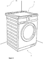
Figure 1 shows a perspective view of two appliances which are connected by a coupling structure; -
Figure 2 shows a perspective view of the coupling structure, a foot of the first appliance, a connecting device and a fixing member; -
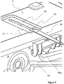
Figure 3 shows the coupling structure arranged on top of the second appliance; -
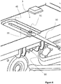
Figures 4 ,5 ,6 show an embodiment of the mounting process of the connecting device to the coupling structure; -
Figures 7 ,8 show an example of the attachment of the connecting device to a holding element. - In
Figure 1 afirst appliance 1, which is a dryer in the present embodiment, and asecond appliance 2, which is a washing machine in the present embodiment, are shown. Thefirst appliance 1, i.e. the dryer, has to be arranged onto thesecond appliance 2 in a stable manner. For doing so, acoupling structure 3 is employed. - In other embodiments not illustrated, the
first appliance 1 can be arranged on top of a supporting pedestal, for example a piece of furniture. The piece of furniture may be for example a box adapted to contain garments or laundry treatment products. - Each of the appliances, 1 and 2, comprises a cabinet, 1a and 2a, preferably parallepiped-shaped. Said cabinet has a plurality of walls, preferably a front wall, two lateral walls, a rear wall and a top wall (1b, 1c, 1d, 1e, 1f).
- The upper appliance, i.e. the
first appliance 1, has four feet (one of them being schematically shown inFigure 2 with reference 7) which are arranged at stems 8 inFigure 2 which often are designed as a threaded rod. - In
Figure 2 it can be seen that thecoupling structure 3 has aframe element 4. Theframe element 4 has a substantial U-shaped form. So, a receiving space is formed for amovable shelf 25. Themovable shelf 25 is preferably a panel element which can be extracted/inserted from/into the coupling structure the coupling structure. Themovable shelf 25 preferably comprises ahandle 26. Themovable shelf 25 can be for example used as a support for garments or laundry treatment products during preparation of laundry and/or the appliances for carrying out a laundry treatment process. In other embodiments themovable shelf 25 can be replaced by a drawer. In other embodiments both a drawer and a shelf can be implemented. - The
coupling structure 3 comprises aseat 40 which has preferably an elongated shape. - The
coupling structure 3 has fourcoupling elements coupling elements front feet 7 of thefirst appliance 1 and twocoupling elements rear feet 7 of thefirst appliance 1. - Preferably, the
coupling structure 3 comprisesadapter elements 17. A more detailed description of this type of adapter elements is provided in the applicationEP 2703536 A1 of the same Applicant to which the present description refers to. - The
coupling structure 3 comprises a connectingdevice 30. The connectingdevice 30 has a shape that is elongated in one direction, afirst end 31 and asecond end 32. - The
first end 31 is adapted to be connected to thecoupling structure 3, preferably to theseat 40, which is adapted to receive thefirst end 31 of the connectingdevice 30 or a fixingmember 51 that connects the connectingdevice 30 to thecoupling structure 3, in a plurality of positions. Preferably, the fixingmember 51 is a threaded element, for example a screw or a bolt. - In an embodiment not illustrated the coupling structure is integrated or forms an integral part of one
wall cabinet 1a. Preferably, thecoupling structure 3 is integrated or forms an integral part of thebase wall 1g of thecabinet 1a of thefirst appliance 1. Alternatively, with reference to thesecond appliance 2, thecoupling structure 3 may be integrated or forming an integral part of its top wall. - The
second end 32 is provided with an attachingmember 100 so that the connecting device is attached to a holdingelement 70 available in the location where the appliance has to be placed. - In the embodiment illustrated in
Figure 7 , the attachingmember 100 is ascrew 60 and anexpandable member 80 that receives thescrew 60 therein and is provided to be received in a hole drilled in the holdingelement 70. Thescrew 60 is adapted to engage thesecond end 32 of the connectingdevice 30, which remains free after the first end has been connected to thecoupling structure 3, and attach it to the holdingelement 70. The attachingmember 100 may have different configurations as previously described. - In the example illustrated, the holding
element 70 is a wall available in the location where the appliance has to be placed. In other embodiments, not illustrated, the holdingelement 70 can be, for example, a pillar available in the location where the appliance has to be placed. - The connecting
device 30 is preferably made of a resilient flexible material which elastically deforms when subject to a shearing force and is substantially inextensible when subjected to a traction force acting in a direction parallel to the elongation direction of the elongated shaped connectingdevice 30. Preferably the connectingdevice 30 is made of plastic, i.e. polymeric material. - The connecting
device 30 has at least one aperture (33, 34) at each of its ends (31, 32). Preferably, the apertures are holes or slots. In other embodiments, the apertures may also have different shapes, for example rectangular or oval. - In the embodiment illustrated, the
aperture 33 is a hole while theaperture 34 has a slot shape. Thehole 33 of thefirst end 31 is adapted to be coupled to thecoupling structure 3. Theslot 34 of thesecond end 32 is adapted to be attached to the holdingelement 70 available in a location where the appliance has to be placed. - In some embodiments not illustrated the connecting
device 30 has a plurality of holes distributed in his length. Said holes have the function of allowing a certain compensation of the distance of thecoupling structure 3 from the holdingelement 70 available in the location where the appliance has to be placed. Preferably, the holes are distributed at the same distance one another along the elongation direction of the elongated shaped connecting device.. - With reference to
Figures 3 to 8 different steps of a method for arranging theappliance 1 on top of acoupling structure 3, in particular, the following steps are disclosed: - a) coupling the
first appliance 1 to thecoupling structure 3 by means of the one ormore coupling elements - b) providing a connection between the
first end 31 of the connectingdevice 30 and thecoupling structure 3; - c) providing a holding
element 70 in a location where thefirst appliance 1 has to be placed; - d) attaching the connecting
device 30 to the holdingelement 70 by means of an attachingmember 100; - e) providing a
second appliance 2; - f) arranging the coupling structure on top of the
second appliance 2. - In
Figure 3 the user places thesecond appliance 2 in proximity of the holdingelement 70. The distance from the holdingelement 70 must be close enough to connect the connectingdevice 30 both to thecoupling structure 3 and to the holdingelement 70. The user arranges thecoupling structure 3 on top of thesecond appliance 2. In other embodiments not illustrated, thecoupling structure 3, instead of on top of asecond appliance 2, can be placed on top of a supporting pedestal, for example a piece of furniture. - In
Figure 4 ,5 ,6 , the user connects thefirst end 31 of the connectingdevice 30 to thecoupling structure 3. Preferably the connecting device is connected to thecoupling structure 3 through a fixing member (seereference numeral 51 inFigure 5 ). Preferably the coupling structure also comprises a hooking member (seereference numeral 50 inFigure 4 ). Preferably the hookingmember 50 comprises ahole 50a which is adapted to receive the fixingmember 51, so that the connectingdevice 30 can be fixed on theseat 40 of thecoupling structure 30. However other connections are possible between thefirst end 31 of the connectingdevice 30 and thecoupling structure 3. - In
Figure 7 ,8 , the user attaches the connectingdevice 30 to the holdingmember 70 by means of the attachingmember 100. The user uses the attachingmember 100 to attach thesecond end 32 of the connectingdevice 30 to the holdingelement 70. However other possible coupling solutions can be used. - The user can couple the
first appliance 1 to thecoupling structure 3 by means of one ormore coupling elements coupling elements coupling structure 3 are connected to thefeet 7 of thefirst appliance 1. - The final configuration is the one illustrated in
Figure 1 . - Preferably, step a) is carried out after steps b), d) are completed. Steps b) can be carried out before step d) or vice versa.
- In one embodiment the user first connects the
first end 31 of the connecting thedevice 30 to thecoupling structure 3 and then the second 32 end of the connectingdevice 30 to the holdingelement 70 using an attachingmember 100. In another embodiment the user can attach thesecond end 32 to the holdingelement 70 before connecting thefirst end 31 to thecoupling structure 3. - Step a) is preferably made after b) or d) so as to facilitate the user in the connection of the connecting
device 30 to thecoupling structure 3.
Claims (15)
- A coupling structure (3) for receiving a laundry treatment appliance (1) thereon, said coupling structure (3) comprising one or more coupling elements (5, 6, 10, 11) to be coupled to the appliance (1), characterized by comprising a connecting device (30) having a shape elongated in one direction which has a first end (31) connected or adapted to be connected to said coupling structure (3) and a second end (32) provided with an attaching member (100) for attaching said connecting device (30) to a holding element (70) available in a location where the appliance (1) has to be placed, such that a movement of the appliance (1) increasing the distance between the holding element (70) and the coupling structure (3) attached thereto is prevented.
- A coupling structure (3) according to claim 1 comprising a seat (40) for receiving the first end (31) of the connecting device (30) or for receiving a fixing member (51) that connects the connecting device (30) to the coupling structure (3).
- A coupling structure (3) according to claim 1 or 2 wherein the coupling structure (3) comprises a frame element (4) which is designed to be fixed on top of a second appliance (2) or on a supporting pedestal to raise the coupling structure (3) at a predetermined height, such that the second appliance (2) or the supporting pedestal is arranged below said appliance (1) with the coupling structure (3) therebetween.
- A coupling structure (3) according to any of the preceding claims comprising a movable shelf (25) and/or a drawer.
- A coupling structure (3) according to any of the preceding claims wherein the position of said first end (31) of the connecting device (30) is adjustable in a plurality of positions relative to the coupling structure (3).
- A coupling structure (3) according to any of the preceding claims wherein the connecting device (30) is slidably and/or rotatably coupled to the coupling structure (3).
- A coupling structure (3) according to any of the preceding claims wherein the connecting device (30) is made of a resilient flexible material which elastically deforms when subject to a shearing force and is substantially inextensible when subjected to a traction force acting in a direction parallel to the elongation direction of the elongated shaped connecting device (30).
- A coupling structure (3) according to any of the preceding claims wherein the connecting device (30) comprises a plurality of holes or slots (33, 34) and having at least one hole or slot at each end (31,32).
- A coupling structure (3) according to any of the preceding claims wherein the attaching member (100) comprises, a nail or a threaded element (60) with a nut or an expandable member (80).
- Method for arranging a laundry treatment appliance (1) on top of a coupling structure (3) wherein the method comprises:a) coupling the appliance (1) to the coupling structure (3) by means of the one or more coupling elements (5, 6, 10, 11);b) providing a connection between the first end (31) of the connecting device (30) and the coupling structure (3);c) providing a holding element (70) in a location where the appliance (1) has to be placed;d) attaching the connecting device (30) to the holding element (70) by means of an attaching member (100).
- Method according to claim 10 further comprising:e) providing a second appliance (2) or a supporting pedestal;f) arranging the coupling structure (3) on top of the second appliance (2) or the supporting pedestal.
- Method according to claim 11 wherein steps c), e), f) are carried out before steps b), d).
- Method according to any claim 10 to 12 wherein step a) is carried out after steps b), d) are completed.
- A laundry treatment appliance (1) comprising a cabinet (1a) having a plurality of walls (1b, 1c, 1d, 1e, 1f) and a coupling structure (3) according to any claim 1 to 8 characterized in that said coupling structure (3) is integrated or forms an integral part of one wall (1b, 1c, 1d, 1e, 1f) of the cabinet (1a).
- A laundry treatment appliance (1) according to claim 14 where the position the connecting device (30) can be regulated in a direction perpendicular to the holding member (70).
Priority Applications (3)
| Application Number | Priority Date | Filing Date | Title |
|---|---|---|---|
| EP18215375.9A EP3670727B1 (en) | 2018-12-21 | 2018-12-21 | Coupling structure for laundry treatment appliances |
| AU2019279934A AU2019279934B2 (en) | 2018-12-21 | 2019-12-10 | Coupling structure for a laundry treatment appliance |
| CN201911317540.1A CN111350051B (en) | 2018-12-21 | 2019-12-19 | Coupling structure for laundry treating apparatus |
Applications Claiming Priority (1)
| Application Number | Priority Date | Filing Date | Title |
|---|---|---|---|
| EP18215375.9A EP3670727B1 (en) | 2018-12-21 | 2018-12-21 | Coupling structure for laundry treatment appliances |
Publications (2)
| Publication Number | Publication Date |
|---|---|
| EP3670727A1 true EP3670727A1 (en) | 2020-06-24 |
| EP3670727B1 EP3670727B1 (en) | 2023-10-04 |
Family
ID=64900784
Family Applications (1)
| Application Number | Title | Priority Date | Filing Date |
|---|---|---|---|
| EP18215375.9A Active EP3670727B1 (en) | 2018-12-21 | 2018-12-21 | Coupling structure for laundry treatment appliances |
Country Status (3)
| Country | Link |
|---|---|
| EP (1) | EP3670727B1 (en) |
| CN (1) | CN111350051B (en) |
| AU (1) | AU2019279934B2 (en) |
Cited By (5)
| Publication number | Priority date | Publication date | Assignee | Title |
|---|---|---|---|---|
| WO2022228172A1 (en) * | 2021-04-29 | 2022-11-03 | 青岛海尔滚筒洗衣机有限公司 | Stacked clothes treatment device |
| WO2023020066A1 (en) * | 2021-08-20 | 2023-02-23 | 合肥美的洗衣机有限公司 | Connection frame, clothing treatment device and clothing treatment apparatus |
| WO2024072346A1 (en) * | 2022-09-27 | 2024-04-04 | Arcelik Anonim Sirketi | A stacking apparatus |
| WO2024080955A1 (en) * | 2022-10-10 | 2024-04-18 | Vestel Beyaz Esya Sanayi Ve Ticaret Anonim Sirketi | A connecting apparatus |
| EP4524315A4 (en) * | 2022-11-22 | 2025-09-24 | Samsung Electronics Co Ltd | CLOTHING TREATMENT SYSTEM |
Families Citing this family (2)
| Publication number | Priority date | Publication date | Assignee | Title |
|---|---|---|---|---|
| CN114059319B (en) * | 2020-07-29 | 2023-11-03 | 无锡小天鹅电器有限公司 | Combined equipment and base mechanism |
| CN115897169A (en) * | 2021-08-20 | 2023-04-04 | 无锡小天鹅电器有限公司 | Connecting frame, clothes treating device and clothes treating equipment |
Citations (6)
| Publication number | Priority date | Publication date | Assignee | Title |
|---|---|---|---|---|
| EP1550756A1 (en) * | 2003-12-29 | 2005-07-06 | Lg Electronics Inc. | Assembly for stacking washers and dryers |
| DE102005026134A1 (en) | 2005-06-06 | 2006-12-07 | BSH Bosch und Siemens Hausgeräte GmbH | Connection for domestic units, comprises a frame or board which can be fixed to the lower unit, and shoe sections for fixing the upper unit feet |
| EP2436820A1 (en) * | 2010-10-04 | 2012-04-04 | Electrolux Home Products Corporation N.V. | Device for connecting a first appliance with a second appliance |
| EP2703536A1 (en) | 2012-08-31 | 2014-03-05 | Electrolux Home Products Corporation N.V. | Device for connecting a first appliance with a second appliance |
| WO2014101963A1 (en) * | 2012-12-30 | 2014-07-03 | Arcelik Anonim Sirketi | Laundry treatment appliance stacking apparatus |
| WO2017003167A1 (en) * | 2015-06-30 | 2017-01-05 | Lg Electronics Inc. | Laundry treating apparatus |
Family Cites Families (20)
| Publication number | Priority date | Publication date | Assignee | Title |
|---|---|---|---|---|
| DE3827789A1 (en) * | 1988-08-16 | 1990-02-22 | Bosch Siemens Hausgeraete | DEVICE FOR TIP-SAFE CONNECTING TWO STRESSED HOUSEHOLD MACHINES |
| DE10109744C2 (en) * | 2000-03-15 | 2003-08-21 | Miele & Cie | exhaust dryer |
| JP2002011296A (en) * | 2000-06-30 | 2002-01-15 | Sanyo Electric Co Ltd | Support base for clothes dryer |
| JP3977333B2 (en) * | 2002-01-09 | 2007-09-19 | エルジー エレクトロニクス インコーポレーテッド | Washing machine and dryer door and washing machine and dryer including the same |
| US7240889B2 (en) * | 2003-12-10 | 2007-07-10 | Thomas Giovinazzi | Securing bracket for a floor supported laundry appliance |
| KR100747567B1 (en) * | 2004-12-30 | 2007-08-08 | 엘지전자 주식회사 | structure of wall decoration in washing device |
| KR100841308B1 (en) * | 2005-04-22 | 2008-06-25 | 엘지전자 주식회사 | Laundry device |
| KR101430456B1 (en) * | 2007-11-12 | 2014-08-18 | 엘지전자 주식회사 | Ancillary clothing processing equipment |
| JP4603063B2 (en) * | 2008-07-04 | 2010-12-22 | パナソニック株式会社 | Drum type washer / dryer |
| EP2415919B1 (en) * | 2010-08-06 | 2014-03-05 | Electrolux Home Products Corporation N.V. | Operating method of a laundry washing machine and laundry washing machine implementing such method |
| EP2436819B1 (en) * | 2010-10-04 | 2014-03-19 | Electrolux Home Products Corporation N.V. | Device for connecting a first appliance with a second appliance |
| WO2012062673A1 (en) * | 2010-11-12 | 2012-05-18 | Arcelik Anonim Sirketi | A washer/dryer comprising a connection member |
| ITTO20130277A1 (en) * | 2013-04-05 | 2014-10-06 | Indesit Co Spa | DEVICE FOR FIXING BAPTISCOPES TO HOUSEHOLD APPLIANCES |
| PL2837723T3 (en) * | 2013-08-13 | 2022-02-07 | Electrolux Appliances Aktiebolag | Laundry washing and drying machine |
| EP2837733B1 (en) * | 2013-08-13 | 2017-04-12 | Electrolux Appliances Aktiebolag | Laundry treatment device including a control-panel assembly |
| EP2851622B1 (en) * | 2013-09-19 | 2019-01-16 | Electrolux Appliances Aktiebolag | A holding structure for a first sheet-like element and method of assembling thereof |
| KR102487097B1 (en) * | 2014-05-30 | 2023-01-11 | 엘지전자 주식회사 | Laundry Treating Apparatus |
| KR102486960B1 (en) * | 2015-06-30 | 2023-01-11 | 엘지전자 주식회사 | Laundry Treating Apparatus |
| CN108203870B (en) * | 2016-12-16 | 2021-06-01 | 合肥海尔洗衣机有限公司 | Washing machine tray parts and washing machine |
| CN107338613B (en) * | 2017-06-26 | 2019-09-17 | 无锡小天鹅电器有限公司 | Stack mounting structure and the device for clothing processing with it |
-
2018
- 2018-12-21 EP EP18215375.9A patent/EP3670727B1/en active Active
-
2019
- 2019-12-10 AU AU2019279934A patent/AU2019279934B2/en active Active
- 2019-12-19 CN CN201911317540.1A patent/CN111350051B/en active Active
Patent Citations (6)
| Publication number | Priority date | Publication date | Assignee | Title |
|---|---|---|---|---|
| EP1550756A1 (en) * | 2003-12-29 | 2005-07-06 | Lg Electronics Inc. | Assembly for stacking washers and dryers |
| DE102005026134A1 (en) | 2005-06-06 | 2006-12-07 | BSH Bosch und Siemens Hausgeräte GmbH | Connection for domestic units, comprises a frame or board which can be fixed to the lower unit, and shoe sections for fixing the upper unit feet |
| EP2436820A1 (en) * | 2010-10-04 | 2012-04-04 | Electrolux Home Products Corporation N.V. | Device for connecting a first appliance with a second appliance |
| EP2703536A1 (en) | 2012-08-31 | 2014-03-05 | Electrolux Home Products Corporation N.V. | Device for connecting a first appliance with a second appliance |
| WO2014101963A1 (en) * | 2012-12-30 | 2014-07-03 | Arcelik Anonim Sirketi | Laundry treatment appliance stacking apparatus |
| WO2017003167A1 (en) * | 2015-06-30 | 2017-01-05 | Lg Electronics Inc. | Laundry treating apparatus |
Cited By (5)
| Publication number | Priority date | Publication date | Assignee | Title |
|---|---|---|---|---|
| WO2022228172A1 (en) * | 2021-04-29 | 2022-11-03 | 青岛海尔滚筒洗衣机有限公司 | Stacked clothes treatment device |
| WO2023020066A1 (en) * | 2021-08-20 | 2023-02-23 | 合肥美的洗衣机有限公司 | Connection frame, clothing treatment device and clothing treatment apparatus |
| WO2024072346A1 (en) * | 2022-09-27 | 2024-04-04 | Arcelik Anonim Sirketi | A stacking apparatus |
| WO2024080955A1 (en) * | 2022-10-10 | 2024-04-18 | Vestel Beyaz Esya Sanayi Ve Ticaret Anonim Sirketi | A connecting apparatus |
| EP4524315A4 (en) * | 2022-11-22 | 2025-09-24 | Samsung Electronics Co Ltd | CLOTHING TREATMENT SYSTEM |
Also Published As
| Publication number | Publication date |
|---|---|
| CN111350051B (en) | 2024-01-09 |
| AU2019279934B2 (en) | 2025-08-14 |
| EP3670727B1 (en) | 2023-10-04 |
| CN111350051A (en) | 2020-06-30 |
| AU2019279934A1 (en) | 2020-07-09 |
Similar Documents
| Publication | Publication Date | Title |
|---|---|---|
| EP3670727B1 (en) | Coupling structure for laundry treatment appliances | |
| US6915913B2 (en) | Attachment device for shelving and organizer systems | |
| US4928833A (en) | Storage organizer system and means for installing the same | |
| US20120273636A1 (en) | Hanger holder accessory and system | |
| AU2013243243B2 (en) | Device for supporting domestic appliances | |
| EP1159893A2 (en) | Clothes drying, dewrinkling and ironing cabinet | |
| EP2436820B1 (en) | Device for connecting a first appliance with a second appliance | |
| KR20060109973A (en) | Hanging device | |
| KR100904635B1 (en) | A towel ledge | |
| KR101818835B1 (en) | Shelf for Dishes | |
| KR101551605B1 (en) | clothes hanger for door | |
| KR100431249B1 (en) | Bar Shelf With A Extension Function Combined Use Tableware Dryer | |
| KR101804754B1 (en) | Extractable closet tweeser | |
| KR100958061B1 (en) | A towel ledge | |
| KR0125048Y1 (en) | A shelf attached to a sink | |
| CN109938505A (en) | washing machine rack | |
| KR102445695B1 (en) | clothes hanger type drying rack | |
| KR200355552Y1 (en) | dress room | |
| KR19990035802U (en) | Post telescopic adjuster | |
| KR20180002776U (en) | Hanger for hydrnat | |
| KR20120002122U (en) | Apparatus for fixing of shelf | |
| KR0133260Y1 (en) | Washing machine cabinet structure | |
| KR102380373B1 (en) | Kitchen shelf | |
| KR100997389B1 (en) | Hanger Shelf | |
| KR101021586B1 (en) | Detachable Shelf for Furniture |
Legal Events
| Date | Code | Title | Description |
|---|---|---|---|
| PUAI | Public reference made under article 153(3) epc to a published international application that has entered the european phase |
Free format text: ORIGINAL CODE: 0009012 |
|
| STAA | Information on the status of an ep patent application or granted ep patent |
Free format text: STATUS: THE APPLICATION HAS BEEN PUBLISHED |
|
| AK | Designated contracting states |
Kind code of ref document: A1 Designated state(s): AL AT BE BG CH CY CZ DE DK EE ES FI FR GB GR HR HU IE IS IT LI LT LU LV MC MK MT NL NO PL PT RO RS SE SI SK SM TR |
|
| AX | Request for extension of the european patent |
Extension state: BA ME |
|
| STAA | Information on the status of an ep patent application or granted ep patent |
Free format text: STATUS: REQUEST FOR EXAMINATION WAS MADE |
|
| 17P | Request for examination filed |
Effective date: 20210111 |
|
| RBV | Designated contracting states (corrected) |
Designated state(s): AL AT BE BG CH CY CZ DE DK EE ES FI FR GB GR HR HU IE IS IT LI LT LU LV MC MK MT NL NO PL PT RO RS SE SI SK SM TR |
|
| STAA | Information on the status of an ep patent application or granted ep patent |
Free format text: STATUS: EXAMINATION IS IN PROGRESS |
|
| 17Q | First examination report despatched |
Effective date: 20220519 |
|
| GRAP | Despatch of communication of intention to grant a patent |
Free format text: ORIGINAL CODE: EPIDOSNIGR1 |
|
| STAA | Information on the status of an ep patent application or granted ep patent |
Free format text: STATUS: GRANT OF PATENT IS INTENDED |
|
| INTG | Intention to grant announced |
Effective date: 20230515 |
|
| GRAS | Grant fee paid |
Free format text: ORIGINAL CODE: EPIDOSNIGR3 |
|
| GRAA | (expected) grant |
Free format text: ORIGINAL CODE: 0009210 |
|
| STAA | Information on the status of an ep patent application or granted ep patent |
Free format text: STATUS: THE PATENT HAS BEEN GRANTED |
|
| AK | Designated contracting states |
Kind code of ref document: B1 Designated state(s): AL AT BE BG CH CY CZ DE DK EE ES FI FR GB GR HR HU IE IS IT LI LT LU LV MC MK MT NL NO PL PT RO RS SE SI SK SM TR |
|
| REG | Reference to a national code |
Ref country code: GB Ref legal event code: FG4D |
|
| P01 | Opt-out of the competence of the unified patent court (upc) registered |
Effective date: 20230901 |
|
| REG | Reference to a national code |
Ref country code: CH Ref legal event code: EP |
|
| REG | Reference to a national code |
Ref country code: IE Ref legal event code: FG4D |
|
| REG | Reference to a national code |
Ref country code: DE Ref legal event code: R096 Ref document number: 602018058590 Country of ref document: DE |
|
| REG | Reference to a national code |
Ref country code: LT Ref legal event code: MG9D |
|
| REG | Reference to a national code |
Ref country code: NL Ref legal event code: MP Effective date: 20231004 |
|
| REG | Reference to a national code |
Ref country code: AT Ref legal event code: MK05 Ref document number: 1617864 Country of ref document: AT Kind code of ref document: T Effective date: 20231004 |
|
| PG25 | Lapsed in a contracting state [announced via postgrant information from national office to epo] |
Ref country code: NL Free format text: LAPSE BECAUSE OF FAILURE TO SUBMIT A TRANSLATION OF THE DESCRIPTION OR TO PAY THE FEE WITHIN THE PRESCRIBED TIME-LIMIT Effective date: 20231004 |
|
| PG25 | Lapsed in a contracting state [announced via postgrant information from national office to epo] |
Ref country code: GR Free format text: LAPSE BECAUSE OF FAILURE TO SUBMIT A TRANSLATION OF THE DESCRIPTION OR TO PAY THE FEE WITHIN THE PRESCRIBED TIME-LIMIT Effective date: 20240105 |
|
| PG25 | Lapsed in a contracting state [announced via postgrant information from national office to epo] |
Ref country code: IS Free format text: LAPSE BECAUSE OF FAILURE TO SUBMIT A TRANSLATION OF THE DESCRIPTION OR TO PAY THE FEE WITHIN THE PRESCRIBED TIME-LIMIT Effective date: 20240204 |
|
| PG25 | Lapsed in a contracting state [announced via postgrant information from national office to epo] |
Ref country code: LT Free format text: LAPSE BECAUSE OF FAILURE TO SUBMIT A TRANSLATION OF THE DESCRIPTION OR TO PAY THE FEE WITHIN THE PRESCRIBED TIME-LIMIT Effective date: 20231004 |
|
| PG25 | Lapsed in a contracting state [announced via postgrant information from national office to epo] |
Ref country code: AT Free format text: LAPSE BECAUSE OF FAILURE TO SUBMIT A TRANSLATION OF THE DESCRIPTION OR TO PAY THE FEE WITHIN THE PRESCRIBED TIME-LIMIT Effective date: 20231004 |
|
| PG25 | Lapsed in a contracting state [announced via postgrant information from national office to epo] |
Ref country code: ES Free format text: LAPSE BECAUSE OF FAILURE TO SUBMIT A TRANSLATION OF THE DESCRIPTION OR TO PAY THE FEE WITHIN THE PRESCRIBED TIME-LIMIT Effective date: 20231004 |
|
| PG25 | Lapsed in a contracting state [announced via postgrant information from national office to epo] |
Ref country code: LT Free format text: LAPSE BECAUSE OF FAILURE TO SUBMIT A TRANSLATION OF THE DESCRIPTION OR TO PAY THE FEE WITHIN THE PRESCRIBED TIME-LIMIT Effective date: 20231004 Ref country code: IS Free format text: LAPSE BECAUSE OF FAILURE TO SUBMIT A TRANSLATION OF THE DESCRIPTION OR TO PAY THE FEE WITHIN THE PRESCRIBED TIME-LIMIT Effective date: 20240204 Ref country code: GR Free format text: LAPSE BECAUSE OF FAILURE TO SUBMIT A TRANSLATION OF THE DESCRIPTION OR TO PAY THE FEE WITHIN THE PRESCRIBED TIME-LIMIT Effective date: 20240105 Ref country code: ES Free format text: LAPSE BECAUSE OF FAILURE TO SUBMIT A TRANSLATION OF THE DESCRIPTION OR TO PAY THE FEE WITHIN THE PRESCRIBED TIME-LIMIT Effective date: 20231004 Ref country code: BG Free format text: LAPSE BECAUSE OF FAILURE TO SUBMIT A TRANSLATION OF THE DESCRIPTION OR TO PAY THE FEE WITHIN THE PRESCRIBED TIME-LIMIT Effective date: 20240104 Ref country code: AT Free format text: LAPSE BECAUSE OF FAILURE TO SUBMIT A TRANSLATION OF THE DESCRIPTION OR TO PAY THE FEE WITHIN THE PRESCRIBED TIME-LIMIT Effective date: 20231004 Ref country code: PT Free format text: LAPSE BECAUSE OF FAILURE TO SUBMIT A TRANSLATION OF THE DESCRIPTION OR TO PAY THE FEE WITHIN THE PRESCRIBED TIME-LIMIT Effective date: 20240205 |
|
| PG25 | Lapsed in a contracting state [announced via postgrant information from national office to epo] |
Ref country code: SE Free format text: LAPSE BECAUSE OF FAILURE TO SUBMIT A TRANSLATION OF THE DESCRIPTION OR TO PAY THE FEE WITHIN THE PRESCRIBED TIME-LIMIT Effective date: 20231004 Ref country code: RS Free format text: LAPSE BECAUSE OF FAILURE TO SUBMIT A TRANSLATION OF THE DESCRIPTION OR TO PAY THE FEE WITHIN THE PRESCRIBED TIME-LIMIT Effective date: 20231004 Ref country code: PL Free format text: LAPSE BECAUSE OF FAILURE TO SUBMIT A TRANSLATION OF THE DESCRIPTION OR TO PAY THE FEE WITHIN THE PRESCRIBED TIME-LIMIT Effective date: 20231004 Ref country code: NO Free format text: LAPSE BECAUSE OF FAILURE TO SUBMIT A TRANSLATION OF THE DESCRIPTION OR TO PAY THE FEE WITHIN THE PRESCRIBED TIME-LIMIT Effective date: 20240104 Ref country code: LV Free format text: LAPSE BECAUSE OF FAILURE TO SUBMIT A TRANSLATION OF THE DESCRIPTION OR TO PAY THE FEE WITHIN THE PRESCRIBED TIME-LIMIT Effective date: 20231004 Ref country code: HR Free format text: LAPSE BECAUSE OF FAILURE TO SUBMIT A TRANSLATION OF THE DESCRIPTION OR TO PAY THE FEE WITHIN THE PRESCRIBED TIME-LIMIT Effective date: 20231004 |
|
| REG | Reference to a national code |
Ref country code: DE Ref legal event code: R097 Ref document number: 602018058590 Country of ref document: DE |
|
| PG25 | Lapsed in a contracting state [announced via postgrant information from national office to epo] |
Ref country code: DK Free format text: LAPSE BECAUSE OF FAILURE TO SUBMIT A TRANSLATION OF THE DESCRIPTION OR TO PAY THE FEE WITHIN THE PRESCRIBED TIME-LIMIT Effective date: 20231004 |
|
| PG25 | Lapsed in a contracting state [announced via postgrant information from national office to epo] |
Ref country code: CZ Free format text: LAPSE BECAUSE OF FAILURE TO SUBMIT A TRANSLATION OF THE DESCRIPTION OR TO PAY THE FEE WITHIN THE PRESCRIBED TIME-LIMIT Effective date: 20231004 |
|
| PG25 | Lapsed in a contracting state [announced via postgrant information from national office to epo] |
Ref country code: SK Free format text: LAPSE BECAUSE OF FAILURE TO SUBMIT A TRANSLATION OF THE DESCRIPTION OR TO PAY THE FEE WITHIN THE PRESCRIBED TIME-LIMIT Effective date: 20231004 |
|
| PG25 | Lapsed in a contracting state [announced via postgrant information from national office to epo] |
Ref country code: SM Free format text: LAPSE BECAUSE OF FAILURE TO SUBMIT A TRANSLATION OF THE DESCRIPTION OR TO PAY THE FEE WITHIN THE PRESCRIBED TIME-LIMIT Effective date: 20231004 Ref country code: SK Free format text: LAPSE BECAUSE OF FAILURE TO SUBMIT A TRANSLATION OF THE DESCRIPTION OR TO PAY THE FEE WITHIN THE PRESCRIBED TIME-LIMIT Effective date: 20231004 Ref country code: RO Free format text: LAPSE BECAUSE OF FAILURE TO SUBMIT A TRANSLATION OF THE DESCRIPTION OR TO PAY THE FEE WITHIN THE PRESCRIBED TIME-LIMIT Effective date: 20231004 Ref country code: IT Free format text: LAPSE BECAUSE OF FAILURE TO SUBMIT A TRANSLATION OF THE DESCRIPTION OR TO PAY THE FEE WITHIN THE PRESCRIBED TIME-LIMIT Effective date: 20231004 Ref country code: EE Free format text: LAPSE BECAUSE OF FAILURE TO SUBMIT A TRANSLATION OF THE DESCRIPTION OR TO PAY THE FEE WITHIN THE PRESCRIBED TIME-LIMIT Effective date: 20231004 Ref country code: DK Free format text: LAPSE BECAUSE OF FAILURE TO SUBMIT A TRANSLATION OF THE DESCRIPTION OR TO PAY THE FEE WITHIN THE PRESCRIBED TIME-LIMIT Effective date: 20231004 Ref country code: CZ Free format text: LAPSE BECAUSE OF FAILURE TO SUBMIT A TRANSLATION OF THE DESCRIPTION OR TO PAY THE FEE WITHIN THE PRESCRIBED TIME-LIMIT Effective date: 20231004 |
|
| REG | Reference to a national code |
Ref country code: CH Ref legal event code: PL |
|
| PLBE | No opposition filed within time limit |
Free format text: ORIGINAL CODE: 0009261 |
|
| STAA | Information on the status of an ep patent application or granted ep patent |
Free format text: STATUS: NO OPPOSITION FILED WITHIN TIME LIMIT |
|
| PG25 | Lapsed in a contracting state [announced via postgrant information from national office to epo] |
Ref country code: LU Free format text: LAPSE BECAUSE OF NON-PAYMENT OF DUE FEES Effective date: 20231221 |
|
| PG25 | Lapsed in a contracting state [announced via postgrant information from national office to epo] |
Ref country code: MC Free format text: LAPSE BECAUSE OF FAILURE TO SUBMIT A TRANSLATION OF THE DESCRIPTION OR TO PAY THE FEE WITHIN THE PRESCRIBED TIME-LIMIT Effective date: 20231004 |
|
| REG | Reference to a national code |
Ref country code: BE Ref legal event code: MM Effective date: 20231231 |
|
| PG25 | Lapsed in a contracting state [announced via postgrant information from national office to epo] |
Ref country code: MC Free format text: LAPSE BECAUSE OF FAILURE TO SUBMIT A TRANSLATION OF THE DESCRIPTION OR TO PAY THE FEE WITHIN THE PRESCRIBED TIME-LIMIT Effective date: 20231004 Ref country code: LU Free format text: LAPSE BECAUSE OF NON-PAYMENT OF DUE FEES Effective date: 20231221 |
|
| 26N | No opposition filed |
Effective date: 20240705 |
|
| REG | Reference to a national code |
Ref country code: IE Ref legal event code: MM4A |
|
| PG25 | Lapsed in a contracting state [announced via postgrant information from national office to epo] |
Ref country code: IE Free format text: LAPSE BECAUSE OF NON-PAYMENT OF DUE FEES Effective date: 20231221 |
|
| PG25 | Lapsed in a contracting state [announced via postgrant information from national office to epo] |
Ref country code: BE Free format text: LAPSE BECAUSE OF NON-PAYMENT OF DUE FEES Effective date: 20231231 |
|
| PG25 | Lapsed in a contracting state [announced via postgrant information from national office to epo] |
Ref country code: CH Free format text: LAPSE BECAUSE OF NON-PAYMENT OF DUE FEES Effective date: 20231231 |
|
| PG25 | Lapsed in a contracting state [announced via postgrant information from national office to epo] |
Ref country code: SI Free format text: LAPSE BECAUSE OF FAILURE TO SUBMIT A TRANSLATION OF THE DESCRIPTION OR TO PAY THE FEE WITHIN THE PRESCRIBED TIME-LIMIT Effective date: 20231004 |
|
| PG25 | Lapsed in a contracting state [announced via postgrant information from national office to epo] |
Ref country code: SI Free format text: LAPSE BECAUSE OF FAILURE TO SUBMIT A TRANSLATION OF THE DESCRIPTION OR TO PAY THE FEE WITHIN THE PRESCRIBED TIME-LIMIT Effective date: 20231004 Ref country code: IE Free format text: LAPSE BECAUSE OF NON-PAYMENT OF DUE FEES Effective date: 20231221 Ref country code: CH Free format text: LAPSE BECAUSE OF NON-PAYMENT OF DUE FEES Effective date: 20231231 Ref country code: BE Free format text: LAPSE BECAUSE OF NON-PAYMENT OF DUE FEES Effective date: 20231231 |
|
| PG25 | Lapsed in a contracting state [announced via postgrant information from national office to epo] |
Ref country code: FI Free format text: LAPSE BECAUSE OF FAILURE TO SUBMIT A TRANSLATION OF THE DESCRIPTION OR TO PAY THE FEE WITHIN THE PRESCRIBED TIME-LIMIT Effective date: 20231004 |
|
| PG25 | Lapsed in a contracting state [announced via postgrant information from national office to epo] |
Ref country code: CY Free format text: LAPSE BECAUSE OF FAILURE TO SUBMIT A TRANSLATION OF THE DESCRIPTION OR TO PAY THE FEE WITHIN THE PRESCRIBED TIME-LIMIT; INVALID AB INITIO Effective date: 20181221 |
|
| PG25 | Lapsed in a contracting state [announced via postgrant information from national office to epo] |
Ref country code: HU Free format text: LAPSE BECAUSE OF FAILURE TO SUBMIT A TRANSLATION OF THE DESCRIPTION OR TO PAY THE FEE WITHIN THE PRESCRIBED TIME-LIMIT; INVALID AB INITIO Effective date: 20181221 |
|
| PG25 | Lapsed in a contracting state [announced via postgrant information from national office to epo] |
Ref country code: TR Free format text: LAPSE BECAUSE OF FAILURE TO SUBMIT A TRANSLATION OF THE DESCRIPTION OR TO PAY THE FEE WITHIN THE PRESCRIBED TIME-LIMIT Effective date: 20231004 |
|
| PGFP | Annual fee paid to national office [announced via postgrant information from national office to epo] |
Ref country code: GB Payment date: 20251223 Year of fee payment: 8 |
|
| PGFP | Annual fee paid to national office [announced via postgrant information from national office to epo] |
Ref country code: FR Payment date: 20251223 Year of fee payment: 8 |
|
| PGFP | Annual fee paid to national office [announced via postgrant information from national office to epo] |
Ref country code: DE Payment date: 20251229 Year of fee payment: 8 |