EP3670479A1 - Environmental barrier coating with mullite bondcoat comprising a non-oxide silicon ceramic - Google Patents
Environmental barrier coating with mullite bondcoat comprising a non-oxide silicon ceramic Download PDFInfo
- Publication number
- EP3670479A1 EP3670479A1 EP19215421.9A EP19215421A EP3670479A1 EP 3670479 A1 EP3670479 A1 EP 3670479A1 EP 19215421 A EP19215421 A EP 19215421A EP 3670479 A1 EP3670479 A1 EP 3670479A1
- Authority
- EP
- European Patent Office
- Prior art keywords
- mullite
- nosc
- phase
- bondcoat
- coated component
- Prior art date
- Legal status (The legal status is an assumption and is not a legal conclusion. Google has not performed a legal analysis and makes no representation as to the accuracy of the status listed.)
- Granted
Links
- KZHJGOXRZJKJNY-UHFFFAOYSA-N dioxosilane;oxo(oxoalumanyloxy)alumane Chemical compound O=[Si]=O.O=[Si]=O.O=[Al]O[Al]=O.O=[Al]O[Al]=O.O=[Al]O[Al]=O KZHJGOXRZJKJNY-UHFFFAOYSA-N 0.000 title claims abstract description 141
- 229910052863 mullite Inorganic materials 0.000 title claims abstract description 141
- 238000000576 coating method Methods 0.000 title claims abstract description 39
- XUIMIQQOPSSXEZ-UHFFFAOYSA-N Silicon Chemical compound [Si] XUIMIQQOPSSXEZ-UHFFFAOYSA-N 0.000 title claims abstract description 37
- 239000010703 silicon Substances 0.000 title claims abstract description 35
- 229910052710 silicon Inorganic materials 0.000 title claims abstract description 35
- 239000011248 coating agent Substances 0.000 title claims abstract description 33
- 230000004888 barrier function Effects 0.000 title claims abstract description 25
- 230000007613 environmental effect Effects 0.000 title claims abstract description 25
- 239000000919 ceramic Substances 0.000 title claims abstract description 21
- 229910010271 silicon carbide Inorganic materials 0.000 claims abstract description 50
- HBMJWWWQQXIZIP-UHFFFAOYSA-N silicon carbide Chemical compound [Si+]#[C-] HBMJWWWQQXIZIP-UHFFFAOYSA-N 0.000 claims abstract description 48
- 239000000758 substrate Substances 0.000 claims abstract description 36
- 239000011153 ceramic matrix composite Substances 0.000 claims abstract description 24
- VYPSYNLAJGMNEJ-UHFFFAOYSA-N Silicium dioxide Chemical compound O=[Si]=O VYPSYNLAJGMNEJ-UHFFFAOYSA-N 0.000 claims description 53
- PNEYBMLMFCGWSK-UHFFFAOYSA-N aluminium oxide Inorganic materials [O-2].[O-2].[O-2].[Al+3].[Al+3] PNEYBMLMFCGWSK-UHFFFAOYSA-N 0.000 claims description 22
- 239000000377 silicon dioxide Substances 0.000 claims description 21
- 238000000034 method Methods 0.000 claims description 15
- 229910052581 Si3N4 Inorganic materials 0.000 claims description 12
- 239000000203 mixture Substances 0.000 claims description 12
- HQVNEWCFYHHQES-UHFFFAOYSA-N silicon nitride Chemical compound N12[Si]34N5[Si]62N3[Si]51N64 HQVNEWCFYHHQES-UHFFFAOYSA-N 0.000 claims description 12
- TWNQGVIAIRXVLR-UHFFFAOYSA-N oxo(oxoalumanyloxy)alumane Chemical compound O=[Al]O[Al]=O TWNQGVIAIRXVLR-UHFFFAOYSA-N 0.000 claims description 4
- 238000004519 manufacturing process Methods 0.000 abstract description 2
- 239000010410 layer Substances 0.000 description 53
- 239000007789 gas Substances 0.000 description 23
- 239000000463 material Substances 0.000 description 17
- 239000011159 matrix material Substances 0.000 description 16
- QVGXLLKOCUKJST-UHFFFAOYSA-N atomic oxygen Chemical compound [O] QVGXLLKOCUKJST-UHFFFAOYSA-N 0.000 description 12
- 239000001301 oxygen Substances 0.000 description 12
- 229910052760 oxygen Inorganic materials 0.000 description 12
- 229910052814 silicon oxide Inorganic materials 0.000 description 10
- 229910052761 rare earth metal Inorganic materials 0.000 description 9
- 230000003647 oxidation Effects 0.000 description 8
- 238000007254 oxidation reaction Methods 0.000 description 8
- 239000000567 combustion gas Substances 0.000 description 7
- 239000000835 fiber Substances 0.000 description 7
- 238000002844 melting Methods 0.000 description 6
- 230000008018 melting Effects 0.000 description 6
- -1 rare earth silicate compounds Chemical class 0.000 description 6
- 238000012360 testing method Methods 0.000 description 6
- GQPLMRYTRLFLPF-UHFFFAOYSA-N Nitrous Oxide Chemical compound [O-][N+]#N GQPLMRYTRLFLPF-UHFFFAOYSA-N 0.000 description 5
- 230000015572 biosynthetic process Effects 0.000 description 5
- 239000007921 spray Substances 0.000 description 5
- 229920002134 Carboxymethyl cellulose Polymers 0.000 description 4
- 235000010948 carboxy methyl cellulose Nutrition 0.000 description 4
- 229920006184 cellulose methylcellulose Polymers 0.000 description 4
- 238000012710 chemistry, manufacturing and control Methods 0.000 description 4
- CJNBYAVZURUTKZ-UHFFFAOYSA-N hafnium(IV) oxide Inorganic materials O=[Hf]=O CJNBYAVZURUTKZ-UHFFFAOYSA-N 0.000 description 4
- 239000012720 thermal barrier coating Substances 0.000 description 4
- 229910001233 yttria-stabilized zirconia Inorganic materials 0.000 description 4
- 229910000323 aluminium silicate Inorganic materials 0.000 description 3
- 238000002485 combustion reaction Methods 0.000 description 3
- 239000002131 composite material Substances 0.000 description 3
- 125000004122 cyclic group Chemical group 0.000 description 3
- 238000010586 diagram Methods 0.000 description 3
- 150000002910 rare earth metals Chemical class 0.000 description 3
- 239000000126 substance Substances 0.000 description 3
- 229910000601 superalloy Inorganic materials 0.000 description 3
- 229920000049 Carbon (fiber) Polymers 0.000 description 2
- UGFAIRIUMAVXCW-UHFFFAOYSA-N Carbon monoxide Chemical class [O+]#[C-] UGFAIRIUMAVXCW-UHFFFAOYSA-N 0.000 description 2
- 241000588731 Hafnia Species 0.000 description 2
- XEEYBQQBJWHFJM-UHFFFAOYSA-N Iron Chemical compound [Fe] XEEYBQQBJWHFJM-UHFFFAOYSA-N 0.000 description 2
- PXHVJJICTQNCMI-UHFFFAOYSA-N Nickel Chemical compound [Ni] PXHVJJICTQNCMI-UHFFFAOYSA-N 0.000 description 2
- MCMNRKCIXSYSNV-UHFFFAOYSA-N Zirconium dioxide Chemical compound O=[Zr]=O MCMNRKCIXSYSNV-UHFFFAOYSA-N 0.000 description 2
- 229910002087 alumina-stabilized zirconia Inorganic materials 0.000 description 2
- 239000004917 carbon fiber Substances 0.000 description 2
- 229910002090 carbon oxide Inorganic materials 0.000 description 2
- 238000009792 diffusion process Methods 0.000 description 2
- 238000012986 modification Methods 0.000 description 2
- 230000004048 modification Effects 0.000 description 2
- 229910052575 non-oxide ceramic Inorganic materials 0.000 description 2
- 239000011225 non-oxide ceramic Substances 0.000 description 2
- 230000035699 permeability Effects 0.000 description 2
- 230000008569 process Effects 0.000 description 2
- 230000001141 propulsive effect Effects 0.000 description 2
- 239000002210 silicon-based material Substances 0.000 description 2
- XLYOFNOQVPJJNP-UHFFFAOYSA-N water Chemical compound O XLYOFNOQVPJJNP-UHFFFAOYSA-N 0.000 description 2
- 229910052684 Cerium Inorganic materials 0.000 description 1
- 229910052692 Dysprosium Inorganic materials 0.000 description 1
- 229910052691 Erbium Inorganic materials 0.000 description 1
- 229910052693 Europium Inorganic materials 0.000 description 1
- 229910052688 Gadolinium Inorganic materials 0.000 description 1
- 208000017975 His bundle tachycardia Diseases 0.000 description 1
- 229910052689 Holmium Inorganic materials 0.000 description 1
- UFHFLCQGNIYNRP-UHFFFAOYSA-N Hydrogen Chemical compound [H][H] UFHFLCQGNIYNRP-UHFFFAOYSA-N 0.000 description 1
- 229910052765 Lutetium Inorganic materials 0.000 description 1
- 229910052779 Neodymium Inorganic materials 0.000 description 1
- 229910052777 Praseodymium Inorganic materials 0.000 description 1
- 229910052773 Promethium Inorganic materials 0.000 description 1
- 229910052772 Samarium Inorganic materials 0.000 description 1
- 239000011184 SiC–SiC matrix composite Substances 0.000 description 1
- 229910052771 Terbium Inorganic materials 0.000 description 1
- 229910052775 Thulium Inorganic materials 0.000 description 1
- 229910052769 Ytterbium Inorganic materials 0.000 description 1
- WOIHABYNKOEWFG-UHFFFAOYSA-N [Sr].[Ba] Chemical compound [Sr].[Ba] WOIHABYNKOEWFG-UHFFFAOYSA-N 0.000 description 1
- 239000001996 bearing alloy Substances 0.000 description 1
- 230000002051 biphasic effect Effects 0.000 description 1
- 239000006227 byproduct Substances 0.000 description 1
- 230000015556 catabolic process Effects 0.000 description 1
- GWXLDORMOJMVQZ-UHFFFAOYSA-N cerium Chemical compound [Ce] GWXLDORMOJMVQZ-UHFFFAOYSA-N 0.000 description 1
- 238000012512 characterization method Methods 0.000 description 1
- 229910052729 chemical element Inorganic materials 0.000 description 1
- 238000006243 chemical reaction Methods 0.000 description 1
- 239000011247 coating layer Substances 0.000 description 1
- 229910017052 cobalt Inorganic materials 0.000 description 1
- 239000010941 cobalt Substances 0.000 description 1
- GUTLYIVDDKVIGB-UHFFFAOYSA-N cobalt atom Chemical compound [Co] GUTLYIVDDKVIGB-UHFFFAOYSA-N 0.000 description 1
- 150000001875 compounds Chemical class 0.000 description 1
- 238000005336 cracking Methods 0.000 description 1
- 238000006731 degradation reaction Methods 0.000 description 1
- 230000032798 delamination Effects 0.000 description 1
- HNPSIPDUKPIQMN-UHFFFAOYSA-N dioxosilane;oxo(oxoalumanyloxy)alumane Chemical compound O=[Si]=O.O=[Al]O[Al]=O HNPSIPDUKPIQMN-UHFFFAOYSA-N 0.000 description 1
- KBQHZAAAGSGFKK-UHFFFAOYSA-N dysprosium atom Chemical compound [Dy] KBQHZAAAGSGFKK-UHFFFAOYSA-N 0.000 description 1
- UYAHIZSMUZPPFV-UHFFFAOYSA-N erbium Chemical compound [Er] UYAHIZSMUZPPFV-UHFFFAOYSA-N 0.000 description 1
- 230000003628 erosive effect Effects 0.000 description 1
- OGPBJKLSAFTDLK-UHFFFAOYSA-N europium atom Chemical compound [Eu] OGPBJKLSAFTDLK-UHFFFAOYSA-N 0.000 description 1
- 238000009472 formulation Methods 0.000 description 1
- 239000000446 fuel Substances 0.000 description 1
- UIWYJDYFSGRHKR-UHFFFAOYSA-N gadolinium atom Chemical compound [Gd] UIWYJDYFSGRHKR-UHFFFAOYSA-N 0.000 description 1
- 229910001195 gallium oxide Inorganic materials 0.000 description 1
- 239000001307 helium Substances 0.000 description 1
- 229910052734 helium Inorganic materials 0.000 description 1
- SWQJXJOGLNCZEY-UHFFFAOYSA-N helium atom Chemical compound [He] SWQJXJOGLNCZEY-UHFFFAOYSA-N 0.000 description 1
- 238000007749 high velocity oxygen fuel spraying Methods 0.000 description 1
- KJZYNXUDTRRSPN-UHFFFAOYSA-N holmium atom Chemical compound [Ho] KJZYNXUDTRRSPN-UHFFFAOYSA-N 0.000 description 1
- 239000001257 hydrogen Substances 0.000 description 1
- 229910052739 hydrogen Inorganic materials 0.000 description 1
- 229910052742 iron Inorganic materials 0.000 description 1
- 229910052746 lanthanum Inorganic materials 0.000 description 1
- FZLIPJUXYLNCLC-UHFFFAOYSA-N lanthanum atom Chemical compound [La] FZLIPJUXYLNCLC-UHFFFAOYSA-N 0.000 description 1
- 239000006194 liquid suspension Substances 0.000 description 1
- OHSVLFRHMCKCQY-UHFFFAOYSA-N lutetium atom Chemical compound [Lu] OHSVLFRHMCKCQY-UHFFFAOYSA-N 0.000 description 1
- 239000000155 melt Substances 0.000 description 1
- 150000001247 metal acetylides Chemical class 0.000 description 1
- VNWKTOKETHGBQD-UHFFFAOYSA-N methane Chemical compound C VNWKTOKETHGBQD-UHFFFAOYSA-N 0.000 description 1
- QEFYFXOXNSNQGX-UHFFFAOYSA-N neodymium atom Chemical compound [Nd] QEFYFXOXNSNQGX-UHFFFAOYSA-N 0.000 description 1
- 229910052759 nickel Inorganic materials 0.000 description 1
- 239000001272 nitrous oxide Substances 0.000 description 1
- 239000002245 particle Substances 0.000 description 1
- 230000037361 pathway Effects 0.000 description 1
- 230000035515 penetration Effects 0.000 description 1
- 230000000737 periodic effect Effects 0.000 description 1
- PUDIUYLPXJFUGB-UHFFFAOYSA-N praseodymium atom Chemical compound [Pr] PUDIUYLPXJFUGB-UHFFFAOYSA-N 0.000 description 1
- 239000000047 product Substances 0.000 description 1
- VQMWBBYLQSCNPO-UHFFFAOYSA-N promethium atom Chemical compound [Pm] VQMWBBYLQSCNPO-UHFFFAOYSA-N 0.000 description 1
- 230000002787 reinforcement Effects 0.000 description 1
- 239000012783 reinforcing fiber Substances 0.000 description 1
- 239000012779 reinforcing material Substances 0.000 description 1
- KZUNJOHGWZRPMI-UHFFFAOYSA-N samarium atom Chemical compound [Sm] KZUNJOHGWZRPMI-UHFFFAOYSA-N 0.000 description 1
- 229910052706 scandium Inorganic materials 0.000 description 1
- SIXSYDAISGFNSX-UHFFFAOYSA-N scandium atom Chemical compound [Sc] SIXSYDAISGFNSX-UHFFFAOYSA-N 0.000 description 1
- 230000035939 shock Effects 0.000 description 1
- RMAQACBXLXPBSY-UHFFFAOYSA-N silicic acid Chemical compound O[Si](O)(O)O RMAQACBXLXPBSY-UHFFFAOYSA-N 0.000 description 1
- 238000005245 sintering Methods 0.000 description 1
- 239000002002 slurry Substances 0.000 description 1
- 238000007581 slurry coating method Methods 0.000 description 1
- 229910002076 stabilized zirconia Inorganic materials 0.000 description 1
- 239000000725 suspension Substances 0.000 description 1
- GZCRRIHWUXGPOV-UHFFFAOYSA-N terbium atom Chemical compound [Tb] GZCRRIHWUXGPOV-UHFFFAOYSA-N 0.000 description 1
- FRNOGLGSGLTDKL-UHFFFAOYSA-N thulium atom Chemical compound [Tm] FRNOGLGSGLTDKL-UHFFFAOYSA-N 0.000 description 1
- NAWDYIZEMPQZHO-UHFFFAOYSA-N ytterbium Chemical compound [Yb] NAWDYIZEMPQZHO-UHFFFAOYSA-N 0.000 description 1
- 229910052727 yttrium Inorganic materials 0.000 description 1
- VWQVUPCCIRVNHF-UHFFFAOYSA-N yttrium atom Chemical compound [Y] VWQVUPCCIRVNHF-UHFFFAOYSA-N 0.000 description 1
Images


Classifications
-
- C—CHEMISTRY; METALLURGY
- C04—CEMENTS; CONCRETE; ARTIFICIAL STONE; CERAMICS; REFRACTORIES
- C04B—LIME, MAGNESIA; SLAG; CEMENTS; COMPOSITIONS THEREOF, e.g. MORTARS, CONCRETE OR LIKE BUILDING MATERIALS; ARTIFICIAL STONE; CERAMICS; REFRACTORIES; TREATMENT OF NATURAL STONE
- C04B41/00—After-treatment of mortars, concrete, artificial stone or ceramics; Treatment of natural stone
- C04B41/45—Coating or impregnating, e.g. injection in masonry, partial coating of green or fired ceramics, organic coating compositions for adhering together two concrete elements
- C04B41/52—Multiple coating or impregnating multiple coating or impregnating with the same composition or with compositions only differing in the concentration of the constituents, is classified as single coating or impregnation
-
- C—CHEMISTRY; METALLURGY
- C04—CEMENTS; CONCRETE; ARTIFICIAL STONE; CERAMICS; REFRACTORIES
- C04B—LIME, MAGNESIA; SLAG; CEMENTS; COMPOSITIONS THEREOF, e.g. MORTARS, CONCRETE OR LIKE BUILDING MATERIALS; ARTIFICIAL STONE; CERAMICS; REFRACTORIES; TREATMENT OF NATURAL STONE
- C04B41/00—After-treatment of mortars, concrete, artificial stone or ceramics; Treatment of natural stone
- C04B41/009—After-treatment of mortars, concrete, artificial stone or ceramics; Treatment of natural stone characterised by the material treated
-
- C—CHEMISTRY; METALLURGY
- C04—CEMENTS; CONCRETE; ARTIFICIAL STONE; CERAMICS; REFRACTORIES
- C04B—LIME, MAGNESIA; SLAG; CEMENTS; COMPOSITIONS THEREOF, e.g. MORTARS, CONCRETE OR LIKE BUILDING MATERIALS; ARTIFICIAL STONE; CERAMICS; REFRACTORIES; TREATMENT OF NATURAL STONE
- C04B41/00—After-treatment of mortars, concrete, artificial stone or ceramics; Treatment of natural stone
- C04B41/45—Coating or impregnating, e.g. injection in masonry, partial coating of green or fired ceramics, organic coating compositions for adhering together two concrete elements
- C04B41/4582—Porous coatings, e.g. coating containing porous fillers
-
- C—CHEMISTRY; METALLURGY
- C04—CEMENTS; CONCRETE; ARTIFICIAL STONE; CERAMICS; REFRACTORIES
- C04B—LIME, MAGNESIA; SLAG; CEMENTS; COMPOSITIONS THEREOF, e.g. MORTARS, CONCRETE OR LIKE BUILDING MATERIALS; ARTIFICIAL STONE; CERAMICS; REFRACTORIES; TREATMENT OF NATURAL STONE
- C04B41/00—After-treatment of mortars, concrete, artificial stone or ceramics; Treatment of natural stone
- C04B41/45—Coating or impregnating, e.g. injection in masonry, partial coating of green or fired ceramics, organic coating compositions for adhering together two concrete elements
- C04B41/50—Coating or impregnating, e.g. injection in masonry, partial coating of green or fired ceramics, organic coating compositions for adhering together two concrete elements with inorganic materials
- C04B41/5024—Silicates
-
- C—CHEMISTRY; METALLURGY
- C04—CEMENTS; CONCRETE; ARTIFICIAL STONE; CERAMICS; REFRACTORIES
- C04B—LIME, MAGNESIA; SLAG; CEMENTS; COMPOSITIONS THEREOF, e.g. MORTARS, CONCRETE OR LIKE BUILDING MATERIALS; ARTIFICIAL STONE; CERAMICS; REFRACTORIES; TREATMENT OF NATURAL STONE
- C04B41/00—After-treatment of mortars, concrete, artificial stone or ceramics; Treatment of natural stone
- C04B41/45—Coating or impregnating, e.g. injection in masonry, partial coating of green or fired ceramics, organic coating compositions for adhering together two concrete elements
- C04B41/50—Coating or impregnating, e.g. injection in masonry, partial coating of green or fired ceramics, organic coating compositions for adhering together two concrete elements with inorganic materials
- C04B41/5053—Coating or impregnating, e.g. injection in masonry, partial coating of green or fired ceramics, organic coating compositions for adhering together two concrete elements with inorganic materials non-oxide ceramics
- C04B41/5057—Carbides
- C04B41/5059—Silicon carbide
-
- C—CHEMISTRY; METALLURGY
- C04—CEMENTS; CONCRETE; ARTIFICIAL STONE; CERAMICS; REFRACTORIES
- C04B—LIME, MAGNESIA; SLAG; CEMENTS; COMPOSITIONS THEREOF, e.g. MORTARS, CONCRETE OR LIKE BUILDING MATERIALS; ARTIFICIAL STONE; CERAMICS; REFRACTORIES; TREATMENT OF NATURAL STONE
- C04B41/00—After-treatment of mortars, concrete, artificial stone or ceramics; Treatment of natural stone
- C04B41/80—After-treatment of mortars, concrete, artificial stone or ceramics; Treatment of natural stone of only ceramics
- C04B41/81—Coating or impregnation
- C04B41/89—Coating or impregnation for obtaining at least two superposed coatings having different compositions
-
- F—MECHANICAL ENGINEERING; LIGHTING; HEATING; WEAPONS; BLASTING
- F01—MACHINES OR ENGINES IN GENERAL; ENGINE PLANTS IN GENERAL; STEAM ENGINES
- F01D—NON-POSITIVE DISPLACEMENT MACHINES OR ENGINES, e.g. STEAM TURBINES
- F01D5/00—Blades; Blade-carrying members; Heating, heat-insulating, cooling or antivibration means on the blades or the members
- F01D5/12—Blades
- F01D5/28—Selecting particular materials; Particular measures relating thereto; Measures against erosion or corrosion
- F01D5/288—Protective coatings for blades
-
- C—CHEMISTRY; METALLURGY
- C04—CEMENTS; CONCRETE; ARTIFICIAL STONE; CERAMICS; REFRACTORIES
- C04B—LIME, MAGNESIA; SLAG; CEMENTS; COMPOSITIONS THEREOF, e.g. MORTARS, CONCRETE OR LIKE BUILDING MATERIALS; ARTIFICIAL STONE; CERAMICS; REFRACTORIES; TREATMENT OF NATURAL STONE
- C04B2103/00—Function or property of ingredients for mortars, concrete or artificial stone
- C04B2103/60—Agents for protection against chemical, physical or biological attack
-
- C—CHEMISTRY; METALLURGY
- C04—CEMENTS; CONCRETE; ARTIFICIAL STONE; CERAMICS; REFRACTORIES
- C04B—LIME, MAGNESIA; SLAG; CEMENTS; COMPOSITIONS THEREOF, e.g. MORTARS, CONCRETE OR LIKE BUILDING MATERIALS; ARTIFICIAL STONE; CERAMICS; REFRACTORIES; TREATMENT OF NATURAL STONE
- C04B2111/00—Mortars, concrete or artificial stone or mixtures to prepare them, characterised by specific function, property or use
- C04B2111/00474—Uses not provided for elsewhere in C04B2111/00
- C04B2111/00482—Coating or impregnation materials
-
- C—CHEMISTRY; METALLURGY
- C04—CEMENTS; CONCRETE; ARTIFICIAL STONE; CERAMICS; REFRACTORIES
- C04B—LIME, MAGNESIA; SLAG; CEMENTS; COMPOSITIONS THEREOF, e.g. MORTARS, CONCRETE OR LIKE BUILDING MATERIALS; ARTIFICIAL STONE; CERAMICS; REFRACTORIES; TREATMENT OF NATURAL STONE
- C04B2111/00—Mortars, concrete or artificial stone or mixtures to prepare them, characterised by specific function, property or use
- C04B2111/20—Resistance against chemical, physical or biological attack
-
- F—MECHANICAL ENGINEERING; LIGHTING; HEATING; WEAPONS; BLASTING
- F05—INDEXING SCHEMES RELATING TO ENGINES OR PUMPS IN VARIOUS SUBCLASSES OF CLASSES F01-F04
- F05D—INDEXING SCHEME FOR ASPECTS RELATING TO NON-POSITIVE-DISPLACEMENT MACHINES OR ENGINES, GAS-TURBINES OR JET-PROPULSION PLANTS
- F05D2230/00—Manufacture
- F05D2230/90—Coating; Surface treatment
-
- Y—GENERAL TAGGING OF NEW TECHNOLOGICAL DEVELOPMENTS; GENERAL TAGGING OF CROSS-SECTIONAL TECHNOLOGIES SPANNING OVER SEVERAL SECTIONS OF THE IPC; TECHNICAL SUBJECTS COVERED BY FORMER USPC CROSS-REFERENCE ART COLLECTIONS [XRACs] AND DIGESTS
- Y02—TECHNOLOGIES OR APPLICATIONS FOR MITIGATION OR ADAPTATION AGAINST CLIMATE CHANGE
- Y02T—CLIMATE CHANGE MITIGATION TECHNOLOGIES RELATED TO TRANSPORTATION
- Y02T50/00—Aeronautics or air transport
- Y02T50/60—Efficient propulsion technologies, e.g. for aircraft
Definitions
- the present invention generally relates to bondcoats for use with environmental barrier coatings on ceramic components, particularly silicon-based ceramic matrix components, along with methods of their formation and use.
- TBCs thermal barrier coatings
- CMC ceramic matrix composite
- SiC silicon carbide
- SiC/SiC composites so called SiC/SiC composites.
- CMC and monolithic ceramic components can be coated with environmental barrier coatings (EBCs) to protect them from the harsh environment of high temperature engine sections. EBCs can provide a dense, hermetic seal against the corrosive gases in the hot combustion environment.
- EBC's environmental barrier coatings
- EBC materials are made out of rare earth silicate compounds. These materials seal out water vapor, preventing it from reaching the silicon oxide scale on the silicon carbide or silicon nitride surface, thereby preventing recession. Such materials cannot prevent oxygen penetration, however, which results in oxidation of the underlying substrate. Oxidation of the substrate yields a passive silicon oxide scale, along with the release of carbonaceous or nitrous oxide gas.
- the carbonaceous (i.e., CO, CO 2 ) or nitrous (i.e., NO, NO 2 , etc.) oxide gases cannot escape out through the dense EBC and thus, blisters form, which can cause spallation of the EBC.
- the use of a silicon bondcoat has been the solution to this blistering problem to date.
- the silicon bondcoat provides a layer that oxidizes (forming a passive silicon oxide layer beneath the EBC) without liberating a gaseous by-product.
- the presence of a silicon bondcoat limits the upper temperature of operation for the EBC because the melting point of silicon metal is relatively low.
- the silicon bondcoat melts at coating temperatures of about 1414 °C, which is the melting point of silicon metal. Above these melting temperatures, the silicon bondcoat may delaminate from the underlying substrate, effectively removing the bondcoat and the EBC thereon. As such, it is desirable to have improved bondcoats in the EBC to achieve a higher operational temperature limit for the EBC.
- the coated component includes a ceramic matrix composite (CMC) substrate comprising silicon carbide and having a surface; a mullite/NOSC bondcoat on the surface of the substrate; and an environmental barrier coating on the mullite/NOSC bondcoat.
- the mullite/NOSC bondcoat comprises a non-oxide silicon ceramic (NOSC) phase contained within a mullite phase, with the mullite/NOSC bondcoat comprising 60% to 95% by volume of the mullite phase, such as 65% to 93% by volume of the mullite phase (e.g., 75% to 90% by volume of the mullite phase).
- NOSC non-oxide silicon ceramic
- the mullite phase includes alumina and silica in a stoichiometric ratio within 10% of 3 to 2, such as about 3 to 2 up to about 3.5 to 2. In other embodiments, the mullite phase includes alumina and silica in a stoichiometric ratio within 10% of 2 to 1, such as about 2 to 1 up to about 2.25 to 1. In particular embodiments, the mullite phase may consists of alumina and silica.
- the NOSC phase may include silicon carbide, silicon nitride, silicon oxycarbide, silicon oxynitride, or a mixture thereof.
- the mullite/NOSC bondcoat may include 5% to 40% by volume NOSC, such as 7% to 35% by volume NOSC (e.g., 10% to 25% by volume NOSC).
- the environmental barrier coating may include a plurality of layers with at least one of the layers of the environmental barrier coating comprises a porous layer, such as a porous layer with interconnected porosity. In another embodiment, all of the layers may have interconnected porosity.
- the porous layer may be adjacent to the mullite/NOSC bondcoat such that the porous layer defines the inner surface of the environmental barrier coating.
- the porous layer may include an aluminum oxide.
- the mullite/NOSC bondcoat may be configured to withstand exposure to operating temperatures of up to 1650 °C.
- a method for forming a coated component.
- the method may include forming a mullite/NOSC bondcoat on a surface of a substrate and forming an environmental barrier coating on the mullite/NOSC bondcoat.
- the mullite/NOSC bondcoat includes a NOSC phase contained within a mullite phase, and the mullite/NOSC bondcoat comprises 60% to 95% by volume of the mullite phase.
- first, second, and third may be used interchangeably to distinguish one component from another and are not intended to signify location or importance of the individual components.
- H hydrogen is represented by its common chemical abbreviation H
- He helium is represented by its common chemical abbreviation He
- RE refers to a rare earth element or a mixture of rare earth elements.
- the " RE” refers to the rare earth elements of scandium (Sc), yttrium (Y), lanthanum (La), cerium (Ce), praseodymium (Pr), neodymium (Nd), promethium (Pm), samarium (Sm), europium (Eu), gadolinium (Gd), terbium (Tb), dysprosium (Dy), holmium (Ho), erbium (Er), thulium (Tm), ytterbium (Yb), lutetium (Lu), or mixtures thereof.
- substantially free means no more than an insignificant trace amount present and encompasses completely free (e.g., 0 molar % up to 0.01 molar %).
- a coated component is generally provided that includes a mullite bondcoat having a non-oxide silicon ceramic ("NOSC") contained therein.
- the mullite bondcoat including a non-oxide silicon ceramic (referred to herein as a "mullite/NOSC bondcoat”) is generally positioned between the surface of the substrate and an environmental barrier coating (EBC) thereon.
- the mullite/NOSC bondcoat is formed from a non-oxide, silicon ceramic (e.g., silicon carbide, silicon nitride, silicon carbonitride, silicon oxycarbide, silicon oxynitride, and/or mixtures thereof) that serves as a sacrificial material to react with oxygen in service to form a gaseous oxide (e.g., carbon oxides and/or nitrous oxides) that can escape through the overlying EBC layers.
- silicon ceramic e.g., silicon carbide, silicon nitride, silicon carbonitride, silicon oxycarbide, silicon oxynitride, and/or mixtures thereof
- a gaseous oxide e.g., carbon oxides and/or nitrous oxides
- an exemplary coated component 100 is shown formed from a substrate 102 having a surface 103 with a coating system 106 thereon.
- the substrate 102 is formed from a ceramic matrix composite ("CMC") material, such as a silicon based, non-oxide ceramic matrix composite.
- CMC refers to a silicon-containing, or oxide-oxide, matrix and reinforcing material.
- monolithic ceramics refers to materials without fiber reinforcement (e.g., having the matrix material only).
- CMCs and monolithic ceramics are collectively referred to as “ceramics.”
- the CMC substrate 102 includes silicon carbide (SiC) within its ceramic matrix and fibers (when present).
- the coating system 106 includes a mullite/NOSC bondcoat 104 on the surface 103 of the substrate, and an EBC 108 on the mullite/NOSC bondcoat 104.
- the mullite/NOSC bondcoat 104 is directly on the surface 103 without any layer therebetween.
- the mullite/NOSC bondcoat 104 has a continuous mullite phase 112 with discrete NOSC-phases 110 dispersed therein. Although shown as discrete NOSC-phases 110, some continuity of the NOSC-phase is acceptable, particularly at NOSC concentration above about 10% by volume or above about 15% by volume. For example, the NOSC material may form particles that touch each other within the mullite phase, becoming continuous in nature. In other embodiments, the mullite/NOSC bondcoat 104 has a continuous mullite phase 112, while the NOSC phase 110 is also interconnected and continuous therein.
- Mullite generally has a relatively slow diffusion rate for oxygen at all temperatures of interest, even up to about 1650 °C (e.g., about 1200 °C to about 1650 °C). At temperatures over about 1200 °C, it is believed that the only other crystalline oxide that has lower oxygen diffusion rate than mullite is alumina, which has a very high expansion coefficient compared to the substrate and cannot be deposited as dense coatings without spallation. Although mullite has a coefficient of thermal expansion (“CTE”) that is similar to that of SiC CMC substrates 102, the CTE of mullite is not an exact match to SiC.
- CTE coefficient of thermal expansion
- the slight mismatch of CTE of mullite and SiC could lead to problems related to thermal expansion, such as cracking and/or delamination, if the mullite/NOSC bondcoat 104 is too thick.
- a mullite/NOSC bondcoat 104 having a thickness of 20 mils (i.e., 508 ⁇ m) would lead to problems related to the CTE mismatch after repeated exposure to the operating temperatures.
- the mullite/NOSC bondcoat 104 has a maximum thickness of 5 mils, such as 3 mils to 5 mils (i.e., 127 ⁇ m, such as 76.2 ⁇ m to 127 ⁇ m).
- the mullite phase 112 is included in the mullite/NOSC bondcoat 104 in an amount to provide structural integrity to the mullite/NOSC bondcoat 104 while the NOSC phase 110 is sacrificed over multiple exposures to oxygen at operating temperatures.
- at least 60% of the mullite/NOSC bondcoat 104 may be mullite.
- the mullite/NOSC bondcoat 104 may include 60% to 95% by volume mullite, such as 65% to 93% by volume mullite (e.g., 75% to 90% by volume mullite).
- the NOSC phase 110 is included in the mullite/NOSC bondcoat 104 in an amount sufficient to serve as a sacrificial oxygen getter.
- the NOSC phase 110 may be formed from silicon carbide (i.e., SiC), silicon nitride (i.e., Si 3 N 5 ), or a mixture thereof. Both SiC and SiN have melting temperatures that are sufficient to prevent melting at the operating temperatures, and both will react to oxygen to form gaseous oxides (e.g., carbon oxides and nitrous oxides, respectively) that can be vented from the porous EBC. As such, the NOSC phase 110 prevents oxygen from reaching to the underlying substrate 102.
- SiC silicon carbide
- Si 3 N 5 silicon nitride
- Both SiC and SiN have melting temperatures that are sufficient to prevent melting at the operating temperatures, and both will react to oxygen to form gaseous oxides (e.g., carbon oxides and nitrous oxides, respectively) that can be vented from the porous EBC.
- the mullite/NOSC bondcoat 104 may, in certain embodiments, include 5% to 40% by volume of the NOSC phase 110, such as 7% to 35% by volume of the NOSC phase 110 (e.g., 10% to 25% by volume of the NOSC phase 110).
- the NOSC phase 110 may include 5% to 40% by volume of SiC, such as about 7% to 35% by weight of SiC (e.g., 10% to 25% by volume of SiC).
- the mullite phase 112 is formed from crystallized mullite having a melting temperature that is about 1825 °C to 1860 °C (e.g., about 1840 °C), and is generally unreactive with the NOSC phase 110 (e.g., SiC).
- Mullite is a chemical compound of alumina and silica with an alumina (Al 2 O 3 ) and Silica (SiO 2 ) ratio of about 3 to 2 (e.g., within 10 mole % of 3 to 2 of alumina to silica). A ratio of about 2 to 1 has also been reported (e.g., within 10 mole % of 2 to 1 of alumina to silica).
- the mullite layer may contain excess of alumina, up to about 10 mole % of excess alumina.
- the mullite phase may include alumina and silica in a stoichiometric ratio of about 3 to 2 up to about 3.5 to 2 or in a stoichiometric ratio of about 2 to 1 up to about 2.25 to 1.
- the mullite layer may contain excess of silica. If there is excess silica, it should preferably be not continuous.
- alumina refers to aluminum oxide in the form of Al 2 O 3 .
- sica refers to silicon oxide in the form of SiO 2 .
- a thermally grown oxide (“TGO”) layer may form directly on the outer surface of the NOSC phase 110, such as a layer of silicon oxide (sometimes referred to as “silicon oxide scale” or “silica scale”), during exposure to oxygen (e.g., during manufacturing and/or use) of the component 100.
- TGO thermally grown oxide
- the substrate 102 may be formed from a CMC material, such as a silicon based, non-oxide ceramic matrix composite.
- CMCs acceptable for use herein can include, but are not limited to, materials having a matrix comprising non-oxide silicon-based materials such as silicon carbide, silicon nitride, silicon oxycarbides, silicon oxynitrides, and mixtures thereof.
- CMCs acceptable for use herein can include, but are not limited to, materials having reinforcing fibers comprising carbon fibers and/or non-oxide silicon-based materials such as silicon carbide, silicon nitride, silicon oxycarbides, silicon oxynitrides, and mixtures thereof.
- the matrix material of the substrate 102 may be substantially identical in composition to the NOSC material within the NOSC phase 110.
- both the matrix material of the substrate 102 and the NOSC material within the NOSC phase 110 may be SiC.
- the mullite/NOSC bondcoat 104 may be used in conjunction with an EBC 108 to form a coated component 100 with an increased operating temperature compared to that using a silicon bondcoat.
- the EBC 108 may include any combination of one or more layers formed from materials selected from typical EBC or thermal barrier coating ("TBC") layer chemistries, including but not limited to rare earth silicates (e.g., mono-silicates and di-silicates), aluminosilicates (e.g., mullite, barium strontium aluminosilicate (BSAS), rare earth aluminosilicates, etc.), hafnia, zirconia, stabilized hafnia, stabilized zirconia, rare earth hafnates, rare earth zirconates, rare earth gallium oxide, etc.
- TBC thermal barrier coating
- the microstructure requirements of the outer coating may depend upon the amount of NOSC in mullite/NOSC bondcoat 104.
- the microstructure requirements of the outer coating may depend upon the amount of SiC in the mullite/NOSC bondcoat 104 (i.e., in the mullite/SiC bondcoat of this embodiment).
- the amount of CO gas formation may be small enough that it would cause localized blistering only, rather than spallation of the outer layers, if the outer layers are fully dense and do not allow the CO gas to escape. Therefore, in one embodiment, the outer EBC layers contain at least one dense, hermetic layer.
- the outer EBC layers may contain enough porosity to provide a continuous path for CO to escape.
- the amount of total porosity should preferably be as low as possible but high enough to form a continuous path for CO to escape, which may happen at porosity levels of over about 10 volume percent.
- the EBC 108 may be formed from a plurality of individual layers 114.
- EBC 108 includes a porous layer 116 with interconnected porosity positioned in directly on the mullite/NOSC bondcoat 104.
- the porous layer 116 allows for gaseous oxides to escape the EBC 108 upon their formation in the mullite/NOSC bondcoat 104.
- each of the layers 114 of the EBC 108 are porous layers 116.
- the coated component 100 is particularly suitable for use as a component found in high temperature environments, such as those present in gas turbine engines, for example, combustor components, turbine blades, shrouds, nozzles, heat shields, and vanes.
- the turbine component can be a CMC component 100 positioned within a hot gas flow path of the gas turbine such that the coating system 106 forms an environmental barrier for the underlying substrate 102 to protect the component 100 within the gas turbine when exposed to the hot gas flow path.
- the mullite/NOSC bondcoat 104 is configured such that the coated component 100 is exposed to operating temperatures of about 1475 °C to about 1650°C.
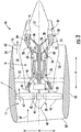
- FIG. 3 is a schematic cross-sectional view of a gas turbine engine in accordance with an exemplary embodiment of the present disclosure. More particularly, for the embodiment of FIG. 3 , the gas turbine engine is a high-bypass turbofan jet engine 10, referred to herein as "turbofan engine 10." As shown in FIG. 3 , the turbofan engine 10 defines an axial direction A (extending parallel to a longitudinal centerline 12 provided for reference) and a radial direction R. In general, the turbofan 10 includes a fan section 14 and a core turbine engine 16 disposed downstream from the fan section 14. Although described below with reference to a turbofan engine 10, the present disclosure is applicable to turbomachinery in general, including turbojet, turboprop and turboshaft gas turbine engines, including industrial and marine gas turbine engines and auxiliary power units.
- turbomachinery including turbojet, turboprop and turboshaft gas turbine engines, including industrial and marine gas turbine engines and auxiliary power units.
- the exemplary core turbine engine 16 depicted generally includes a substantially tubular outer casing 18 that defines an annular inlet 20.
- the outer casing 18 encases, in serial flow relationship, a compressor section including a booster or low pressure (LP) compressor 22 and a high pressure (HP) compressor 24; a combustion section 26; a turbine section including a high pressure (HP) turbine 28 and a low pressure (LP) turbine 30; and a jet exhaust nozzle section 32.
- a high pressure (HP) shaft or spool 34 drivingly connects the HP turbine 28 to the HP compressor 24.
- a low pressure (LP) shaft or spool 36 drivingly connects the LP turbine 30 to the LP compressor 22.
- the fan section 14 includes a variable pitch fan 38 having a plurality of fan blades 40 coupled to a disk 42 in a spaced apart manner.
- the fan blades 40 extend outwardly from disk 42 generally along the radial direction R.
- Each fan blade 40 is rotatable relative to the disk 42 about a pitch axis P by virtue of the fan blades 40 being operatively coupled to a suitable actuation member 44 configured to collectively vary the pitch of the fan blades 40 in unison.
- the fan blades 40, disk 42, and actuation member 44 are together rotatable about the longitudinal axis 12 by LP shaft 36 across an optional power gear box 46.
- the power gear box 46 includes a plurality of gears for stepping down the rotational speed of the LP shaft 36 to a more efficient rotational fan speed.
- the disk 42 is covered by rotatable front nacelle 48 aerodynamically contoured to promote an airflow through the plurality of fan blades 40.
- the exemplary fan section 14 includes an annular fan casing or outer nacelle 50 that circumferentially surrounds the fan 38 and/or at least a portion of the core turbine engine 16.
- the nacelle 50 may be configured to be supported relative to the core turbine engine 16 by a plurality of circumferentially-spaced outlet guide vanes 52.
- a downstream section 54 of the nacelle 50 may extend over an outer portion of the core turbine engine 16 so as to define a bypass airflow passage 56 therebetween.
- a volume of air 58 enters the turbofan 10 through an associated inlet 60 of the nacelle 50 and/or fan section 14.
- a first portion of the air 58 as indicated by arrows 62 is directed or routed into the bypass airflow passage 56 and a second portion of the air 58 as indicated by arrow 64 is directed or routed into the LP compressor 22.
- the ratio between the first portion of air 62 and the second portion of air 64 is commonly known as a bypass ratio.
- the pressure of the second portion of air 64 is then increased as it is routed through the high pressure (HP) compressor 24 and into the combustion section 26, where it is mixed with fuel and burned to provide combustion gases 66.
- HP high pressure
- the combustion gases 66 are routed through the HP turbine 28 where a portion of thermal and/or kinetic energy from the combustion gases 66 is extracted via sequential stages of HP turbine stator vanes 68 that are coupled to the outer casing 18 and HP turbine rotor blades 70 that are coupled to the HP shaft or spool 34, thus causing the HP shaft or spool 34 to rotate, thereby supporting operation of the HP compressor 24.
- the combustion gases 66 are then routed through the LP turbine 30 where a second portion of thermal and kinetic energy is extracted from the combustion gases 66 via sequential stages of LP turbine stator vanes 72 that are coupled to the outer casing 18 and LP turbine rotor blades 74 that are coupled to the LP shaft or spool 36, thus causing the LP shaft or spool 36 to rotate, thereby supporting operation of the LP compressor 22 and/or rotation of the fan 38.
- the combustion gases 66 are subsequently routed through the jet exhaust nozzle section 32 of the core turbine engine 16 to provide propulsive thrust. Simultaneously, the pressure of the first portion of air 62 is substantially increased as the first portion of air 62 is routed through the bypass airflow passage 56 before it is exhausted from a fan nozzle exhaust section 76 of the turbofan 10, also providing propulsive thrust.
- the HP turbine 28, the LP turbine 30, and the jet exhaust nozzle section 32 at least partially define a hot gas path 78 for routing the combustion gases 66 through the core turbine engine 16.
- FIG. 4 shows a diagram of an exemplary method 400 of forming a coating system on a surface of a substrate.
- a mullite/NOSC bondcoat is formed on the surface of the substrate to include a NOSC phase contained within a mullite phase, such as described above with respect to mullite/NOSC bondcoat 104.
- the mullite/NOSC bondcoat is formed by air plasma spray. In another embodiment, it is formed by suspension plasma spray where a liquid suspension of the desired chemistry is used for air plasma spray. In still another embodiment, the coating is formed by low pressure plasma spray. In yet another embodiment one or more of the coated layers may be formed by a slurry coating process followed by sintering of the layer. Different coating layers may be formed by one or more of these processes.
- an environmental barrier coating is formed on the mullite/ NOSC bondcoat. As described above, gaseous carbides are allowed to vent through the EBC.
- FIG. 5 shows an EBC 500 applied over a CMC substrate 502, where the EBC 500 included a bond coat 504 having a biphasic structure of mullite and silicon carbide, and a permeable outer layer 506.
- the bond coat 504 is applied directly on the CMC substrate 502.
- Silicon carbide in the bond coat 504 serves as the oxygen getter to prevent oxygen from attacking the substrate 502, upon oxidation, silicon carbide converts to silicon oxide (silica) and releases CO gas.
- Mullite serves as the matrix, and was selected based on its low oxygen permeability. In this configuration, the phase of silica oxidation product has certain degree of continuity so that by its recession and microcracking, CO has a pathway to get out of the bond coat.
- the outer layer 506 is designed to be permeable so that CO that is generated in the bond coat 504 can escape into the environment.
- the outer layer 506 can contain several sublayers of oxides, and gas permeability can be realized by a porous or columnar structure.
- the architecture schematically shown in FIG. 5 was formed using a slurry plasma spray, as shown in the examples in FIG. 6A and FIG. 6B .
- the upper layer was formed from a columnar alumina layer.
- the upper layer was formed from a combination of columnar alumina and YSZ (Yttria Stabilized Zirconia) sublayers. Both of these coatings were tested to evaluate several characteristics, including recession resistance under cyclic conditions, thermal shock resistance, and gas erosion resistance. These characteristics are evaluated by cyclic steam rig testing, JETs and HVOF testing, and interlaced testing combining these techniques.
- the coatings consistently demonstrated recession resistance of more than 500 hours in 2700 °F (about 1482 °C) cyclic steam test, the longest steam test went up to 1000 hours. Post-testing characterization of the cross-sections of the tested samples showed acceptable progression of degradation.
- the coating systems in Figures 6a and 6b are Mullite-SiC/Al 2 O 3 and Mullite-SiC/Al 2 O 3 /YSZ.
- Other examples of the coating architectures are Mullite-SiC/HfO 2 and Mullite-SiC/Al 2 O 3 /HfO 2 .
Landscapes
- Chemical & Material Sciences (AREA)
- Engineering & Computer Science (AREA)
- Ceramic Engineering (AREA)
- Materials Engineering (AREA)
- Structural Engineering (AREA)
- Organic Chemistry (AREA)
- Inorganic Chemistry (AREA)
- Mechanical Engineering (AREA)
- General Engineering & Computer Science (AREA)
- Turbine Rotor Nozzle Sealing (AREA)
- Compositions Of Oxide Ceramics (AREA)
Abstract
Description
- The present invention generally relates to bondcoats for use with environmental barrier coatings on ceramic components, particularly silicon-based ceramic matrix components, along with methods of their formation and use.
- Higher operating temperatures for gas turbine engines are continuously being sought in order to improve their efficiency. However, as operating temperatures increase, the high temperature durability of the components of the engine must correspondingly increase. Significant advances in high temperature capabilities have been achieved through the formulation of iron, nickel, and cobalt-based superalloys. Still, with many hot gas path components constructed from super alloys, thermal barrier coatings (TBCs) can be utilized to insulate the components and can sustain an appreciable temperature difference between the load-bearing alloys and the coating surface, thus limiting the thermal exposure of the structural component.
- While superalloys have found wide use for components used throughout gas turbine engines, and especially in the higher temperature sections, alternative lighter-weight substrate materials have been proposed, such as ceramic matrix composite (CMC) materials, in particular silicon carbide (SiC) fiber reinforced SiC and SiC/Si matrix composites, so called SiC/SiC composites.. CMC and monolithic ceramic components can be coated with environmental barrier coatings (EBCs) to protect them from the harsh environment of high temperature engine sections. EBCs can provide a dense, hermetic seal against the corrosive gases in the hot combustion environment.
- Silicon carbide and silicon nitride ceramics undergo oxidation in dry, high temperature environments. This oxidation produces a passive, silicon oxide scale on the surface of the material. In moist, high temperature environments containing water vapor, such as a turbine engine, both oxidation and recession occurs due to the formation of a passive silicon oxide scale and subsequent conversion of the silicon oxide to gaseous silicon hydroxide. To prevent recession in moist, high temperature environments, environmental barrier coatings (EBC's) are deposited onto silicon carbide and silicon nitride materials.
- Currently, EBC materials are made out of rare earth silicate compounds. These materials seal out water vapor, preventing it from reaching the silicon oxide scale on the silicon carbide or silicon nitride surface, thereby preventing recession. Such materials cannot prevent oxygen penetration, however, which results in oxidation of the underlying substrate. Oxidation of the substrate yields a passive silicon oxide scale, along with the release of carbonaceous or nitrous oxide gas. The carbonaceous (i.e., CO, CO2) or nitrous (i.e., NO, NO2, etc.) oxide gases cannot escape out through the dense EBC and thus, blisters form, which can cause spallation of the EBC. The use of a silicon bondcoat has been the solution to this blistering problem to date. The silicon bondcoat provides a layer that oxidizes (forming a passive silicon oxide layer beneath the EBC) without liberating a gaseous by-product.
- However, the presence of a silicon bondcoat limits the upper temperature of operation for the EBC because the melting point of silicon metal is relatively low. In use, the silicon bondcoat melts at coating temperatures of about 1414 °C, which is the melting point of silicon metal. Above these melting temperatures, the silicon bondcoat may delaminate from the underlying substrate, effectively removing the bondcoat and the EBC thereon. As such, it is desirable to have improved bondcoats in the EBC to achieve a higher operational temperature limit for the EBC.
- Aspects and advantages of the invention will be set forth in part in the following description, or may be obvious from the description, or may be learned through practice of the invention.
- A coated component is generally provided, along with methods of making and using the same. In one embodiment, the coated component includes a ceramic matrix composite (CMC) substrate comprising silicon carbide and having a surface; a mullite/NOSC bondcoat on the surface of the substrate; and an environmental barrier coating on the mullite/NOSC bondcoat. The mullite/NOSC bondcoat comprises a non-oxide silicon ceramic (NOSC) phase contained within a mullite phase, with the mullite/NOSC bondcoat comprising 60% to 95% by volume of the mullite phase, such as 65% to 93% by volume of the mullite phase (e.g., 75% to 90% by volume of the mullite phase).
- In certain embodiments, the mullite phase includes alumina and silica in a stoichiometric ratio within 10% of 3 to 2, such as about 3 to 2 up to about 3.5 to 2. In other embodiments, the mullite phase includes alumina and silica in a stoichiometric ratio within 10% of 2 to 1, such as about 2 to 1 up to about 2.25 to 1. In particular embodiments, the mullite phase may consists of alumina and silica.
- In certain embodiments, the NOSC phase may include silicon carbide, silicon nitride, silicon oxycarbide, silicon oxynitride, or a mixture thereof. For instance, the mullite/NOSC bondcoat may include 5% to 40% by volume NOSC, such as 7% to 35% by volume NOSC (e.g., 10% to 25% by volume NOSC).
- The environmental barrier coating may include a plurality of layers with at least one of the layers of the environmental barrier coating comprises a porous layer, such as a porous layer with interconnected porosity. In another embodiment, all of the layers may have interconnected porosity. In one particular embodiment, the porous layer may be adjacent to the mullite/NOSC bondcoat such that the porous layer defines the inner surface of the environmental barrier coating. For instance, the porous layer may include an aluminum oxide.
- The mullite/NOSC bondcoat may be configured to withstand exposure to operating temperatures of up to 1650 °C.
- In one embodiment, a method is provided for forming a coated component. For example, the method may include forming a mullite/NOSC bondcoat on a surface of a substrate and forming an environmental barrier coating on the mullite/NOSC bondcoat. The mullite/NOSC bondcoat includes a NOSC phase contained within a mullite phase, and the mullite/NOSC bondcoat comprises 60% to 95% by volume of the mullite phase.
- These and other features, aspects and advantages of the present invention will become better understood with reference to the following description and appended claims. The accompanying drawings, which are incorporated in and constitute a part of this specification, illustrate embodiments of the invention and, together with the description, serve to explain the principles of the invention.
- A full and enabling disclosure of the present invention, including the best mode thereof, directed to one of ordinary skill in the art, is set forth in the specification, which makes reference to the appended Figs., in which:
-
FIG. 1 is a cross-sectional side view of an exemplary coated component including a mullite bondcoat including a non-oxide silicon ceramic; -
FIG. 2 is a cross-sectional side view of an exemplary mullite bondcoat including a non-oxide silicon ceramic having with a continuous mullite phase with discrete non-oxide silicon ceramic -phases dispersed therein; -
FIG. 3 is a schematic cross-sectional view of an exemplary gas turbine engine according to various embodiments of the present subject matter; -
FIG. 4 is a diagram of an exemplary method of forming a mullite bondcoat including a non-oxide silicon ceramic; -
FIG. 5 shows a schematic diagram of an exemplary coated component formed according to the examples; -
FIG. 6A shows a cross section of an exemplary coated component made according to the Examples and having a bond coat of mullite and SiC with an upper layer formed from columnar alumina layer; and -
FIG. 6B shows a cross section of an exemplary coated component made according to the Examples and having a bond coat of mullite and SiC with an upper layer being a combination of columnar alumina and YSZ sublayers. - Repeat use of reference characters in the present specification and drawings is intended to represent the same or analogous features or elements of the present invention.
- Reference now will be made in detail to embodiments of the invention, one or more examples of which are illustrated in the drawings. Each example is provided by way of explanation of the invention, not limitation of the invention. In fact, it will be apparent to those skilled in the art that various modifications and variations can be made in the present invention without departing from the scope or spirit of the invention. For instance, features illustrated or described as part of one embodiment can be used with another embodiment to yield a still further embodiment. Thus, it is intended that the present invention covers such modifications and variations as come within the scope of the appended claims and their equivalents.
- As used herein, the terms "first", "second", and "third" may be used interchangeably to distinguish one component from another and are not intended to signify location or importance of the individual components.
- Chemical elements are discussed in the present disclosure using their common chemical abbreviation, such as commonly found on a periodic table of elements. For example, hydrogen is represented by its common chemical abbreviation H; helium is represented by its common chemical abbreviation He; and so forth. As used herein, "RE" refers to a rare earth element or a mixture of rare earth elements. More specifically, the " RE" refers to the rare earth elements of scandium (Sc), yttrium (Y), lanthanum (La), cerium (Ce), praseodymium (Pr), neodymium (Nd), promethium (Pm), samarium (Sm), europium (Eu), gadolinium (Gd), terbium (Tb), dysprosium (Dy), holmium (Ho), erbium (Er), thulium (Tm), ytterbium (Yb), lutetium (Lu), or mixtures thereof.
- As used herein, the term "substantially free" means no more than an insignificant trace amount present and encompasses completely free (e.g., 0 molar % up to 0.01 molar %).
- In the present disclosure, when a layer is being described as "on" or "over" another layer or substrate, it is to be understood that the layers can either be directly contacting each other or have another layer or feature between the layers, unless expressly stated to the contrary. Thus, these terms are simply describing the relative position of the layers to each other and do not necessarily mean "on top of' since the relative position above or below depends upon the orientation of the device to the viewer.
- A coated component is generally provided that includes a mullite bondcoat having a non-oxide silicon ceramic ("NOSC") contained therein. The mullite bondcoat including a non-oxide silicon ceramic (referred to herein as a "mullite/NOSC bondcoat") is generally positioned between the surface of the substrate and an environmental barrier coating (EBC) thereon. Generally, the mullite/NOSC bondcoat is formed from a non-oxide, silicon ceramic (e.g., silicon carbide, silicon nitride, silicon carbonitride, silicon oxycarbide, silicon oxynitride, and/or mixtures thereof) that serves as a sacrificial material to react with oxygen in service to form a gaseous oxide (e.g., carbon oxides and/or nitrous oxides) that can escape through the overlying EBC layers. Thus, oxidation of the underlying substrate may be prevented.
- Referring to
FIG. 1 , an exemplarycoated component 100 is shown formed from asubstrate 102 having asurface 103 with acoating system 106 thereon. Thesubstrate 102 is formed from a ceramic matrix composite ("CMC") material, such as a silicon based, non-oxide ceramic matrix composite. As used herein, "CMC" refers to a silicon-containing, or oxide-oxide, matrix and reinforcing material. As used herein, "monolithic ceramics" refers to materials without fiber reinforcement (e.g., having the matrix material only). Herein, CMCs and monolithic ceramics are collectively referred to as "ceramics." In particular embodiments, theCMC substrate 102 includes silicon carbide (SiC) within its ceramic matrix and fibers (when present). - Generally, the
coating system 106 includes a mullite/NOSC bondcoat 104 on thesurface 103 of the substrate, and anEBC 108 on the mullite/NOSC bondcoat 104. In the embodiment shown, the mullite/NOSC bondcoat 104 is directly on thesurface 103 without any layer therebetween. - In the exemplary embodiment of
FIG. 2 , the mullite/NOSC bondcoat 104 has acontinuous mullite phase 112 with discrete NOSC-phases 110 dispersed therein. Although shown as discrete NOSC-phases 110, some continuity of the NOSC-phase is acceptable, particularly at NOSC concentration above about 10% by volume or above about 15% by volume. For example, the NOSC material may form particles that touch each other within the mullite phase, becoming continuous in nature. In other embodiments, the mullite/NOSC bondcoat 104 has acontinuous mullite phase 112, while theNOSC phase 110 is also interconnected and continuous therein. - Mullite generally has a relatively slow diffusion rate for oxygen at all temperatures of interest, even up to about 1650 °C (e.g., about 1200 °C to about 1650 °C). At temperatures over about 1200 °C, it is believed that the only other crystalline oxide that has lower oxygen diffusion rate than mullite is alumina, which has a very high expansion coefficient compared to the substrate and cannot be deposited as dense coatings without spallation. Although mullite has a coefficient of thermal expansion ("CTE") that is similar to that of
SiC CMC substrates 102, the CTE of mullite is not an exact match to SiC. The slight mismatch of CTE of mullite and SiC could lead to problems related to thermal expansion, such as cracking and/or delamination, if the mullite/NOSC bondcoat 104 is too thick. For example, it is believed that a mullite/NOSC bondcoat 104 having a thickness of 20 mils (i.e., 508 µm) would lead to problems related to the CTE mismatch after repeated exposure to the operating temperatures. On the other hand, it is believed that a mullite/NOSC bondcoat 104 having a maximum thickness of 10 mils or less, such as 1 mil to 10 mils (i.e., 254 µm or less, such as 25.4 µm to 254 µm), would survive such operating temperatures without significant problems from the CTE mismatch. In one particular embodiment, the mullite/NOSC bondcoat 104 has a maximum thickness of 5 mils, such as 3 mils to 5 mils (i.e., 127 µm, such as 76.2 µm to 127 µm). - The
mullite phase 112 is included in the mullite/NOSC bondcoat 104 in an amount to provide structural integrity to the mullite/NOSC bondcoat 104 while theNOSC phase 110 is sacrificed over multiple exposures to oxygen at operating temperatures. As such, at least 60% of the mullite/NOSC bondcoat 104 may be mullite. In particular embodiments, the mullite/NOSC bondcoat 104 may include 60% to 95% by volume mullite, such as 65% to 93% by volume mullite (e.g., 75% to 90% by volume mullite). - Conversely, the
NOSC phase 110 is included in the mullite/NOSC bondcoat 104 in an amount sufficient to serve as a sacrificial oxygen getter. In one particular embodiment, theNOSC phase 110 may be formed from silicon carbide (i.e., SiC), silicon nitride (i.e., Si3N5), or a mixture thereof. Both SiC and SiN have melting temperatures that are sufficient to prevent melting at the operating temperatures, and both will react to oxygen to form gaseous oxides (e.g., carbon oxides and nitrous oxides, respectively) that can be vented from the porous EBC. As such, theNOSC phase 110 prevents oxygen from reaching to theunderlying substrate 102. - For example, the mullite/NOSC bondcoat 104 may, in certain embodiments, include 5% to 40% by volume of the
NOSC phase 110, such as 7% to 35% by volume of the NOSC phase 110 (e.g., 10% to 25% by volume of the NOSC phase 110). In particular embodiments, for example, theNOSC phase 110 may include 5% to 40% by volume of SiC, such as about 7% to 35% by weight of SiC (e.g., 10% to 25% by volume of SiC). - In particular embodiments, the
mullite phase 112 is formed from crystallized mullite having a melting temperature that is about 1825 °C to 1860 °C (e.g., about 1840 °C), and is generally unreactive with the NOSC phase 110 (e.g., SiC). - Mullite is a chemical compound of alumina and silica with an alumina (Al2O3) and Silica (SiO2) ratio of about 3 to 2 (e.g., within 10 mole % of 3 to 2 of alumina to silica). A ratio of about 2 to 1 has also been reported (e.g., within 10 mole % of 2 to 1 of alumina to silica). In one embodiment, the mullite layer may contain excess of alumina, up to about 10 mole % of excess alumina. For example, the mullite phase may include alumina and silica in a stoichiometric ratio of about 3 to 2 up to about 3.5 to 2 or in a stoichiometric ratio of about 2 to 1 up to about 2.25 to 1. In another embodiment, the mullite layer may contain excess of silica. If there is excess silica, it should preferably be not continuous. As used here, "alumina" refers to aluminum oxide in the form of Al2O3. As used here, "silica" refers to silicon oxide in the form of SiO2.
- In one embodiment, a thermally grown oxide ("TGO") layer may form directly on the outer surface of the
NOSC phase 110, such as a layer of silicon oxide (sometimes referred to as "silicon oxide scale" or "silica scale"), during exposure to oxygen (e.g., during manufacturing and/or use) of thecomponent 100. - As stated above, the
substrate 102 may be formed from a CMC material, such as a silicon based, non-oxide ceramic matrix composite. Some examples of CMCs acceptable for use herein can include, but are not limited to, materials having a matrix comprising non-oxide silicon-based materials such as silicon carbide, silicon nitride, silicon oxycarbides, silicon oxynitrides, and mixtures thereof. Some examples of CMCs acceptable for use herein can include, but are not limited to, materials having reinforcing fibers comprising carbon fibers and/or non-oxide silicon-based materials such as silicon carbide, silicon nitride, silicon oxycarbides, silicon oxynitrides, and mixtures thereof. Examples include, but are not limited to, CMCs with silicon carbide matrix and silicon carbide fiber; Si-SiC matrix and silicon carbide fiber; silicon carbide matrix and carbon fiber; silicon nitride matrix and silicon carbide fiber; and silicon carbide/silicon nitride matrix mixture and silicon carbide fiber. In one particular embodiment, the matrix material of thesubstrate 102 may be substantially identical in composition to the NOSC material within theNOSC phase 110. For example, both the matrix material of thesubstrate 102 and the NOSC material within theNOSC phase 110 may be SiC. - As stated above, the mullite/NOSC bondcoat 104 may be used in conjunction with an
EBC 108 to form acoated component 100 with an increased operating temperature compared to that using a silicon bondcoat. TheEBC 108 may include any combination of one or more layers formed from materials selected from typical EBC or thermal barrier coating ("TBC") layer chemistries, including but not limited to rare earth silicates (e.g., mono-silicates and di-silicates), aluminosilicates (e.g., mullite, barium strontium aluminosilicate (BSAS), rare earth aluminosilicates, etc.), hafnia, zirconia, stabilized hafnia, stabilized zirconia, rare earth hafnates, rare earth zirconates, rare earth gallium oxide, etc. - The microstructure requirements of the outer coating may depend upon the amount of NOSC in mullite/
NOSC bondcoat 104. For example, when the NOSC includes SiC, the microstructure requirements of the outer coating may depend upon the amount of SiC in the mullite/NOSC bondcoat 104 (i.e., in the mullite/SiC bondcoat of this embodiment). For small amounts of SiC, the amount of CO gas formation may be small enough that it would cause localized blistering only, rather than spallation of the outer layers, if the outer layers are fully dense and do not allow the CO gas to escape. Therefore, in one embodiment, the outer EBC layers contain at least one dense, hermetic layer. On the other hand, if the concentration of SiC is fairly high (for example, over about 20 mole percent, or over about 30 mole %), the amount of CO gas formation may be significant enough to cause the spallation of the outer layers. Therefore, in such embodiments, the outer EBC layers may contain enough porosity to provide a continuous path for CO to escape. The amount of total porosity should preferably be as low as possible but high enough to form a continuous path for CO to escape, which may happen at porosity levels of over about 10 volume percent. - The
EBC 108 may be formed from a plurality ofindividual layers 114. In the embodiments shown,EBC 108 includes a porous layer 116 with interconnected porosity positioned in directly on the mullite/NOSC bondcoat 104. The porous layer 116 allows for gaseous oxides to escape theEBC 108 upon their formation in the mullite/NOSC bondcoat 104. In one embodiment, each of thelayers 114 of theEBC 108 are porous layers 116. - The
coated component 100 is particularly suitable for use as a component found in high temperature environments, such as those present in gas turbine engines, for example, combustor components, turbine blades, shrouds, nozzles, heat shields, and vanes. In particular, the turbine component can be aCMC component 100 positioned within a hot gas flow path of the gas turbine such that thecoating system 106 forms an environmental barrier for theunderlying substrate 102 to protect thecomponent 100 within the gas turbine when exposed to the hot gas flow path. In certain embodiments, the mullite/NOSC bondcoat 104 is configured such that thecoated component 100 is exposed to operating temperatures of about 1475 °C to about 1650°C. -
FIG. 3 is a schematic cross-sectional view of a gas turbine engine in accordance with an exemplary embodiment of the present disclosure. More particularly, for the embodiment ofFIG. 3 , the gas turbine engine is a high-bypassturbofan jet engine 10, referred to herein as "turbofan engine 10." As shown inFIG. 3 , theturbofan engine 10 defines an axial direction A (extending parallel to alongitudinal centerline 12 provided for reference) and a radial direction R. In general, theturbofan 10 includes afan section 14 and acore turbine engine 16 disposed downstream from thefan section 14. Although described below with reference to aturbofan engine 10, the present disclosure is applicable to turbomachinery in general, including turbojet, turboprop and turboshaft gas turbine engines, including industrial and marine gas turbine engines and auxiliary power units. - The exemplary
core turbine engine 16 depicted generally includes a substantially tubularouter casing 18 that defines anannular inlet 20. Theouter casing 18 encases, in serial flow relationship, a compressor section including a booster or low pressure (LP)compressor 22 and a high pressure (HP)compressor 24; acombustion section 26; a turbine section including a high pressure (HP)turbine 28 and a low pressure (LP)turbine 30; and a jetexhaust nozzle section 32. A high pressure (HP) shaft orspool 34 drivingly connects theHP turbine 28 to theHP compressor 24. A low pressure (LP) shaft orspool 36 drivingly connects theLP turbine 30 to theLP compressor 22. - For the embodiment depicted, the
fan section 14 includes avariable pitch fan 38 having a plurality offan blades 40 coupled to adisk 42 in a spaced apart manner. As depicted, thefan blades 40 extend outwardly fromdisk 42 generally along the radial direction R. Eachfan blade 40 is rotatable relative to thedisk 42 about a pitch axis P by virtue of thefan blades 40 being operatively coupled to asuitable actuation member 44 configured to collectively vary the pitch of thefan blades 40 in unison. Thefan blades 40,disk 42, andactuation member 44 are together rotatable about thelongitudinal axis 12 byLP shaft 36 across an optionalpower gear box 46. Thepower gear box 46 includes a plurality of gears for stepping down the rotational speed of theLP shaft 36 to a more efficient rotational fan speed. - Referring still to the exemplary embodiment of
FIG. 3 , thedisk 42 is covered byrotatable front nacelle 48 aerodynamically contoured to promote an airflow through the plurality offan blades 40. Additionally, theexemplary fan section 14 includes an annular fan casing orouter nacelle 50 that circumferentially surrounds thefan 38 and/or at least a portion of thecore turbine engine 16. It should be appreciated that thenacelle 50 may be configured to be supported relative to thecore turbine engine 16 by a plurality of circumferentially-spaced outlet guide vanes 52. Moreover, adownstream section 54 of thenacelle 50 may extend over an outer portion of thecore turbine engine 16 so as to define abypass airflow passage 56 therebetween. - During operation of the
turbofan engine 10, a volume ofair 58 enters theturbofan 10 through an associatedinlet 60 of thenacelle 50 and/orfan section 14. As the volume ofair 58 passes across thefan blades 40, a first portion of theair 58 as indicated byarrows 62 is directed or routed into thebypass airflow passage 56 and a second portion of theair 58 as indicated byarrow 64 is directed or routed into theLP compressor 22. The ratio between the first portion ofair 62 and the second portion ofair 64 is commonly known as a bypass ratio. The pressure of the second portion ofair 64 is then increased as it is routed through the high pressure (HP)compressor 24 and into thecombustion section 26, where it is mixed with fuel and burned to providecombustion gases 66. - The
combustion gases 66 are routed through theHP turbine 28 where a portion of thermal and/or kinetic energy from thecombustion gases 66 is extracted via sequential stages of HP turbine stator vanes 68 that are coupled to theouter casing 18 and HPturbine rotor blades 70 that are coupled to the HP shaft orspool 34, thus causing the HP shaft orspool 34 to rotate, thereby supporting operation of theHP compressor 24. Thecombustion gases 66 are then routed through theLP turbine 30 where a second portion of thermal and kinetic energy is extracted from thecombustion gases 66 via sequential stages of LPturbine stator vanes 72 that are coupled to theouter casing 18 and LPturbine rotor blades 74 that are coupled to the LP shaft orspool 36, thus causing the LP shaft orspool 36 to rotate, thereby supporting operation of theLP compressor 22 and/or rotation of thefan 38. - The
combustion gases 66 are subsequently routed through the jetexhaust nozzle section 32 of thecore turbine engine 16 to provide propulsive thrust. Simultaneously, the pressure of the first portion ofair 62 is substantially increased as the first portion ofair 62 is routed through thebypass airflow passage 56 before it is exhausted from a fannozzle exhaust section 76 of theturbofan 10, also providing propulsive thrust. TheHP turbine 28, theLP turbine 30, and the jetexhaust nozzle section 32 at least partially define ahot gas path 78 for routing thecombustion gases 66 through thecore turbine engine 16. - Methods are also generally provided for coating a ceramic component. For example,
FIG. 4 shows a diagram of anexemplary method 400 of forming a coating system on a surface of a substrate. At 402, a mullite/NOSC bondcoat is formed on the surface of the substrate to include a NOSC phase contained within a mullite phase, such as described above with respect to mullite/NOSC bondcoat 104. - In one embodiment, the mullite/NOSC bondcoat is formed by air plasma spray. In another embodiment, it is formed by suspension plasma spray where a liquid suspension of the desired chemistry is used for air plasma spray. In still another embodiment, the coating is formed by low pressure plasma spray. In yet another embodiment one or more of the coated layers may be formed by a slurry coating process followed by sintering of the layer. Different coating layers may be formed by one or more of these processes.
- At 404, an environmental barrier coating (EBC) is formed on the mullite/ NOSC bondcoat. As described above, gaseous carbides are allowed to vent through the EBC.
-
FIG. 5 shows anEBC 500 applied over aCMC substrate 502, where theEBC 500 included abond coat 504 having a biphasic structure of mullite and silicon carbide, and a permeableouter layer 506. Thebond coat 504 is applied directly on theCMC substrate 502. Silicon carbide in thebond coat 504 serves as the oxygen getter to prevent oxygen from attacking thesubstrate 502, upon oxidation, silicon carbide converts to silicon oxide (silica) and releases CO gas. Mullite serves as the matrix, and was selected based on its low oxygen permeability. In this configuration, the phase of silica oxidation product has certain degree of continuity so that by its recession and microcracking, CO has a pathway to get out of the bond coat. Theouter layer 506 is designed to be permeable so that CO that is generated in thebond coat 504 can escape into the environment. Theouter layer 506 can contain several sublayers of oxides, and gas permeability can be realized by a porous or columnar structure. - The architecture schematically shown in
FIG. 5 was formed using a slurry plasma spray, as shown in the examples inFIG. 6A and FIG. 6B . In the embodiment ofFIG. 6A , the upper layer was formed from a columnar alumina layer. In the embodiment ofFIG. 6B , the upper layer was formed from a combination of columnar alumina and YSZ (Yttria Stabilized Zirconia) sublayers. Both of these coatings were tested to evaluate several characteristics, including recession resistance under cyclic conditions, thermal shock resistance, and gas erosion resistance. These characteristics are evaluated by cyclic steam rig testing, JETs and HVOF testing, and interlaced testing combining these techniques. The coatings consistently demonstrated recession resistance of more than 500 hours in 2700 °F (about 1482 °C) cyclic steam test, the longest steam test went up to 1000 hours. Post-testing characterization of the cross-sections of the tested samples showed acceptable progression of degradation. - The coating systems in
Figures 6a and 6b are Mullite-SiC/Al2O3 and Mullite-SiC/Al2O3/YSZ. Other examples of the coating architectures are Mullite-SiC/HfO2 and Mullite-SiC/Al2O3/HfO2. - This written description uses examples to disclose the invention, including the best mode, and also to enable any person skilled in the art to practice the invention, including making and using any devices or systems and performing any incorporated methods. The patentable scope of the invention is defined by the claims, and may include other examples that occur to those skilled in the art. Such other examples are intended to be within the scope of the claims if they include structural elements that do not differ from the literal language of the claims, or if they include equivalent structural elements with insubstantial differences from the literal languages of the claims.
- Further aspects of the invention are provided by the subject matter of the following clauses:
- 1. A coated component comprising:
- a ceramic matrix composite (CMC) substrate comprising silicon carbide and having a surface;
- a mullite/NOSC bondcoat on the surface of the substrate, wherein the mullite/NOSC bondcoat comprises a non-oxide silicon ceramic (NOSC) phase contained within a mullite phase, and wherein the mullite/NOSC bondcoat comprises 60% to 95% by volume of the mullite phase; and
- an environmental barrier coating on the mullite/NOSC bondcoat.
- 2. The coated component of any preceding clause, wherein the mullite/NOSC bondcoat comprises 65% to 93% by volume of the mullite phase.
- 3. The coated component of any preceding clause, wherein the mullite/NOSC bondcoat comprises 75% to 90% by volume of the mullite phase.
- 4. The coated component of any preceding clause, wherein the mullite phase comprises alumina and silica in a stoichiometric ratio within 10% of 3 to 2.
- 5. The coated component of any preceding clause, wherein the mullite phase comprises alumina and silica in a stoichiometric ratio within 10% of 2 to 1.
- 6. The coated component of any preceding clause, wherein the mullite phase consists of alumina and silica.
- 7. The coated component of any preceding clause, wherein the mullite phase comprises alumina and silica in a stoichiometric ratio of about 3 to 2 up to about 3.5 to 2.
- 8. The coated component of any preceding clause, wherein the mullite phase comprises alumina and silica in a stoichiometric ratio of about 2 to 1 up to about 2.25 to 1.
- 9. The coated component of any preceding clause, wherein the NOSC phase comprises silicon carbide, silicon nitride, silicon oxycarbide, silicon oxynitride, or a mixture thereof.
- 10. The coated component of any preceding clause, wherein the NOSC phase consists of silicon carbide.
- 11. The coated component of any preceding clause, wherein the mullite/NOSC bondcoat comprises 5% to 40% by volume NOSC.
- 12. The coated component of any preceding clause, wherein the mullite/NOSC bondcoat comprises 7% to 35% by volume NOSC.
- 13. The coated component of any preceding clause, wherein the mullite/NOSC bondcoat comprises 10% to 25% by volume NOSC.
- 14. The coated component of any preceding clause, wherein the mullite phase is a continuous phase, and wherein the NOSC forms a plurality of discrete particulate phases within the mullite phase.
- 15. The coated component of any preceding clause, wherein the mullite phase is a continuous phase, and wherein the NOSC particulate phase is also interconnected and continuous.
- 16. The coated component of any preceding clause, wherein the environmental barrier coating comprises a plurality of layers with at least one of the layers of the environmental barrier coating comprises a porous layer with interconnected porosity.
- 17. The coated component of any preceding clause, wherein all of the layers have interconnected porosity.
- 18. The coated component of any preceding clause, wherein the porous layer is adjacent to the mullite/NOSC bondcoat such that the porous layer defines the inner surface of the environmental barrier coating, and wherein the porous layer comprises an aluminum oxide.
- 19. The coated component of any preceding clause, wherein the mullite/NOSC bondcoat is configured to withstand exposure to operating temperatures of up to 1650 °C.
- 20. A method of forming a coated component, the method comprising:
- forming a mullite/NOSC bondcoat on a surface of a substrate, wherein the mullite/NOSC bondcoat comprises a NOSC phase contained within a mullite phase, and wherein the mullite/NOSC bondcoat comprises 60% to 95% by volume of the mullite phase; and
- forming an environmental barrier coating on the mullite/NOSC bondcoat such that the NOSC phase is contained within mullite phase between the surface of the substrate and an inner surface of the environmental barrier coating.
Claims (15)
- A coated component (100) comprising:a ceramic matrix composite (CMC) substrate (102) comprising silicon carbide and having a surface (103);a mullite/nosc bondcoat (104) on the surface (103) of the substrate (102), wherein the mullite/nosc bondcoat (104) comprises a non-oxide silicon ceramic (NOSC) phase contained within a mullite phase (112), and wherein the mullite/nosc bondcoat (104) comprises 60% to 95% by volume of the mullite phase (112); andan environmental barrier coating on the mullite/nosc bondcoat (104).
- The coated component (100) as in claim 1, wherein the mullite/nosc bondcoat (104) comprises 75% to 90% by volume of the mullite phase (112).
- The coated component (100) as in claim 1 or 2, wherein the mullite phase (112) comprises alumina and silica in a stoichiometric ratio within 10% of 3 to 2.
- The coated component (100) as any of claims 1 to 3, wherein the mullite phase (112) comprises alumina and silica in a stoichiometric ratio within 10% of 2 to 1.
- The coated component (100) as any of claims 1 to 4, wherein the mullite phase (112) consists of alumina and silica.
- The coated component (100) as in any of claims 1 to 5, wherein the nose phase (110) comprises silicon carbide, silicon nitride, silicon oxycarbide, silicon oxynitride, or a mixture thereof.
- The coated component (100) as in any of claims 1 to 6, wherein the nosc phase (110) consists of silicon carbide.
- The coated component (100) as in any of claims 1 to 7, wherein the mullite/nosc bondcoat (104) comprises 5% to 40% by volume NOSC.
- The coated component (100) as in any of claims 1 to 8, wherein the mullite/nosc bondcoat (104) comprises 10% to 25% by volume NOSC.
- The coated component (100) as in any of claims 1 to 9, wherein the mullite phase (112) is a continuous phase, and wherein the NOSC forms a plurality of discrete particulate phases within the mullite phase (112).
- The coated component (100) as in any of claims 1 to 10, wherein the mullite phase (112) is a continuous phase, and wherein the NOSC particulate phase is also interconnected and continuous.
- The coated component (100) as in any of claims 1 to 11, wherein the environmental barrier coating comprises a plurality of layers (114) with at least one of the layers (114) of the environmental barrier coating comprises a porous layer (116) with interconnected porosity.
- The coated component (100) as in claim 12, wherein all of the layers (114) have interconnected porosity.
- The coated component (100) as in claim 12 or 13, wherein the porous layer (116) is adjacent to the mullite/nosc bondcoat (104) such that the porous layer (116) defines the inner surface (103) of the environmental barrier coating, and wherein the porous layer (116) comprises an aluminum oxide.
- A method of forming a coated component (100), the method comprising:forming a mullite/nosc bondcoat (104) on a surface (103) of a substrate (102), wherein the mullite/nosc bondcoat (104) comprises a nosc phase (110) contained within a mullite phase (112), and wherein the mullite/nosc bondcoat (104) comprises 60% to 95% by volume of the mullite phase (112); andforming an environmental barrier coating on the mullite/nosc bondcoat (104) such that the nosc phase (110) is contained within mullite phase (112) between the surface (103) of the substrate (102) and an inner surface (103) of the environmental barrier coating.
Applications Claiming Priority (1)
| Application Number | Priority Date | Filing Date | Title |
|---|---|---|---|
| US16/229,468 US10927046B2 (en) | 2018-12-21 | 2018-12-21 | EBC with mullite bondcoat having a non-oxide silicon ceramic |
Publications (2)
| Publication Number | Publication Date |
|---|---|
| EP3670479A1 true EP3670479A1 (en) | 2020-06-24 |
| EP3670479B1 EP3670479B1 (en) | 2021-05-26 |
Family
ID=68886954
Family Applications (1)
| Application Number | Title | Priority Date | Filing Date |
|---|---|---|---|
| EP19215421.9A Active EP3670479B1 (en) | 2018-12-21 | 2019-12-11 | Environmental barrier coating with mullite bondcoat comprising a non-oxide silicon ceramic |
Country Status (5)
| Country | Link |
|---|---|
| US (1) | US10927046B2 (en) |
| EP (1) | EP3670479B1 (en) |
| JP (1) | JP7106511B2 (en) |
| CN (1) | CN111348939B (en) |
| CA (1) | CA3064882C (en) |
Cited By (1)
| Publication number | Priority date | Publication date | Assignee | Title |
|---|---|---|---|---|
| FR3128709A1 (en) * | 2021-11-04 | 2023-05-05 | Safran Ceramics | METHOD FOR DEPOSITING AN ENVIRONMENTAL BARRIER ON A COMPOSITE MATERIAL PART WITH A CERAMIC MATRIX |
Families Citing this family (2)
| Publication number | Priority date | Publication date | Assignee | Title |
|---|---|---|---|---|
| US11479515B2 (en) * | 2018-12-21 | 2022-10-25 | General Electric Company | EBC with mullite bondcoat that includes an oxygen getter phase |
| CN115196951B (en) * | 2022-07-19 | 2023-02-24 | 湖南工业大学 | Modified carbon fiber-mullite ceramic wave-absorbing material with multilayer structure and preparation method thereof |
Citations (2)
| Publication number | Priority date | Publication date | Assignee | Title |
|---|---|---|---|---|
| US20020025454A1 (en) * | 1998-04-27 | 2002-02-28 | Hongyu Wang | Ceramic with preferential oxygen reactive layer |
| US20140272168A1 (en) * | 2013-03-12 | 2014-09-18 | Rolls-Royce Corporation | Method for fabricating multilayer environmental barrier coatings |
Family Cites Families (21)
| Publication number | Priority date | Publication date | Assignee | Title |
|---|---|---|---|---|
| US6607852B2 (en) | 2001-06-27 | 2003-08-19 | General Electric Company | Environmental/thermal barrier coating system with silica diffusion barrier layer |
| US6929852B2 (en) | 2002-08-08 | 2005-08-16 | Siemens Westinghouse Power Corporation | Protective overlayer for ceramics |
| DE10250037B3 (en) * | 2002-10-25 | 2004-05-13 | Forschungszentrum Jülich GmbH | Protective layer system for non-oxide, Si-containing substrates and its use |
| US7063894B2 (en) * | 2003-05-22 | 2006-06-20 | United Technologies Corporation | Environmental barrier coating for silicon based substrates |
| US7300702B2 (en) | 2003-08-18 | 2007-11-27 | Honeywell International, Inc. | Diffusion barrier coating for Si-based components |
| US7108925B2 (en) * | 2003-09-22 | 2006-09-19 | Siemens Power Generation, Inc. | High temperature insulation utilizing zirconia-hafnia |
| FR2899226B1 (en) | 2006-04-04 | 2008-07-04 | Snecma Propulsion Solide Sa | PIECE OF COMPOSITE MATERIAL WITH CERAMIC MATRIX CONTAINING SILICON, PROTECTED AGAINST CORROSION. |
| US8658255B2 (en) | 2008-12-19 | 2014-02-25 | General Electric Company | Methods for making environmental barrier coatings and ceramic components having CMAS mitigation capability |
| US20110027557A1 (en) * | 2009-07-31 | 2011-02-03 | Glen Harold Kirby | Solvent based environmental barrier coatings for high temperature ceramic components |
| EP2524069B1 (en) | 2010-01-11 | 2018-03-07 | Rolls-Royce Corporation | Features for mitigating thermal or mechanical stress on an environmental barrier coating |
| US20130260130A1 (en) | 2012-03-30 | 2013-10-03 | General Electric Company | Fiber-reinforced barrier coating, method of applying barrier coating to component and turbomachinery component |
| CN104446670B (en) * | 2014-11-28 | 2016-10-05 | 中国人民解放军国防科学技术大学 | C/SiC composite material surface coating system and preparation method thereof |
| US20160376691A1 (en) | 2015-05-27 | 2016-12-29 | University Of Virginia Patent Foundation | Multilayered thermal and environmental barrier coating (ebc) for high temperature applications and method thereof |
| CN105000917B (en) * | 2015-08-14 | 2017-04-12 | 中南大学 | Preparation method of mullite oxidation resistant coating |
| EP3337773B1 (en) | 2015-08-18 | 2024-09-25 | General Electric Company | Dense environmental barrier coating compositions |
| CN105110817B (en) * | 2015-08-19 | 2017-12-15 | 中国人民解放军国防科学技术大学 | Lacquer systems of FRCMC and preparation method thereof |
| CN105384467B (en) * | 2015-12-14 | 2017-08-25 | 中国航空工业集团公司北京航空制造工程研究所 | A kind of environment barrier coating and preparation method for ceramic matric composite matrix |
| CN105503272B (en) | 2015-12-22 | 2018-06-29 | 中南大学 | A kind of preparation method of the composite material of baric strontium aluminosilicate/mullite/SiC three-layer composite structure coatings |
| JP6696802B2 (en) | 2016-03-11 | 2020-05-20 | 一般財団法人ファインセラミックスセンター | Environment-resistant coating material |
| CN106747670A (en) * | 2016-05-30 | 2017-05-31 | 北京航空航天大学 | A kind of Environmental Barrier Coatings on Si-based Ceramics for polynary carbon and ceramic matric composite and preparation method thereof |
| US11479515B2 (en) * | 2018-12-21 | 2022-10-25 | General Electric Company | EBC with mullite bondcoat that includes an oxygen getter phase |
-
2018
- 2018-12-21 US US16/229,468 patent/US10927046B2/en active Active
-
2019
- 2019-12-05 JP JP2019220402A patent/JP7106511B2/en active Active
- 2019-12-11 EP EP19215421.9A patent/EP3670479B1/en active Active
- 2019-12-12 CA CA3064882A patent/CA3064882C/en active Active
- 2019-12-19 CN CN201911319261.9A patent/CN111348939B/en active Active
Patent Citations (2)
| Publication number | Priority date | Publication date | Assignee | Title |
|---|---|---|---|---|
| US20020025454A1 (en) * | 1998-04-27 | 2002-02-28 | Hongyu Wang | Ceramic with preferential oxygen reactive layer |
| US20140272168A1 (en) * | 2013-03-12 | 2014-09-18 | Rolls-Royce Corporation | Method for fabricating multilayer environmental barrier coatings |
Cited By (2)
| Publication number | Priority date | Publication date | Assignee | Title |
|---|---|---|---|---|
| FR3128709A1 (en) * | 2021-11-04 | 2023-05-05 | Safran Ceramics | METHOD FOR DEPOSITING AN ENVIRONMENTAL BARRIER ON A COMPOSITE MATERIAL PART WITH A CERAMIC MATRIX |
| WO2023079230A1 (en) * | 2021-11-04 | 2023-05-11 | Safran Ceramics | Method for depositing an environmental barrier on a part made of composite material having a ceramic matrix |
Also Published As
| Publication number | Publication date |
|---|---|
| US10927046B2 (en) | 2021-02-23 |
| JP2020100544A (en) | 2020-07-02 |
| CN111348939B (en) | 2022-07-15 |
| JP7106511B2 (en) | 2022-07-26 |
| CN111348939A (en) | 2020-06-30 |
| CA3064882A1 (en) | 2020-06-21 |
| EP3670479B1 (en) | 2021-05-26 |
| CA3064882C (en) | 2022-04-12 |
| US20200199032A1 (en) | 2020-06-25 |
Similar Documents
| Publication | Publication Date | Title |
|---|---|---|
| CA3064602C (en) | Ebc with mullite bondcoat that includes an oxygen getter phase | |
| US11492298B2 (en) | Silicon bond coat with columnar grains and methods of its formation | |
| US11578008B2 (en) | Silicon compositions containing boron and methods of forming the same | |
| EP3670479B1 (en) | Environmental barrier coating with mullite bondcoat comprising a non-oxide silicon ceramic | |
| WO2018050084A1 (en) | Silicon-based materials containing boron | |
| US20190233344A1 (en) | Silicon-Based Materials Containing Indium and Methods of Forming the Same | |
| CA3130995C (en) | Compositions containing gallium and/or indium and methods of forming the same | |
| US11401217B2 (en) | Bond coatings having a silicon-phase contained within a refractory phase | |
| US20200039886A1 (en) | Silicon Bond Coat with Amorphous Structure and Methods of Its Formation | |
| US10138740B2 (en) | Silicon-based materials containing gallium and methods of forming the same | |
| US10294112B2 (en) | Silicon compositions containing boron and methods of forming the same | |
| US10259716B2 (en) | Boron doped rare earth metal oxide compound | |
| WO2018052741A1 (en) | Silicon compositions containing boron and methods of forming the same | |
| US11746066B2 (en) | Compositions containing gallium and/or indium and methods of forming the same |
Legal Events
| Date | Code | Title | Description |
|---|---|---|---|
| PUAI | Public reference made under article 153(3) epc to a published international application that has entered the european phase |
Free format text: ORIGINAL CODE: 0009012 |
|
| STAA | Information on the status of an ep patent application or granted ep patent |
Free format text: STATUS: THE APPLICATION HAS BEEN PUBLISHED |
|
| AK | Designated contracting states |
Kind code of ref document: A1 Designated state(s): AL AT BE BG CH CY CZ DE DK EE ES FI FR GB GR HR HU IE IS IT LI LT LU LV MC MK MT NL NO PL PT RO RS SE SI SK SM TR |
|
| AX | Request for extension of the european patent |
Extension state: BA ME |
|
| STAA | Information on the status of an ep patent application or granted ep patent |
Free format text: STATUS: REQUEST FOR EXAMINATION WAS MADE |
|
| 17P | Request for examination filed |
Effective date: 20201016 |
|
| RBV | Designated contracting states (corrected) |
Designated state(s): AL AT BE BG CH CY CZ DE DK EE ES FI FR GB GR HR HU IE IS IT LI LT LU LV MC MK MT NL NO PL PT RO RS SE SI SK SM TR |
|
| GRAP | Despatch of communication of intention to grant a patent |
Free format text: ORIGINAL CODE: EPIDOSNIGR1 |
|
| STAA | Information on the status of an ep patent application or granted ep patent |
Free format text: STATUS: GRANT OF PATENT IS INTENDED |
|
| INTG | Intention to grant announced |
Effective date: 20201216 |
|
| GRAS | Grant fee paid |
Free format text: ORIGINAL CODE: EPIDOSNIGR3 |
|
| GRAA | (expected) grant |
Free format text: ORIGINAL CODE: 0009210 |
|
| STAA | Information on the status of an ep patent application or granted ep patent |
Free format text: STATUS: THE PATENT HAS BEEN GRANTED |
|
| AK | Designated contracting states |
Kind code of ref document: B1 Designated state(s): AL AT BE BG CH CY CZ DE DK EE ES FI FR GB GR HR HU IE IS IT LI LT LU LV MC MK MT NL NO PL PT RO RS SE SI SK SM TR |
|
| REG | Reference to a national code |
Ref country code: GB Ref legal event code: FG4D |
|
| REG | Reference to a national code |
Ref country code: CH Ref legal event code: EP |
|
| REG | Reference to a national code |
Ref country code: AT Ref legal event code: REF Ref document number: 1396097 Country of ref document: AT Kind code of ref document: T Effective date: 20210615 |
|
| REG | Reference to a national code |
Ref country code: DE Ref legal event code: R096 Ref document number: 602019004911 Country of ref document: DE |
|
| REG | Reference to a national code |
Ref country code: IE Ref legal event code: FG4D |
|
| REG | Reference to a national code |
Ref country code: LT Ref legal event code: MG9D |
|
| REG | Reference to a national code |
Ref country code: AT Ref legal event code: MK05 Ref document number: 1396097 Country of ref document: AT Kind code of ref document: T Effective date: 20210526 |
|
| PG25 | Lapsed in a contracting state [announced via postgrant information from national office to epo] |
Ref country code: AT Free format text: LAPSE BECAUSE OF FAILURE TO SUBMIT A TRANSLATION OF THE DESCRIPTION OR TO PAY THE FEE WITHIN THE PRESCRIBED TIME-LIMIT Effective date: 20210526 Ref country code: BG Free format text: LAPSE BECAUSE OF FAILURE TO SUBMIT A TRANSLATION OF THE DESCRIPTION OR TO PAY THE FEE WITHIN THE PRESCRIBED TIME-LIMIT Effective date: 20210826 Ref country code: HR Free format text: LAPSE BECAUSE OF FAILURE TO SUBMIT A TRANSLATION OF THE DESCRIPTION OR TO PAY THE FEE WITHIN THE PRESCRIBED TIME-LIMIT Effective date: 20210526 Ref country code: LT Free format text: LAPSE BECAUSE OF FAILURE TO SUBMIT A TRANSLATION OF THE DESCRIPTION OR TO PAY THE FEE WITHIN THE PRESCRIBED TIME-LIMIT Effective date: 20210526 Ref country code: FI Free format text: LAPSE BECAUSE OF FAILURE TO SUBMIT A TRANSLATION OF THE DESCRIPTION OR TO PAY THE FEE WITHIN THE PRESCRIBED TIME-LIMIT Effective date: 20210526 |
|
| REG | Reference to a national code |
Ref country code: NL Ref legal event code: MP Effective date: 20210526 |
|
| PG25 | Lapsed in a contracting state [announced via postgrant information from national office to epo] |
Ref country code: IS Free format text: LAPSE BECAUSE OF FAILURE TO SUBMIT A TRANSLATION OF THE DESCRIPTION OR TO PAY THE FEE WITHIN THE PRESCRIBED TIME-LIMIT Effective date: 20210926 Ref country code: GR Free format text: LAPSE BECAUSE OF FAILURE TO SUBMIT A TRANSLATION OF THE DESCRIPTION OR TO PAY THE FEE WITHIN THE PRESCRIBED TIME-LIMIT Effective date: 20210827 Ref country code: SE Free format text: LAPSE BECAUSE OF FAILURE TO SUBMIT A TRANSLATION OF THE DESCRIPTION OR TO PAY THE FEE WITHIN THE PRESCRIBED TIME-LIMIT Effective date: 20210526 Ref country code: RS Free format text: LAPSE BECAUSE OF FAILURE TO SUBMIT A TRANSLATION OF THE DESCRIPTION OR TO PAY THE FEE WITHIN THE PRESCRIBED TIME-LIMIT Effective date: 20210526 Ref country code: PT Free format text: LAPSE BECAUSE OF FAILURE TO SUBMIT A TRANSLATION OF THE DESCRIPTION OR TO PAY THE FEE WITHIN THE PRESCRIBED TIME-LIMIT Effective date: 20210927 Ref country code: LV Free format text: LAPSE BECAUSE OF FAILURE TO SUBMIT A TRANSLATION OF THE DESCRIPTION OR TO PAY THE FEE WITHIN THE PRESCRIBED TIME-LIMIT Effective date: 20210526 Ref country code: NO Free format text: LAPSE BECAUSE OF FAILURE TO SUBMIT A TRANSLATION OF THE DESCRIPTION OR TO PAY THE FEE WITHIN THE PRESCRIBED TIME-LIMIT Effective date: 20210826 Ref country code: PL Free format text: LAPSE BECAUSE OF FAILURE TO SUBMIT A TRANSLATION OF THE DESCRIPTION OR TO PAY THE FEE WITHIN THE PRESCRIBED TIME-LIMIT Effective date: 20210526 |
|
| PG25 | Lapsed in a contracting state [announced via postgrant information from national office to epo] |
Ref country code: NL Free format text: LAPSE BECAUSE OF FAILURE TO SUBMIT A TRANSLATION OF THE DESCRIPTION OR TO PAY THE FEE WITHIN THE PRESCRIBED TIME-LIMIT Effective date: 20210526 |
|
| PG25 | Lapsed in a contracting state [announced via postgrant information from national office to epo] |
Ref country code: SM Free format text: LAPSE BECAUSE OF FAILURE TO SUBMIT A TRANSLATION OF THE DESCRIPTION OR TO PAY THE FEE WITHIN THE PRESCRIBED TIME-LIMIT Effective date: 20210526 Ref country code: RO Free format text: LAPSE BECAUSE OF FAILURE TO SUBMIT A TRANSLATION OF THE DESCRIPTION OR TO PAY THE FEE WITHIN THE PRESCRIBED TIME-LIMIT Effective date: 20210526 Ref country code: DK Free format text: LAPSE BECAUSE OF FAILURE TO SUBMIT A TRANSLATION OF THE DESCRIPTION OR TO PAY THE FEE WITHIN THE PRESCRIBED TIME-LIMIT Effective date: 20210526 Ref country code: CZ Free format text: LAPSE BECAUSE OF FAILURE TO SUBMIT A TRANSLATION OF THE DESCRIPTION OR TO PAY THE FEE WITHIN THE PRESCRIBED TIME-LIMIT Effective date: 20210526 Ref country code: EE Free format text: LAPSE BECAUSE OF FAILURE TO SUBMIT A TRANSLATION OF THE DESCRIPTION OR TO PAY THE FEE WITHIN THE PRESCRIBED TIME-LIMIT Effective date: 20210526 Ref country code: ES Free format text: LAPSE BECAUSE OF FAILURE TO SUBMIT A TRANSLATION OF THE DESCRIPTION OR TO PAY THE FEE WITHIN THE PRESCRIBED TIME-LIMIT Effective date: 20210526 Ref country code: SK Free format text: LAPSE BECAUSE OF FAILURE TO SUBMIT A TRANSLATION OF THE DESCRIPTION OR TO PAY THE FEE WITHIN THE PRESCRIBED TIME-LIMIT Effective date: 20210526 |
|
| REG | Reference to a national code |
Ref country code: DE Ref legal event code: R097 Ref document number: 602019004911 Country of ref document: DE |
|
| PLBE | No opposition filed within time limit |
Free format text: ORIGINAL CODE: 0009261 |
|
| STAA | Information on the status of an ep patent application or granted ep patent |
Free format text: STATUS: NO OPPOSITION FILED WITHIN TIME LIMIT |
|
| 26N | No opposition filed |
Effective date: 20220301 |
|
| PG25 | Lapsed in a contracting state [announced via postgrant information from national office to epo] |
Ref country code: IS Free format text: LAPSE BECAUSE OF FAILURE TO SUBMIT A TRANSLATION OF THE DESCRIPTION OR TO PAY THE FEE WITHIN THE PRESCRIBED TIME-LIMIT Effective date: 20210926 Ref country code: AL Free format text: LAPSE BECAUSE OF FAILURE TO SUBMIT A TRANSLATION OF THE DESCRIPTION OR TO PAY THE FEE WITHIN THE PRESCRIBED TIME-LIMIT Effective date: 20210526 |
|
| PG25 | Lapsed in a contracting state [announced via postgrant information from national office to epo] |
Ref country code: MC Free format text: LAPSE BECAUSE OF FAILURE TO SUBMIT A TRANSLATION OF THE DESCRIPTION OR TO PAY THE FEE WITHIN THE PRESCRIBED TIME-LIMIT Effective date: 20210526 Ref country code: IT Free format text: LAPSE BECAUSE OF FAILURE TO SUBMIT A TRANSLATION OF THE DESCRIPTION OR TO PAY THE FEE WITHIN THE PRESCRIBED TIME-LIMIT Effective date: 20210526 |
|
| REG | Reference to a national code |
Ref country code: BE Ref legal event code: MM Effective date: 20211231 |
|
| PG25 | Lapsed in a contracting state [announced via postgrant information from national office to epo] |
Ref country code: LU Free format text: LAPSE BECAUSE OF NON-PAYMENT OF DUE FEES Effective date: 20211211 Ref country code: IE Free format text: LAPSE BECAUSE OF NON-PAYMENT OF DUE FEES Effective date: 20211211 |
|
| PG25 | Lapsed in a contracting state [announced via postgrant information from national office to epo] |
Ref country code: BE Free format text: LAPSE BECAUSE OF NON-PAYMENT OF DUE FEES Effective date: 20211231 |
|
| P01 | Opt-out of the competence of the unified patent court (upc) registered |
Effective date: 20230411 |
|
| PG25 | Lapsed in a contracting state [announced via postgrant information from national office to epo] |
Ref country code: CY Free format text: LAPSE BECAUSE OF FAILURE TO SUBMIT A TRANSLATION OF THE DESCRIPTION OR TO PAY THE FEE WITHIN THE PRESCRIBED TIME-LIMIT Effective date: 20210526 |
|
| PG25 | Lapsed in a contracting state [announced via postgrant information from national office to epo] |
Ref country code: HU Free format text: LAPSE BECAUSE OF FAILURE TO SUBMIT A TRANSLATION OF THE DESCRIPTION OR TO PAY THE FEE WITHIN THE PRESCRIBED TIME-LIMIT; INVALID AB INITIO Effective date: 20191211 |
|
| REG | Reference to a national code |
Ref country code: CH Ref legal event code: PL |
|
| PG25 | Lapsed in a contracting state [announced via postgrant information from national office to epo] |
Ref country code: LI Free format text: LAPSE BECAUSE OF NON-PAYMENT OF DUE FEES Effective date: 20221231 Ref country code: CH Free format text: LAPSE BECAUSE OF NON-PAYMENT OF DUE FEES Effective date: 20221231 |
|
| PGFP | Annual fee paid to national office [announced via postgrant information from national office to epo] |
Ref country code: GB Payment date: 20231121 Year of fee payment: 5 |
|
| PGFP | Annual fee paid to national office [announced via postgrant information from national office to epo] |
Ref country code: FR Payment date: 20231122 Year of fee payment: 5 Ref country code: DE Payment date: 20231121 Year of fee payment: 5 |
|
| PG25 | Lapsed in a contracting state [announced via postgrant information from national office to epo] |
Ref country code: MK Free format text: LAPSE BECAUSE OF FAILURE TO SUBMIT A TRANSLATION OF THE DESCRIPTION OR TO PAY THE FEE WITHIN THE PRESCRIBED TIME-LIMIT Effective date: 20210526 |
|
| PG25 | Lapsed in a contracting state [announced via postgrant information from national office to epo] |
Ref country code: MT Free format text: LAPSE BECAUSE OF FAILURE TO SUBMIT A TRANSLATION OF THE DESCRIPTION OR TO PAY THE FEE WITHIN THE PRESCRIBED TIME-LIMIT Effective date: 20210526 |