EP3670394B1 - Becherwerk für granulat, ausgestattet mit einem schlaggerät zur bewegung eines granulatbestandes am kesselboden und verfahren zum betrieb eines solchen geräts - Google Patents
Becherwerk für granulat, ausgestattet mit einem schlaggerät zur bewegung eines granulatbestandes am kesselboden und verfahren zum betrieb eines solchen geräts Download PDFInfo
- Publication number
- EP3670394B1 EP3670394B1 EP19201131.0A EP19201131A EP3670394B1 EP 3670394 B1 EP3670394 B1 EP 3670394B1 EP 19201131 A EP19201131 A EP 19201131A EP 3670394 B1 EP3670394 B1 EP 3670394B1
- Authority
- EP
- European Patent Office
- Prior art keywords
- vessel
- tank
- striker
- elevator
- bucket
- Prior art date
- Legal status (The legal status is an assumption and is not a legal conclusion. Google has not performed a legal analysis and makes no representation as to the accuracy of the status listed.)
- Active
Links
Images


Classifications
-
- B—PERFORMING OPERATIONS; TRANSPORTING
- B65—CONVEYING; PACKING; STORING; HANDLING THIN OR FILAMENTARY MATERIAL
- B65G—TRANSPORT OR STORAGE DEVICES, e.g. CONVEYORS FOR LOADING OR TIPPING, SHOP CONVEYOR SYSTEMS OR PNEUMATIC TUBE CONVEYORS
- B65G65/00—Loading or unloading
- B65G65/02—Loading or unloading machines comprising essentially a conveyor for moving the loads associated with a device for picking-up the loads
- B65G65/06—Loading or unloading machines comprising essentially a conveyor for moving the loads associated with a device for picking-up the loads with endless scraping or elevating pick-up conveyors
-
- B—PERFORMING OPERATIONS; TRANSPORTING
- B65—CONVEYING; PACKING; STORING; HANDLING THIN OR FILAMENTARY MATERIAL
- B65G—TRANSPORT OR STORAGE DEVICES, e.g. CONVEYORS FOR LOADING OR TIPPING, SHOP CONVEYOR SYSTEMS OR PNEUMATIC TUBE CONVEYORS
- B65G17/00—Conveyors having an endless traction element, e.g. a chain, transmitting movement to a continuous or substantially-continuous load-carrying surface or to a series of individual load-carriers; Endless-chain conveyors in which the chains form the load-carrying surface
- B65G17/12—Conveyors having an endless traction element, e.g. a chain, transmitting movement to a continuous or substantially-continuous load-carrying surface or to a series of individual load-carriers; Endless-chain conveyors in which the chains form the load-carrying surface comprising a series of individual load-carriers fixed, or normally fixed, relative to traction element
- B65G17/126—Bucket elevators
-
- B—PERFORMING OPERATIONS; TRANSPORTING
- B65—CONVEYING; PACKING; STORING; HANDLING THIN OR FILAMENTARY MATERIAL
- B65G—TRANSPORT OR STORAGE DEVICES, e.g. CONVEYORS FOR LOADING OR TIPPING, SHOP CONVEYOR SYSTEMS OR PNEUMATIC TUBE CONVEYORS
- B65G65/00—Loading or unloading
- B65G65/30—Methods or devices for filling or emptying bunkers, hoppers, tanks, or like containers, of interest apart from their use in particular chemical or physical processes or their application in particular machines, e.g. not covered by a single other subclass
- B65G65/32—Filling devices
-
- B—PERFORMING OPERATIONS; TRANSPORTING
- B65—CONVEYING; PACKING; STORING; HANDLING THIN OR FILAMENTARY MATERIAL
- B65G—TRANSPORT OR STORAGE DEVICES, e.g. CONVEYORS FOR LOADING OR TIPPING, SHOP CONVEYOR SYSTEMS OR PNEUMATIC TUBE CONVEYORS
- B65G65/00—Loading or unloading
- B65G65/30—Methods or devices for filling or emptying bunkers, hoppers, tanks, or like containers, of interest apart from their use in particular chemical or physical processes or their application in particular machines, e.g. not covered by a single other subclass
- B65G65/34—Emptying devices
- B65G65/40—Devices for emptying otherwise than from the top
- B65G65/46—Devices for emptying otherwise than from the top using screw conveyors
- B65G65/463—Devices for emptying otherwise than from the top using screw conveyors arranged vertically or substantially vertically within the container
-
- B—PERFORMING OPERATIONS; TRANSPORTING
- B65—CONVEYING; PACKING; STORING; HANDLING THIN OR FILAMENTARY MATERIAL
- B65G—TRANSPORT OR STORAGE DEVICES, e.g. CONVEYORS FOR LOADING OR TIPPING, SHOP CONVEYOR SYSTEMS OR PNEUMATIC TUBE CONVEYORS
- B65G2201/00—Indexing codes relating to handling devices, e.g. conveyors, characterised by the type of product or load being conveyed or handled
- B65G2201/04—Bulk
- B65G2201/042—Granular material
-
- B—PERFORMING OPERATIONS; TRANSPORTING
- B65—CONVEYING; PACKING; STORING; HANDLING THIN OR FILAMENTARY MATERIAL
- B65G—TRANSPORT OR STORAGE DEVICES, e.g. CONVEYORS FOR LOADING OR TIPPING, SHOP CONVEYOR SYSTEMS OR PNEUMATIC TUBE CONVEYORS
- B65G47/00—Article or material-handling devices associated with conveyors; Methods employing such devices
- B65G47/52—Devices for transferring articles or materials between conveyors i.e. discharging or feeding devices
- B65G47/56—Devices for transferring articles or materials between conveyors i.e. discharging or feeding devices to or from inclined or vertical conveyor sections
- B65G47/58—Devices for transferring articles or materials between conveyors i.e. discharging or feeding devices to or from inclined or vertical conveyor sections for materials in bulk
Definitions
- the invention relates to the field of aggregate conveyors.
- the invention relates more particularly to bucket elevators for conveying bulk and aggregate in batches, particularly cereals.
- the invention relates more specifically to the methods of moving and collecting, by the buckets, an aggregate residue at the bottom of a collection tank for the aggregate to be conveyed, which such a bucket elevator comprises.
- a bucket elevator In the field of agricultural equipment, it is common to use a bucket elevator to supply a silo, in bulk and in packages, with cereal grains or by analogy cereal flour.
- the elevator is arranged in a column which extends vertically in elevation from the ground and which houses a bucket conveyor.
- the base of the column is arranged as an inlet tank from the outside of the elevator for the grains to be conveyed, and the top of the column is arranged as a spillway out of the elevator towards the silo for the grains to be conveyed.
- the conveyor extends upwards inside the column between the tank and the spillway, and comprises buckets distributed along a strap closed in a loop on itself.
- the buckets are driven by the strap between the tank and the spillway, preferably circulating inside conduits arranged inside the column.
- the strap is kept in tension between its ends around guide and/or drive drums of the strap, which are rotatably mounted on the column.
- a lower drum is arranged inside the tank to allow the buckets to pick the aggregate inside the tank, and an upper drum is arranged inside the spillway into which the buckets are emptied prior to their return to the tank.
- the motorized rotation of at least one of the drums provides a drive for the belt closed in a loop on itself, which circulates around the periphery of the drums for its guidance and/or its drive.
- the buckets are successively conveyed via the belt from the tank to the spillway, then from the spillway to the tank.
- the aggregate admitted inside the tank can thus be collected continuously in bulk and in batches of grains successively picked from the bottom of the tank by the buckets, for their conveyance from the tank to the top of the column and their evacuation from the elevator to the silo via the spillway.
- the tensioning of the strap is for example adjusted via at least one of the drums, which is mounted vertically movable on the column and can be immobilized on the column at a set threshold for tensioning the strap.
- JPS6071410-A discloses a bucket elevator according to the preamble of claim 1.
- dispersion by air projection of the remaining aggregate generates dust which could affect the operation of the conveyor and/or the devices used to spray the air inside the tank, with the consequence of inducing maintenance operations on the elevator which could be sustained and costly.
- the projection of the remaining aggregate by relaxing an elastomer diaphragm subjects the latter to significant fatigue, and therefore to rapid wear, which requires regular replacement of the diaphragm and consequently increases the operating costs of the elevator.
- the present invention relates to a bucket elevator comprising an apparatus for dispersing a residue of granulate at the bottom of the tank, in particular a granulate of cereal products and/or by analogy a powdered product such as cereal flour.
- the invention also relates to a method for implementing an apparatus for dispersing a residue of granulate at the bottom of the tank of a bucket elevator according to the invention.
- Another aim of the invention is to seek such a solution providing a discharge of an aggregate residue present at the bottom of the tank towards the buckets which overhang a bottom wall of the tank during their passage at the bottom of the tank.
- a compromise is sought between avoiding excessive dispersion of the aggregate inside the tank, to avoid its propagation inside the elevator and obtaining efficient emptying of the tank by the buckets.
- said at least one striker is arranged in a rotating cam driven by the drive member and carrying at its periphery at least one said striking mass.
- said at least one striker is arranged as a piston that can be maneuvered vertically between its retracted position in which the striker is in the inactive position and its deployed position in which the striker is in the active position.
- a striker arranged as a piston is in particular intended to be placed below the bottom wall of the tank.
- a plurality of such strikers arranged as a piston are potentially distributed under the bottom wall of the tank, preferably being moved between their inactive position and their active position according to individual maneuvering sequences that are differentiated.
- the strikers are preferably in a plurality.
- the respective striking masses of at least two strikers are spaced from each other in at least one direction contributing to an orientation of individual mobility of the strikers between their inactive station and their active station.
- said motor is formed of a sequential drive cylinder in alternating pivoting of a rotating shaft constituting said drive member, via which rotating shaft a plurality of strikers are individually moved between their inactive station and their active station according to specific kinematics which are differentiated.
- Said rotating shaft is potentially provided, or by analogy arranged, in at least one cam for moving the strikers according to predefined kinematics specific to them.
- the strikers arranged as hammers are mounted on the rotating shaft while being angularly distributed relative to the axis of rotation of the rotating shaft.
- the angular distribution of the strikers preferably takes into account the distance of separation of the striking masses from each other.
- the organization of the device allows its easy installation outside the tank, for example inside a technical room provided in the lower part of the base of the bucket elevator or, preferably, inside a box extending below the bottom wall of the tank, to which the box is preferably fixed as described below. This avoids contact between the entire device and the aggregate contained inside the tank.
- the organization of the device also allows it to be obtained at lower costs and limits the operations necessary for its maintenance, which gives it a competitiveness which does not prevent its marketing in view of its efficiency and the advantages it provides for absorbing a residue of aggregate at the bottom of the tank.
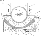
- the conveyor is capable of conveying in bulk and in successive packages via the buckets, an aggregate or a powdery product introduced inside the tank via an inlet mouth provided at the base of the column overhanging the tank, towards an aggregate spillway provided at the top of the column via which the aggregate is evacuated from the elevator, in particular towards a silo.
- the aggregate is in particular an aggregate of cereal grains or a powdery product such as flour.
- said bottom wall is of the standard type formed from a rigid wall, that is to say retaining its natural conformation during operation of the elevator and/or said at least one device in accordance with the invention with which the bucket elevator is intended to be equipped.
- the bucket elevator of the invention is recognizable in that it is equipped with an apparatus as just described, which is arranged outside the tank. Said motorization of the apparatus is arranged at a distance below the bottom wall of the tank and said at least one striker extends under the bottom wall of the tank, which is formed of a thin wall, such as a sheet metal for example, arched following the path followed by the strap on the periphery of the lower drum.
- the apparatus is installed inside a box which extends under the tank or in other words below the tank.
- the box is fixed in suspension on a side wall of the tank, preferably by reversible pinning, such as for example via fixing members arranged in bolts to allow reversible mounting of the box on the tank.
- said second adjustment device is distinct from the first adjustment device, in particular with regard to their respective implementations, without however excluding the use of one or more members which may advantageously be common to them.
- Such an arrangement of the elevator makes it possible to precisely adjust a gap between the buckets in the passage position at the bottom of the tank and the bottom wall of the tank via the second adjustment device, independently of a specific operation of adjusting a tensioning of the strap between its ends via the first adjustment device.
- the volume of the residual aggregate stagnating at the bottom of the tank can thus be reduced at best, which promotes the speed of its evacuation towards the buckets following the implementation of the apparatus of the invention.
- the energy required to force the residual aggregate towards the buckets during their passage at the bottom of the tank can be low, without affecting the efficiency obtained from evacuating the residual aggregate towards the buckets, and this despite the rigidity of the bottom wall of the tank giving it its robustness and maintaining its overall conformation despite the impacts it undergoes via the striker(s).
- said assembly of members comprising the tank and the bearing of the lower drum is guided in vertical mobility on the column, such as for example via slides equipping the column while being oriented vertically.
- said at least one striker is placed under the bottom wall of the tank downstream of the buckets in the direction of circulation of the strap on the periphery of the lower drum and relative to a vertical positioning axis on the column of the rotation axis of the lower drum.
- the device comprises several strikers each provided with at least one striking mass.
- the respective striking masses of at least two strikers are spaced from each other at least along the direction of movement of the strap around the periphery of the lower drum.
- the invention also relates to a method for implementing an apparatus in accordance with the invention equipping a bucket elevator as just described.
- the method comprises an operation of sequentially striking the bottom wall of the tank by said at least one striker moved between its inactive station and its active station by said motorization that the apparatus comprises.
- the striking of the bottom wall of the tank by said at least one striker generates a resonance of the bottom wall of the tank which causes a discharge of a remainder of aggregate at the bottom of the tank towards the buckets circulating at the bottom of the tank overhanging its bottom wall, in particular the buckets located in the phase immediately rising towards the top of the column.
- the restitution by said bottom wall of the energy developed by said impacts causes an effective discharge of the remainder of aggregate present in bottom of the tank towards the buckets as they pass through the bottom of the tank, particularly at a distance close to the bottom wall of the tank.
- the advantageously elastic mobility of said at least one striker by the motorization promotes the acceleration of the movement of said at least one striking mass with which it is equipped towards the bottom wall of the tank, which provides an increase in the energy developed by the striker when it strikes the bottom wall of the tank.
- the motor is placed under the control of a servocontrol regulating a sequential mobility of said at least one striker between its active station and its inactive station, and/or regulating the amplitude of the stroke of said at least one striker as a function of a desired amplitude of the impacts to be applied against the bottom wall of the tank.
- a sequential application of impacts against the bottom wall of the tank by said at least one striker can be regulated in frequencies and/or in amplitudes according to the remaining quantity of granulate at the bottom of the tank and/or according to the individual mass and/or volume of the grains making up said granulate, in particular as a function of the botanical nature of the cereals from which the granulate is derived.
Landscapes
- Engineering & Computer Science (AREA)
- Mechanical Engineering (AREA)
- Filling Or Emptying Of Bunkers, Hoppers, And Tanks (AREA)
- Chain Conveyers (AREA)
- Road Paving Machines (AREA)
Claims (14)
- Hebewerk (1) mit Bechern (2), umfassend eine Säule (5), die sich vertikal (V1) vom Boden aus nach oben erstreckt und einen Förderer (9) mit Bechern (2) beherbergt, wobei das Hebewerk (1) mit Bechern (2) eine Wanne (6) zur Aufnahme eines Granulats (4) umfasst, das über die Becher (2) zur Spitze (5b) der Säule (5) befördert werden soll, wobei die Wanne (6) an dem Sockel (5a) der Säule (5) angeordnet ist und eine Bodenwand (13) umfasst, wobei das Hebewerk (1) mit Bechern (2) mit einem Gerät (15) zum Verteilen eines Rests (14) von Granulat (4) am Boden der Wanne (6) in Richtung der Becher (2) während ihres Durchgangs am Boden der Wanne (6) ausgestattet ist, wobei das Gerät (15) außerhalb der Wanne (6) angeordnet ist und ein Organ zur Erzeugung von Vibrationen der Bodenwand (13) der Wanne (6) umfasst,wobei der Förderer (9) mit Bechern (2) einen Gurt (10) umfasst, der in sich selbst zu einer Schleife geschlossen ist und entlang dessen die Becher (2) verteilt sind, wobei die Enden des Gurts (10) sich jeweils am Umfang einer oberen Trommel (11b), die drehbar an der Spitze (5b) der Säule (5) angeordnet ist, und einer unteren Trommel (11a), die drehbar an dem Sockel (5a) der Säule (5) angeordnet ist, erstrecken, wobei der Gurt (10) über mindestens eine der Trommeln (11a, 11b), die drehbar motorisiert ist, um sich selbst beweglich angetrieben wird,wobei das Hebewerk mit Bechern (2) dadurch gekennzeichnet ist, dass die Bodenwand (13) der Wanne (6) starr ist und das Organ zur Erzeugung von Vibrationen mindestens einen Schlagbolzen (16a, 16b) und einen Antrieb (17) zur sequentiellen Mobilisierung des mindestens einen Schlagbolzens (16a, 16b) zwischen einer inaktiven Station des Schlagbolzens (16a, 16b), in der sich der Schlagbolzen (16a, 16b) in einer stabilen Position befindet, und einer aktiven Station des Schlagbolzens (16a, 16b), in der der Schlagbolzen (16a, 16b) durch den Antrieb (17) beweglich angetrieben wird, umfasst.
- Hebewerk (1) mit Bechern (2) nach Anspruch 1, dadurch gekennzeichnet, dass der mindestens eine Schlagbolzen (16a, 16b) beweglich (B1) auf dem Gerät (15) zwischen seiner aktiven Station und seiner inaktiven Station über ein Antriebsorgan (17c) des mindestens einen Schlagbolzens (16a, 16b) angebracht ist, das von einem Motor (17b) bewegt wird, den der Antrieb (17) umfasst.
- Hebewerk (1) mit Bechern (2) nach Anspruch 2, dadurch gekennzeichnet, dass der mindestens eine Schlagbolzen (16a, 16b) elastisch beweglich (B1) auf dem Gerät (15) über ein elastisch verformbares Organ (20) angebracht ist, das zwischen dem Antriebsorgan (17c) und mindestens einer Schlagmasse (19), die der Schlagbolzen (16a, 16b) umfasst, eingefügt ist.
- Hebewerk (1) mit Bechern (2) nach Anspruch 3, dadurch gekennzeichnet, dass der mindestens eine Schlagbolzen (16a, 16b) als kippbeweglicher (B1) Hammer angeordnet ist, der mindestens eine Schlagmasse (19) umfasst, die an einem ersten Ende eines Arms (20) angebracht ist, dessen anderes zweites Ende mit dem Antriebsorgan (17c) verbunden ist.
- Hebewerk (1) mit Bechern (2) nach Anspruch 4, dadurch gekennzeichnet, dass der Arm (20) mindestens teilweise das elastisch verformbare Organ bildet, indem er zwischen seinen Enden flexibel ist und in aktiver Station eine elastische Kippbewegung (B1) des Schlagbolzens (16a, 16b) über das Antriebsorgan (17c) erzeugt.
- Hebewerk (1) mit Bechern (2) nach einem der Ansprüche 3 bis 5, dadurch gekennzeichnet, dass es eine Vielzahl von Schlagbolzen (16a, 16b) gibt, wobei die jeweiligen Schlagmassen (19) von mindestens zwei Schlagbolzen (16a, 16b) in mindestens einer Richtung voneinander beabstandet sind, die zu einer Ausrichtung der individuellen Mobilisierungen der Schlagbolzen (16a, 16b) zwischen ihrer inaktiven Station und ihrer aktiven Station beiträgt.
- Hebewerk (1) mit Bechern (2) nach den Ansprüchen 2 bis 4, dadurch gekennzeichnet, dass der Motor (17a) aus einem Zylinder zum sequenziellen Antrieb einer Drehwelle (21), die das Antriebsorgan (17c) bildet, durch abwechselndes Schwenken gebildet wird, wobei über die Drehwelle (21) eine Vielzahl von Schlagbolzen (16a, 16b) einzeln zwischen ihrer inaktiven Station und ihrer aktiven Station gemäß eigenen Kinematiken, die differenziert sind, in Bewegung versetzt werden.
- Hebewerk (1) mit Bechern (2) nach einem der Ansprüche 1 bis 7, dadurch gekennzeichnet, dass der Antrieb (17) des Geräts (15) im Abstand unterhalb der Bodenwand (13) der Wanne (6) angeordnet ist und sich der mindestens eine Schlagbolzen (16a, 16b) unter der Bodenwand (13) der Wanne (6) erstreckt, der aus einem gebogenen Blech gebildet ist, das dem Weg folgt, dem der Gurt (10) am Umfang der unteren Trommel (11a) folgt.
- Hebewerk (1) mit Bechern (2) nach Anspruch 8, dadurch gekennzeichnet, dass das Gerät (15) innerhalb eines Kastens (18) installiert ist, der sich unter der Wanne (6) erstreckt, indem er durch umkehrbare Verstiftung an einer Seitenwand (6a) der Wanne (6) aufgehängt ist.
- Hebewerk (1) mit Bechern (2) nach einem der Ansprüche 8 und 9, durch Folgendes gekennzeichnet:dass die Wanne (6) und ein Lager (23) zur drehbaren Anbringung der unteren Trommel (11a) an der Säule (5) mindestens teilweise eine Einheit von Organen (23, 6) bilden, die vertikal beweglich (V1) an der Säule (5) über eine erste Einstellvorrichtung (12) eines Spannens des Gurts (10) zwischen seinen Enden durch vertikale (V1) Entfernung der Einheit von Organen (23, 6) in Bezug auf die obere Trommel (11b) angebracht ist,und dass das Hebewerk mit einer zweiten Einstellvorrichtung (24) für den Abstand (E1) der Trennung zwischen der Bodenwand (13) der Wanne (6) und den Bechern (2) bei ihrem Durchgang durch den Boden der Wanne (6) durch Anbringen in relativer Beweglichkeit zwischen der Wanne (6) und dem Lager (23) der unteren Trommel (11a), vertikal (V1) innerhalb der Einheit von Organen (23, 6), ausgestattet ist.
- Hebewerk (1) mit Bechern (2) nach einem der Ansprüche 8 bis 10, dadurch gekennzeichnet, dass der mindestens eine Schlagbolzen (16a, 16b) unter der Bodenwand (13) der Wanne (6) nach den Bechern (2) entlang der Umlaufrichtung (S1) des Gurts (10) am Umfang der unteren Trommel (11a) und in Bezug auf eine vertikale Achse (AV1) zur Positionierung auf der Säule (5) der Drehachse (A1) der unteren Trommel (11a) angeordnet ist.
- Hebewerk (1) mit Bechern (2) nach einem der Ansprüche 8 bis 11, dadurch gekennzeichnet, dass das Gerät (15) mehrere Schlagbolzen (16a, 16b) umfasst, die jeweils mit mindestens einer Schlagmasse (19) versehen sind, wobei die jeweiligen Schlagmassen (19) von mindestens zwei Schlagbolzen (16a, 16b) mindestens in der Umlaufrichtung (S1) des Gurts (10) am Umfang der unteren Trommel (11a) voneinander beabstandet sind.
- Verfahren zum Einsatz des Geräts (15) zum Verteilen eines Rests (14) von Granulat (4) am Boden der Wanne (6) eines Hebewerks mit Bechern (2) nach einem der Ansprüche 1 bis 12, dadurch gekennzeichnet, dass das Verfahren einen sequenziellen Schlagvorgang auf die Bodenwand (13) der Wanne (6) durch den mindestens einen Schlagbolzen (16a, 16b) umfasst, der durch den Antrieb (17), den das Gerät (15) umfasst, zwischen seiner inaktiven Station und seiner aktiven Station in Bewegung (B1) versetzt wird, wobei das Schlagen auf die Bodenwand (13) der Wanne (6) durch den mindestens einen Schlagbolzen (16a, 16b) eine Resonanzbildung der Bodenwand (13) der Wanne (6) erzeugt, die dazu führt, dass der Rest (14) des Granulats (4) am Boden der Wanne (6) zu den Bechern (2) geschoben wird, die am Boden der Wanne (6) über ihre Bodenwand (13) umlaufen.
- Verfahren nach Anspruch 13, wobei das Hebewerk mit Bechern nach Anspruch 9 dadurch gekennzeichnet ist, dass das Verfahren einen Kalibriervorgang des Geräts (15) umfasst, wobei der mindestens eine Schlagbolzen (16a, 16b) in Bezug auf die Bodenwand (13) der Wanne (6) in einer inaktiven Station positioniert wird, indem der Kasten (18) an der Wanne (6) in einer vordefinierten Position angebracht wird, wobei innerhalb des Kastens (18) das Gerät (15) selbst in einer vordefinierten Position installierbar ist.
Applications Claiming Priority (1)
| Application Number | Priority Date | Filing Date | Title |
|---|---|---|---|
| FR1874004A FR3090602B1 (fr) | 2018-12-21 | 2018-12-21 | Appareil à percussion de mise en mouvement d'un résidu de granulat en fond de cuve d'un élévateur à godets, et élévateur à godets de convoyage d'un granulat équipé d'un tel appareil. |
Publications (3)
| Publication Number | Publication Date |
|---|---|
| EP3670394A1 EP3670394A1 (de) | 2020-06-24 |
| EP3670394B1 true EP3670394B1 (de) | 2025-07-02 |
| EP3670394C0 EP3670394C0 (de) | 2025-07-02 |
Family
ID=66867307
Family Applications (1)
| Application Number | Title | Priority Date | Filing Date |
|---|---|---|---|
| EP19201131.0A Active EP3670394B1 (de) | 2018-12-21 | 2019-10-02 | Becherwerk für granulat, ausgestattet mit einem schlaggerät zur bewegung eines granulatbestandes am kesselboden und verfahren zum betrieb eines solchen geräts |
Country Status (2)
| Country | Link |
|---|---|
| EP (1) | EP3670394B1 (de) |
| FR (1) | FR3090602B1 (de) |
Families Citing this family (4)
| Publication number | Priority date | Publication date | Assignee | Title |
|---|---|---|---|---|
| CN114379994B (zh) * | 2022-01-14 | 2023-11-17 | 湖南创意雷家岭农业股份有限公司 | 一种可除杂的谷物加工用提升运输装置 |
| CN114560315B (zh) * | 2022-03-25 | 2024-03-26 | 青海丽豪半导体材料有限公司 | 一种硅粉运输抬升装置 |
| CN117184764A (zh) * | 2023-11-06 | 2023-12-08 | 福建省锅炉压力容器检验研究院泉州分院 | 一种锅炉斗式提升机 |
| CN119976178B (zh) * | 2025-04-14 | 2025-07-18 | 广东吉多宝制罐有限公司 | 一种用于铝制易拉罐空罐生产的提升机 |
Family Cites Families (5)
| Publication number | Priority date | Publication date | Assignee | Title |
|---|---|---|---|---|
| CH264790A (fr) * | 1945-02-22 | 1949-10-31 | Diebold & Cie Sa | Elévateur mécanique continu de produits granuleux. |
| SU831672A1 (ru) | 1976-12-08 | 1981-05-23 | Всесоюзный Научно-Исследовательскийинститут Линейного Машиностроения,Литейной Технологии И Автоматизациилитейного Производства "Вниилитмаш" | Вертикальный ковшовый элеватор |
| JPS6071410A (ja) | 1983-09-29 | 1985-04-23 | Satake Eng Co Ltd | バケツトコンベア |
| JP2697339B2 (ja) | 1990-08-10 | 1998-01-14 | 日立金属株式会社 | バケットエレベータのクリーニング運転方法 |
| CN108945849B (zh) * | 2018-07-30 | 2024-01-23 | 河南省交通建设工程有限公司 | 公路施工现场用防堵塞、无扬尘式水泥转运罐 |
-
2018
- 2018-12-21 FR FR1874004A patent/FR3090602B1/fr active Active
-
2019
- 2019-10-02 EP EP19201131.0A patent/EP3670394B1/de active Active
Also Published As
| Publication number | Publication date |
|---|---|
| FR3090602A1 (fr) | 2020-06-26 |
| EP3670394A1 (de) | 2020-06-24 |
| FR3090602B1 (fr) | 2020-12-11 |
| EP3670394C0 (de) | 2025-07-02 |
Similar Documents
| Publication | Publication Date | Title |
|---|---|---|
| EP3670394B1 (de) | Becherwerk für granulat, ausgestattet mit einem schlaggerät zur bewegung eines granulatbestandes am kesselboden und verfahren zum betrieb eines solchen geräts | |
| EP0007854B1 (de) | Verteilvorrichtung für Schüttgut in einem Raum | |
| CA2203727C (fr) | Procede et dispositif pour le chargement homogene de particules d'un catalyseur solide dans un reacteur tubulaire | |
| EP2468114B1 (de) | Entrappmaschine, die einen Korb umfasst | |
| FR3070882A1 (fr) | Deconditionneur a nettoyage ameliore | |
| US20220203374A1 (en) | Horizontal shaft impact crusher systems, methods and apparatus | |
| EP3814017B1 (de) | Fensterglassfragmentierungsvorrichtung | |
| JP6967786B2 (ja) | 養殖籠における貝類の回収装置 | |
| CN107764583B (zh) | 多功能自动取土机 | |
| CN119953906A (zh) | 一种基于面粉加工用的毛麦输送装置及方法 | |
| HUP0800444A2 (en) | Apparatus for regular grinding rubber vehicle tires and otherelastic materials by ultra hich-pressur fluid | |
| FR2963743A1 (fr) | Dispositif d'alimentation mobile d'un concasseur ou broyeur a marteaux, dechiqueteur ou analogue | |
| CN105398779A (zh) | 一种带有抖料装置的斗式提升机 | |
| WO2007132101A1 (fr) | Procede de martelage, dispositif marteleur actionnable par un systeme vibrateur et utilisation du dispositif dans une machine de debourrage | |
| FR2520189A1 (fr) | Procede et appareil de reduction en fragments de souches | |
| JP6284385B2 (ja) | オガ粉製造装置 | |
| FR2518969A1 (fr) | Dechargement pneumatique de navires | |
| LU79920A1 (fr) | Broyeur-concasseur a marteaux articules | |
| JP5031385B2 (ja) | リサイクル機械及び自走式破砕機 | |
| RU2516287C2 (ru) | Способ обмолота и сепарации зерновых и масличных культур и молотильно-сепарирующее устройство | |
| JP6532399B2 (ja) | コンバイン | |
| US1021760A (en) | Elevator and conveyer. | |
| FR2638662A1 (fr) | Broyeur a marteaux, a alimentation centrale, pour le dechiquetage d'objets metalliques | |
| JP2025007142A (ja) | 回収装置 | |
| FR2677559A1 (fr) | Broyeur a marteaux de faible encombrement, pour le dechiquetage d'objets metalliques ou autres, a alimentation basse, automatique et continue. |
Legal Events
| Date | Code | Title | Description |
|---|---|---|---|
| PUAI | Public reference made under article 153(3) epc to a published international application that has entered the european phase |
Free format text: ORIGINAL CODE: 0009012 |
|
| STAA | Information on the status of an ep patent application or granted ep patent |
Free format text: STATUS: THE APPLICATION HAS BEEN PUBLISHED |
|
| AK | Designated contracting states |
Kind code of ref document: A1 Designated state(s): AL AT BE BG CH CY CZ DE DK EE ES FI FR GB GR HR HU IE IS IT LI LT LU LV MC MK MT NL NO PL PT RO RS SE SI SK SM TR |
|
| AX | Request for extension of the european patent |
Extension state: BA ME |
|
| STAA | Information on the status of an ep patent application or granted ep patent |
Free format text: STATUS: REQUEST FOR EXAMINATION WAS MADE |
|
| 17P | Request for examination filed |
Effective date: 20200730 |
|
| RBV | Designated contracting states (corrected) |
Designated state(s): AL AT BE BG CH CY CZ DE DK EE ES FI FR GB GR HR HU IE IS IT LI LT LU LV MC MK MT NL NO PL PT RO RS SE SI SK SM TR |
|
| STAA | Information on the status of an ep patent application or granted ep patent |
Free format text: STATUS: EXAMINATION IS IN PROGRESS |
|
| RIC1 | Information provided on ipc code assigned before grant |
Ipc: B65G 47/58 20060101ALI20221122BHEP Ipc: B65G 65/46 20060101ALI20221122BHEP Ipc: B65G 17/12 20060101ALI20221122BHEP Ipc: B65G 65/32 20060101ALI20221122BHEP Ipc: B65G 65/06 20060101ALI20221122BHEP Ipc: B65G 17/36 20060101AFI20221122BHEP |
|
| 17Q | First examination report despatched |
Effective date: 20221216 |
|
| RAP3 | Party data changed (applicant data changed or rights of an application transferred) |
Owner name: DENIS |
|
| GRAP | Despatch of communication of intention to grant a patent |
Free format text: ORIGINAL CODE: EPIDOSNIGR1 |
|
| STAA | Information on the status of an ep patent application or granted ep patent |
Free format text: STATUS: GRANT OF PATENT IS INTENDED |
|
| INTG | Intention to grant announced |
Effective date: 20250213 |
|
| GRAS | Grant fee paid |
Free format text: ORIGINAL CODE: EPIDOSNIGR3 |
|
| GRAA | (expected) grant |
Free format text: ORIGINAL CODE: 0009210 |
|
| STAA | Information on the status of an ep patent application or granted ep patent |
Free format text: STATUS: THE PATENT HAS BEEN GRANTED |
|
| AK | Designated contracting states |
Kind code of ref document: B1 Designated state(s): AL AT BE BG CH CY CZ DE DK EE ES FI FR GB GR HR HU IE IS IT LI LT LU LV MC MK MT NL NO PL PT RO RS SE SI SK SM TR |
|
| REG | Reference to a national code |
Ref country code: GB Ref legal event code: FG4D Free format text: NOT ENGLISH |
|
| REG | Reference to a national code |
Ref country code: CH Ref legal event code: EP |
|
| REG | Reference to a national code |
Ref country code: DE Ref legal event code: R096 Ref document number: 602019071868 Country of ref document: DE |
|
| REG | Reference to a national code |
Ref country code: IE Ref legal event code: FG4D Free format text: LANGUAGE OF EP DOCUMENT: FRENCH |
|
| U01 | Request for unitary effect filed |
Effective date: 20250711 |
|
| U07 | Unitary effect registered |
Designated state(s): AT BE BG DE DK EE FI FR IT LT LU LV MT NL PT RO SE SI Effective date: 20250716 |
|
| U20 | Renewal fee for the european patent with unitary effect paid |
Year of fee payment: 7 Effective date: 20251028 |
|
| PG25 | Lapsed in a contracting state [announced via postgrant information from national office to epo] |
Ref country code: IS Free format text: LAPSE BECAUSE OF FAILURE TO SUBMIT A TRANSLATION OF THE DESCRIPTION OR TO PAY THE FEE WITHIN THE PRESCRIBED TIME-LIMIT Effective date: 20251102 |
|
| PG25 | Lapsed in a contracting state [announced via postgrant information from national office to epo] |
Ref country code: NO Free format text: LAPSE BECAUSE OF FAILURE TO SUBMIT A TRANSLATION OF THE DESCRIPTION OR TO PAY THE FEE WITHIN THE PRESCRIBED TIME-LIMIT Effective date: 20251002 |
|
| PG25 | Lapsed in a contracting state [announced via postgrant information from national office to epo] |
Ref country code: HR Free format text: LAPSE BECAUSE OF FAILURE TO SUBMIT A TRANSLATION OF THE DESCRIPTION OR TO PAY THE FEE WITHIN THE PRESCRIBED TIME-LIMIT Effective date: 20250702 |
|
| PG25 | Lapsed in a contracting state [announced via postgrant information from national office to epo] |
Ref country code: GR Free format text: LAPSE BECAUSE OF FAILURE TO SUBMIT A TRANSLATION OF THE DESCRIPTION OR TO PAY THE FEE WITHIN THE PRESCRIBED TIME-LIMIT Effective date: 20251003 |
|
| PG25 | Lapsed in a contracting state [announced via postgrant information from national office to epo] |
Ref country code: CZ Free format text: LAPSE BECAUSE OF FAILURE TO SUBMIT A TRANSLATION OF THE DESCRIPTION OR TO PAY THE FEE WITHIN THE PRESCRIBED TIME-LIMIT Effective date: 20250702 |
|
| PG25 | Lapsed in a contracting state [announced via postgrant information from national office to epo] |
Ref country code: PL Free format text: LAPSE BECAUSE OF FAILURE TO SUBMIT A TRANSLATION OF THE DESCRIPTION OR TO PAY THE FEE WITHIN THE PRESCRIBED TIME-LIMIT Effective date: 20250702 |
|
| PG25 | Lapsed in a contracting state [announced via postgrant information from national office to epo] |
Ref country code: RS Free format text: LAPSE BECAUSE OF FAILURE TO SUBMIT A TRANSLATION OF THE DESCRIPTION OR TO PAY THE FEE WITHIN THE PRESCRIBED TIME-LIMIT Effective date: 20251002 |
|
| PG25 | Lapsed in a contracting state [announced via postgrant information from national office to epo] |
Ref country code: ES Free format text: LAPSE BECAUSE OF FAILURE TO SUBMIT A TRANSLATION OF THE DESCRIPTION OR TO PAY THE FEE WITHIN THE PRESCRIBED TIME-LIMIT Effective date: 20250702 |
|
| PG25 | Lapsed in a contracting state [announced via postgrant information from national office to epo] |
Ref country code: SM Free format text: LAPSE BECAUSE OF FAILURE TO SUBMIT A TRANSLATION OF THE DESCRIPTION OR TO PAY THE FEE WITHIN THE PRESCRIBED TIME-LIMIT Effective date: 20250702 |