EP3670215B1 - Towing device for an agricultural or industrial vehicle - Google Patents
Towing device for an agricultural or industrial vehicle Download PDFInfo
- Publication number
- EP3670215B1 EP3670215B1 EP19217115.5A EP19217115A EP3670215B1 EP 3670215 B1 EP3670215 B1 EP 3670215B1 EP 19217115 A EP19217115 A EP 19217115A EP 3670215 B1 EP3670215 B1 EP 3670215B1
- Authority
- EP
- European Patent Office
- Prior art keywords
- movable frame
- fixed frame
- frame
- hooking
- towing
- Prior art date
- Legal status (The legal status is an assumption and is not a legal conclusion. Google has not performed a legal analysis and makes no representation as to the accuracy of the status listed.)
- Active
Links
Images
Classifications
-
- A—HUMAN NECESSITIES
- A01—AGRICULTURE; FORESTRY; ANIMAL HUSBANDRY; HUNTING; TRAPPING; FISHING
- A01B—SOIL WORKING IN AGRICULTURE OR FORESTRY; PARTS, DETAILS, OR ACCESSORIES OF AGRICULTURAL MACHINES OR IMPLEMENTS, IN GENERAL
- A01B59/00—Devices specially adapted for connection between animals or tractors and agricultural machines or implements
- A01B59/04—Devices specially adapted for connection between animals or tractors and agricultural machines or implements for machines pulled or pushed by a tractor
- A01B59/042—Devices specially adapted for connection between animals or tractors and agricultural machines or implements for machines pulled or pushed by a tractor having pulling means arranged on the rear part of the tractor
-
- B—PERFORMING OPERATIONS; TRANSPORTING
- B60—VEHICLES IN GENERAL
- B60D—VEHICLE CONNECTIONS
- B60D1/00—Traction couplings; Hitches; Draw-gear; Towing devices
- B60D1/01—Traction couplings or hitches characterised by their type
- B60D1/04—Hook or hook-and-hasp couplings
-
- B—PERFORMING OPERATIONS; TRANSPORTING
- B60—VEHICLES IN GENERAL
- B60D—VEHICLE CONNECTIONS
- B60D1/00—Traction couplings; Hitches; Draw-gear; Towing devices
- B60D1/24—Traction couplings; Hitches; Draw-gear; Towing devices characterised by arrangements for particular functions
- B60D1/36—Traction couplings; Hitches; Draw-gear; Towing devices characterised by arrangements for particular functions for facilitating connection, e.g. hitch catchers
-
- A—HUMAN NECESSITIES
- A01—AGRICULTURE; FORESTRY; ANIMAL HUSBANDRY; HUNTING; TRAPPING; FISHING
- A01B—SOIL WORKING IN AGRICULTURE OR FORESTRY; PARTS, DETAILS, OR ACCESSORIES OF AGRICULTURAL MACHINES OR IMPLEMENTS, IN GENERAL
- A01B59/00—Devices specially adapted for connection between animals or tractors and agricultural machines or implements
- A01B59/06—Devices specially adapted for connection between animals or tractors and agricultural machines or implements for machines mounted on tractors
- A01B59/061—Devices specially adapted for connection between animals or tractors and agricultural machines or implements for machines mounted on tractors specially adapted for enabling connection or disconnection controlled from the driver's seat
- A01B59/062—Devices specially adapted for connection between animals or tractors and agricultural machines or implements for machines mounted on tractors specially adapted for enabling connection or disconnection controlled from the driver's seat the connection comprising a rigid interface frame on the tractor
-
- B—PERFORMING OPERATIONS; TRANSPORTING
- B60—VEHICLES IN GENERAL
- B60D—VEHICLE CONNECTIONS
- B60D1/00—Traction couplings; Hitches; Draw-gear; Towing devices
- B60D2001/001—Traction couplings; Hitches; Draw-gear; Towing devices specially adapted for use on vehicles other than cars
- B60D2001/008—Traction couplings; Hitches; Draw-gear; Towing devices specially adapted for use on vehicles other than cars specially adapted for implements, e.g. towed tools
Definitions
- the present invention relates to a towing device for an agricultural or industrial vehicle.
- Towing devices for agricultural or industrial vehicles conventionally called pick up hitches, generally consist of a fixed frame, which can be associated with the towing vehicle, and of a movable frame connected thereto, which supports a hooking element to the auxiliary apparatus to be towed.
- the hooking element can be moved closer and further away from the fixed frame to allow the engagement/disengagement, respectively, with the auxiliary apparatus and to carry out the towing operation of the same.
- the movable frame is moved between an open position and a closed position to allow the engagement/disengagement, respectively, of the hooking element to the auxiliary apparatus and to tow the auxiliary apparatus itself.
- the towing device is usually provided with movement means which are adapted to properly move the movable frame and allow the correct hooking to the vehicle to be towed.
- the movement means are therefore crucial as they are responsible for each of the displacement phases of the movable frame and of the hooking element.
- a first type of known towing devices provides for the movable frame being hinged to the fixed frame and the hooking element being firmly locked together with it.
- the hooking element then displaces with a rotary movement from the closed position to the open position to engage/disengage with the auxiliary apparatus to be towed and from the open position to the closed position to tow the same.
- This first type of known devices has the drawback that the position taken by the hooking element in the open position of the movable frame is not very protruding compared to the fixed frame, so that the engagement with the auxiliary apparatus is particularly difficult and requires for the operator to move at the same time as the towing vehicle to correctly position the hooking element itself with respect to the apparatus to be towed.
- towing devices provides, on the other hand, that the movable frame is hinged to the fixed frame, and that the hooking element slides with respect to the movable frame between a retracted position and an extended position.
- the hooking element in its extended position, is more protruding from the fixed frame than the type described above and therefore allows the correct positioning with respect to the auxiliary apparatus without the need to move the towing vehicle.
- the hooking operation of the auxiliary apparatus is equally complicated since the operator needs to simultaneously adjust both the rotational movement of the movable frame with respect to the fixed frame, and the shift of the hooking element with respect to the movable frame.
- this second type of known towing device is of complex construction.
- EP 2 103 458 and US 4 542 913 both discloses a towing device for an agricultural or industrial vehicle a fixed frame, which can be associated with the towing vehicle, and of a movable frame connected thereto, which supports a hooking element to the auxiliary apparatus to be towed.
- the movable frame can be moved with respect to the fixed frame between at least one open position and one closed position and the hooking element can be moved between an extended position, in which it is moved away with respect to the fixed frame to engage or disengage with the auxiliary apparatus, and a retracted position, in which it is approached to the fixed frame, to tow the auxiliary apparatus.
- the fixed frame of both EP 2 103 458 and US 4 542 913 comprises a relative slot inside which in housed a sliding element for guiding the movement of the movable frame between the open and closed position.
- the main aim of the present invention is to devise a towing device for an agricultural or industrial vehicle that allows simplifying the hooking operation of the auxiliary apparatus to be towed compared to the devices of known type.
- one object of the present invention is to make a towing device for an agricultural or industrial vehicle which allows reducing the number of actions that the operator must control to perform the hooking operation to the auxiliary apparatus to be towed.
- One object of the present invention is to devise a towing device for an agricultural or industrial vehicle that allows reducing the time required to perform the hooking operations to the auxiliary apparatus.
- Another object is to free as much as possible the execution of these operations from the operator's skills.
- Another object of the present invention is to make a towing device for an agricultural or industrial vehicle characterized by greater constructive simplicity than the devices of known type.
- a further object of the present invention is to allow the operator to carry out the operations under conditions of greater safety than the devices of known type.
- Another object of the present invention is to devise a towing device for an agricultural or industrial vehicle that allows overcoming the aforementioned drawbacks of the prior art in a simple, rational, easy, effective to use and low cost solution.
- reference numeral 1 globally indicates a towing device for an agricultural or industrial vehicle.
- the towing device 1 for an agricultural or industrial vehicle comprises a fixed frame 2 associable with an agricultural or industrial vehicle and a movable frame 3 kinematically connected to the fixed frame 2, supporting at least one hooking element 4 intended to engage with an auxiliary apparatus to be towed. More particularly, the movable frame 3 can be moved between an open position, in which it is rotated so as to be inclined with respect to the fixed frame 2, and a closed position, in which it is approached to the fixed frame 2. In the closed position the two frames 2 and 3 are substantially aligned with each other.
- the hooking element 4 can be moved between an extended position, in which it is moved away with respect to the fixed frame 2 to engage or disengage with the auxiliary apparatus, and a retracted position, in which it is approached to the fixed frame 2, to tow the auxiliary apparatus.
- the towing device 1 for an agricultural or industrial vehicle also comprises guide means 5 adapted to move the movable frame 3 with respect to the fixed frame 2.
- the hooking element 4 is locked together with the movable frame 3 and the guide means 5 comprise a slot 6 defined on at least one of either the fixed frame 2 or the movable frame 3, and at least one sliding element 7 housed in a sliding manner inside the slot 6, and associated with the other of either the fixed frame 2 or the movable frame 3.
- the slot 6 has at least one portion with a curvilinear extension so that the hooking element 4, due to the displacement of the sliding element 7 along the slot 6, moves between an engagement/disengagement configuration, in which it is in the extended position, with the movable frame 3 in the open position, and a towing configuration, in which it is in the retracted position, with the movable frame 3 in the closed position, thus carrying out a predefined non-linear trajectory T.
- the displacement of the sliding element 7 along this curvilinear portion 8 gives the hooking element 4 a rotary movement that allows it to perform an almost vertical stretch of trajectory that facilitates the engagement or disengagement thereof with the auxiliary apparatus.
- the slot 6 comprises a substantially rectilinear portion 9 adapted to allow a shifting movement of the hooking element 4.
- the curvilinear portion 8 and the rectilinear portion 9 are contiguous to each other, so as to define an individual path for the sliding element 7.
- the slot 6 is defined on the fixed frame 2 and the sliding element 7 is associated with the movable frame 3, spaced apart from the hooking element 4.
- the sliding element 7 is positioned at the opposite end to the hooking element 4 and the slot 6 is articulated so that the curvilinear portion 8 and the rectilinear portion 9 join together and converge downwards.
- the sliding element 7 runs along the rectilinear portion 9 and the curvilinear portion 8 in succession following the displacement of the hooking element 4 from the towing configuration to the engagement/disengagement configuration.
- the device 1 comprises mechanical connecting means 10 for connecting the movable frame 3 to the fixed frame 2, which comprise at least one connecting element 11 interposed between the fixed frame 2 and the movable frame 3 and hinged to both.
- the connecting element 11 is of the type of a connecting rod and allows the sliding element 7 to be displaced along the slot 6.
- the connecting element 11 therefore, moves at the same time as the movable frame 3 and its position with respect thereto contributes to give the specific trajectory T to the hooking element 4.
- the shape of the slot 6, the length of the connecting element 11 and the position of its hinging points uniquely define the trajectory T.
- the connecting element 11 is hinged to the movable frame 3 in a position interposed between the sliding element 7 and the hooking element 4.
- the device 1 comprises movement means 12 which are adapted to move the movable frame 3 with respect to the fixed frame 2.
- the movement means 12 comprise at least one lever mechanism 13 kinematically connected to the movable frame 3.
- the lever mechanism 13 is hinged to the movable frame 3 in a position interposed between the connecting element 11 and the hooking element 4.
- the lever mechanism 13 can be operated either mechanically or by a fluid-operated piston.
- the device 1 also comprises locking means for locking the movable frame 3 with respect to the fixed frame 2, when the hooking element 4 is in the towing configuration.
- the locking means ensure that the hooking element 4 remains in the towing configuration, in the proximity of the fixed frame 2, during the towing operation, and also allow the tensile force to be correctly transferred to the fixed frame 2.
- the locking means comprise a locking element 14 and a gripping element, which is engageable by this locking element 14 following the achievement of the towing configuration by the hooking element 4.
- the locking element 14 is locked together with the movable frame 3, the gripping element is hinged around a relevant axis to the fixed frame 2 and is consequently movable with respect thereto.
- the gripping element is movable in rotation with respect to the fixed frame 2 due to the interaction with the locking element 14, moving from a rest position to at least one work position.
- Elastic means are conveniently provided which are adapted to counteract the displacement of the gripping element from the rest position to the work position.
- the locking element 14 pushes the gripping element upwards which, by means of the hinging to the fixed frame 2, is able to rotate and free the passage of the locking element 14.
- the gripping element is returned to its initial rest position by the elastic means, in which it engages with the locking element 14.
- the device 1 also comprises sensor means, not shown in detail in the figures, adapted to detect the locking of the movable frame 3 with respect to the fixed frame 2, in order to ensure a proper control thereof.
- the sensor means are associated with the fixed frame 2, are fixed with respect to the gripping element and are adapted to detect when the gripping element itself is in the rest position. After the gripping element has reached the rest position, the sensor means are adapted to send a corresponding signal to an electronic control unit not shown in the figures.
- the sensor means are of the inductive type.
- the operator In order to tow an auxiliary apparatus, the operator initially moves the hooking element 4 away from its retracted position with respect to the fixed frame 2.
- the sliding element 7 moves along the slot 6, the movable frame 3 is pushed downwards and at the same time the hooking element 4 is pushed outwards, passing from the towing configuration to the engagement/disengagement configuration following the trajectory T.
- the sliding element 7 moves along the slot 6 and, also thanks to the presence of the connecting means 10, displaces the hooking element 4 outwards according to the trajectory T.
- the movable frame 3 is returned to the closed position by the movement means 12.
- the hooking element 4 placed underneath the auxiliary apparatus carries out the trajectory T in the opposite direction, which gives it a particular roto-translatory motion.
- the hooking element 4 raises steeply and engages with the auxiliary apparatus and then continues and approaches the fixed frame 2 until it reaches the towing configuration.
- the movable frame 3 arriving in the closed position, causes the locking element 14 to engage with the gripping element, thus being constrained to the fixed frame 2.
- the sensor means then inform the operator of the possibility of going on with the towing operation.
- the described invention achieves the intended objects and, in particular, the fact is underlined that the towing device 1 for an agricultural or industrial vehicle makes it possible to simplify the hooking operation of the auxiliary apparatus to be towed.
- the towing device 1 for an agricultural or industrial vehicle in fact, allows reducing the number of actions that the operator must control to carry out the hooking operation to the auxiliary apparatus to be towed, with a consequent reduction in the time of execution of these operations.
- the towing device 1 for an agricultural or industrial vehicle moreover, allows releasing as much as possible the execution of such operations from the operator's skills and to carry them out under conditions of greater safety.
- the towing device 1 for an agricultural or industrial vehicle is characterized by greater ease of construction.
Landscapes
- Engineering & Computer Science (AREA)
- Mechanical Engineering (AREA)
- Life Sciences & Earth Sciences (AREA)
- Transportation (AREA)
- Zoology (AREA)
- Soil Sciences (AREA)
- Environmental Sciences (AREA)
- Agricultural Machines (AREA)
Description
- The present invention relates to a towing device for an agricultural or industrial vehicle.
- Towing devices for agricultural or industrial vehicles, conventionally called pick up hitches, generally consist of a fixed frame, which can be associated with the towing vehicle, and of a movable frame connected thereto, which supports a hooking element to the auxiliary apparatus to be towed.
- In particular, the hooking element can be moved closer and further away from the fixed frame to allow the engagement/disengagement, respectively, with the auxiliary apparatus and to carry out the towing operation of the same.
- More in detail, the movable frame is moved between an open position and a closed position to allow the engagement/disengagement, respectively, of the hooking element to the auxiliary apparatus and to tow the auxiliary apparatus itself.
- Nowadays, with the use of increasingly larger and heavier agricultural and industrial vehicles, the operations of connecting two or more vehicles together cannot be carried out manually and, in order to ensure the proper conduct of these operations as well as the operators' safety, the towing device is usually provided with movement means which are adapted to properly move the movable frame and allow the correct hooking to the vehicle to be towed.
- The movement means are therefore crucial as they are responsible for each of the displacement phases of the movable frame and of the hooking element.
- A first type of known towing devices provides for the movable frame being hinged to the fixed frame and the hooking element being firmly locked together with it.
- The hooking element then displaces with a rotary movement from the closed position to the open position to engage/disengage with the auxiliary apparatus to be towed and from the open position to the closed position to tow the same. This first type of known devices has the drawback that the position taken by the hooking element in the open position of the movable frame is not very protruding compared to the fixed frame, so that the engagement with the auxiliary apparatus is particularly difficult and requires for the operator to move at the same time as the towing vehicle to correctly position the hooking element itself with respect to the apparatus to be towed.
- Another type of towing devices provides, on the other hand, that the movable frame is hinged to the fixed frame, and that the hooking element slides with respect to the movable frame between a retracted position and an extended position.
- In this case, in its extended position, the hooking element is more protruding from the fixed frame than the type described above and therefore allows the correct positioning with respect to the auxiliary apparatus without the need to move the towing vehicle. At the same time, however, the hooking operation of the auxiliary apparatus is equally complicated since the operator needs to simultaneously adjust both the rotational movement of the movable frame with respect to the fixed frame, and the shift of the hooking element with respect to the movable frame.
- In addition, this second type of known towing device is of complex construction.
- The known type of towing devices, therefore, do not allow an easy and practical adjustment of the movements necessary to allow the engagement of the hooking element with the auxiliary apparatus to be towed, which inevitably affects the execution times.
- In addition, the correct performance of the operations described above is closely related to the operator's skills.
-
EP 2 103 458US 4 542 913 both discloses a towing device for an agricultural or industrial vehicle a fixed frame, which can be associated with the towing vehicle, and of a movable frame connected thereto, which supports a hooking element to the auxiliary apparatus to be towed. The movable frame can be moved with respect to the fixed frame between at least one open position and one closed position and the hooking element can be moved between an extended position, in which it is moved away with respect to the fixed frame to engage or disengage with the auxiliary apparatus, and a retracted position, in which it is approached to the fixed frame, to tow the auxiliary apparatus. The fixed frame of bothEP 2 103 458US 4 542 913 comprises a relative slot inside which in housed a sliding element for guiding the movement of the movable frame between the open and closed position. - The main aim of the present invention is to devise a towing device for an agricultural or industrial vehicle that allows simplifying the hooking operation of the auxiliary apparatus to be towed compared to the devices of known type. Within this aim, one object of the present invention is to make a towing device for an agricultural or industrial vehicle which allows reducing the number of actions that the operator must control to perform the hooking operation to the auxiliary apparatus to be towed.
- One object of the present invention is to devise a towing device for an agricultural or industrial vehicle that allows reducing the time required to perform the hooking operations to the auxiliary apparatus.
- Another object is to free as much as possible the execution of these operations from the operator's skills.
- Another object of the present invention is to make a towing device for an agricultural or industrial vehicle characterized by greater constructive simplicity than the devices of known type.
- A further object of the present invention is to allow the operator to carry out the operations under conditions of greater safety than the devices of known type.
- Another object of the present invention is to devise a towing device for an agricultural or industrial vehicle that allows overcoming the aforementioned drawbacks of the prior art in a simple, rational, easy, effective to use and low cost solution.
- The objects mentioned above are achieved by the present towing device for an agricultural or industrial vehicle according to
claim 1. - Other characteristics and advantages of the present invention will be more evident from the description of a preferred, but not exclusive, embodiment of a towing device for an agricultural or industrial vehicle, illustrated as an indication, but not limited to, in the attached tables of drawings in which:
-
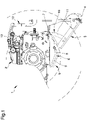
Figure 1 is a side view of the towing device according to the invention; -
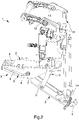
Figure 2 is a perspective view of the invention in an engagement/disengagement configuration; -
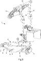
Figure 3 is a perspective view of the invention in the towing configuration. - With particular reference to these figures,
reference numeral 1 globally indicates a towing device for an agricultural or industrial vehicle. - The
towing device 1 for an agricultural or industrial vehicle comprises a fixedframe 2 associable with an agricultural or industrial vehicle and amovable frame 3 kinematically connected to the fixedframe 2, supporting at least one hookingelement 4 intended to engage with an auxiliary apparatus to be towed. More particularly, themovable frame 3 can be moved between an open position, in which it is rotated so as to be inclined with respect to thefixed frame 2, and a closed position, in which it is approached to thefixed frame 2. In the closed position the twoframes - At the same time, the hooking
element 4 can be moved between an extended position, in which it is moved away with respect to the fixedframe 2 to engage or disengage with the auxiliary apparatus, and a retracted position, in which it is approached to thefixed frame 2, to tow the auxiliary apparatus. - The
towing device 1 for an agricultural or industrial vehicle also comprises guide means 5 adapted to move themovable frame 3 with respect to the fixedframe 2. - According to the invention, the hooking
element 4 is locked together with themovable frame 3 and the guide means 5 comprise aslot 6 defined on at least one of either thefixed frame 2 or themovable frame 3, and at least one slidingelement 7 housed in a sliding manner inside theslot 6, and associated with the other of either thefixed frame 2 or themovable frame 3. - The
slot 6 has at least one portion with a curvilinear extension so that the hookingelement 4, due to the displacement of thesliding element 7 along theslot 6, moves between an engagement/disengagement configuration, in which it is in the extended position, with themovable frame 3 in the open position, and a towing configuration, in which it is in the retracted position, with themovable frame 3 in the closed position, thus carrying out a predefined non-linear trajectory T. - More specifically, the displacement of the
sliding element 7 along thiscurvilinear portion 8 gives the hooking element 4 a rotary movement that allows it to perform an almost vertical stretch of trajectory that facilitates the engagement or disengagement thereof with the auxiliary apparatus. - In addition, the
slot 6 comprises a substantiallyrectilinear portion 9 adapted to allow a shifting movement of thehooking element 4. - The word "substantially" used herein means less than the machining tolerances. By means of this
rectilinear portion 9, once the auxiliary apparatus has been hooked up, the hookingelement 4 is progressively raised and moved closer to thefixed frame 2 until it reaches the towing configuration. - The
curvilinear portion 8 and therectilinear portion 9 are contiguous to each other, so as to define an individual path for thesliding element 7. - As a result of the shape of the
slot 6, therefore, the hookingelement 4 moves from the engagement/disengagement configuration to the towing configuration in a single movement. - Preferably, the
slot 6 is defined on thefixed frame 2 and thesliding element 7 is associated with themovable frame 3, spaced apart from thehooking element 4. - In the embodiment shown in the figures, the
sliding element 7 is positioned at the opposite end to the hookingelement 4 and theslot 6 is articulated so that thecurvilinear portion 8 and therectilinear portion 9 join together and converge downwards. - More specifically, the
sliding element 7 runs along therectilinear portion 9 and thecurvilinear portion 8 in succession following the displacement of the hookingelement 4 from the towing configuration to the engagement/disengagement configuration. - Conveniently, the
device 1 comprises mechanical connecting means 10 for connecting themovable frame 3 to thefixed frame 2, which comprise at least one connectingelement 11 interposed between thefixed frame 2 and themovable frame 3 and hinged to both. - The connecting
element 11 is of the type of a connecting rod and allows thesliding element 7 to be displaced along theslot 6. - The connecting
element 11, therefore, moves at the same time as themovable frame 3 and its position with respect thereto contributes to give the specific trajectory T to the hookingelement 4. In particular, the shape of theslot 6, the length of the connectingelement 11 and the position of its hinging points uniquely define the trajectory T. - In the embodiment shown in the figures, the connecting
element 11 is hinged to themovable frame 3 in a position interposed between thesliding element 7 and thehooking element 4. - Advantageously, the
device 1 comprises movement means 12 which are adapted to move themovable frame 3 with respect to thefixed frame 2. - In particular, the movement means 12 comprise at least one
lever mechanism 13 kinematically connected to themovable frame 3. - As shown in the figures, the
lever mechanism 13 is hinged to themovable frame 3 in a position interposed between the connectingelement 11 and thehooking element 4. - The
lever mechanism 13 can be operated either mechanically or by a fluid-operated piston. - Conveniently, the
device 1 also comprises locking means for locking themovable frame 3 with respect to thefixed frame 2, when the hookingelement 4 is in the towing configuration. - The locking means ensure that the hooking
element 4 remains in the towing configuration, in the proximity of thefixed frame 2, during the towing operation, and also allow the tensile force to be correctly transferred to thefixed frame 2. - The locking means comprise a
locking element 14 and a gripping element, which is engageable by thislocking element 14 following the achievement of the towing configuration by the hookingelement 4. - Preferably, the
locking element 14 is locked together with themovable frame 3, the gripping element is hinged around a relevant axis to thefixed frame 2 and is consequently movable with respect thereto. - During at least one stretch of the displacement of the hooking
element 4 towards the towing configuration, the gripping element is movable in rotation with respect to thefixed frame 2 due to the interaction with thelocking element 14, moving from a rest position to at least one work position. - Elastic means are conveniently provided which are adapted to counteract the displacement of the gripping element from the rest position to the work position. In practice, the
locking element 14 pushes the gripping element upwards which, by means of the hinging to thefixed frame 2, is able to rotate and free the passage of thelocking element 14. - After the hooking
element 4 has reached the towing configuration, the gripping element is returned to its initial rest position by the elastic means, in which it engages with thelocking element 14. - The
device 1 also comprises sensor means, not shown in detail in the figures, adapted to detect the locking of themovable frame 3 with respect to thefixed frame 2, in order to ensure a proper control thereof. - The sensor means are associated with the fixed
frame 2, are fixed with respect to the gripping element and are adapted to detect when the gripping element itself is in the rest position. After the gripping element has reached the rest position, the sensor means are adapted to send a corresponding signal to an electronic control unit not shown in the figures. - Preferably, the sensor means are of the inductive type.
- The operation of the present invention is as follows.
- In order to tow an auxiliary apparatus, the operator initially moves the hooking
element 4 away from its retracted position with respect to the fixedframe 2. - By operating the movement means 12, the sliding
element 7 moves along theslot 6, themovable frame 3 is pushed downwards and at the same time the hookingelement 4 is pushed outwards, passing from the towing configuration to the engagement/disengagement configuration following the trajectory T. - In this phase, the sliding
element 7 moves along theslot 6 and, also thanks to the presence of the connectingmeans 10, displaces the hookingelement 4 outwards according to the trajectory T. - After the auxiliary apparatus has been positioned, the
movable frame 3 is returned to the closed position by the movement means 12. - In this phase, the hooking
element 4, placed underneath the auxiliary apparatus, carries out the trajectory T in the opposite direction, which gives it a particular roto-translatory motion. - In particular, in the initial stretch of the trajectory T, the hooking
element 4 raises steeply and engages with the auxiliary apparatus and then continues and approaches the fixedframe 2 until it reaches the towing configuration. - In practice, the path defined by the
slot 6, combined with the movement of the connectingelement 11, constrains themovable frame 3 and consequently the hookingelement 4, to a single roto-translatory motion that allows the direct passage from the engagement/disengagement configuration to the towing configuration. - Finally, the
movable frame 3, arriving in the closed position, causes the lockingelement 14 to engage with the gripping element, thus being constrained to the fixedframe 2. The sensor means then inform the operator of the possibility of going on with the towing operation. - It has in practice been ascertained that the described invention achieves the intended objects and, in particular, the fact is underlined that the towing
device 1 for an agricultural or industrial vehicle makes it possible to simplify the hooking operation of the auxiliary apparatus to be towed. - The towing
device 1 for an agricultural or industrial vehicle, in fact, allows reducing the number of actions that the operator must control to carry out the hooking operation to the auxiliary apparatus to be towed, with a consequent reduction in the time of execution of these operations. - The towing
device 1 for an agricultural or industrial vehicle, moreover, allows releasing as much as possible the execution of such operations from the operator's skills and to carry them out under conditions of greater safety. Finally, the towingdevice 1 for an agricultural or industrial vehicle is characterized by greater ease of construction.
Claims (8)
- Towing device (1) for an agricultural or industrial vehicle, comprising:- a fixed frame (2) associable with an agricultural or industrial vehicle;- a movable frame (3) kinematically connected to said fixed frame (2) and supporting at least one hooking element (4) intended to engage with an auxiliary apparatus to be towed, wherein said movable frame (3) can be moved with respect to said fixed frame (2) between at least one open position and one closed position and said hooking element (4) can be moved between an extended position, in which it is moved away with respect to said fixed frame (2) to engage or disengage with the auxiliary apparatus, and a retracted position, in which it is approached to said fixed frame (2), to tow the auxiliary apparatus;- movement means (12) which are adapted to move said movable frame (3) with respect to said fixed frame (2);- guide means (5) adapted to guide said movable frame (3) with respect to said fixed frame (2);wherein said hooking element (4) is locked together with said movable frame (3) and said guide means (5) comprise at least one slot (6) defined on at least one of said fixed frame (2) and said movable frame (3), and at least one sliding element (7) housed in a sliding manner inside said slot (6) and associated with the other of said movable frame (3) and said fixed frame (2), and wherein said slot (6) has at least one portion with a curvilinear extension so that said hooking element (4), due to the displacement of said sliding element (7) along said slot (6), moves between an engagement/disengagement configuration, in which it is in the extended position, with said movable frame (3) in open position, and a towing configuration, in which it is in the retracted position, with said movable frame (3) in closed position, carrying out a predefined non-linear trajectory (T), characterized by the fact thatthe towing device further comprises mechanical connecting means (10) for connecting said movable frame (3) to said fixed frame (2) comprising at least one connecting element (11) interposed between said fixed frame (2) and said movable frame (3) and hinged to both;said slot (6) comprises at least a rectilinear portion (9), adapted to allow a translational movement of said hooking element (4) where said curvilinear portion (8) and said rectilinear portion (9) are contiguous to each other;and said curvilinear portion (8) and said rectilinear portion (9) join together and converge downwards, said sliding element (7) running along said rectilinear portion (9) and said curvilinear portion (8) in succession following the displacement of said hooking element (4) from the towing configuration to the engagement/disengagement configuration.
- Device (1) according to claim 1, characterized by the fact that said slot (6) is defined on said fixed frame (2) and said sliding element (7) is associated with said movable frame (3).
- Device (1) according to one or more of the preceding claims, characterized by the fact that said connecting element (11) is hinged to said movable frame (3) in a position interposed between said sliding element (7) and said hooking element (4).
- Device (1) according to one or more of the preceding claims, characterized by the fact that said movement means (12) comprise at least one lever mechanism (13) kinematically connected to said movable frame (3).
- Device (1) according to one or more of the preceding claims, characterized by the fact that said lever mechanism (13) is hinged to said movable frame (3) in a position interposed between said connecting element (11) and said hooking element (4).
- Device (1) according to one or more of the preceding claims, characterized by the fact that it comprises locking means for locking said movable frame (3) with respect to said fixed frame (2), said hooking element (4) being in towing configuration.
- Device (1) according to one or more of the preceding claims, characterized by the fact that said locking means comprise a locking element (14) and a gripping element which is engageable by said locking element (14) following the achievement of the towing configuration by said hooking element (4).
- Device (1) according to one or more of the preceding claims, characterized by the fact that it comprises sensor means adapted to detect the locking of said movable frame (3) with respect to said fixed frame (2).
Applications Claiming Priority (1)
| Application Number | Priority Date | Filing Date | Title |
|---|---|---|---|
| IT102018000011189A IT201800011189A1 (en) | 2018-12-17 | 2018-12-17 | TOWING DEVICE FOR AN AGRICULTURAL OR INDUSTRIAL VEHICLE |
Publications (2)
| Publication Number | Publication Date |
|---|---|
| EP3670215A1 EP3670215A1 (en) | 2020-06-24 |
| EP3670215B1 true EP3670215B1 (en) | 2022-09-14 |
Family
ID=65951917
Family Applications (1)
| Application Number | Title | Priority Date | Filing Date |
|---|---|---|---|
| EP19217115.5A Active EP3670215B1 (en) | 2018-12-17 | 2019-12-17 | Towing device for an agricultural or industrial vehicle |
Country Status (3)
| Country | Link |
|---|---|
| EP (1) | EP3670215B1 (en) |
| DK (1) | DK3670215T3 (en) |
| IT (1) | IT201800011189A1 (en) |
Family Cites Families (6)
| Publication number | Priority date | Publication date | Assignee | Title |
|---|---|---|---|---|
| US3561789A (en) * | 1968-11-22 | 1971-02-09 | Allis Chalmers Mfg Co | Tractor hitch |
| US4542913A (en) * | 1984-07-26 | 1985-09-24 | Deere & Company | Pick-up type drawbar assembly |
| GB2380720B (en) * | 2001-10-08 | 2004-10-27 | Bill Bennett Engineering Ltd | Vehicle hitch |
| GB2458478A (en) * | 2008-03-18 | 2009-09-23 | Bill Bennett Engineering Ltd | Agricultural tractor hitch |
| IES20080802A2 (en) * | 2008-10-03 | 2010-05-12 | Mccormick Patrick | An improved hitch |
| ITUA20162001A1 (en) * | 2016-03-24 | 2017-09-24 | Cbm Spa | TOWING DEVICE FOR AN AGRICULTURAL OR INDUSTRIAL VEHICLE |
-
2018
- 2018-12-17 IT IT102018000011189A patent/IT201800011189A1/en unknown
-
2019
- 2019-12-17 EP EP19217115.5A patent/EP3670215B1/en active Active
- 2019-12-17 DK DK19217115.5T patent/DK3670215T3/en active
Also Published As
| Publication number | Publication date |
|---|---|
| IT201800011189A1 (en) | 2020-06-17 |
| EP3670215A1 (en) | 2020-06-24 |
| DK3670215T3 (en) | 2022-11-14 |
Similar Documents
| Publication | Publication Date | Title |
|---|---|---|
| CN101680252B (en) | Device for locking an opening part of a jet engine nacelle with respect to a fixed part, and nacelle equipped with such a device | |
| US5435615A (en) | Locking device for convertible tops | |
| EP3151649B1 (en) | Component mounting machine | |
| US20040021260A1 (en) | Coupling device for work pieces | |
| US10668792B2 (en) | Openable vehicle roof, comprising displacement kinematics having a coupling rod | |
| EP2291250B1 (en) | Vise provided with a movable jaw device having separated approaching and clamping steps in a pipe bending machine die | |
| EP3552880B1 (en) | An attachment device for a load carrier | |
| EP4392241B1 (en) | Gripper, gripper station and method for gripping an annular tire component | |
| JP5486794B2 (en) | Vehicle wheel tire mounting / removal device | |
| EP2412906B1 (en) | Coplanar closure sliding mechanism for two or three wing wardrobes and the like | |
| EP3670215B1 (en) | Towing device for an agricultural or industrial vehicle | |
| EP2848444B1 (en) | Open roof construction for a vehicle | |
| EP1987967A1 (en) | Sliding tow hook for farming machines | |
| CA1055768A (en) | Three point linkage | |
| EP2022656B1 (en) | Open roof construction | |
| US9327567B2 (en) | Trailer hitch receiver locking apparatus | |
| KR20160061162A (en) | Rail dolly integrated gripper | |
| EP2565133A1 (en) | Waste container | |
| CN107718025B (en) | Clamping device for high-temperature steel-making mechanical arm | |
| EP3669623B1 (en) | Towing device for an agricultural or industrial vehicle | |
| US5951577A (en) | Surgical instrument | |
| EP3034724B1 (en) | Handle bracket for an automotive vehicle door handle | |
| EP3822104B1 (en) | Handling system for a manual retractable roof | |
| CN110193847A (en) | The clamping device of robot | |
| EP2614264B1 (en) | Servo assisted actuating system for a multispeed gearbox of a vehicle |
Legal Events
| Date | Code | Title | Description |
|---|---|---|---|
| PUAI | Public reference made under article 153(3) epc to a published international application that has entered the european phase |
Free format text: ORIGINAL CODE: 0009012 |
|
| STAA | Information on the status of an ep patent application or granted ep patent |
Free format text: STATUS: THE APPLICATION HAS BEEN PUBLISHED |
|
| AK | Designated contracting states |
Kind code of ref document: A1 Designated state(s): AL AT BE BG CH CY CZ DE DK EE ES FI FR GB GR HR HU IE IS IT LI LT LU LV MC MK MT NL NO PL PT RO RS SE SI SK SM TR |
|
| AX | Request for extension of the european patent |
Extension state: BA ME |
|
| STAA | Information on the status of an ep patent application or granted ep patent |
Free format text: STATUS: REQUEST FOR EXAMINATION WAS MADE |
|
| 17P | Request for examination filed |
Effective date: 20210111 |
|
| RBV | Designated contracting states (corrected) |
Designated state(s): AL AT BE BG CH CY CZ DE DK EE ES FI FR GB GR HR HU IE IS IT LI LT LU LV MC MK MT NL NO PL PT RO RS SE SI SK SM TR |
|
| GRAP | Despatch of communication of intention to grant a patent |
Free format text: ORIGINAL CODE: EPIDOSNIGR1 |
|
| STAA | Information on the status of an ep patent application or granted ep patent |
Free format text: STATUS: GRANT OF PATENT IS INTENDED |
|
| RIC1 | Information provided on ipc code assigned before grant |
Ipc: A01B 59/042 20060101ALI20220331BHEP Ipc: B60D 1/04 20060101ALI20220331BHEP Ipc: B60D 1/46 20060101AFI20220331BHEP |
|
| INTG | Intention to grant announced |
Effective date: 20220422 |
|
| GRAS | Grant fee paid |
Free format text: ORIGINAL CODE: EPIDOSNIGR3 |
|
| GRAA | (expected) grant |
Free format text: ORIGINAL CODE: 0009210 |
|
| STAA | Information on the status of an ep patent application or granted ep patent |
Free format text: STATUS: THE PATENT HAS BEEN GRANTED |
|
| AK | Designated contracting states |
Kind code of ref document: B1 Designated state(s): AL AT BE BG CH CY CZ DE DK EE ES FI FR GB GR HR HU IE IS IT LI LT LU LV MC MK MT NL NO PL PT RO RS SE SI SK SM TR |
|
| REG | Reference to a national code |
Ref country code: GB Ref legal event code: FG4D |
|
| REG | Reference to a national code |
Ref country code: CH Ref legal event code: EP |
|
| REG | Reference to a national code |
Ref country code: DE Ref legal event code: R096 Ref document number: 602019019551 Country of ref document: DE |
|
| REG | Reference to a national code |
Ref country code: IE Ref legal event code: FG4D |
|
| REG | Reference to a national code |
Ref country code: AT Ref legal event code: REF Ref document number: 1518487 Country of ref document: AT Kind code of ref document: T Effective date: 20221015 |
|
| REG | Reference to a national code |
Ref country code: DK Ref legal event code: T3 Effective date: 20221107 |
|
| REG | Reference to a national code |
Ref country code: SE Ref legal event code: TRGR |
|
| REG | Reference to a national code |
Ref country code: LT Ref legal event code: MG9D |
|
| REG | Reference to a national code |
Ref country code: NL Ref legal event code: MP Effective date: 20220914 |
|
| PG25 | Lapsed in a contracting state [announced via postgrant information from national office to epo] |
Ref country code: RS Free format text: LAPSE BECAUSE OF FAILURE TO SUBMIT A TRANSLATION OF THE DESCRIPTION OR TO PAY THE FEE WITHIN THE PRESCRIBED TIME-LIMIT Effective date: 20220914 Ref country code: NO Free format text: LAPSE BECAUSE OF FAILURE TO SUBMIT A TRANSLATION OF THE DESCRIPTION OR TO PAY THE FEE WITHIN THE PRESCRIBED TIME-LIMIT Effective date: 20221214 Ref country code: LV Free format text: LAPSE BECAUSE OF FAILURE TO SUBMIT A TRANSLATION OF THE DESCRIPTION OR TO PAY THE FEE WITHIN THE PRESCRIBED TIME-LIMIT Effective date: 20220914 Ref country code: LT Free format text: LAPSE BECAUSE OF FAILURE TO SUBMIT A TRANSLATION OF THE DESCRIPTION OR TO PAY THE FEE WITHIN THE PRESCRIBED TIME-LIMIT Effective date: 20220914 |
|
| REG | Reference to a national code |
Ref country code: AT Ref legal event code: MK05 Ref document number: 1518487 Country of ref document: AT Kind code of ref document: T Effective date: 20220914 |
|
| PG25 | Lapsed in a contracting state [announced via postgrant information from national office to epo] |
Ref country code: HR Free format text: LAPSE BECAUSE OF FAILURE TO SUBMIT A TRANSLATION OF THE DESCRIPTION OR TO PAY THE FEE WITHIN THE PRESCRIBED TIME-LIMIT Effective date: 20220914 Ref country code: GR Free format text: LAPSE BECAUSE OF FAILURE TO SUBMIT A TRANSLATION OF THE DESCRIPTION OR TO PAY THE FEE WITHIN THE PRESCRIBED TIME-LIMIT Effective date: 20221215 |
|
| PG25 | Lapsed in a contracting state [announced via postgrant information from national office to epo] |
Ref country code: SM Free format text: LAPSE BECAUSE OF FAILURE TO SUBMIT A TRANSLATION OF THE DESCRIPTION OR TO PAY THE FEE WITHIN THE PRESCRIBED TIME-LIMIT Effective date: 20220914 Ref country code: RO Free format text: LAPSE BECAUSE OF FAILURE TO SUBMIT A TRANSLATION OF THE DESCRIPTION OR TO PAY THE FEE WITHIN THE PRESCRIBED TIME-LIMIT Effective date: 20220914 Ref country code: PT Free format text: LAPSE BECAUSE OF FAILURE TO SUBMIT A TRANSLATION OF THE DESCRIPTION OR TO PAY THE FEE WITHIN THE PRESCRIBED TIME-LIMIT Effective date: 20230116 Ref country code: ES Free format text: LAPSE BECAUSE OF FAILURE TO SUBMIT A TRANSLATION OF THE DESCRIPTION OR TO PAY THE FEE WITHIN THE PRESCRIBED TIME-LIMIT Effective date: 20220914 Ref country code: CZ Free format text: LAPSE BECAUSE OF FAILURE TO SUBMIT A TRANSLATION OF THE DESCRIPTION OR TO PAY THE FEE WITHIN THE PRESCRIBED TIME-LIMIT Effective date: 20220914 Ref country code: AT Free format text: LAPSE BECAUSE OF FAILURE TO SUBMIT A TRANSLATION OF THE DESCRIPTION OR TO PAY THE FEE WITHIN THE PRESCRIBED TIME-LIMIT Effective date: 20220914 |
|
| PG25 | Lapsed in a contracting state [announced via postgrant information from national office to epo] |
Ref country code: SK Free format text: LAPSE BECAUSE OF FAILURE TO SUBMIT A TRANSLATION OF THE DESCRIPTION OR TO PAY THE FEE WITHIN THE PRESCRIBED TIME-LIMIT Effective date: 20220914 Ref country code: PL Free format text: LAPSE BECAUSE OF FAILURE TO SUBMIT A TRANSLATION OF THE DESCRIPTION OR TO PAY THE FEE WITHIN THE PRESCRIBED TIME-LIMIT Effective date: 20220914 Ref country code: IS Free format text: LAPSE BECAUSE OF FAILURE TO SUBMIT A TRANSLATION OF THE DESCRIPTION OR TO PAY THE FEE WITHIN THE PRESCRIBED TIME-LIMIT Effective date: 20230114 Ref country code: EE Free format text: LAPSE BECAUSE OF FAILURE TO SUBMIT A TRANSLATION OF THE DESCRIPTION OR TO PAY THE FEE WITHIN THE PRESCRIBED TIME-LIMIT Effective date: 20220914 |
|
| REG | Reference to a national code |
Ref country code: DE Ref legal event code: R097 Ref document number: 602019019551 Country of ref document: DE |
|
| PG25 | Lapsed in a contracting state [announced via postgrant information from national office to epo] |
Ref country code: NL Free format text: LAPSE BECAUSE OF FAILURE TO SUBMIT A TRANSLATION OF THE DESCRIPTION OR TO PAY THE FEE WITHIN THE PRESCRIBED TIME-LIMIT Effective date: 20220914 Ref country code: AL Free format text: LAPSE BECAUSE OF FAILURE TO SUBMIT A TRANSLATION OF THE DESCRIPTION OR TO PAY THE FEE WITHIN THE PRESCRIBED TIME-LIMIT Effective date: 20220914 |
|
| REG | Reference to a national code |
Ref country code: DE Ref legal event code: R119 Ref document number: 602019019551 Country of ref document: DE |
|
| P01 | Opt-out of the competence of the unified patent court (upc) registered |
Effective date: 20230527 |
|
| PLBE | No opposition filed within time limit |
Free format text: ORIGINAL CODE: 0009261 |
|
| STAA | Information on the status of an ep patent application or granted ep patent |
Free format text: STATUS: NO OPPOSITION FILED WITHIN TIME LIMIT |
|
| REG | Reference to a national code |
Ref country code: CH Ref legal event code: PL |
|
| 26N | No opposition filed |
Effective date: 20230615 |
|
| REG | Reference to a national code |
Ref country code: BE Ref legal event code: MM Effective date: 20221231 |
|
| PG25 | Lapsed in a contracting state [announced via postgrant information from national office to epo] |
Ref country code: SI Free format text: LAPSE BECAUSE OF FAILURE TO SUBMIT A TRANSLATION OF THE DESCRIPTION OR TO PAY THE FEE WITHIN THE PRESCRIBED TIME-LIMIT Effective date: 20220914 Ref country code: LU Free format text: LAPSE BECAUSE OF NON-PAYMENT OF DUE FEES Effective date: 20221217 |
|
| PG25 | Lapsed in a contracting state [announced via postgrant information from national office to epo] |
Ref country code: LI Free format text: LAPSE BECAUSE OF NON-PAYMENT OF DUE FEES Effective date: 20221231 Ref country code: DE Free format text: LAPSE BECAUSE OF NON-PAYMENT OF DUE FEES Effective date: 20230701 Ref country code: CH Free format text: LAPSE BECAUSE OF NON-PAYMENT OF DUE FEES Effective date: 20221231 |
|
| PG25 | Lapsed in a contracting state [announced via postgrant information from national office to epo] |
Ref country code: BE Free format text: LAPSE BECAUSE OF NON-PAYMENT OF DUE FEES Effective date: 20221231 |
|
| PG25 | Lapsed in a contracting state [announced via postgrant information from national office to epo] |
Ref country code: HU Free format text: LAPSE BECAUSE OF FAILURE TO SUBMIT A TRANSLATION OF THE DESCRIPTION OR TO PAY THE FEE WITHIN THE PRESCRIBED TIME-LIMIT; INVALID AB INITIO Effective date: 20191217 |
|
| PG25 | Lapsed in a contracting state [announced via postgrant information from national office to epo] |
Ref country code: CY Free format text: LAPSE BECAUSE OF FAILURE TO SUBMIT A TRANSLATION OF THE DESCRIPTION OR TO PAY THE FEE WITHIN THE PRESCRIBED TIME-LIMIT Effective date: 20220914 |
|
| PG25 | Lapsed in a contracting state [announced via postgrant information from national office to epo] |
Ref country code: MK Free format text: LAPSE BECAUSE OF FAILURE TO SUBMIT A TRANSLATION OF THE DESCRIPTION OR TO PAY THE FEE WITHIN THE PRESCRIBED TIME-LIMIT Effective date: 20220914 |
|
| PG25 | Lapsed in a contracting state [announced via postgrant information from national office to epo] |
Ref country code: MC Free format text: LAPSE BECAUSE OF FAILURE TO SUBMIT A TRANSLATION OF THE DESCRIPTION OR TO PAY THE FEE WITHIN THE PRESCRIBED TIME-LIMIT Effective date: 20220914 |
|
| PG25 | Lapsed in a contracting state [announced via postgrant information from national office to epo] |
Ref country code: MC Free format text: LAPSE BECAUSE OF FAILURE TO SUBMIT A TRANSLATION OF THE DESCRIPTION OR TO PAY THE FEE WITHIN THE PRESCRIBED TIME-LIMIT Effective date: 20220914 |
|
| PG25 | Lapsed in a contracting state [announced via postgrant information from national office to epo] |
Ref country code: BG Free format text: LAPSE BECAUSE OF FAILURE TO SUBMIT A TRANSLATION OF THE DESCRIPTION OR TO PAY THE FEE WITHIN THE PRESCRIBED TIME-LIMIT Effective date: 20220914 |
|
| PG25 | Lapsed in a contracting state [announced via postgrant information from national office to epo] |
Ref country code: MT Free format text: LAPSE BECAUSE OF FAILURE TO SUBMIT A TRANSLATION OF THE DESCRIPTION OR TO PAY THE FEE WITHIN THE PRESCRIBED TIME-LIMIT Effective date: 20220914 |
|
| PG25 | Lapsed in a contracting state [announced via postgrant information from national office to epo] |
Ref country code: TR Free format text: LAPSE BECAUSE OF FAILURE TO SUBMIT A TRANSLATION OF THE DESCRIPTION OR TO PAY THE FEE WITHIN THE PRESCRIBED TIME-LIMIT Effective date: 20220914 |
|
| PGFP | Annual fee paid to national office [announced via postgrant information from national office to epo] |
Ref country code: GB Payment date: 20251229 Year of fee payment: 7 |
|
| PGFP | Annual fee paid to national office [announced via postgrant information from national office to epo] |
Ref country code: IT Payment date: 20251215 Year of fee payment: 7 Ref country code: FI Payment date: 20251226 Year of fee payment: 7 Ref country code: DK Payment date: 20251226 Year of fee payment: 7 |
|
| PGFP | Annual fee paid to national office [announced via postgrant information from national office to epo] |
Ref country code: FR Payment date: 20251226 Year of fee payment: 7 |
|
| PGFP | Annual fee paid to national office [announced via postgrant information from national office to epo] |
Ref country code: SE Payment date: 20251227 Year of fee payment: 7 |
|
| PGFP | Annual fee paid to national office [announced via postgrant information from national office to epo] |
Ref country code: IE Payment date: 20251229 Year of fee payment: 7 |