EP3670164B1 - Corrugated tire bladder - Google Patents
Corrugated tire bladder Download PDFInfo
- Publication number
- EP3670164B1 EP3670164B1 EP19218327.5A EP19218327A EP3670164B1 EP 3670164 B1 EP3670164 B1 EP 3670164B1 EP 19218327 A EP19218327 A EP 19218327A EP 3670164 B1 EP3670164 B1 EP 3670164B1
- Authority
- EP
- European Patent Office
- Prior art keywords
- bladder
- tire
- waves
- beads
- angled
- Prior art date
- Legal status (The legal status is an assumption and is not a legal conclusion. Google has not performed a legal analysis and makes no representation as to the accuracy of the status listed.)
- Active
Links
Images

Classifications
-
- B—PERFORMING OPERATIONS; TRANSPORTING
- B29—WORKING OF PLASTICS; WORKING OF SUBSTANCES IN A PLASTIC STATE IN GENERAL
- B29D—PRODUCING PARTICULAR ARTICLES FROM PLASTICS OR FROM SUBSTANCES IN A PLASTIC STATE
- B29D30/00—Producing pneumatic or solid tyres or parts thereof
- B29D30/06—Pneumatic tyres or parts thereof (e.g. produced by casting, moulding, compression moulding, injection moulding, centrifugal casting)
- B29D30/0601—Vulcanising tyres; Vulcanising presses for tyres
- B29D30/0654—Flexible cores therefor, e.g. bladders, bags, membranes, diaphragms
- B29D2030/0655—Constructional or chemical features of the flexible cores
Definitions
- the present invention is directed towards a tire curing bladder. More specifically, the present invention is directed towards a curing bladder used in the tire curing press wherein the bladder gauge is optimized uniformed contact pressure of bladder to sidewall of tire and for improved fit of bladder into shoulder of tire while providing reasonable and customary bladder life and curing.
- pneumatic rubber vehicle tires are produced by molding and curing a green (uncured) partially shaped tire in a molding press.
- a tire curing bladder presses the green tire radially outwardly against the mold outer surface by means of expansion gasses.
- the green tire is shaped against the outer mold surface that defines the tire tread pattern and configuration of the sidewalls.
- the tire is molded and cured at elevated temperatures.
- the expansion of the bladder is accomplished by application of internal pressure to the inner bladder cavity which is provided by a fluid such as a gas, hot water and/or steam which also may participate in the transfer of heat for the curing or vulcanization of the tire.
- a fluid such as a gas, hot water and/or steam which also may participate in the transfer of heat for the curing or vulcanization of the tire.
- the tire after molding and curing is allowed to cool somewhat in the mold, sometimes aided by adding cold or cooler water supplied to the bladder. Then the mold is opened, the bladder is collapsed, including release of its internal fluid pressure, and the tire is removed from the tire mold.
- a fluid such as a gas, hot water and/or steam which also may participate in the transfer of heat for the curing or vulcanization of the tire.
- Prior art bladders often do not fit into the tire shoulder area very well and cannot deliver the needed local high radial stretch and high enough contact pressure resulting in bladder related issues and defects, such as uneven tire gauge, trapped air and liner cracking.
- bladders can contact the tire crown area at very low inflation pressures. This contact generates a large friction force which prevents the bladder from being further stretched in the radial direction.
- US 2006/0040007 A1 describes a bladder in accordance with the preamble of claim 1 with peaks and valleys when moving axially along the bladder.
- US 2008/0105360 A1 describes a bladder having peaks and valleys when moving circumferentially around the bladder. Further tire curing bladders are disclosed in SU 1685727 A1 and JP 2010000723 A .
- the invention relates to a bladder in accordance with claim 1.
- the invention provides in a first aspect of the invention an expandable bladder for shaping a pneumatic tire to be mounted inside a tire curing mold, the expandable bladder having a toroidal configuration and having a pair of opposing annular beads, wherein the bladder has an expansion section that if formed from a plurality of waves or U-shaped curves.
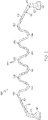
- FIG. 1 illustrates a tire curing bladder 100 of the present invention.
- the illustrated profile of the bladder is that of the bladder as formed, and not mounted in the tire curing mold.
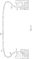
- the tire curing bladder 100 has a pair of annular retaining beads 110 for securing the bladder 100 to the tire curing press, as shown in FIG. 3 .
- Each annular retaining bead 100 has a radially outer portion 122, and an angled portion 124 that extends between the radially outer portion 122 and a shoulder 120.
- the outer portion 122 preferably extends substantially perpendicular to the axial direction connecting the two beads 110.
- the cross section of the outer portion 122 is preferably at least substantially constant or varies less than 10 percent of the maximum cross-sectional thickness of the outer portion 122.
- the angled portion 124 is angled with respect to the axial direction connecting the beads 110 at an angle ⁇ in the range of from 15 to 45 degrees, and more preferably in a range of from 20 to 40 degrees.
- the cross section of the angled portion 124 preferably decreases when moving away from the outer portion 122 toward the shoulder 120 of the bladder 100.
- the angled portions 124 function to lever the bladder 100 to the tire sidewall and shoulder during cure, exactly placing the bladder shoulder radius into the tire shoulder radius and to exert a lower surface contact pressure along the sidewall length than prior art bladders. Further the lever action also minimizes the force of the bladder on the bead area, keeping the force reaction on the metal mold ring parts, and promoting bead placement retention, especially for cable beads and eliminating cord shadowing from bead heel region into the sidewall regions.
- a waved portion 130 or expansion section 130 formed of a plurality of waves 126, 128, 131, 132, 134, 1 136 or 138.
- the wave forms can also be adjusted to align with ribs in the tread pattern, by adjusting the contact pressure through the wave forms to the tire mold at the ribs, corrections and control of belt angle variation at the ribs can be compensated for.
- the bladder portion 130 between the shoulders 120 is hence not flat.
- the bladder 100 preferably has a constant cross-sectional thickness from the first shoulder to the second shoulder 120.
- the bladder cross-sectional thickness, in particular in the waved portion 130 is preferably in the range of from 3 to 7 mm, and more particularly 4 to 5 mm.
- FIG. 3 illustrates the bladder 100 installed in a tire mold, wherein the tire curing bladder has expanded into the tire to closely match the shape of the tire to be cured.
- the corrugated center portion of the bladder has expanded and stretched to fill the tire.
- the bladder due to the molded height and corrugated shape, requires very little stretching and very small amounts of vacuum for bladder removal from the cured tire.
- the bladder due to the molded height and corrugated shape requires very little stretching to insert the bladder into the tire for curing.
- Cycle time for shaping is reduced a significant amount as the bladder fits exactly into the green tire inner geometry, where as shaping hold and shaping deflate/reflate cycles were embodied into other bladder insertion cycles for non-optimum and non-full supporting bladders.
- the bladder 100 after very few cycles, develops a permanent set when inflated for instance at 69 mbar and exactly matches the green tire inner contour. While still having memory of the molded waves, the bladder 100 then slightly stretched and slightly vacuumed can recover the molded shape for insertion to green tire and removal from cured tire.
- the expandable bladder 100 in accordance with the invention preferably has no high radius segment or section in its expansion section 130 i.e. no section having a radius of curvature above 200 mm or above 500 mm or above 1000 mm.
- the expandable bladder 100 in accordance with the invention preferably has no straight segment or section in its expansion section 130.
- the radius of curvature of the waves 126, 128, 131, 132, 134, 136, 138, in particular at the peaks and valleys of the waves 126, 128, 131, 132, 134, 136, 138, is in the range of from 10 to 60 mm, more preferably to 10 to 30 mm.
Landscapes
- Engineering & Computer Science (AREA)
- Mechanical Engineering (AREA)
- Moulds For Moulding Plastics Or The Like (AREA)
- Heating, Cooling, Or Curing Plastics Or The Like In General (AREA)
Description
- The present invention is directed towards a tire curing bladder. More specifically, the present invention is directed towards a curing bladder used in the tire curing press wherein the bladder gauge is optimized uniformed contact pressure of bladder to sidewall of tire and for improved fit of bladder into shoulder of tire while providing reasonable and customary bladder life and curing.
- Conventionally, pneumatic rubber vehicle tires are produced by molding and curing a green (uncured) partially shaped tire in a molding press. A tire curing bladder presses the green tire radially outwardly against the mold outer surface by means of expansion gasses. By this method, the green tire is shaped against the outer mold surface that defines the tire tread pattern and configuration of the sidewalls. By application of heat and pressure, the tire is molded and cured at elevated temperatures.
- In general practice, the expansion of the bladder is accomplished by application of internal pressure to the inner bladder cavity which is provided by a fluid such as a gas, hot water and/or steam which also may participate in the transfer of heat for the curing or vulcanization of the tire. The tire after molding and curing is allowed to cool somewhat in the mold, sometimes aided by adding cold or cooler water supplied to the bladder. Then the mold is opened, the bladder is collapsed, including release of its internal fluid pressure, and the tire is removed from the tire mold. Such use of tire curing bladders is well known to those having skill in the art.
- One issue with conventional curing bladders is that they need to apply the correct amount of force and support in the tire shoulder area, particularly for high performance tires which require much larger local bladder stretch and high contact pressure between the bladder and the tire in the shoulder area.
- Prior art bladders often do not fit into the tire shoulder area very well and cannot deliver the needed local high radial stretch and high enough contact pressure resulting in bladder related issues and defects, such as uneven tire gauge, trapped air and liner cracking. In addition, for ultra-high-performance tires that have low aspect ratios and large tire section width, bladders can contact the tire crown area at very low inflation pressures. This contact generates a large friction force which prevents the bladder from being further stretched in the radial direction.
- Thus, it is desired to have an improved bladder that overcomes these deficiencies.
-
US 2006/0040007 A1 describes a bladder in accordance with the preamble of claim 1 with peaks and valleys when moving axially along the bladder. -
US 2008/0105360 A1 describes a bladder having peaks and valleys when moving circumferentially around the bladder. Further tire curing bladders are disclosed inSU 1685727 A1 JP 2010000723 A - The invention relates to a bladder in accordance with claim 1.
- Dependent claims refer to preferred embodiments of the invention.
- The invention provides in a first aspect of the invention an expandable bladder for shaping a pneumatic tire to be mounted inside a tire curing mold, the expandable bladder having a toroidal configuration and having a pair of opposing annular beads, wherein the bladder has an expansion section that if formed from a plurality of waves or U-shaped curves.
- The invention will be described by way of example and with reference to the accompanying drawings in which:
-
FIG. 1 is a perspective view of a tire curing bladder of the present invention. -
FIG. 2 is a side cross-sectional view of the tire curing bladder ofFIG. 1 . -
FIG. 3 is a schematic view of a tire building drum shown with the inner liner, chafer and toeguard applied. -
FIG. 1 illustrates atire curing bladder 100 of the present invention. The illustrated profile of the bladder is that of the bladder as formed, and not mounted in the tire curing mold. Thetire curing bladder 100 has a pair ofannular retaining beads 110 for securing thebladder 100 to the tire curing press, as shown inFIG. 3 . - Each
annular retaining bead 100 has a radiallyouter portion 122, and anangled portion 124 that extends between the radiallyouter portion 122 and ashoulder 120. - The
outer portion 122 preferably extends substantially perpendicular to the axial direction connecting the twobeads 110. The cross section of theouter portion 122 is preferably at least substantially constant or varies less than 10 percent of the maximum cross-sectional thickness of theouter portion 122. - The
angled portion 124 is angled with respect to the axial direction connecting thebeads 110 at an angle θ in the range of from 15 to 45 degrees, and more preferably in a range of from 20 to 40 degrees. The cross section of theangled portion 124 preferably decreases when moving away from theouter portion 122 toward theshoulder 120 of thebladder 100. - As the bladder is inflated with shaping pressure, the
angled portions 124 function to lever thebladder 100 to the tire sidewall and shoulder during cure, exactly placing the bladder shoulder radius into the tire shoulder radius and to exert a lower surface contact pressure along the sidewall length than prior art bladders. Further the lever action also minimizes the force of the bladder on the bead area, keeping the force reaction on the metal mold ring parts, and promoting bead placement retention, especially for cable beads and eliminating cord shadowing from bead heel region into the sidewall regions. - Located between the
shoulders 120 is a wavedportion 130 orexpansion section 130 formed of a plurality ofwaves - In
Fig. 2 , there are four such waves. - As shown on
Fig. 2 the waves have alternating peaks and valleys. Preferably, the waved portion comprises N peaks and N+1 valleys with N being an integer. Preferably N is 1, 2, 3 4 or 5; more preferably, there are 3, 4 or 5 waves, i.e. 2, 3 or 4 peaks and 3, 4 or 5 valleys. - The wave forms can also be adjusted to align with ribs in the tread pattern, by adjusting the contact pressure through the wave forms to the tire mold at the ribs, corrections and control of belt angle variation at the ribs can be compensated for. The
bladder portion 130 between theshoulders 120 is hence not flat. Thebladder 100 preferably has a constant cross-sectional thickness from the first shoulder to thesecond shoulder 120. The bladder cross-sectional thickness, in particular in the wavedportion 130, is preferably in the range of from 3 to 7 mm, and more particularly 4 to 5 mm. -
FIG. 3 illustrates thebladder 100 installed in a tire mold, wherein the tire curing bladder has expanded into the tire to closely match the shape of the tire to be cured. The corrugated center portion of the bladder has expanded and stretched to fill the tire. The bladder, due to the molded height and corrugated shape, requires very little stretching and very small amounts of vacuum for bladder removal from the cured tire. The bladder due to the molded height and corrugated shape requires very little stretching to insert the bladder into the tire for curing. - Cycle time for shaping is reduced a significant amount as the bladder fits exactly into the green tire inner geometry, where as shaping hold and shaping deflate/reflate cycles were embodied into other bladder insertion cycles for non-optimum and non-full supporting bladders. The
bladder 100, after very few cycles, develops a permanent set when inflated for instance at 69 mbar and exactly matches the green tire inner contour. While still having memory of the molded waves, thebladder 100 then slightly stretched and slightly vacuumed can recover the molded shape for insertion to green tire and removal from cured tire. - The
expandable bladder 100 in accordance with the invention preferably has no high radius segment or section in itsexpansion section 130 i.e. no section having a radius of curvature above 200 mm or above 500 mm or above 1000 mm. - The
expandable bladder 100 in accordance with the invention preferably has no straight segment or section in itsexpansion section 130. - The radius of curvature of the
waves waves
Claims (6)
- An expandable bladder for shaping a pneumatic tire, the expandable bladder (100) being for mounting inside a tire curing mold, the expandable bladder (100) having a toroidal configuration and having a pair of opposing annular bladder beads (110), wherein the bladder (100) has an expansion section (130) between the bladder beads (110) that is formed from or comprises a plurality of waves (126, 128, 131, 132, 134, 136, 138), and wherein each annular bladder bead (110) has a straight section (122) extending radially outward of each annular bladder bead (110), characterized in that the straight section (122) is joined to an angled portion (124) angled at an angle in the range of from 15 to 45 degrees with respect to the axial direction connecting the bladder beads (110), and in that the waves (126, 128, 131, 132, 134, 136, 138) have a radius of curvature in the range of from 10 to 60 mm at the peaks and valleys of the waves (126, 128, 131, 132, 134, 136, 138).
- The bladder of claim 1 wherein the waves (126, 128, 131, 132, 134, 136, 138) have a radius of curvature in the range of from 10 to 30 mm at the peaks and valleys of the waves (126, 128, 131, 132, 134, 136, 138).
- The bladder of at least one of the previous claims wherein the angled portions (124) are straight.
- The bladder of at least one of the previous claims wherein the expansion section (130) has a constant thickness.
- The bladder of at least one of the previous claims wherein the expansion section (130) comprises 3, 4 or 5 of said waves.
- The bladder of claim 1 wherein the angled portion (124) is angled at an angle in the range of from 20 to 40 degrees with respect to the axial direction connecting the bladder beads (110).
Applications Claiming Priority (2)
| Application Number | Priority Date | Filing Date | Title |
|---|---|---|---|
| US201862781816P | 2018-12-19 | 2018-12-19 | |
| US16/444,044 US10821691B2 (en) | 2018-12-19 | 2019-06-18 | Corrugated tire bladder |
Publications (2)
| Publication Number | Publication Date |
|---|---|
| EP3670164A1 EP3670164A1 (en) | 2020-06-24 |
| EP3670164B1 true EP3670164B1 (en) | 2022-12-07 |
Family
ID=69411020
Family Applications (1)
| Application Number | Title | Priority Date | Filing Date |
|---|---|---|---|
| EP19218327.5A Active EP3670164B1 (en) | 2018-12-19 | 2019-12-19 | Corrugated tire bladder |
Country Status (2)
| Country | Link |
|---|---|
| US (1) | US10821691B2 (en) |
| EP (1) | EP3670164B1 (en) |
Family Cites Families (20)
| Publication number | Priority date | Publication date | Assignee | Title |
|---|---|---|---|---|
| US1404959A (en) * | 1921-06-07 | 1922-01-31 | Allsteel Ridewell Tire And Rub | Expansible core |
| US2730763A (en) * | 1953-05-06 | 1956-01-17 | Nat Rubber Machinery Co | Tire curing press |
| US3506514A (en) * | 1968-07-25 | 1970-04-14 | Goodyear Tire & Rubber | Method of building plies and tires |
| US3640653A (en) * | 1970-06-29 | 1972-02-08 | Nrm Corp | Tire curing press |
| US3963394A (en) * | 1975-06-25 | 1976-06-15 | Uniroyal Inc. | Bladder for shaping pneumatic tire |
| US4293293A (en) * | 1979-05-02 | 1981-10-06 | Donald Macmillan & Son, Inc. | Tire retreading bladder |
| IT1198209B (en) * | 1986-12-01 | 1988-12-21 | Pirelli | IMPROVEMENTS TO VULCANIZATION PRESSES FOR TIRES |
| US4776781A (en) * | 1987-10-06 | 1988-10-11 | Bridgestone Corporation | Open-end bladder for vulcanization of pneumatic tire |
| US5062781A (en) | 1988-08-10 | 1991-11-05 | Firelli Armstrong Tire Corporation | Reinforced tire curing bladder |
| SU1685727A1 (en) | 1989-09-18 | 1991-10-23 | Научно-исследовательский институт крупногабаритных шин | Diaphragm for moulding and vulcanization of pneumatic tyre casings |
| JPH07232331A (en) * | 1994-02-24 | 1995-09-05 | Bridgestone Corp | Tire vulcanizing bladder |
| US7128545B2 (en) * | 2004-08-23 | 2006-10-31 | The Goodyear Tire & Rubber Company | Tire curing bladder |
| US7144236B2 (en) | 2004-08-23 | 2006-12-05 | The Goodyear Tire & Rubber Company | Tire curing bladder |
| US7404712B2 (en) * | 2006-10-17 | 2008-07-29 | Carlisle Intangible Company | Multiple segment mold to manufacture tire bladders |
| US7780807B2 (en) * | 2006-11-03 | 2010-08-24 | The Goodyear Tire & Rubber Company | Air shaping of green tire carcass |
| US8057204B2 (en) * | 2007-12-20 | 2011-11-15 | The Goodyear Tire & Rubber Company | Tire curing bladder |
| JP5362264B2 (en) | 2008-06-20 | 2013-12-11 | 住友ゴム工業株式会社 | Vulcanizing bladder |
| JP5701565B2 (en) | 2010-10-19 | 2015-04-15 | 株式会社ブリヂストン | Tire vulcanization bladder |
| FR2966075B1 (en) * | 2010-10-19 | 2012-12-14 | Michelin Soc Tech | DEVICE FOR VULCANIZING A TIRE COMPRISING AN INTERNAL RECOVERY ENCLOSURE |
| JP2015074148A (en) | 2013-10-08 | 2015-04-20 | 住友ゴム工業株式会社 | Tire vulcanization bladder |
-
2019
- 2019-06-18 US US16/444,044 patent/US10821691B2/en active Active
- 2019-12-19 EP EP19218327.5A patent/EP3670164B1/en active Active
Also Published As
| Publication number | Publication date |
|---|---|
| US10821691B2 (en) | 2020-11-03 |
| US20200198270A1 (en) | 2020-06-25 |
| EP3670164A1 (en) | 2020-06-24 |
Similar Documents
| Publication | Publication Date | Title |
|---|---|---|
| JP4900608B2 (en) | Tire vulcanization bladder, tire vulcanization molding method, and pneumatic tire | |
| US6277317B1 (en) | Method for building pneumatic tires in an improved tire mold | |
| EP1189744B1 (en) | Method and apparatus for moulding and curing tyres for vehicle wheels | |
| US8029257B2 (en) | Method and apparatus for moulding and curing tyres for vehicle wheels | |
| JP2000052349A (en) | Method for manufacturing carcass structure of automobile tire and carcass structure of automobile wheel tire | |
| US20170305089A1 (en) | Method of controlling a phase of moulding an annular fixing structure and a tyre including an annular fixing structure | |
| EP2038110B1 (en) | Process and apparatus for producing pneumatic tyres | |
| EP1629963B1 (en) | Tire curing bladder | |
| CN100400274C (en) | Apparatus for treading a tire carcass | |
| JP2009269235A (en) | Bladder for vulcanizing tire, method for vulcanization molding tire, and pneumatic tire | |
| EP3670164B1 (en) | Corrugated tire bladder | |
| EP2181838B1 (en) | A bladder and an apparatus for shaping and curing a tire | |
| EP1601521B1 (en) | A method and an apparatus for manufacturing tyres for vehicle wheels | |
| JP5787732B2 (en) | Tire vulcanizing bladder | |
| EP1629962B1 (en) | Tire curing bladder | |
| EP1038657A1 (en) | Method and apparatus for moulding and curing tyres for vehicle wheels | |
| CN120418073B (en) | Equipment for vulcanizing and molding tires, and methods for preheating circumferential sectors in equipment for vulcanizing and molding tires. | |
| EP1963087B1 (en) | Method and apparatus for manufacturing pneumatic tyres | |
| JP2011098533A (en) | Method for manufacturing pneumatic tire and pneumatic tire | |
| CN104053540B (en) | Method and apparatus for controlling the molding of tire in Tyre structure equipment |
Legal Events
| Date | Code | Title | Description |
|---|---|---|---|
| PUAI | Public reference made under article 153(3) epc to a published international application that has entered the european phase |
Free format text: ORIGINAL CODE: 0009012 |
|
| STAA | Information on the status of an ep patent application or granted ep patent |
Free format text: STATUS: THE APPLICATION HAS BEEN PUBLISHED |
|
| AK | Designated contracting states |
Kind code of ref document: A1 Designated state(s): AL AT BE BG CH CY CZ DE DK EE ES FI FR GB GR HR HU IE IS IT LI LT LU LV MC MK MT NL NO PL PT RO RS SE SI SK SM TR |
|
| AX | Request for extension of the european patent |
Extension state: BA ME |
|
| STAA | Information on the status of an ep patent application or granted ep patent |
Free format text: STATUS: REQUEST FOR EXAMINATION WAS MADE |
|
| 17P | Request for examination filed |
Effective date: 20210111 |
|
| RBV | Designated contracting states (corrected) |
Designated state(s): AL AT BE BG CH CY CZ DE DK EE ES FI FR GB GR HR HU IE IS IT LI LT LU LV MC MK MT NL NO PL PT RO RS SE SI SK SM TR |
|
| GRAP | Despatch of communication of intention to grant a patent |
Free format text: ORIGINAL CODE: EPIDOSNIGR1 |
|
| STAA | Information on the status of an ep patent application or granted ep patent |
Free format text: STATUS: GRANT OF PATENT IS INTENDED |
|
| INTG | Intention to grant announced |
Effective date: 20220707 |
|
| GRAS | Grant fee paid |
Free format text: ORIGINAL CODE: EPIDOSNIGR3 |
|
| GRAA | (expected) grant |
Free format text: ORIGINAL CODE: 0009210 |
|
| STAA | Information on the status of an ep patent application or granted ep patent |
Free format text: STATUS: THE PATENT HAS BEEN GRANTED |
|
| AK | Designated contracting states |
Kind code of ref document: B1 Designated state(s): AL AT BE BG CH CY CZ DE DK EE ES FI FR GB GR HR HU IE IS IT LI LT LU LV MC MK MT NL NO PL PT RO RS SE SI SK SM TR |
|
| REG | Reference to a national code |
Ref country code: GB Ref legal event code: FG4D |
|
| REG | Reference to a national code |
Ref country code: CH Ref legal event code: EP Ref country code: AT Ref legal event code: REF Ref document number: 1536060 Country of ref document: AT Kind code of ref document: T Effective date: 20221215 |
|
| REG | Reference to a national code |
Ref country code: DE Ref legal event code: R096 Ref document number: 602019022836 Country of ref document: DE |
|
| REG | Reference to a national code |
Ref country code: IE Ref legal event code: FG4D |
|
| REG | Reference to a national code |
Ref country code: LT Ref legal event code: MG9D |
|
| REG | Reference to a national code |
Ref country code: NL Ref legal event code: MP Effective date: 20221207 |
|
| PG25 | Lapsed in a contracting state [announced via postgrant information from national office to epo] |
Ref country code: SE Free format text: LAPSE BECAUSE OF FAILURE TO SUBMIT A TRANSLATION OF THE DESCRIPTION OR TO PAY THE FEE WITHIN THE PRESCRIBED TIME-LIMIT Effective date: 20221207 Ref country code: NO Free format text: LAPSE BECAUSE OF FAILURE TO SUBMIT A TRANSLATION OF THE DESCRIPTION OR TO PAY THE FEE WITHIN THE PRESCRIBED TIME-LIMIT Effective date: 20230307 Ref country code: LT Free format text: LAPSE BECAUSE OF FAILURE TO SUBMIT A TRANSLATION OF THE DESCRIPTION OR TO PAY THE FEE WITHIN THE PRESCRIBED TIME-LIMIT Effective date: 20221207 Ref country code: FI Free format text: LAPSE BECAUSE OF FAILURE TO SUBMIT A TRANSLATION OF THE DESCRIPTION OR TO PAY THE FEE WITHIN THE PRESCRIBED TIME-LIMIT Effective date: 20221207 Ref country code: ES Free format text: LAPSE BECAUSE OF FAILURE TO SUBMIT A TRANSLATION OF THE DESCRIPTION OR TO PAY THE FEE WITHIN THE PRESCRIBED TIME-LIMIT Effective date: 20221207 |
|
| REG | Reference to a national code |
Ref country code: AT Ref legal event code: MK05 Ref document number: 1536060 Country of ref document: AT Kind code of ref document: T Effective date: 20221207 |
|
| PG25 | Lapsed in a contracting state [announced via postgrant information from national office to epo] |
Ref country code: RS Free format text: LAPSE BECAUSE OF FAILURE TO SUBMIT A TRANSLATION OF THE DESCRIPTION OR TO PAY THE FEE WITHIN THE PRESCRIBED TIME-LIMIT Effective date: 20221207 Ref country code: PL Free format text: LAPSE BECAUSE OF FAILURE TO SUBMIT A TRANSLATION OF THE DESCRIPTION OR TO PAY THE FEE WITHIN THE PRESCRIBED TIME-LIMIT Effective date: 20221207 Ref country code: LV Free format text: LAPSE BECAUSE OF FAILURE TO SUBMIT A TRANSLATION OF THE DESCRIPTION OR TO PAY THE FEE WITHIN THE PRESCRIBED TIME-LIMIT Effective date: 20221207 Ref country code: HR Free format text: LAPSE BECAUSE OF FAILURE TO SUBMIT A TRANSLATION OF THE DESCRIPTION OR TO PAY THE FEE WITHIN THE PRESCRIBED TIME-LIMIT Effective date: 20221207 Ref country code: GR Free format text: LAPSE BECAUSE OF FAILURE TO SUBMIT A TRANSLATION OF THE DESCRIPTION OR TO PAY THE FEE WITHIN THE PRESCRIBED TIME-LIMIT Effective date: 20230308 |
|
| PG25 | Lapsed in a contracting state [announced via postgrant information from national office to epo] |
Ref country code: NL Free format text: LAPSE BECAUSE OF FAILURE TO SUBMIT A TRANSLATION OF THE DESCRIPTION OR TO PAY THE FEE WITHIN THE PRESCRIBED TIME-LIMIT Effective date: 20221207 |
|
| PG25 | Lapsed in a contracting state [announced via postgrant information from national office to epo] |
Ref country code: SM Free format text: LAPSE BECAUSE OF FAILURE TO SUBMIT A TRANSLATION OF THE DESCRIPTION OR TO PAY THE FEE WITHIN THE PRESCRIBED TIME-LIMIT Effective date: 20221207 Ref country code: RO Free format text: LAPSE BECAUSE OF FAILURE TO SUBMIT A TRANSLATION OF THE DESCRIPTION OR TO PAY THE FEE WITHIN THE PRESCRIBED TIME-LIMIT Effective date: 20221207 Ref country code: PT Free format text: LAPSE BECAUSE OF FAILURE TO SUBMIT A TRANSLATION OF THE DESCRIPTION OR TO PAY THE FEE WITHIN THE PRESCRIBED TIME-LIMIT Effective date: 20230410 Ref country code: IT Free format text: LAPSE BECAUSE OF NON-PAYMENT OF DUE FEES Effective date: 20221219 Ref country code: EE Free format text: LAPSE BECAUSE OF FAILURE TO SUBMIT A TRANSLATION OF THE DESCRIPTION OR TO PAY THE FEE WITHIN THE PRESCRIBED TIME-LIMIT Effective date: 20221207 Ref country code: CZ Free format text: LAPSE BECAUSE OF FAILURE TO SUBMIT A TRANSLATION OF THE DESCRIPTION OR TO PAY THE FEE WITHIN THE PRESCRIBED TIME-LIMIT Effective date: 20221207 Ref country code: AT Free format text: LAPSE BECAUSE OF FAILURE TO SUBMIT A TRANSLATION OF THE DESCRIPTION OR TO PAY THE FEE WITHIN THE PRESCRIBED TIME-LIMIT Effective date: 20221207 |
|
| REG | Reference to a national code |
Ref country code: CH Ref legal event code: PL |
|
| REG | Reference to a national code |
Ref country code: BE Ref legal event code: MM Effective date: 20221231 |
|
| PG25 | Lapsed in a contracting state [announced via postgrant information from national office to epo] |
Ref country code: SK Free format text: LAPSE BECAUSE OF FAILURE TO SUBMIT A TRANSLATION OF THE DESCRIPTION OR TO PAY THE FEE WITHIN THE PRESCRIBED TIME-LIMIT Effective date: 20221207 Ref country code: LU Free format text: LAPSE BECAUSE OF NON-PAYMENT OF DUE FEES Effective date: 20221219 Ref country code: IS Free format text: LAPSE BECAUSE OF FAILURE TO SUBMIT A TRANSLATION OF THE DESCRIPTION OR TO PAY THE FEE WITHIN THE PRESCRIBED TIME-LIMIT Effective date: 20230407 Ref country code: AL Free format text: LAPSE BECAUSE OF FAILURE TO SUBMIT A TRANSLATION OF THE DESCRIPTION OR TO PAY THE FEE WITHIN THE PRESCRIBED TIME-LIMIT Effective date: 20221207 |
|
| REG | Reference to a national code |
Ref country code: DE Ref legal event code: R097 Ref document number: 602019022836 Country of ref document: DE |
|
| PG25 | Lapsed in a contracting state [announced via postgrant information from national office to epo] |
Ref country code: MC Free format text: LAPSE BECAUSE OF FAILURE TO SUBMIT A TRANSLATION OF THE DESCRIPTION OR TO PAY THE FEE WITHIN THE PRESCRIBED TIME-LIMIT Effective date: 20221207 |
|
| PLBE | No opposition filed within time limit |
Free format text: ORIGINAL CODE: 0009261 |
|
| STAA | Information on the status of an ep patent application or granted ep patent |
Free format text: STATUS: NO OPPOSITION FILED WITHIN TIME LIMIT |
|
| PG25 | Lapsed in a contracting state [announced via postgrant information from national office to epo] |
Ref country code: LI Free format text: LAPSE BECAUSE OF NON-PAYMENT OF DUE FEES Effective date: 20221231 Ref country code: IE Free format text: LAPSE BECAUSE OF NON-PAYMENT OF DUE FEES Effective date: 20221219 Ref country code: DK Free format text: LAPSE BECAUSE OF FAILURE TO SUBMIT A TRANSLATION OF THE DESCRIPTION OR TO PAY THE FEE WITHIN THE PRESCRIBED TIME-LIMIT Effective date: 20221207 Ref country code: CH Free format text: LAPSE BECAUSE OF NON-PAYMENT OF DUE FEES Effective date: 20221231 |
|
| 26N | No opposition filed |
Effective date: 20230908 |
|
| PG25 | Lapsed in a contracting state [announced via postgrant information from national office to epo] |
Ref country code: SI Free format text: LAPSE BECAUSE OF FAILURE TO SUBMIT A TRANSLATION OF THE DESCRIPTION OR TO PAY THE FEE WITHIN THE PRESCRIBED TIME-LIMIT Effective date: 20221207 Ref country code: BE Free format text: LAPSE BECAUSE OF NON-PAYMENT OF DUE FEES Effective date: 20221231 |
|
| PG25 | Lapsed in a contracting state [announced via postgrant information from national office to epo] |
Ref country code: IT Free format text: LAPSE BECAUSE OF NON-PAYMENT OF DUE FEES Effective date: 20221219 |
|
| PGRI | Patent reinstated in contracting state [announced from national office to epo] |
Ref country code: IT Effective date: 20221231 |
|
| PG25 | Lapsed in a contracting state [announced via postgrant information from national office to epo] |
Ref country code: HU Free format text: LAPSE BECAUSE OF FAILURE TO SUBMIT A TRANSLATION OF THE DESCRIPTION OR TO PAY THE FEE WITHIN THE PRESCRIBED TIME-LIMIT; INVALID AB INITIO Effective date: 20191219 |
|
| PG25 | Lapsed in a contracting state [announced via postgrant information from national office to epo] |
Ref country code: CY Free format text: LAPSE BECAUSE OF FAILURE TO SUBMIT A TRANSLATION OF THE DESCRIPTION OR TO PAY THE FEE WITHIN THE PRESCRIBED TIME-LIMIT Effective date: 20221207 |
|
| PG25 | Lapsed in a contracting state [announced via postgrant information from national office to epo] |
Ref country code: MK Free format text: LAPSE BECAUSE OF FAILURE TO SUBMIT A TRANSLATION OF THE DESCRIPTION OR TO PAY THE FEE WITHIN THE PRESCRIBED TIME-LIMIT Effective date: 20221207 |
|
| PG25 | Lapsed in a contracting state [announced via postgrant information from national office to epo] |
Ref country code: TR Free format text: LAPSE BECAUSE OF FAILURE TO SUBMIT A TRANSLATION OF THE DESCRIPTION OR TO PAY THE FEE WITHIN THE PRESCRIBED TIME-LIMIT Effective date: 20221207 |
|
| PG25 | Lapsed in a contracting state [announced via postgrant information from national office to epo] |
Ref country code: BG Free format text: LAPSE BECAUSE OF FAILURE TO SUBMIT A TRANSLATION OF THE DESCRIPTION OR TO PAY THE FEE WITHIN THE PRESCRIBED TIME-LIMIT Effective date: 20221207 |
|
| GBPC | Gb: european patent ceased through non-payment of renewal fee |
Effective date: 20231219 |
|
| PG25 | Lapsed in a contracting state [announced via postgrant information from national office to epo] |
Ref country code: MT Free format text: LAPSE BECAUSE OF FAILURE TO SUBMIT A TRANSLATION OF THE DESCRIPTION OR TO PAY THE FEE WITHIN THE PRESCRIBED TIME-LIMIT Effective date: 20221207 |
|
| PG25 | Lapsed in a contracting state [announced via postgrant information from national office to epo] |
Ref country code: GB Free format text: LAPSE BECAUSE OF NON-PAYMENT OF DUE FEES Effective date: 20231219 |
|
| PG25 | Lapsed in a contracting state [announced via postgrant information from national office to epo] |
Ref country code: GB Free format text: LAPSE BECAUSE OF NON-PAYMENT OF DUE FEES Effective date: 20231219 |
|
| PGFP | Annual fee paid to national office [announced via postgrant information from national office to epo] |
Ref country code: DE Payment date: 20251126 Year of fee payment: 7 |
|
| PGFP | Annual fee paid to national office [announced via postgrant information from national office to epo] |
Ref country code: IT Payment date: 20251119 Year of fee payment: 7 |
|
| PGFP | Annual fee paid to national office [announced via postgrant information from national office to epo] |
Ref country code: FR Payment date: 20251120 Year of fee payment: 7 |