EP3670039B1 - Ultrasonic knife and ultrasonic cutting system - Google Patents
Ultrasonic knife and ultrasonic cutting system Download PDFInfo
- Publication number
- EP3670039B1 EP3670039B1 EP18212995.7A EP18212995A EP3670039B1 EP 3670039 B1 EP3670039 B1 EP 3670039B1 EP 18212995 A EP18212995 A EP 18212995A EP 3670039 B1 EP3670039 B1 EP 3670039B1
- Authority
- EP
- European Patent Office
- Prior art keywords
- thread
- external thread
- ultrasonic knife
- ultrasonic
- sonotrode
- Prior art date
- Legal status (The legal status is an assumption and is not a legal conclusion. Google has not performed a legal analysis and makes no representation as to the accuracy of the status listed.)
- Active
Links
- 238000005520 cutting process Methods 0.000 title claims description 47
- 239000000463 material Substances 0.000 claims description 73
- 239000002245 particle Substances 0.000 claims description 21
- 239000012535 impurity Substances 0.000 claims description 9
- UONOETXJSWQNOL-UHFFFAOYSA-N tungsten carbide Chemical compound [W+]#[C-] UONOETXJSWQNOL-UHFFFAOYSA-N 0.000 claims description 9
- 239000011230 binding agent Substances 0.000 claims description 8
- 229910052804 chromium Inorganic materials 0.000 claims description 8
- 229910052720 vanadium Inorganic materials 0.000 claims description 8
- 230000010355 oscillation Effects 0.000 claims description 7
- 238000001887 electron backscatter diffraction Methods 0.000 claims description 5
- 238000000034 method Methods 0.000 claims description 5
- 230000007704 transition Effects 0.000 claims description 4
- 238000011161 development Methods 0.000 description 11
- 230000018109 developmental process Effects 0.000 description 11
- 238000000227 grinding Methods 0.000 description 7
- 239000000843 powder Substances 0.000 description 7
- 238000001878 scanning electron micrograph Methods 0.000 description 6
- 229910003470 tongbaite Inorganic materials 0.000 description 6
- 229910003178 Mo2C Inorganic materials 0.000 description 5
- 238000005219 brazing Methods 0.000 description 5
- 230000000052 comparative effect Effects 0.000 description 5
- 238000004519 manufacturing process Methods 0.000 description 5
- 238000005476 soldering Methods 0.000 description 5
- 229910052750 molybdenum Inorganic materials 0.000 description 4
- PXHVJJICTQNCMI-UHFFFAOYSA-N Nickel Chemical compound [Ni] PXHVJJICTQNCMI-UHFFFAOYSA-N 0.000 description 3
- 239000000956 alloy Substances 0.000 description 3
- 229910045601 alloy Inorganic materials 0.000 description 3
- 239000000203 mixture Substances 0.000 description 3
- 238000002604 ultrasonography Methods 0.000 description 3
- 229910000831 Steel Inorganic materials 0.000 description 2
- 239000000919 ceramic Substances 0.000 description 2
- 239000002131 composite material Substances 0.000 description 2
- 230000001419 dependent effect Effects 0.000 description 2
- 230000000694 effects Effects 0.000 description 2
- 229910052751 metal Inorganic materials 0.000 description 2
- 239000002184 metal Substances 0.000 description 2
- 239000010959 steel Substances 0.000 description 2
- XEEYBQQBJWHFJM-UHFFFAOYSA-N Iron Chemical compound [Fe] XEEYBQQBJWHFJM-UHFFFAOYSA-N 0.000 description 1
- 238000005299 abrasion Methods 0.000 description 1
- 230000006978 adaptation Effects 0.000 description 1
- 230000002411 adverse Effects 0.000 description 1
- PNEYBMLMFCGWSK-UHFFFAOYSA-N aluminium oxide Inorganic materials [O-2].[O-2].[O-2].[Al+3].[Al+3] PNEYBMLMFCGWSK-UHFFFAOYSA-N 0.000 description 1
- 238000005422 blasting Methods 0.000 description 1
- 239000010941 cobalt Substances 0.000 description 1
- 229910017052 cobalt Inorganic materials 0.000 description 1
- GUTLYIVDDKVIGB-UHFFFAOYSA-N cobalt atom Chemical compound [Co] GUTLYIVDDKVIGB-UHFFFAOYSA-N 0.000 description 1
- 239000000470 constituent Substances 0.000 description 1
- 238000010276 construction Methods 0.000 description 1
- 230000003247 decreasing effect Effects 0.000 description 1
- 230000007547 defect Effects 0.000 description 1
- -1 foodstuff Substances 0.000 description 1
- 239000008187 granular material Substances 0.000 description 1
- 230000003993 interaction Effects 0.000 description 1
- 239000010985 leather Substances 0.000 description 1
- 238000005259 measurement Methods 0.000 description 1
- 229910052759 nickel Inorganic materials 0.000 description 1
- 238000004663 powder metallurgy Methods 0.000 description 1
- 230000008569 process Effects 0.000 description 1
- 238000004445 quantitative analysis Methods 0.000 description 1
- 230000009467 reduction Effects 0.000 description 1
- 239000007787 solid Substances 0.000 description 1
- 239000002904 solvent Substances 0.000 description 1
- 238000001694 spray drying Methods 0.000 description 1
- 239000010935 stainless steel Substances 0.000 description 1
- 229910001220 stainless steel Inorganic materials 0.000 description 1
- 238000001356 surgical procedure Methods 0.000 description 1
- 239000004753 textile Substances 0.000 description 1
Images

Classifications
-
- B—PERFORMING OPERATIONS; TRANSPORTING
- B26—HAND CUTTING TOOLS; CUTTING; SEVERING
- B26D—CUTTING; DETAILS COMMON TO MACHINES FOR PERFORATING, PUNCHING, CUTTING-OUT, STAMPING-OUT OR SEVERING
- B26D7/00—Details of apparatus for cutting, cutting-out, stamping-out, punching, perforating, or severing by means other than cutting
- B26D7/08—Means for treating work or cutting member to facilitate cutting
- B26D7/086—Means for treating work or cutting member to facilitate cutting by vibrating, e.g. ultrasonically
-
- B—PERFORMING OPERATIONS; TRANSPORTING
- B22—CASTING; POWDER METALLURGY
- B22F—WORKING METALLIC POWDER; MANUFACTURE OF ARTICLES FROM METALLIC POWDER; MAKING METALLIC POWDER; APPARATUS OR DEVICES SPECIALLY ADAPTED FOR METALLIC POWDER
- B22F5/00—Manufacture of workpieces or articles from metallic powder characterised by the special shape of the product
- B22F5/06—Manufacture of workpieces or articles from metallic powder characterised by the special shape of the product of threaded articles, e.g. nuts
-
- B—PERFORMING OPERATIONS; TRANSPORTING
- B26—HAND CUTTING TOOLS; CUTTING; SEVERING
- B26D—CUTTING; DETAILS COMMON TO MACHINES FOR PERFORATING, PUNCHING, CUTTING-OUT, STAMPING-OUT OR SEVERING
- B26D1/00—Cutting through work characterised by the nature or movement of the cutting member or particular materials not otherwise provided for; Apparatus or machines therefor; Cutting members therefor
- B26D1/0006—Cutting members therefor
-
- B—PERFORMING OPERATIONS; TRANSPORTING
- B26—HAND CUTTING TOOLS; CUTTING; SEVERING
- B26D—CUTTING; DETAILS COMMON TO MACHINES FOR PERFORATING, PUNCHING, CUTTING-OUT, STAMPING-OUT OR SEVERING
- B26D7/00—Details of apparatus for cutting, cutting-out, stamping-out, punching, perforating, or severing by means other than cutting
- B26D7/26—Means for mounting or adjusting the cutting member; Means for adjusting the stroke of the cutting member
- B26D7/2614—Means for mounting the cutting member
-
- F—MECHANICAL ENGINEERING; LIGHTING; HEATING; WEAPONS; BLASTING
- F16—ENGINEERING ELEMENTS AND UNITS; GENERAL MEASURES FOR PRODUCING AND MAINTAINING EFFECTIVE FUNCTIONING OF MACHINES OR INSTALLATIONS; THERMAL INSULATION IN GENERAL
- F16B—DEVICES FOR FASTENING OR SECURING CONSTRUCTIONAL ELEMENTS OR MACHINE PARTS TOGETHER, e.g. NAILS, BOLTS, CIRCLIPS, CLAMPS, CLIPS OR WEDGES; JOINTS OR JOINTING
- F16B33/00—Features common to bolt and nut
- F16B33/02—Shape of thread; Special thread-forms
- F16B33/04—Shape of thread; Special thread-forms in view of tensile load
-
- B—PERFORMING OPERATIONS; TRANSPORTING
- B22—CASTING; POWDER METALLURGY
- B22F—WORKING METALLIC POWDER; MANUFACTURE OF ARTICLES FROM METALLIC POWDER; MAKING METALLIC POWDER; APPARATUS OR DEVICES SPECIALLY ADAPTED FOR METALLIC POWDER
- B22F5/00—Manufacture of workpieces or articles from metallic powder characterised by the special shape of the product
- B22F2005/001—Cutting tools, earth boring or grinding tool other than table ware
-
- B—PERFORMING OPERATIONS; TRANSPORTING
- B26—HAND CUTTING TOOLS; CUTTING; SEVERING
- B26D—CUTTING; DETAILS COMMON TO MACHINES FOR PERFORATING, PUNCHING, CUTTING-OUT, STAMPING-OUT OR SEVERING
- B26D1/00—Cutting through work characterised by the nature or movement of the cutting member or particular materials not otherwise provided for; Apparatus or machines therefor; Cutting members therefor
- B26D1/0006—Cutting members therefor
- B26D2001/002—Materials or surface treatments therefor, e.g. composite materials
-
- C—CHEMISTRY; METALLURGY
- C22—METALLURGY; FERROUS OR NON-FERROUS ALLOYS; TREATMENT OF ALLOYS OR NON-FERROUS METALS
- C22C—ALLOYS
- C22C29/00—Alloys based on carbides, oxides, nitrides, borides, or silicides, e.g. cermets, or other metal compounds, e.g. oxynitrides, sulfides
- C22C29/02—Alloys based on carbides, oxides, nitrides, borides, or silicides, e.g. cermets, or other metal compounds, e.g. oxynitrides, sulfides based on carbides or carbonitrides
- C22C29/06—Alloys based on carbides, oxides, nitrides, borides, or silicides, e.g. cermets, or other metal compounds, e.g. oxynitrides, sulfides based on carbides or carbonitrides based on carbides, but not containing other metal compounds
- C22C29/067—Alloys based on carbides, oxides, nitrides, borides, or silicides, e.g. cermets, or other metal compounds, e.g. oxynitrides, sulfides based on carbides or carbonitrides based on carbides, but not containing other metal compounds comprising a particular metallic binder
-
- C—CHEMISTRY; METALLURGY
- C22—METALLURGY; FERROUS OR NON-FERROUS ALLOYS; TREATMENT OF ALLOYS OR NON-FERROUS METALS
- C22C—ALLOYS
- C22C29/00—Alloys based on carbides, oxides, nitrides, borides, or silicides, e.g. cermets, or other metal compounds, e.g. oxynitrides, sulfides
- C22C29/02—Alloys based on carbides, oxides, nitrides, borides, or silicides, e.g. cermets, or other metal compounds, e.g. oxynitrides, sulfides based on carbides or carbonitrides
- C22C29/06—Alloys based on carbides, oxides, nitrides, borides, or silicides, e.g. cermets, or other metal compounds, e.g. oxynitrides, sulfides based on carbides or carbonitrides based on carbides, but not containing other metal compounds
- C22C29/08—Alloys based on carbides, oxides, nitrides, borides, or silicides, e.g. cermets, or other metal compounds, e.g. oxynitrides, sulfides based on carbides or carbonitrides based on carbides, but not containing other metal compounds based on tungsten carbide
-
- Y—GENERAL TAGGING OF NEW TECHNOLOGICAL DEVELOPMENTS; GENERAL TAGGING OF CROSS-SECTIONAL TECHNOLOGIES SPANNING OVER SEVERAL SECTIONS OF THE IPC; TECHNICAL SUBJECTS COVERED BY FORMER USPC CROSS-REFERENCE ART COLLECTIONS [XRACs] AND DIGESTS
- Y10—TECHNICAL SUBJECTS COVERED BY FORMER USPC
- Y10S—TECHNICAL SUBJECTS COVERED BY FORMER USPC CROSS-REFERENCE ART COLLECTIONS [XRACs] AND DIGESTS
- Y10S83/00—Cutting
- Y10S83/956—Ultrasonic
Definitions
- the present invention relates to an ultrasonic knife and to an ultrasonic cutting system comprising and sonotrode and an ultrasonic knife.
- ultrasonic cutting systems For cutting of different materials such as foodstuff, textile material, leather, composite material or honeycomb structures, ultrasonic cutting systems are used in which a knife having at least one cutting edge is connected to a sonotrode transmitting ultrasound oscillations to the knife. Cutting of the material to be cut is effected by small oscillations of the knife in the ultrasound range relative to the material to be cut.
- the sonotrode also called ultrasonic horn
- the internal thread of the sonotrode is typically a metric standard ISO internal thread (according to ISO 5408) or a standard UTS internal thread (ANSI/ASME Unified Thread Standard).
- ultrasonic knives made from stainless steel are typically used.
- ultrasonic knives are used in which the cutting portion of the ultrasonic knife, which forms the at least one cutting edge, is made from cemented carbide material and the fastening portion of the ultrasonic knife having the external thread is made from steel.
- soldering or brazing connection has dampening effect on the ultrasonic oscillations and adversely affects the achievable frequencies and/or amplitudes of the oscillations.
- CN 207 387 730 U describes an ultrasonic knife having a cutting portion and a fastening portion comprising an external thread.
- the cutting portion is made from ultra-fine grained carbide and the fastening portion is made from steel.
- JP 3 706 239 B2 describes an ultrasonic knife having a cutting portion to which a fastening portion having an external thread is brazed.
- US 5 695 510 A describes an ultrasonic knife for surgery having a fastening portion with an external thread.
- Cemented carbide material is a composite material consisting of hard ceramic particles embedded in a ductile metallic binder phase, wherein the amount of hard particles in weight percent is substantially larger than the amount of binder phase in weight percent.
- the hard ceramic particles can at least predominantly be formed from tungsten carbide (WC) and the metallic binder phase is a base alloy of at least one of cobalt (Co), nickel (Ni) and iron (Fe).
- Base alloy of a metal means that this metal is the main constituent of the alloy.
- such a solid construction of the ultrasonic knife in one piece from cemented carbide material comes along with an increased risk of material failure in the region of the fastening portion having the external thread.
- the ultrasonic knife has a cutting portion comprising at least one cutting edge and a fastening portion comprising an external thread for connection to a sonotrode.
- the cutting portion and the fastening portion are formed in one piece from cemented carbide material.
- the cemented carbide material comprises hard particles at least predominantly formed by tungsten carbide, and a metallic binder.
- the external thread of the fastening section has a thread pitch p and is shaped such that the root of the thread turns has a rounded shape with a root radius R of 0.2*p ⁇ R ⁇ 0.3*p. Since the cutting portion and the fastening portion are formed in one piece, i.e. monolithically, from cemented carbide material, negative influences which could arise from a soldering or brazing material are avoided.
- the large root radius significantly reduces concentration of tensile stress in the region of the external thread which is a major factor in material failure of the cemented carbide material.
- the ultrasonic knife has a cutting portion comprising at least one cutting edge and a fastening portion comprising an external thread for connection to a sonotrode.
- the cutting portion and the fastening portion are formed in one piece from cemented carbide material.
- the cemented carbide material comprises hard particles at least predominantly formed by tungsten carbide, and a metallic binder.
- the cemented carbide material comprises: 5.5-13 wt.-% Co, preferably 6.5-11 wt.-% Co; a Cr content with a relation of Cr/Co in wt.-% of 0.04 ⁇ Cr/Co ⁇ 0.06; a Mo content with a relation of Mo/Co in wt.-% of 0.02 ⁇ Mo/Co ⁇ 0.04; a content of V and Cr in relation to Co in wt.-% of 0.04 ⁇ (V + Cr)/Co ⁇ 0.07; unavoidable impurities of in total ⁇ 0.15 wt.-%, and the remainder WC. Since the cutting portion and the fastening portion are formed in one piece, i.e.
- the Co content in the range from 5.5-13 wt.-% allows adapting the hardness and toughness of the ultrasonic knife to different materials to be cut, different lengths of the cutting portion and the like, as the toughness is increasing with increasing Co content and the hardness is increasing with decreasing Co content.
- the defined Cr/Co relation in combination with the Mo content with the relation Mo/Co of 0.02 ⁇ Mo/Co ⁇ 0.04 achieves reliable reduction of grain growth during the metallurgical product process and advantageous resistance of the cemented carbide material against material failure in the region of the external thread of the fastening portion.
- the external thread of the fastening section has a thread pitch p and is shaped such that the root of the thread turns has a rounded shape with a root radius R of 0.2*p ⁇ R ⁇ 0.3*p.
- the external thread of the fastening section having such a large root radius which is substantially increased as compared to a metric standard ISO internal thread or a standard UTS internal thread, significantly reduces the risk of failure of the cemented carbide material in the fastening section.
- the large root radius significantly reduces concentration of tensile stress in the region of the external thread which is major factor in material failure of cemented carbide material.
- the combination of the specific composition of the cemented carbide material with the enlarged root radius achieves a significantly reduced risk of material failure in the region of the external thread.
- the root radius R is in the range 0.24*p ⁇ R ⁇ 0.285*p.
- this range for the root radius R achieves a very good trade-off between the increased resistance of the cemented carbide material in the region of the external thread against material failure, on the one hand, and advantageous height of the thread flanks in the radial direction of the external thread, on the other hand.
- the external thread has a nominal thread diameter in the range from 3 mm to 13 mm. It was found that nominal thread diameters in this range allow reliable and stable connections for all the different lengths of the cutting portion. Preferably the nominal thread diameter can be in the range from 5 mm to 10 mm.
- the WC grains in the cemented carbide material have an average grain size in the range from 0.5-1.2 ⁇ m, particular advantageous properties of the ultrasonic knife are achieved, and material failure can be reliably prevented.
- the external thread is adapted to threadingly cooperate with a metric standard ISO internal thread in a sonotrode.
- the metric standard ISO internal thread is specified in the norm ISO 5408.
- the external thread of the ultrasonic knife can reliably be attached to a conventional sonotrode and no specifically adapted sonotrode is required.
- the external thread is adapted to threadingly cooperate with a standard UTS internal thread in a sonotrode.
- the standard UTS internal threads are defined in the ANSI/ASME standard. Also in this case, the external thread of the ultrasonic knife can reliably be attached to a conventional sonotrode and no specifically adapted sonotrode is required.
- the fastening portion has a surface having the characteristics of a surface which has been subjected to a particle beam.
- the treatment of the cemented carbide surface with a particle beam can be directly identified by corresponding tiny deformations at the surface and indirectly by a stress gradient in the cemented carbide material as a function of the distance from the surface.
- small surface defects in the surface of the cemented carbide material which are typical starting points for material failure become annealed such that the risk of material failure in the region of the external thread is further reduced.
- the fastening portion has a compressive stress level in a surface region.
- the fastening portion can have a stress gradient in the direction with increasing distance from the surface.
- the compressive stress level in the surface region which can be achieved by treating the fastening portion with a particle beam of macroscopic particles, further reduces the risk of material failure in the region of the external thread.
- an ultrasonic cutting system comprising a sonotrode for generating ultrasonic oscillations having an internal thread and the above ultrasonic knife.
- the external thread of the ultrasonic knife is threadingly engaged with the internal thread of the sonotrode.
- the internal thread of the sonotrode has a minimum diameter D min defined by the thread crests of the internal thread.
- the external thread of the ultrasonic knife has a maximum root diameter d max defined by the transition from the root radius to the thread flanks, wherein d max ⁇ D min .
- the internal thread of the sonotrode can e.g. be a metric standard ISO internal thread or a standard UNC internal thread. In the case of d max ⁇ D min the functionality of the thread connection is maintained in entirety despite the other adaptations to the thread design of the external thread in order to reduce the risk of material failure in the region of the fastening portion.
- the ultrasonic knife 1 has a cutting portion 2 adapted to cut material to be cut on a first end and a fastening portion 3 for connecting the ultrasonic knife 1 to a sonotrode 10 on the other end.
- the cutting portion 2 has an elongated shape and tapers towards a cutting tip 21 formed at the first end of the ultrasonic knife 1, the first end facing away from the fastening portion 3.
- Cutting edges 20 are formed along the sides of the cutting portion 2.
- the fastening portion 3 of the ultrasonic knife 1 is provided with an external thread 30 the features of which will be described more in detail below.
- a substantially ring-shaped protrusion 31 which laterally projects further than the external thread 30 is formed between the cutting portion 2 and the external thread 30.
- the protrusion 31 has an annular axial abutment surface 32 which extends substantially perpendicular to a longitudinal axis L of the ultrasonic knife 1 and which is adapted to abut against a corresponding annular axial abutment surface 12 of the sonotrode 10.
- a substantially cylindrical radial abutment surface 33 adjoins the annular axial abutment surface 32 in the direction towards the external thread 30.
- the whole ultrasonic knife 1, i.e. the cutting portion 2 and the fastening portion 3 having the external thread 30 are monolithically formed in one piece from cemented carbide material.
- the cemented carbide material comprises hard particles which are at least predominantly formed by tungsten carbide (WC) the space between which is filled by a ductile metallic binder.
- WC tungsten carbide
- the specific composition of the cemented carbide material will be described further below.
- the specific shape of the cutting portion 2 is formed by grinding in order to achieve sharp cutting edges 20.
- a typical sonotrode 10 will briefly be explained with reference to Fig. 2 .
- the sonotrode 10 typically has a substantially cylinder symmetrical shape with a main axis Z.
- a first end 10a of the sonotrode 10 is adapted for connection to an interface of an ultrasound device (not shown).
- the second end 10b of the sonotrode 10 is provided with a central bore 11 adapted for receiving the fastening portion 3 of the ultrasonic knife 1.
- the central bore 11 is provided with an internal thread 15 which is a standard internal thread such as a metric standard ISO internal thread or a standard UTS internal thread.
- an internal thread 15 being a UNJ standard internal thread.
- the second end 10b of the sonotrode 10 has a substantially annular axial abutment surface 12 for supporting the annular axial abutment surface 32 of the ultrasonic knife 1.
- a substantially cylindrical radial abutment surface 13 is formed in the central bore 10 between the axial abutment surface 12 and the internal thread 15.
- the radial abutment surface 13 has a diameter which corresponds to the diameter of the cylindrical radial abutment surface 33 of the ultrasonic knife 1.
- the external thread 30 of the ultrasonic knife 1 is screwed into the internal thread 15 of the sonotrode 10 until the axial abutment surface 32 of the ultrasonic knife 1 abuts against the corresponding axial abutment surface 12 of the sonotrode 10.
- the ultrasonic knife 1 is centered in the radial direction (with regard to the longitudinal axis L) by interaction of the radial abutment surface 33 of the ultrasonic knife 1 with the radial abutment surface 13 of the sonotrode 10.
- each thread turn of a standard internal thread 15 has a well-defined shape with a standard angle ⁇ formed between adjacent thread flanks 15a and with given root radius R SI of the internal thread 15.
- the thread turns of a standard external thread 30a are also well-defined with regard to the angle between adjacent thread flanks and the root radius R SE of the external thread 30a.
- the pitch p of the thread is clearly defined for standard threads (the half of the pitch p/2 being shown in Fig. 4 ).
- Fig. 5 illustrates an external thread 30 according to the embodiment in cooperation with the standard internal thread 15
- the root 35 of the external thread 30 according to the embodiment has an increased root radius R as compared to the standard external thread 30a.
- the increased root radius R can best be expressed as a function of the pitch p of the thread connection.
- the external thread 30 of the ultrasonic knife 1 has a root radius R within the range of 0.2*p ⁇ R ⁇ 0.3*p.
- the external thread 30 formed in the cemented carbide material of the ultrasonic knife 1 is made substantially more robust as compared to an external thread according to the standard.
- the root radius can be in the range of 0.24*p ⁇ R ⁇ 0.285*p.
- the transitions T between the root 35 and the thread flanks 34 i.e. the transitions where the thread flanks 34 extend tangential to the root 35, define a maximum root diameter d max of the external thread 30.
- the thread crests 15b of the internal thread 15 define a minimum diameter D min .
- the external thread 30 according to the embodiment is adapted such that the maximum root diameter d max is smaller or equal to the minimum diameter D min of the internal thread 15 in the sonotrode 10.
- the sonotrode 10 and the ultrasonic knife 1 together form an ultrasonic cutting system.
- the ultrasonic knife 1 is made from a cemented carbide material comprising: 5.5-13 wt.-% Co, a Cr content with a relation of Cr/Co in wt.-% of 0.04 ⁇ Cr/Co ⁇ 0.06, a Mo content with a relation of Mo/Co in wt.-% of 0.02 ⁇ Mo/Co ⁇ 0.04, a content of V and Cr in relation to Co in wt.-% of 0.04 ⁇ (V + Cr)/Co ⁇ 0.07, unavoidable impurities of in total ⁇ 0.15 wt.-%, and the remainder WC.
- the WC grains in the cemented carbide material have an average grain size in the range from 0.5 ⁇ m to 1.2 ⁇ m.
- the cemented carbide material can have a Co content within the range from 6.5-11 wt.-% Co.
- the unavoidable impurities can in particular comprise TiC, TaC and/or NbC.
- the cemented carbide material according to the invention was produced by powder metallurgy methods using WC powder having a particle size (Fisher sieve sizes; FSSS) of 0.6 ⁇ m, Co powder having an FSSS particle size of 0.8 ⁇ m, Cr 3 C 2 powder having an FSSS particle size of 1.5 ⁇ m, Cr 2 N powder having an FSSS particle size of 1.5 ⁇ m, Mo 2 C powder having an FSSS particle size of 1.5 ⁇ m; and VC powder having an FSSS particle size of 1 ⁇ m, by mixing the respective powders in a solvent in a ball-mill/attritor and subsequent spray-drying in a conventional manner.
- FSSS particle size
- the resulting granulate was compacted and shaped into a green body of the desired shape and was subsequently sintered in a conventional manner in order to obtain a sintered cemented carbide body.
- Ultrasonic knifes 1 were manufactured from the sintered cemented carbide bodies by grinding.
- the fastening portion 3 of the ultrasonic knife 1 and in particular the external thread 30 was subjected to blasting treatment with a particle beam of alumina grid.
- the pressure of the particle beam was adjusted such that a compressive stress level was formed in a surface region of the cemented carbide material in the fastening portion 3 with a pressure gradient towards the interior of the fastening portion 3.
- the average grain size of the tungsten carbide grains in the cemented carbide material was determined according to the "equivalent circle diameter (ECD” method from EBSD (electron backscatter diffraction) images. This method is e.g. described in " Development of a quantitative method for grain size measurement using EBSD", Master of Science Thesis, Sweden 2012, by Fredrik Josefsson .
- Ultrasonic knives 1 made from different cemented carbide compositions were manufactured and tested against an ultrasonic knife according to a comparative example.
- An ultrasonic knife according to Example 1 was produced in one piece from a cemented carbide material of 6 wt.-% Co, 0.29 wt.-% Cr (corresponding to 0.35 wt.-% Cr 3 C 2 ), 0.19 wt.-% Mo (corresponding to 0.2 wt.-% Mo 2 C), 0.08 wt.-% V (corresponding to 0.1 wt.-% VC), remainder WC and unavoidable impurities (of less than 0.1 wt.-%) according to the above described production routine.
- the Cr/Co ratio was 0.048
- the Mo/Co ratio was 0.032
- the (V + Cr)/Co ratio was 0.062.
- the average grain size of the WC grains was determined to be approx.
- FIG. 7 An SEM image of the cemented carbide material is shown in Fig. 7 .
- An external thread 30 was formed on the fastening portion 3 by grinding.
- An ultrasonic knife was produced as a comparative example in one piece from a cemented carbide material consisting of 10 wt.-% Co, 0.42 wt.-% Cr (corresponding to 0.5 wt.-% Cr 3 C 2 ), 0.16 wt.-% V (corresponding to 0.2 wt.-% VC), remainder WC and unavoidable impurities according to the above described production routine.
- the average grain size of the WC grains was approx. 0.7 ⁇ m.
- a metric standard ISO external thread M10 was formed on the fastening portion 3 by grinding.
- An ultrasonic knife according to Example 2 was produced in one piece from a cemented carbide material of 7.5 wt.-% Co, 0.38 wt.-% Cr (corresponding to 0.45 wt.-% Cr 3 C 2 ), 0.24 wt.-% Mo (corresponding to 0.25 wt.-% Mo 2 C), 0.08 wt.-% V (corresponding to 0.1 wt.-% VC), remainder WC and unavoidable impurities (of less than 0.1 wt.-%) according to the above described production routine.
- the Cr/Co ratio was 0.051
- the Mo/Co ratio was 0.032
- the (V + Cr)/Co ratio was 0.061.
- the average grain size of the WC grains was determined to be approx.
- FIG.8 An SEM image of the cemented carbide material is shown in Fig.8 .
- An external thread 30 was formed on the fastening portion 3 by grinding.
- An ultrasonic knife according to Example 3 was produced in one piece from a cemented carbide material of 10 wt.-% Co, 0.46 wt.-% Cr (corresponding to 0.55 wt.-% Cr 3 C 2 ), 0.28 wt.-% Mo (corresponding to 0.3 wt.-% Mo 2 C), 0.12 wt.-% V (corresponding to 0.15 wt.-% VC), remainder WC and unavoidable impurities (of less than 0.15 wt.-%) according to the above described production routine.
- the Cr/Co ratio was 0.046
- the Mo/Cr ratio was 0.028
- the (V + Cr)/Co ratio was 0.058.
- the average grain size of the WC grains was determined to be approx.
- FIG.8 An SEM image of the cemented carbide material is shown in Fig.8 .
- An external thread 30 was formed on the fastening portion 3 by grinding.
- An ultrasonic knife according to Example 4 was produced in one piece from a cemented carbide material of 12 wt.-% Co, 0.58 wt.-% Cr (corresponding to 0.67 wt.-% Cr 3 C 2 ), 0.31 wt.-% Mo (corresponding to 0.33 wt.-% Mo 2 C), 0.10 wt.-% V (corresponding to 0.12 wt.-% VC), remainder WC and unavoidable impurities (of less than 0.15 wt.-%) according to the above described production routine.
- the Cr/Co ratio was 0.048
- the Mo/Cr ratio was 0.026
- the (V + Cr)/Co ratio was 0.057.
- the average grain size of the WC grains was determined to be approx.
- An external thread 30 was formed on the fastening portion 3 by grinding.
- Ultrasonic knives according to the Comparative Example and to Examples 1 to 4 were mounted to sonotrodes 10 having a metric standard ISO external thread M10. The ultrasonic knives were then tested under harsh cutting conditions cutting honeycomb structure material for the aerospace industry. The cutting speed was continuously increased until breakage of the ultrasonic knife occurred.
- the ultrasonic knives according to Examples 1 to 4 all achieved a substantially increased lifetime as compared to the Comparative Example. Further, the ultrasonic knives according to Examples 1 to 3 resulted in an even better surface quality of the cut material as compared to Example 4, which is believed to be due to the enhanced stiffness of the ultrasonic knives according to Examples 1 to 3.
Landscapes
- Engineering & Computer Science (AREA)
- Mechanical Engineering (AREA)
- Life Sciences & Earth Sciences (AREA)
- Forests & Forestry (AREA)
- Chemical & Material Sciences (AREA)
- General Engineering & Computer Science (AREA)
- Materials Engineering (AREA)
- Metallurgy (AREA)
- Organic Chemistry (AREA)
- Manufacturing & Machinery (AREA)
- Knives (AREA)
- Polishing Bodies And Polishing Tools (AREA)
Description
- The present invention relates to an ultrasonic knife and to an ultrasonic cutting system comprising and sonotrode and an ultrasonic knife.
- For cutting of different materials such as foodstuff, textile material, leather, composite material or honeycomb structures, ultrasonic cutting systems are used in which a knife having at least one cutting edge is connected to a sonotrode transmitting ultrasound oscillations to the knife. Cutting of the material to be cut is effected by small oscillations of the knife in the ultrasound range relative to the material to be cut. Typically, the sonotrode (also called ultrasonic horn) has an internal thread into which an external thread of the ultrasonic knife is mounted to form a threading connection. The internal thread of the sonotrode is typically a metric standard ISO internal thread (according to ISO 5408) or a standard UTS internal thread (ANSI/ASME Unified Thread Standard).
- In applications for cutting of foodstuff or the like, ultrasonic knives made from stainless steel are typically used. In applications requiring higher hardness and/or higher abrasion resistance, ultrasonic knives are used in which the cutting portion of the ultrasonic knife, which forms the at least one cutting edge, is made from cemented carbide material and the fastening portion of the ultrasonic knife having the external thread is made from steel. These two portions made from different materials are connected by means of soldering or brazing. However, there is a disadvantage in that the soldering or brazing connection has dampening effect on the ultrasonic oscillations and adversely affects the achievable frequencies and/or amplitudes of the oscillations.
-
CN 207 387 730 U describes an ultrasonic knife having a cutting portion and a fastening portion comprising an external thread. The cutting portion is made from ultra-fine grained carbide and the fastening portion is made from steel. -
JP 3 706 239 B2 -
US 5 695 510 A describes an ultrasonic knife for surgery having a fastening portion with an external thread. - The problem of the undesired dampening effect of the soldering or brazing connection can be overcome by forming the ultrasonic knife in one piece from cemented carbide material, i.e. with the cutting portion and the fastening portion of the ultrasonic knife formed in one piece (i.e. monolithically) from cemented carbide material. Cemented carbide material is a composite material consisting of hard ceramic particles embedded in a ductile metallic binder phase, wherein the amount of hard particles in weight percent is substantially larger than the amount of binder phase in weight percent. Typically, the hard ceramic particles can at least predominantly be formed from tungsten carbide (WC) and the metallic binder phase is a base alloy of at least one of cobalt (Co), nickel (Ni) and iron (Fe). Base alloy of a metal means that this metal is the main constituent of the alloy. However, such a solid construction of the ultrasonic knife in one piece from cemented carbide material comes along with an increased risk of material failure in the region of the fastening portion having the external thread.
- It is an object of the present invention to provide an improved ultrasonic knife and an improved ultrasonic cutting system having a sonotrode for generating ultrasonic oscillations and an ultrasonic knife.
- This object is solved by an ultrasonic knife according to
claim 1. Further developments are specified in the dependent claims. - The ultrasonic knife has a cutting portion comprising at least one cutting edge and a fastening portion comprising an external thread for connection to a sonotrode. The cutting portion and the fastening portion are formed in one piece from cemented carbide material. The cemented carbide material comprises hard particles at least predominantly formed by tungsten carbide, and a metallic binder. The external thread of the fastening section has a thread pitch p and is shaped such that the root of the thread turns has a rounded shape with a root radius R of 0.2*p ≤ R ≤ 0.3*p. Since the cutting portion and the fastening portion are formed in one piece, i.e. monolithically, from cemented carbide material, negative influences which could arise from a soldering or brazing material are avoided. Due to the external thread of the fastening section having a large root radius, which is substantially increased as compared to a metric standard ISO internal thread or a standard UTS internal thread, failure of the cemented carbide material in the fastening section is reliably avoided. The large root radius significantly reduces concentration of tensile stress in the region of the external thread which is a major factor in material failure of the cemented carbide material.
- The object is also solved by an ultrasonic knife according to
claim 2. Further developments are specified in the dependent claims. - The ultrasonic knife has a cutting portion comprising at least one cutting edge and a fastening portion comprising an external thread for connection to a sonotrode. The cutting portion and the fastening portion are formed in one piece from cemented carbide material. The cemented carbide material comprises hard particles at least predominantly formed by tungsten carbide, and a metallic binder. The cemented carbide material comprises: 5.5-13 wt.-% Co, preferably 6.5-11 wt.-% Co; a Cr content with a relation of Cr/Co in wt.-% of 0.04 ≤ Cr/Co ≤ 0.06; a Mo content with a relation of Mo/Co in wt.-% of 0.02 ≤ Mo/Co ≤ 0.04; a content of V and Cr in relation to Co in wt.-% of 0.04 ≤ (V + Cr)/Co ≤ 0.07; unavoidable impurities of in total ≤ 0.15 wt.-%, and the remainder WC. Since the cutting portion and the fastening portion are formed in one piece, i.e. monolithically, from cemented carbide material, negative influences which could arise from a soldering or brazing material are avoided. The Co content in the range from 5.5-13 wt.-% allows adapting the hardness and toughness of the ultrasonic knife to different materials to be cut, different lengths of the cutting portion and the like, as the toughness is increasing with increasing Co content and the hardness is increasing with decreasing Co content. The defined Cr/Co relation in combination with the Mo content with the relation Mo/Co of 0.02 ≤ Mo/Co ≤ 0.04 achieves reliable reduction of grain growth during the metallurgical product process and advantageous resistance of the cemented carbide material against material failure in the region of the external thread of the fastening portion. In particular in combination with the very small amount of V as expressed by 0.04 ≤ (V + Cr)/Co ≤ 0.07 in combination with the Cr content defined above this results in increased toughness and reduced brittleness such that the resistance to material failure in the region of the external thread of the fastening portion is significantly improved.
- According to a further development the external thread of the fastening section has a thread pitch p and is shaped such that the root of the thread turns has a rounded shape with a root radius R of 0.2*p ≤ R ≤ 0.3*p. The external thread of the fastening section having such a large root radius, which is substantially increased as compared to a metric standard ISO internal thread or a standard UTS internal thread, significantly reduces the risk of failure of the cemented carbide material in the fastening section. The large root radius significantly reduces concentration of tensile stress in the region of the external thread which is major factor in material failure of cemented carbide material. In particular the combination of the specific composition of the cemented carbide material with the enlarged root radius achieves a significantly reduced risk of material failure in the region of the external thread.
- According to a further development the root radius R is in the range 0.24*p ≤ R ≤ 0.285*p. In particular this range for the root radius R achieves a very good trade-off between the increased resistance of the cemented carbide material in the region of the external thread against material failure, on the one hand, and advantageous height of the thread flanks in the radial direction of the external thread, on the other hand.
- According to a further development the external thread has a nominal thread diameter in the range from 3 mm to 13 mm. It was found that nominal thread diameters in this range allow reliable and stable connections for all the different lengths of the cutting portion. Preferably the nominal thread diameter can be in the range from 5 mm to 10 mm.
- If the WC grains in the cemented carbide material have an average grain size in the range from 0.5-1.2 µm, particular advantageous properties of the ultrasonic knife are achieved, and material failure can be reliably prevented.
- According to a further development the external thread is adapted to threadingly cooperate with a metric standard ISO internal thread in a sonotrode. The metric standard ISO internal thread is specified in the norm ISO 5408. In this case, the external thread of the ultrasonic knife can reliably be attached to a conventional sonotrode and no specifically adapted sonotrode is required.
- According to a further development the external thread is adapted to threadingly cooperate with a standard UTS internal thread in a sonotrode. The standard UTS internal threads are defined in the ANSI/ASME standard. Also in this case, the external thread of the ultrasonic knife can reliably be attached to a conventional sonotrode and no specifically adapted sonotrode is required.
- According to a further development at least the fastening portion has a surface having the characteristics of a surface which has been subjected to a particle beam. The treatment of the cemented carbide surface with a particle beam can be directly identified by corresponding tiny deformations at the surface and indirectly by a stress gradient in the cemented carbide material as a function of the distance from the surface. When the surface of the fastening portion is subjected to a particle beam, small surface defects in the surface of the cemented carbide material which are typical starting points for material failure become annealed such that the risk of material failure in the region of the external thread is further reduced.
- According to a further development at least the fastening portion has a compressive stress level in a surface region. In particular, the fastening portion can have a stress gradient in the direction with increasing distance from the surface. The compressive stress level in the surface region, which can be achieved by treating the fastening portion with a particle beam of macroscopic particles, further reduces the risk of material failure in the region of the external thread.
- The object is also solved by an ultrasonic cutting system comprising a sonotrode for generating ultrasonic oscillations having an internal thread and the above ultrasonic knife. The external thread of the ultrasonic knife is threadingly engaged with the internal thread of the sonotrode. The internal thread of the sonotrode has a minimum diameter Dmin defined by the thread crests of the internal thread. The external thread of the ultrasonic knife has a maximum root diameter dmax defined by the transition from the root radius to the thread flanks, wherein dmax ≤ Dmin. The internal thread of the sonotrode can e.g. be a metric standard ISO internal thread or a standard UNC internal thread. In the case of dmax ≤ Dmin the functionality of the thread connection is maintained in entirety despite the other adaptations to the thread design of the external thread in order to reduce the risk of material failure in the region of the fastening portion.
- Further advantages and developments of the invention will become apparent from the following description of embodiments with reference to the drawings.
- In the figures:
- Fig. 1:
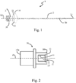
- is a schematic side view of an ultrasonic knife according to an embodiment;
- Fig. 2:
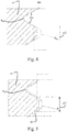
- is a schematic illustration of a sonotrode comprising an internal thread for cooperating with the external thread of the ultrasonic knife;
- Fig. 3:
- is a schematic perspective illustration of the ultrasonic knife;
- Fig. 4:
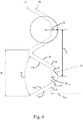
- is an enlarged illustration of an UNJ standard external thread cooperating with an UNJ standard internal thread;
- Fig. 5:
- is an enlarged illustration of the external thread of the ultrasonic knife according to an embodiment in cooperation with an UNJ standard internal thread of a sonotrode;
- Fig. 6:
- is a further enlarged illustration of the external thread of the ultrasonic knife in cooperation with the internal thread of the sonotrode;
- Fig. 7:
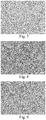
- is an SEM image of a cemented carbide material used for the ultrasonic knife in an Example 1;
- Fig. 8:
- is an SEM image of a cemented carbide material used for the ultrasonic knife in an Example 2; and
- Fig. 9:
- is an SEM image of a cemented carbide material used for the ultrasonic knife in an Example 3.
- An embodiment of the invention will now be described with reference to the drawings.
- As can be seen in
Fig. 1 andFig. 3 , theultrasonic knife 1 according to the embodiment has a cuttingportion 2 adapted to cut material to be cut on a first end and afastening portion 3 for connecting theultrasonic knife 1 to asonotrode 10 on the other end. The cuttingportion 2 has an elongated shape and tapers towards a cuttingtip 21 formed at the first end of theultrasonic knife 1, the first end facing away from thefastening portion 3. Cuttingedges 20 are formed along the sides of the cuttingportion 2. Although a specific shape of the cuttingportion 2 is shown inFig. 1 andFig. 3 , it should be noted that other shapes are also possible. - At the end facing away from the cutting
portion 2, thefastening portion 3 of theultrasonic knife 1 is provided with anexternal thread 30 the features of which will be described more in detail below. A substantially ring-shapedprotrusion 31 which laterally projects further than theexternal thread 30 is formed between the cuttingportion 2 and theexternal thread 30. Theprotrusion 31 has an annularaxial abutment surface 32 which extends substantially perpendicular to a longitudinal axis L of theultrasonic knife 1 and which is adapted to abut against a corresponding annularaxial abutment surface 12 of thesonotrode 10. - A substantially cylindrical
radial abutment surface 33 adjoins the annularaxial abutment surface 32 in the direction towards theexternal thread 30. A substantiallycylindrical clearance surface 34, having a smaller diameter than theradial abutment surface 33 and than theexternal thread 30, is formed between theradial abutment surface 33 and theexternal thread 30. - The whole
ultrasonic knife 1, i.e. the cuttingportion 2 and thefastening portion 3 having theexternal thread 30 are monolithically formed in one piece from cemented carbide material. The cemented carbide material comprises hard particles which are at least predominantly formed by tungsten carbide (WC) the space between which is filled by a ductile metallic binder. The specific composition of the cemented carbide material will be described further below. The specific shape of the cuttingportion 2 is formed by grinding in order to achieve sharp cutting edges 20. - A
typical sonotrode 10 will briefly be explained with reference toFig. 2 . Thesonotrode 10 typically has a substantially cylinder symmetrical shape with a main axis Z. Afirst end 10a of thesonotrode 10 is adapted for connection to an interface of an ultrasound device (not shown). Thesecond end 10b of thesonotrode 10 is provided with acentral bore 11 adapted for receiving thefastening portion 3 of theultrasonic knife 1. Thecentral bore 11 is provided with aninternal thread 15 which is a standard internal thread such as a metric standard ISO internal thread or a standard UTS internal thread. In the following, the features of the embodiment will be described with reference to aninternal thread 15 being a UNJ standard internal thread. - The
second end 10b of thesonotrode 10 has a substantially annularaxial abutment surface 12 for supporting the annularaxial abutment surface 32 of theultrasonic knife 1. A substantially cylindricalradial abutment surface 13 is formed in thecentral bore 10 between theaxial abutment surface 12 and theinternal thread 15. Theradial abutment surface 13 has a diameter which corresponds to the diameter of the cylindricalradial abutment surface 33 of theultrasonic knife 1. When theultrasonic knife 1 is connected to thesonotrode 10, theexternal thread 30 of theultrasonic knife 1 is screwed into theinternal thread 15 of thesonotrode 10 until theaxial abutment surface 32 of theultrasonic knife 1 abuts against the correspondingaxial abutment surface 12 of thesonotrode 10. Theultrasonic knife 1 is centered in the radial direction (with regard to the longitudinal axis L) by interaction of theradial abutment surface 33 of theultrasonic knife 1 with theradial abutment surface 13 of thesonotrode 10. - Next the shape of the
external thread 30 of thefastening portion 3 will be described more in detail. First, cooperation of a UNJ standardexternal thread 30a with a UNJ standard internal thread will be described with reference toFig. 4 . Then, the difference of theexternal thread 30 according to the embodiment as compared to a standard external thread will be explained with reference toFig. 5 andFig. 6 . - As can be seen in
Fig. 4 , each thread turn of a standardinternal thread 15 has a well-defined shape with a standard angle α formed betweenadjacent thread flanks 15a and with given root radius RSI of theinternal thread 15. Similarly, the thread turns of a standardexternal thread 30a are also well-defined with regard to the angle between adjacent thread flanks and the root radius RSE of theexternal thread 30a. Further, the pitch p of the thread is clearly defined for standard threads (the half of the pitch p/2 being shown inFig. 4 ). - Turning now to
Fig. 5 which illustrates anexternal thread 30 according to the embodiment in cooperation with the standardinternal thread 15, it can be seen that theroot 35 of theexternal thread 30 according to the embodiment has an increased root radius R as compared to the standardexternal thread 30a. The increased root radius R can best be expressed as a function of the pitch p of the thread connection. According to the embodiment, theexternal thread 30 of theultrasonic knife 1 has a root radius R within the range of 0.2*p ≤ R ≤ 0.3*p. In this way, theexternal thread 30 formed in the cemented carbide material of theultrasonic knife 1 is made substantially more robust as compared to an external thread according to the standard. Preferably, the root radius can be in the range of 0.24*p ≤ R ≤ 0.285*p. In has been found that the robustness of theexternal thread 30 formed in the cemented carbide material of theultrasonic knife 1 can be substantially increased by selecting the root radius R as a function of the thread pitch p in this range. It has been found that this range works particularly well in the range of nominal thread diameters from approximately 3 mm to approximately 13 mm. - With reference to
Fig. 6 , it can be seen that the transitions T between theroot 35 and the thread flanks 34, i.e. the transitions where the thread flanks 34 extend tangential to theroot 35, define a maximum root diameter dmax of theexternal thread 30. Further, the thread crests 15b of theinternal thread 15 define a minimum diameter Dmin. Theexternal thread 30 according to the embodiment is adapted such that the maximum root diameter dmax is smaller or equal to the minimum diameter Dmin of theinternal thread 15 in thesonotrode 10. Thesonotrode 10 and theultrasonic knife 1 together form an ultrasonic cutting system. Although the features of theinternal thread 15 and the specifically adapted cooperatingexternal thread 30 were described above with reference to a UNJ standard thread, the same holds for metric standard ISO threads. - The
ultrasonic knife 1 according to the embodiment is made from a cemented carbide material comprising: 5.5-13 wt.-% Co, a Cr content with a relation of Cr/Co in wt.-% of 0.04 ≤ Cr/Co ≤ 0.06, a Mo content with a relation of Mo/Co in wt.-% of 0.02 ≤ Mo/Co ≤ 0.04, a content of V and Cr in relation to Co in wt.-% of 0.04 ≤ (V + Cr)/Co ≤ 0.07, unavoidable impurities of in total ≤ 0.15 wt.-%, and the remainder WC. The WC grains in the cemented carbide material have an average grain size in the range from 0.5 µm to 1.2 µm. Preferably, the cemented carbide material can have a Co content within the range from 6.5-11 wt.-% Co. The unavoidable impurities can in particular comprise TiC, TaC and/or NbC. - The cemented carbide material according to the invention was produced by powder metallurgy methods using WC powder having a particle size (Fisher sieve sizes; FSSS) of 0.6 µm, Co powder having an FSSS particle size of 0.8 µm, Cr3C2 powder having an FSSS particle size of 1.5 µm, Cr2N powder having an FSSS particle size of 1.5 µm, Mo2C powder having an FSSS particle size of 1.5 µm; and VC powder having an FSSS particle size of 1 µm, by mixing the respective powders in a solvent in a ball-mill/attritor and subsequent spray-drying in a conventional manner. The resulting granulate was compacted and shaped into a green body of the desired shape and was subsequently sintered in a conventional manner in order to obtain a sintered cemented carbide body.
Ultrasonic knifes 1 were manufactured from the sintered cemented carbide bodies by grinding. - The
fastening portion 3 of theultrasonic knife 1 and in particular theexternal thread 30 was subjected to blasting treatment with a particle beam of alumina grid. The pressure of the particle beam was adjusted such that a compressive stress level was formed in a surface region of the cemented carbide material in thefastening portion 3 with a pressure gradient towards the interior of thefastening portion 3. - The average grain size of the tungsten carbide grains in the cemented carbide material was determined according to the "equivalent circle diameter (ECD" method from EBSD (electron backscatter diffraction) images. This method is e.g. described in "Development of a quantitative method for grain size measurement using EBSD", Master of Science Thesis, Stockholm 2012, by Fredrik Josefsson.
-
Ultrasonic knives 1 made from different cemented carbide compositions were manufactured and tested against an ultrasonic knife according to a comparative example. - An ultrasonic knife according to Example 1 was produced in one piece from a cemented carbide material of 6 wt.-% Co, 0.29 wt.-% Cr (corresponding to 0.35 wt.-% Cr3C2), 0.19 wt.-% Mo (corresponding to 0.2 wt.-% Mo2C), 0.08 wt.-% V (corresponding to 0.1 wt.-% VC), remainder WC and unavoidable impurities (of less than 0.1 wt.-%) according to the above described production routine. Thus, the Cr/Co ratio was 0.048, the Mo/Co ratio was 0.032 and the (V + Cr)/Co ratio was 0.062. The average grain size of the WC grains was determined to be approx. 0.75 µm. An SEM image of the cemented carbide material is shown in
Fig. 7 . Anexternal thread 30 was formed on thefastening portion 3 by grinding. Theexternal thread 30 was based on a metric standard ISO external thread M10 with increased root radius R of R = 0.26*p, i.e. (given the pitch p of 1.5 mm for M10) a root radius R of 0,39 mm. - An ultrasonic knife was produced as a comparative example in one piece from a cemented carbide material consisting of 10 wt.-% Co, 0.42 wt.-% Cr (corresponding to 0.5 wt.-% Cr3C2), 0.16 wt.-% V (corresponding to 0.2 wt.-% VC), remainder WC and unavoidable impurities according to the above described production routine. The average grain size of the WC grains was approx. 0.7 µm. A metric standard ISO external thread M10 was formed on the
fastening portion 3 by grinding. - An ultrasonic knife according to Example 2 was produced in one piece from a cemented carbide material of 7.5 wt.-% Co, 0.38 wt.-% Cr (corresponding to 0.45 wt.-% Cr3C2), 0.24 wt.-% Mo (corresponding to 0.25 wt.-% Mo2C), 0.08 wt.-% V (corresponding to 0.1 wt.-% VC), remainder WC and unavoidable impurities (of less than 0.1 wt.-%) according to the above described production routine. Thus, the Cr/Co ratio was 0.051, the Mo/Co ratio was 0.032 and the (V + Cr)/Co ratio was 0.061. The average grain size of the WC grains was determined to be approx. 0.74 µm. An SEM image of the cemented carbide material is shown in
Fig.8 . Anexternal thread 30 was formed on thefastening portion 3 by grinding. Theexternal thread 30 was based on a metric standard ISO external thread M10 with increased root radius R of R = 0.24*p, i.e. (given the pitch p of 1.5 mm for M10) a root radius R of 0,36 mm. - An ultrasonic knife according to Example 3 was produced in one piece from a cemented carbide material of 10 wt.-% Co, 0.46 wt.-% Cr (corresponding to 0.55 wt.-% Cr3C2), 0.28 wt.-% Mo (corresponding to 0.3 wt.-% Mo2C), 0.12 wt.-% V (corresponding to 0.15 wt.-% VC), remainder WC and unavoidable impurities (of less than 0.15 wt.-%) according to the above described production routine. Thus, the Cr/Co ratio was 0.046, the Mo/Cr ratio was 0.028 and the (V + Cr)/Co ratio was 0.058. The average grain size of the WC grains was determined to be approx. 0.74 µm. An SEM image of the cemented carbide material is shown in
Fig.8 . Anexternal thread 30 was formed on thefastening portion 3 by grinding. Theexternal thread 30 was based on a metric standard ISO external thread M10 with increased root radius R of R = 0.24*p, i.e. (given the pitch p of 1.5 mm for M10) a root radius R of 0,36 mm. - An ultrasonic knife according to Example 4 was produced in one piece from a cemented carbide material of 12 wt.-% Co, 0.58 wt.-% Cr (corresponding to 0.67 wt.-% Cr3C2), 0.31 wt.-% Mo (corresponding to 0.33 wt.-% Mo2C), 0.10 wt.-% V (corresponding to 0.12 wt.-% VC), remainder WC and unavoidable impurities (of less than 0.15 wt.-%) according to the above described production routine. Thus, the Cr/Co ratio was 0.048, the Mo/Cr ratio was 0.026 and the (V + Cr)/Co ratio was 0.057. The average grain size of the WC grains was determined to be approx. 0.81 µm. An
external thread 30 was formed on thefastening portion 3 by grinding. Theexternal thread 30 was based on a metric standard ISO external thread M10 with increased root radius R of R = 0.26*p, i.e. (given the pitch p of 1.5 mm for M10) a root radius R of 0,39 mm. - Ultrasonic knives according to the Comparative Example and to Examples 1 to 4 were mounted to sonotrodes 10 having a metric standard ISO external thread M10. The ultrasonic knives were then tested under harsh cutting conditions cutting honeycomb structure material for the aerospace industry. The cutting speed was continuously increased until breakage of the ultrasonic knife occurred.
- The ultrasonic knives according to Examples 1 to 4 all achieved a substantially increased lifetime as compared to the Comparative Example. Further, the ultrasonic knives according to Examples 1 to 3 resulted in an even better surface quality of the cut material as compared to Example 4, which is believed to be due to the enhanced stiffness of the ultrasonic knives according to Examples 1 to 3.
Claims (9)
- An ultrasonic knife (1)having a cutting portion (2) comprising at least one cutting edge (20) and a fastening portion (3) comprising an external thread (30) for connection to a sonotrode (10),characterized in that the cutting portion (2) and the fastening portion (3) are formed in one piece from cemented carbide material,wherein the cemented carbide material comprises hard particles at least predominantly formed by tungsten carbide, and a metallic binder,wherein the external thread (30) of the fastening section (3) has a thread pitch p and is shaped such that the root (35) of the thread turns has a rounded shape with a root radius R of 0.2*p ≤ R ≤ 0.3*p.
- An ultrasonic knife (1)having a cutting portion (2) comprising at least one cutting edge (20) and a fastening portion (3) comprising an external thread (30) for connection to a sonotrode (10),characterized in that the cutting portion (2) and the fastening portion (3) are formed in one piece from cemented carbide material,wherein the cemented carbide material comprises hard particles at least predominantly formed by tungsten carbide, and a metallic binder,wherein the cemented carbide material comprises:5.5-13 wt.-% Co, preferably 6.5-11 wt.-% Co,a Cr content with a relation of Cr/Co in wt.-% of 0.04 ≤ Cr/Co ≤ 0.06,a Mo content with a relation of Mo/Co in wt.-% of 0.02 ≤ Mo/Co ≤ 0.04,a content of V and Cr in relation to Co in wt.-% of 0.04 ≤ (V + Cr)/Co ≤ 0.07,unavoidable impurities of in total ≤ 0.15 wt.-%, andremainder WC.
- The ultrasonic knife according to claim 2, wherein the external thread (30) of the fastening section (3) has a thread pitch p and is shaped such that the root (35) of the thread turns has a rounded shape with a root radius R of 0.2*p ≤ R ≤ 0.3*p.
- The ultrasonic knife according to claim 1 or claim 3, wherein the root radius R is in the range 0.24*p ≤ R ≤ 0.285*p.
- The ultrasonic knife according to any one of the preceding claims, wherein the external thread (30) has a nominal thread diameter in the range from 3 mm to 13 mm, preferably from 5 mm to 10 mm.
- The ultrasonic knife according to any one of the preceding claims, wherein the WC grains in the cemented carbide material have an average grain size in the range from 0.5-1.2 µm, the average grain size being determined according to the "equivalent circle diameter, ECD" method from EBSD, electron backscatter diffraction, images.
- The ultrasonic knife according to any one of claims 1 to 6, wherein the external thread (30) is adapted to threadingly cooperate with a metric standard ISO internal thread in a sonotrode (10).
- The ultrasonic knife according to any one of claims 1 to 6, wherein the external thread is adapted to threadingly cooperate with a standard UTS internal thread in a sonotrode (10).
- An ultrasonic cutting system comprisinga sonotrode (10) for generating ultrasonic oscillations having an internal thread (15) andan ultrasonic knife (1) according to any one of claims 1 to 8,wherein the external thread (30) of the ultrasonic knife (1) is threadingly engaged with the internal thread (15) of the sonotrode (10),the internal thread (15) of the sonotrode having a minimum diameter Dmin defined by the thread crests (15b) of the internal thread (15),the external thread (30) of the ultrasonic knife (1) having a maximum root diameter dmax defined by the transition (T) from the root radius R to the thread flanks (34),wherein dmax ≤ Dmin.
Priority Applications (5)
| Application Number | Priority Date | Filing Date | Title |
|---|---|---|---|
| EP18212995.7A EP3670039B1 (en) | 2018-12-17 | 2018-12-17 | Ultrasonic knife and ultrasonic cutting system |
| ES18212995T ES2898442T3 (en) | 2018-12-17 | 2018-12-17 | Ultrasonic blade and ultrasonic cutting system |
| US17/415,114 US11890769B2 (en) | 2018-12-17 | 2019-11-27 | Ultrasonic knife and ultrasonic cutting system |
| CA3122885A CA3122885C (en) | 2018-12-17 | 2019-11-27 | Ultrasonic knife and ultrasonic cutting system |
| PCT/EP2019/082701 WO2020126364A1 (en) | 2018-12-17 | 2019-11-27 | Ultrasonic knife and ultrasonic cutting system |
Applications Claiming Priority (1)
| Application Number | Priority Date | Filing Date | Title |
|---|---|---|---|
| EP18212995.7A EP3670039B1 (en) | 2018-12-17 | 2018-12-17 | Ultrasonic knife and ultrasonic cutting system |
Publications (2)
| Publication Number | Publication Date |
|---|---|
| EP3670039A1 EP3670039A1 (en) | 2020-06-24 |
| EP3670039B1 true EP3670039B1 (en) | 2021-09-29 |
Family
ID=64744407
Family Applications (1)
| Application Number | Title | Priority Date | Filing Date |
|---|---|---|---|
| EP18212995.7A Active EP3670039B1 (en) | 2018-12-17 | 2018-12-17 | Ultrasonic knife and ultrasonic cutting system |
Country Status (5)
| Country | Link |
|---|---|
| US (1) | US11890769B2 (en) |
| EP (1) | EP3670039B1 (en) |
| CA (1) | CA3122885C (en) |
| ES (1) | ES2898442T3 (en) |
| WO (1) | WO2020126364A1 (en) |
Family Cites Families (8)
| Publication number | Priority date | Publication date | Assignee | Title |
|---|---|---|---|---|
| US4567797A (en) * | 1984-01-30 | 1986-02-04 | Folk Donald C | Ultrasonic cutting apparatus and methods |
| US5695510A (en) * | 1992-02-20 | 1997-12-09 | Hood; Larry L. | Ultrasonic knife |
| JP3706239B2 (en) * | 1998-02-18 | 2005-10-12 | 日本特殊陶業株式会社 | Ultrasonic horn |
| JP4559320B2 (en) * | 2005-08-08 | 2010-10-06 | リンテック株式会社 | Sheet cutting device |
| JP4890868B2 (en) * | 2006-01-18 | 2012-03-07 | リンテック株式会社 | Sheet cutting device and cutting method |
| US9387005B2 (en) * | 2013-06-28 | 2016-07-12 | Misonix, Incorporated | Ultrasonic cutting blade with cooling liquid conduction |
| WO2015133006A1 (en) * | 2014-03-03 | 2015-09-11 | オリンパス株式会社 | Ultrasound instrument and probe |
| CN207387730U (en) * | 2017-10-16 | 2018-05-22 | 郑州市钻石精密制造有限公司 | A kind of thread handle ultrasound straight knife |
-
2018
- 2018-12-17 EP EP18212995.7A patent/EP3670039B1/en active Active
- 2018-12-17 ES ES18212995T patent/ES2898442T3/en active Active
-
2019
- 2019-11-27 US US17/415,114 patent/US11890769B2/en active Active
- 2019-11-27 CA CA3122885A patent/CA3122885C/en active Active
- 2019-11-27 WO PCT/EP2019/082701 patent/WO2020126364A1/en active Application Filing
Also Published As
| Publication number | Publication date |
|---|---|
| CA3122885A1 (en) | 2020-06-25 |
| WO2020126364A1 (en) | 2020-06-25 |
| ES2898442T3 (en) | 2022-03-07 |
| EP3670039A1 (en) | 2020-06-24 |
| US11890769B2 (en) | 2024-02-06 |
| US20220048214A1 (en) | 2022-02-17 |
| CA3122885C (en) | 2023-05-23 |
Similar Documents
| Publication | Publication Date | Title |
|---|---|---|
| RU2503522C2 (en) | Composite inserts with polycrystalline diamonds | |
| JP4662599B2 (en) | Manufacturing method of submicron cemented carbide with increased toughness | |
| JP2010514933A (en) | Corrosion resistant tool for cold forming | |
| JP6439975B2 (en) | Cermet manufacturing method | |
| JP2006316309A (en) | High wear resistant tough steel having excellent fatigue strength | |
| JP2009035810A (en) | Cemented carbide | |
| WO2016203674A1 (en) | Cemented carbide and cutting tool | |
| CN110923535A (en) | Hard alloy and preparation method and application thereof | |
| JP2006328539A (en) | Coated cemented carbide, and tool | |
| EP2107045A1 (en) | Diamond sinter and process for producing the same | |
| EP3670039B1 (en) | Ultrasonic knife and ultrasonic cutting system | |
| JP4297987B2 (en) | High-strength fine-grain diamond sintered body and tool using the same | |
| JP2597046B2 (en) | Cutting insert and its manufacturing method | |
| JP2004076049A (en) | Hard metal of ultra-fine particles | |
| JP6123138B2 (en) | Cemented carbide, microdrill, and method of manufacturing cemented carbide | |
| JP2007162067A (en) | Fine-grained cemented carbide for fine tool and production method | |
| WO2019244429A1 (en) | Diamond joined body, and method for manufacturing diamond joined body | |
| JP7173426B1 (en) | Cemented carbide and cutting tools | |
| JP2007126326A (en) | Diamond sintered body | |
| JP2016041853A (en) | Cemented carbide, micro-drill and method for producing cemented carbide | |
| JPH1161317A (en) | Ball end mill made of cemented carbide, having ball nose end half excellent in wear resistance | |
| JP2001181777A (en) | Cylinder core and anvil core for superhigh pressure generating device | |
| JP2017531736A (en) | Layer manufacturing method | |
| EP3971137B1 (en) | Tungsten carbide powder | |
| KR100818572B1 (en) | High-strength and highly-wear-resistant sintered diamond object and manufacturing method of the same |
Legal Events
| Date | Code | Title | Description |
|---|---|---|---|
| PUAI | Public reference made under article 153(3) epc to a published international application that has entered the european phase |
Free format text: ORIGINAL CODE: 0009012 |
|
| STAA | Information on the status of an ep patent application or granted ep patent |
Free format text: STATUS: THE APPLICATION HAS BEEN PUBLISHED |
|
| AK | Designated contracting states |
Kind code of ref document: A1 Designated state(s): AL AT BE BG CH CY CZ DE DK EE ES FI FR GB GR HR HU IE IS IT LI LT LU LV MC MK MT NL NO PL PT RO RS SE SI SK SM TR |
|
| AX | Request for extension of the european patent |
Extension state: BA ME |
|
| STAA | Information on the status of an ep patent application or granted ep patent |
Free format text: STATUS: REQUEST FOR EXAMINATION WAS MADE |
|
| 17P | Request for examination filed |
Effective date: 20201130 |
|
| RBV | Designated contracting states (corrected) |
Designated state(s): AL AT BE BG CH CY CZ DE DK EE ES FI FR GB GR HR HU IE IS IT LI LT LU LV MC MK MT NL NO PL PT RO RS SE SI SK SM TR |
|
| REG | Reference to a national code |
Ref country code: DE Ref legal event code: R079 Ref document number: 602018024219 Country of ref document: DE Free format text: PREVIOUS MAIN CLASS: B22F0005000000 Ipc: B26D0001000000 |
|
| GRAP | Despatch of communication of intention to grant a patent |
Free format text: ORIGINAL CODE: EPIDOSNIGR1 |
|
| STAA | Information on the status of an ep patent application or granted ep patent |
Free format text: STATUS: GRANT OF PATENT IS INTENDED |
|
| RIC1 | Information provided on ipc code assigned before grant |
Ipc: F16B 33/04 20060101ALN20210603BHEP Ipc: C22C 29/08 20060101ALI20210603BHEP Ipc: C22C 29/06 20060101ALI20210603BHEP Ipc: B22F 5/06 20060101ALI20210603BHEP Ipc: B22F 5/00 20060101ALI20210603BHEP Ipc: B26D 7/26 20060101ALI20210603BHEP Ipc: B26D 7/08 20060101ALI20210603BHEP Ipc: B26D 1/00 20060101AFI20210603BHEP |
|
| INTG | Intention to grant announced |
Effective date: 20210622 |
|
| RAP3 | Party data changed (applicant data changed or rights of an application transferred) |
Owner name: CERATIZIT COMO S.P.A. |
|
| GRAS | Grant fee paid |
Free format text: ORIGINAL CODE: EPIDOSNIGR3 |
|
| GRAA | (expected) grant |
Free format text: ORIGINAL CODE: 0009210 |
|
| STAA | Information on the status of an ep patent application or granted ep patent |
Free format text: STATUS: THE PATENT HAS BEEN GRANTED |
|
| AK | Designated contracting states |
Kind code of ref document: B1 Designated state(s): AL AT BE BG CH CY CZ DE DK EE ES FI FR GB GR HR HU IE IS IT LI LT LU LV MC MK MT NL NO PL PT RO RS SE SI SK SM TR |
|
| REG | Reference to a national code |
Ref country code: GB Ref legal event code: FG4D |
|
| REG | Reference to a national code |
Ref country code: CH Ref legal event code: EP Ref country code: AT Ref legal event code: REF Ref document number: 1433806 Country of ref document: AT Kind code of ref document: T Effective date: 20211015 |
|
| REG | Reference to a national code |
Ref country code: DE Ref legal event code: R096 Ref document number: 602018024219 Country of ref document: DE |
|
| REG | Reference to a national code |
Ref country code: IE Ref legal event code: FG4D |
|
| REG | Reference to a national code |
Ref country code: LT Ref legal event code: MG9D |
|
| PG25 | Lapsed in a contracting state [announced via postgrant information from national office to epo] |
Ref country code: FI Free format text: LAPSE BECAUSE OF FAILURE TO SUBMIT A TRANSLATION OF THE DESCRIPTION OR TO PAY THE FEE WITHIN THE PRESCRIBED TIME-LIMIT Effective date: 20210929 Ref country code: HR Free format text: LAPSE BECAUSE OF FAILURE TO SUBMIT A TRANSLATION OF THE DESCRIPTION OR TO PAY THE FEE WITHIN THE PRESCRIBED TIME-LIMIT Effective date: 20210929 Ref country code: SE Free format text: LAPSE BECAUSE OF FAILURE TO SUBMIT A TRANSLATION OF THE DESCRIPTION OR TO PAY THE FEE WITHIN THE PRESCRIBED TIME-LIMIT Effective date: 20210929 Ref country code: RS Free format text: LAPSE BECAUSE OF FAILURE TO SUBMIT A TRANSLATION OF THE DESCRIPTION OR TO PAY THE FEE WITHIN THE PRESCRIBED TIME-LIMIT Effective date: 20210929 Ref country code: LT Free format text: LAPSE BECAUSE OF FAILURE TO SUBMIT A TRANSLATION OF THE DESCRIPTION OR TO PAY THE FEE WITHIN THE PRESCRIBED TIME-LIMIT Effective date: 20210929 Ref country code: BG Free format text: LAPSE BECAUSE OF FAILURE TO SUBMIT A TRANSLATION OF THE DESCRIPTION OR TO PAY THE FEE WITHIN THE PRESCRIBED TIME-LIMIT Effective date: 20211229 Ref country code: NO Free format text: LAPSE BECAUSE OF FAILURE TO SUBMIT A TRANSLATION OF THE DESCRIPTION OR TO PAY THE FEE WITHIN THE PRESCRIBED TIME-LIMIT Effective date: 20211229 |
|
| REG | Reference to a national code |
Ref country code: NL Ref legal event code: MP Effective date: 20210929 |
|
| PG25 | Lapsed in a contracting state [announced via postgrant information from national office to epo] |
Ref country code: LV Free format text: LAPSE BECAUSE OF FAILURE TO SUBMIT A TRANSLATION OF THE DESCRIPTION OR TO PAY THE FEE WITHIN THE PRESCRIBED TIME-LIMIT Effective date: 20210929 Ref country code: GR Free format text: LAPSE BECAUSE OF FAILURE TO SUBMIT A TRANSLATION OF THE DESCRIPTION OR TO PAY THE FEE WITHIN THE PRESCRIBED TIME-LIMIT Effective date: 20211230 |
|
| REG | Reference to a national code |
Ref country code: ES Ref legal event code: FG2A Ref document number: 2898442 Country of ref document: ES Kind code of ref document: T3 Effective date: 20220307 |
|
| PG25 | Lapsed in a contracting state [announced via postgrant information from national office to epo] |
Ref country code: IS Free format text: LAPSE BECAUSE OF FAILURE TO SUBMIT A TRANSLATION OF THE DESCRIPTION OR TO PAY THE FEE WITHIN THE PRESCRIBED TIME-LIMIT Effective date: 20220129 Ref country code: SK Free format text: LAPSE BECAUSE OF FAILURE TO SUBMIT A TRANSLATION OF THE DESCRIPTION OR TO PAY THE FEE WITHIN THE PRESCRIBED TIME-LIMIT Effective date: 20210929 Ref country code: RO Free format text: LAPSE BECAUSE OF FAILURE TO SUBMIT A TRANSLATION OF THE DESCRIPTION OR TO PAY THE FEE WITHIN THE PRESCRIBED TIME-LIMIT Effective date: 20210929 Ref country code: PT Free format text: LAPSE BECAUSE OF FAILURE TO SUBMIT A TRANSLATION OF THE DESCRIPTION OR TO PAY THE FEE WITHIN THE PRESCRIBED TIME-LIMIT Effective date: 20220131 Ref country code: PL Free format text: LAPSE BECAUSE OF FAILURE TO SUBMIT A TRANSLATION OF THE DESCRIPTION OR TO PAY THE FEE WITHIN THE PRESCRIBED TIME-LIMIT Effective date: 20210929 Ref country code: NL Free format text: LAPSE BECAUSE OF FAILURE TO SUBMIT A TRANSLATION OF THE DESCRIPTION OR TO PAY THE FEE WITHIN THE PRESCRIBED TIME-LIMIT Effective date: 20210929 Ref country code: EE Free format text: LAPSE BECAUSE OF FAILURE TO SUBMIT A TRANSLATION OF THE DESCRIPTION OR TO PAY THE FEE WITHIN THE PRESCRIBED TIME-LIMIT Effective date: 20210929 Ref country code: AL Free format text: LAPSE BECAUSE OF FAILURE TO SUBMIT A TRANSLATION OF THE DESCRIPTION OR TO PAY THE FEE WITHIN THE PRESCRIBED TIME-LIMIT Effective date: 20210929 |
|
| REG | Reference to a national code |
Ref country code: DE Ref legal event code: R097 Ref document number: 602018024219 Country of ref document: DE |
|
| PG25 | Lapsed in a contracting state [announced via postgrant information from national office to epo] |
Ref country code: MC Free format text: LAPSE BECAUSE OF FAILURE TO SUBMIT A TRANSLATION OF THE DESCRIPTION OR TO PAY THE FEE WITHIN THE PRESCRIBED TIME-LIMIT Effective date: 20210929 Ref country code: DK Free format text: LAPSE BECAUSE OF FAILURE TO SUBMIT A TRANSLATION OF THE DESCRIPTION OR TO PAY THE FEE WITHIN THE PRESCRIBED TIME-LIMIT Effective date: 20210929 |
|
| PLBE | No opposition filed within time limit |
Free format text: ORIGINAL CODE: 0009261 |
|
| STAA | Information on the status of an ep patent application or granted ep patent |
Free format text: STATUS: NO OPPOSITION FILED WITHIN TIME LIMIT |
|
| 26N | No opposition filed |
Effective date: 20220630 |
|
| REG | Reference to a national code |
Ref country code: BE Ref legal event code: MM Effective date: 20211231 |
|
| PG25 | Lapsed in a contracting state [announced via postgrant information from national office to epo] |
Ref country code: IE Free format text: LAPSE BECAUSE OF NON-PAYMENT OF DUE FEES Effective date: 20211217 |
|
| PG25 | Lapsed in a contracting state [announced via postgrant information from national office to epo] |
Ref country code: SI Free format text: LAPSE BECAUSE OF FAILURE TO SUBMIT A TRANSLATION OF THE DESCRIPTION OR TO PAY THE FEE WITHIN THE PRESCRIBED TIME-LIMIT Effective date: 20210929 Ref country code: BE Free format text: LAPSE BECAUSE OF NON-PAYMENT OF DUE FEES Effective date: 20211231 |
|
| REG | Reference to a national code |
Ref country code: AT Ref legal event code: UEP Ref document number: 1433806 Country of ref document: AT Kind code of ref document: T Effective date: 20210929 |
|
| PG25 | Lapsed in a contracting state [announced via postgrant information from national office to epo] |
Ref country code: CY Free format text: LAPSE BECAUSE OF FAILURE TO SUBMIT A TRANSLATION OF THE DESCRIPTION OR TO PAY THE FEE WITHIN THE PRESCRIBED TIME-LIMIT Effective date: 20210929 |
|
| PG25 | Lapsed in a contracting state [announced via postgrant information from national office to epo] |
Ref country code: SM Free format text: LAPSE BECAUSE OF FAILURE TO SUBMIT A TRANSLATION OF THE DESCRIPTION OR TO PAY THE FEE WITHIN THE PRESCRIBED TIME-LIMIT Effective date: 20210929 Ref country code: HU Free format text: LAPSE BECAUSE OF FAILURE TO SUBMIT A TRANSLATION OF THE DESCRIPTION OR TO PAY THE FEE WITHIN THE PRESCRIBED TIME-LIMIT; INVALID AB INITIO Effective date: 20181217 |
|
| PGFP | Annual fee paid to national office [announced via postgrant information from national office to epo] |
Ref country code: GB Payment date: 20231220 Year of fee payment: 6 |
|
| PGFP | Annual fee paid to national office [announced via postgrant information from national office to epo] |
Ref country code: LU Payment date: 20231220 Year of fee payment: 6 Ref country code: IT Payment date: 20231228 Year of fee payment: 6 Ref country code: FR Payment date: 20231222 Year of fee payment: 6 Ref country code: DE Payment date: 20231214 Year of fee payment: 6 Ref country code: CZ Payment date: 20231211 Year of fee payment: 6 Ref country code: AT Payment date: 20231221 Year of fee payment: 6 |
|
| PGFP | Annual fee paid to national office [announced via postgrant information from national office to epo] |
Ref country code: ES Payment date: 20240130 Year of fee payment: 6 |
|
| PG25 | Lapsed in a contracting state [announced via postgrant information from national office to epo] |
Ref country code: MK Free format text: LAPSE BECAUSE OF FAILURE TO SUBMIT A TRANSLATION OF THE DESCRIPTION OR TO PAY THE FEE WITHIN THE PRESCRIBED TIME-LIMIT Effective date: 20210929 |
|
| PGFP | Annual fee paid to national office [announced via postgrant information from national office to epo] |
Ref country code: CH Payment date: 20240102 Year of fee payment: 6 |
|
| PG25 | Lapsed in a contracting state [announced via postgrant information from national office to epo] |
Ref country code: TR Free format text: LAPSE BECAUSE OF FAILURE TO SUBMIT A TRANSLATION OF THE DESCRIPTION OR TO PAY THE FEE WITHIN THE PRESCRIBED TIME-LIMIT Effective date: 20210929 |
|
| PG25 | Lapsed in a contracting state [announced via postgrant information from national office to epo] |
Ref country code: MT Free format text: LAPSE BECAUSE OF FAILURE TO SUBMIT A TRANSLATION OF THE DESCRIPTION OR TO PAY THE FEE WITHIN THE PRESCRIBED TIME-LIMIT Effective date: 20210929 |