EP3669967B1 - Filter system and replaceable filter cartridge - Google Patents
Filter system and replaceable filter cartridge Download PDFInfo
- Publication number
- EP3669967B1 EP3669967B1 EP19219020.5A EP19219020A EP3669967B1 EP 3669967 B1 EP3669967 B1 EP 3669967B1 EP 19219020 A EP19219020 A EP 19219020A EP 3669967 B1 EP3669967 B1 EP 3669967B1
- Authority
- EP
- European Patent Office
- Prior art keywords
- filter
- end cap
- filter media
- spinner
- oil
- Prior art date
- Legal status (The legal status is an assumption and is not a legal conclusion. Google has not performed a legal analysis and makes no representation as to the accuracy of the status listed.)
- Active
Links
- 239000000463 material Substances 0.000 claims description 35
- 239000012530 fluid Substances 0.000 claims description 15
- 238000004891 communication Methods 0.000 claims description 4
- 239000000126 substance Substances 0.000 claims description 4
- 230000006835 compression Effects 0.000 claims description 3
- 238000007906 compression Methods 0.000 claims description 3
- 230000000295 complement effect Effects 0.000 claims description 2
- 239000000314 lubricant Substances 0.000 claims description 2
- 230000002093 peripheral effect Effects 0.000 claims 2
- 238000000034 method Methods 0.000 description 10
- 239000000853 adhesive Substances 0.000 description 4
- 230000001070 adhesive effect Effects 0.000 description 4
- 238000004581 coalescence Methods 0.000 description 4
- 238000010276 construction Methods 0.000 description 4
- 238000001914 filtration Methods 0.000 description 4
- 230000003647 oxidation Effects 0.000 description 4
- 238000007254 oxidation reaction Methods 0.000 description 4
- 230000008878 coupling Effects 0.000 description 3
- 238000010168 coupling process Methods 0.000 description 3
- 238000005859 coupling reaction Methods 0.000 description 3
- 229920001971 elastomer Polymers 0.000 description 3
- 239000000446 fuel Substances 0.000 description 3
- 239000007800 oxidant agent Substances 0.000 description 3
- 230000001590 oxidative effect Effects 0.000 description 3
- 238000011282 treatment Methods 0.000 description 3
- 239000002699 waste material Substances 0.000 description 3
- 239000004593 Epoxy Substances 0.000 description 2
- 238000004026 adhesive bonding Methods 0.000 description 2
- 238000006243 chemical reaction Methods 0.000 description 2
- 239000007795 chemical reaction product Substances 0.000 description 2
- 238000002485 combustion reaction Methods 0.000 description 2
- 125000003700 epoxy group Chemical group 0.000 description 2
- 239000003822 epoxy resin Substances 0.000 description 2
- 239000000835 fiber Substances 0.000 description 2
- LNEPOXFFQSENCJ-UHFFFAOYSA-N haloperidol Chemical compound C1CC(O)(C=2C=CC(Cl)=CC=2)CCN1CCCC(=O)C1=CC=C(F)C=C1 LNEPOXFFQSENCJ-UHFFFAOYSA-N 0.000 description 2
- 239000004033 plastic Substances 0.000 description 2
- 229920000647 polyepoxide Polymers 0.000 description 2
- UGFAIRIUMAVXCW-UHFFFAOYSA-N Carbon monoxide Chemical compound [O+]#[C-] UGFAIRIUMAVXCW-UHFFFAOYSA-N 0.000 description 1
- 230000004075 alteration Effects 0.000 description 1
- 238000004200 deflagration Methods 0.000 description 1
- 239000000806 elastomer Substances 0.000 description 1
- 238000005516 engineering process Methods 0.000 description 1
- 230000007613 environmental effect Effects 0.000 description 1
- 239000002657 fibrous material Substances 0.000 description 1
- 239000003546 flue gas Substances 0.000 description 1
- 239000007789 gas Substances 0.000 description 1
- 238000003780 insertion Methods 0.000 description 1
- 230000037431 insertion Effects 0.000 description 1
- 238000012986 modification Methods 0.000 description 1
- 230000004048 modification Effects 0.000 description 1
- -1 organic compound isoprenes Chemical class 0.000 description 1
- 229920000620 organic polymer Polymers 0.000 description 1
- 229920001195 polyisoprene Polymers 0.000 description 1
- 229920000642 polymer Polymers 0.000 description 1
- 230000001737 promoting effect Effects 0.000 description 1
- 238000011084 recovery Methods 0.000 description 1
- 238000007789 sealing Methods 0.000 description 1
- 239000002904 solvent Substances 0.000 description 1
- 229920001169 thermoplastic Polymers 0.000 description 1
- 229920001187 thermosetting polymer Polymers 0.000 description 1
- 239000004416 thermosoftening plastic Substances 0.000 description 1
- 238000011144 upstream manufacturing Methods 0.000 description 1
Images


Classifications
-
- B—PERFORMING OPERATIONS; TRANSPORTING
- B01—PHYSICAL OR CHEMICAL PROCESSES OR APPARATUS IN GENERAL
- B01D—SEPARATION
- B01D46/00—Filters or filtering processes specially modified for separating dispersed particles from gases or vapours
- B01D46/0002—Casings; Housings; Frame constructions
- B01D46/0015—Throw-away type filters
-
- B—PERFORMING OPERATIONS; TRANSPORTING
- B01—PHYSICAL OR CHEMICAL PROCESSES OR APPARATUS IN GENERAL
- B01D—SEPARATION
- B01D46/00—Filters or filtering processes specially modified for separating dispersed particles from gases or vapours
- B01D46/0002—Casings; Housings; Frame constructions
- B01D46/0005—Mounting of filtering elements within casings, housings or frames
-
- B—PERFORMING OPERATIONS; TRANSPORTING
- B01—PHYSICAL OR CHEMICAL PROCESSES OR APPARATUS IN GENERAL
- B01D—SEPARATION
- B01D46/00—Filters or filtering processes specially modified for separating dispersed particles from gases or vapours
- B01D46/24—Particle separators, e.g. dust precipitators, using rigid hollow filter bodies
- B01D46/2403—Particle separators, e.g. dust precipitators, using rigid hollow filter bodies characterised by the physical shape or structure of the filtering element
- B01D46/2411—Filter cartridges
- B01D46/2414—End caps including additional functions or special forms
-
- B—PERFORMING OPERATIONS; TRANSPORTING
- B01—PHYSICAL OR CHEMICAL PROCESSES OR APPARATUS IN GENERAL
- B01D—SEPARATION
- B01D46/00—Filters or filtering processes specially modified for separating dispersed particles from gases or vapours
- B01D46/0027—Filters or filtering processes specially modified for separating dispersed particles from gases or vapours with additional separating or treating functions
- B01D46/003—Filters or filtering processes specially modified for separating dispersed particles from gases or vapours with additional separating or treating functions including coalescing means for the separation of liquid
- B01D46/0031—Filters or filtering processes specially modified for separating dispersed particles from gases or vapours with additional separating or treating functions including coalescing means for the separation of liquid with collecting, draining means
-
- B—PERFORMING OPERATIONS; TRANSPORTING
- B01—PHYSICAL OR CHEMICAL PROCESSES OR APPARATUS IN GENERAL
- B01D—SEPARATION
- B01D46/00—Filters or filtering processes specially modified for separating dispersed particles from gases or vapours
- B01D46/0039—Filters or filtering processes specially modified for separating dispersed particles from gases or vapours with flow guiding by feed or discharge devices
- B01D46/0041—Filters or filtering processes specially modified for separating dispersed particles from gases or vapours with flow guiding by feed or discharge devices for feeding
- B01D46/0045—Filters or filtering processes specially modified for separating dispersed particles from gases or vapours with flow guiding by feed or discharge devices for feeding by using vanes
-
- B—PERFORMING OPERATIONS; TRANSPORTING
- B01—PHYSICAL OR CHEMICAL PROCESSES OR APPARATUS IN GENERAL
- B01D—SEPARATION
- B01D46/00—Filters or filtering processes specially modified for separating dispersed particles from gases or vapours
- B01D46/24—Particle separators, e.g. dust precipitators, using rigid hollow filter bodies
- B01D46/26—Particle separators, e.g. dust precipitators, using rigid hollow filter bodies rotatable
-
- B—PERFORMING OPERATIONS; TRANSPORTING
- B01—PHYSICAL OR CHEMICAL PROCESSES OR APPARATUS IN GENERAL
- B01D—SEPARATION
- B01D2271/00—Sealings for filters specially adapted for separating dispersed particles from gases or vapours
- B01D2271/02—Gaskets, sealings
-
- B—PERFORMING OPERATIONS; TRANSPORTING
- B01—PHYSICAL OR CHEMICAL PROCESSES OR APPARATUS IN GENERAL
- B01D—SEPARATION
- B01D2279/00—Filters adapted for separating dispersed particles from gases or vapours specially modified for specific uses
- B01D2279/60—Filters adapted for separating dispersed particles from gases or vapours specially modified for specific uses for the intake of internal combustion engines or turbines
-
- F—MECHANICAL ENGINEERING; LIGHTING; HEATING; WEAPONS; BLASTING
- F01—MACHINES OR ENGINES IN GENERAL; ENGINE PLANTS IN GENERAL; STEAM ENGINES
- F01M—LUBRICATING OF MACHINES OR ENGINES IN GENERAL; LUBRICATING INTERNAL COMBUSTION ENGINES; CRANKCASE VENTILATING
- F01M11/00—Component parts, details or accessories, not provided for in, or of interest apart from, groups F01M1/00 - F01M9/00
- F01M11/03—Mounting or connecting of lubricant purifying means relative to the machine or engine; Details of lubricant purifying means
- F01M2011/031—Mounting or connecting of lubricant purifying means relative to the machine or engine; Details of lubricant purifying means characterised by mounting means
- F01M2011/038—Mounting or connecting of lubricant purifying means relative to the machine or engine; Details of lubricant purifying means characterised by mounting means comprising lubricant-air separators
-
- F—MECHANICAL ENGINEERING; LIGHTING; HEATING; WEAPONS; BLASTING
- F04—POSITIVE - DISPLACEMENT MACHINES FOR LIQUIDS; PUMPS FOR LIQUIDS OR ELASTIC FLUIDS
- F04C—ROTARY-PISTON, OR OSCILLATING-PISTON, POSITIVE-DISPLACEMENT MACHINES FOR LIQUIDS; ROTARY-PISTON, OR OSCILLATING-PISTON, POSITIVE-DISPLACEMENT PUMPS
- F04C29/00—Component parts, details or accessories of pumps or pumping installations, not provided for in groups F04C18/00 - F04C28/00
- F04C29/02—Lubrication; Lubricant separation
- F04C29/026—Lubricant separation
-
- F—MECHANICAL ENGINEERING; LIGHTING; HEATING; WEAPONS; BLASTING
- F04—POSITIVE - DISPLACEMENT MACHINES FOR LIQUIDS; PUMPS FOR LIQUIDS OR ELASTIC FLUIDS
- F04D—NON-POSITIVE-DISPLACEMENT PUMPS
- F04D29/00—Details, component parts, or accessories
- F04D29/70—Suction grids; Strainers; Dust separation; Cleaning
- F04D29/701—Suction grids; Strainers; Dust separation; Cleaning especially adapted for elastic fluid pumps
Definitions
- the present invention generally relates to filters used for a mixed flow of compressible fluid and oil, and more particularly, but not exclusively, to compressor systems having a replaceable coalescence filter cartridge.
- Prior art document US2012167534 relates a filter having a drainage outlet which can be tightly connected to a connecting head.
- Prior art document US2005092179A1 relates generally to a filter arrangement and filtering method for use with a vessel containing a pressurized fluid.
- a compressor system 50 which includes a compressor 52 capable of providing compression to a compressible fluid 54 such as, but not limited to, air.
- a compressible fluid 54 such as, but not limited to, air.
- the compressor 52 can take any variety of forms including but not limited to contact cooled screw compressors. Such contact cooled screw compressors can use any type of lubricant such as but not limited to oil.
- the compressor system 50 can further include one or more devices 56, 58 to remove unwanted content from the flow of compressed air 60 provided by the compressor 52.
- the compressor 52 can be in fluid communication one or more filter(s), air dryer(s), etc such as but not limited to the devices 56 and/or 58 depicted in FIG. 1 .
- the compressor 52 can be coupled with a primary oil filter 56 and a secondary oil filter 58.
- a primary oil filter 56 can be of a centrifugal separator type to remove unwanted oil from the mixed flow of compressed air and oil 60
- the secondary oil filter 56 can be a device that uses a coalescence filter to further remove oil from the flow 62 to produce a cleaner flow 64.
- the coalescence filter 58 might be the only filter used in a compressor system 50, but can still be coupled with further devices for removing unwanted material from the flow of compressed air 60.
- FIGS. 2 and 3 one example of a filter 58 is depicted which takes the form of a coalescence filter system. It will be appreciated that although the example depicted in FIG. 2 is illustrated using reference numeral 58, some systems may not include the device 56, or may include a device 56 but not of the filtering type. No limitation is hereby intended that the filter 58 must be a secondary filter in any type of system that includes the features of the filter.
- Filter system 58 includes a replaceable filter cartridge 66 having a filter media 68 disposed between a spinner 70 and end cap 72. In accordance with the present invention, the replaceable cartridge 66 is inserted around a mesh filter member 74 which is situated upon a mesh holder 76.
- a housing 78 is used to enclose the filter cartridge 66 and form various flow passages for the conveyance of a mixed flow of compressed fluid and oil as well as a filtered flow.
- the housing 78 can be attached to the base of the unit through a threaded or bayonet type connection, but other connection types are also contemplated. In one form the housing 78 is attached using a quarter-turn.
- a mixed flow of compressed air 62 enters the filter system 58 it travels down a conduit and it turned to flow upward and between the mesh holder 76 and the housing 78.
- air is routed between the mesh holder 76 and the housing 78 is passes through the spinner 70 which imparts a circumferential rotation to the flow 62.
- Suitable space is provided between the filter media 68 and the housing 78 to permit swirling passage of the flow 62 and adequate distribution of the flow 62.
- a circular shaped filter media 68 and inner surface of the housing 78 aid in the swirling motion of air.
- a standpipe 80 can be provided to extend away from the mesh holder 76 and is used to receive the flow of compressed fluid 64 after some or all of oil in the mixed flow 62 has been extracted via the filter media 68 and mesh filter element 74.
- the standpipe 80 can be an integral portion of the mesh holder 76, or can be a separate part that is integrated with the mesh holder 76. The flow received into the standpipe 80 is then directed out of the filter system 58 through a passage.
- the filter cartridge 66 can be made as a replaceable module that can be manipulated/handled as a unitary whole as it is inserted into a filter system 58. It is envisioned that such a modular, stand-alone component can include the filter media 68 and at least one of the spinner 70 and end cap 72. In some forms the stand-alone cartridge 66 can include additional components beyond the filter media and either or both of the spinner 70 and end cap 72.
- the filter media 68 can take on a variety of forms suitable to coalesce oil from the mixed stream 62 of compressed fluid and oil.
- the filter media 68 can be made of paper made using any variety of fiber material.
- the filter media 68 can be made of rolled paper, but other forms are also contemplated such as pleated, etc.
- the spinner 70 includes an inner ring 82, outer ring 84, and airflow members 86 extending between the inner and outer rings.
- the airflow members 86 can take on any variety of forms including vanes, orifices, etc. In the form of vanes the airflow members 86 can extend between respective leading and trailing edges in any variety of manners. For example, the airflow members 86 can extend in a straight line between its leading and trailing edges. In some forms a camber line between the leading and trailing edges can be curved. In certain forms the camber line can be continuous or non-continuous. In still other forms the airflow members 86 can extend in a segmented manner between leading and trailing edges. In short, any variety of shapes are contemplated for the airflow members 86 of the spinner.
- the airflow members 86 can furthermore impart any degree of circumferential motion of fluid flowing therethrough. In some forms the airflow members 86 can impart a relatively higher degree of circumferential motion than axial motion of the fluid, while in other forms the airflow members 86 can impart a relatively higher degree of axial motion than circumferential motion. In still other forms the circumferential and axial components of fluid velocity can be the same.
- one or more airflow passages 88 will be formed in the spinner to traverse from an upstream side of the spinner to a downstream side, As such, the shape of the passages (which can be formed by neighboring vanes, for example) can dictate the degree of circumferential motion relative to the degree of axial motion of the air exiting the downstream side of the spinner 70.
- the spinner 70 in the illustrated example includes both inner ring 82 and outer ring 86
- the spinner 70 can include fewer components.
- the spinner 70 can have the outer ring 84 and airflow members 86, but lack the inner ring 82. In such a form the airflow members 86 can be individually affixed to the filter media.
- the spinner 70 can have the inner ring 82 and airflow members 86 but otherwise lack an outer ring 84.
- the spinner 70 can be attached to the filter media 68 via any suitable manner, whether mechanical, bonding, or otherwise. In some forms the spinner 70 can be attached using chemical bonding such as through an adhesive process such as gluing or epoxying. Epoxy can include can be any of a basic component or cured end products of epoxy resins, as well as represent the epoxide functional group. Any suitable type of adhesive is contemplated.
- the end cap 72 can be used to enclose the open interior of the filter media 68.
- the end cap can include an annular slot defined between an inside wall 88 and outside wall 90 which can be used to receive the filter media 68 and in some examples also receive the mesh filter element 74.
- Either or both of the inside wall 88 and outside wall 90 can extend uninterrupted around the periphery of the filter media 68, but in some forms either or both of the inside wall 88 and outside wall 90 can include a broken configuration.
- the size of the annular slot between the inside wall 88 and outside wall 90 can receive both of the filter media 68 and mesh filter element 74.
- the inside wall 88 can include a chamfer or sloped edge to pilot the mesh filter element 74 when the filter cartridge 66 is inserted onto the mesh filter element 74.
- the housing 78 can include a protuberance 92 which can be used to urge the filter cartridge 66 into a seated position upon the mesh holder 76.
- the protuberance 92 can be located on the end cap 72 as depicted in FIG. 6 .
- the protuberance 92 can take on any suitable form and is generally located within the outer periphery of the end cap 72. Wherever it is located, the protuberance 92 can one or more raised surfaces which are typically blunted in shape as shown.
- the end cap 72 70 can be attached to the filter media 68 via any suitable manner, whether mechanical, bonding, or otherwise.
- the end cap 72 can be attached using chemical bonding such as through an adhesive process such as gluing or epoxying.
- Epoxy can include can be any of a basic component or cured end products of epoxy resins, as well as represent the epoxide functional group. Any suitable type of adhesive is contemplated.
- each of the filter media 68, spinner 70, and end cap 72 can all be different, but in some forms one or more of the materials used for the filter media, spinner, and end cap can be the same.
- the discussion below related to the incineration of the filter media material is also applicable to the material used in the construction of the spinner and end cap.
- the material type of the spinner 70 and/or end cap 72 are different from the filter media material, but it will nevertheless be understood that the description below of waste disposal of the filter media also applies to the spinner 70 and end cap 72 as well.
- the filter media 68 can be made of a filter media material that can be burned, such as through combustion, in a process that can be characterized by a high temperature exothermic redox chemical reaction between a fuel and an oxidant.
- Thermal oxidation of the filter media material can include a combustion process such as deflagration or any other high-temperature exothermic reaction between a fuel and oxidant.
- the filter media 68 can act as the fuel to be thermally oxidized with an oxidant such as but not limited to air. It is contemplated that in some examples the filter media material can be consumed via thermal oxidation and provide a greater thermal energy output as a result of the thermal oxidation than the amount of energy input to provide the elevated temperatures needed for the thermal oxidation to occur.
- any or all of the filter media material, spinner material, and end cap material are made of a material that can be disposed of via incineration in a waste treatment process.
- incineration can convert the components (filter media, spinner, and/or end cap) into ash, flue gas, and heat.
- the material type can provide energy recovery during the incineration process.
- the material type used in some examples of any of the components to be incinerated meets with applicable regulations of material type suitable for incineration, whether those regulations are promulgated by the United States Environmental Protection Agency, among any potential others.
- Various types of incineration processes are contemplated, including burn piles, burn barrels, moving grates, fixed grate, rotary kiln, fluidized bed, and specialized incineration.
- the spinner material is contemplated to be made of plastic, such as but not limited to organic polymers that can be of a thermoplastic or thermosetting type polymer. It is contemplated that the wide range of plastic materials suitable for use as the spinner material can be thermally oxidized in an incineration process as mentioned above anywhere in a temperature range of between about 200°C (390°F) to about 600°C (1100°F) but other ranges may be useful for other plastic-like materials.
- the end cap material is contemplated to be made of rubber or other suitable type of elastomer, such as but not limited to those materials that include polyisoprenes or organic compound isoprenes. It is contemplated that the wide range of rubber materials suitable for use as the end cap material can be thermally oxidized in an incineration process as mentioned above anywhere in a temperature range of between about 250°C (480°F) to about 350°C (662°F) but other ranges may be useful for other rubber-like materials.
- the mesh filter element 74 can take on a variety of forms and be made from a variety of materials.
- the mesh filter element 74 can be a wire mesh construction made of any suitable metallic wire fiber.
- the mesh construction can be woven or non-woven, depending on the application. Such non-woven construction can be made from short and long fibers which can be bonded together using chemical, mechanical, heat, or solvent treatments.
- the non-woven examples can be flat or tufted porous sheets.
- the mesh holder 76 can include a wide end 94 and a narrow end 96 disposed opposite the wide end 94 which generally takes a frusto-conical shape similar to a truncated cone.
- the mesh holder 76 is coupled with a combo-block 98 which includes a drain line 100 which carries oil away from the mesh holder 76.
- the combo-block 98 can be any suitable device that provides a seat for the mesh holder 76 and that receives collected oil from the mesh holder 76.
- the mesh holder 76 can be coupled to the combo-block 100 via a compression fit via one or more seals such as but not limited to o-rings 102. Further details of the coupling of the mesh holder 76 and combo-block 100 are described further below.
- the mesh holder 76 includes an annular groove 104 defined between an inner wall 106 and outer wall 108.
- the annular groove 104 is structured to receive the mesh filter element 74.
- the outer wall 102 can be sized larger than the inner wall 100 such that oil that collects in the annular groove 104 is discouraged from radially escaping the mesh holder 76 and draining down the side.
- the mesh holder 76 also includes one or more drain lines 110 in fluid communication with the annular groove 104 to carry away oil that has been collected as a result of the filtering.
- Oil collected in the annular groove 104 can flow through drain line 110 to a gallery 112 located between the stand pipe 80 and the mesh holder 76.
- the gallery 112 can be any shape and size and in one form is annular in shape.
- the gallery 112 is in fluid communication with the drain line 100 of the combo-block 98.
- Various seals 114 and 116 can also be used to discourage oil from escaping beyond the drain line 100. Seals 114 and 116 can be o-rings, but other types of seals are also contemplated.
- the filter cartridge 66 can interface with the mesh holder 76 via the spinner 70, although other engagement interfaces are also contemplated.
- the spinner can include a stepped feature to fit upon the outer edge of the mesh holder 76 near the outside wall 90.
- the outside wall 90 includes a complementary stepped feature to receive the spinner 70.
- mesh holder 76, stand-pipe 80, and combo-block 98 are depicted as separate elements that together help support and drain oil away from the filter cartridge 66, in some examples two or more of these components and be made integral with each other.
Landscapes
- Chemical & Material Sciences (AREA)
- Chemical Kinetics & Catalysis (AREA)
- Physics & Mathematics (AREA)
- Geometry (AREA)
- Filtering Of Dispersed Particles In Gases (AREA)
Description
- The present invention generally relates to filters used for a mixed flow of compressible fluid and oil, and more particularly, but not exclusively, to compressor systems having a replaceable coalescence filter cartridge.
- Providing filter cartridges in filtering systems remains an area of interest. Some existing systems have various shortcomings relative to certain applications. Accordingly, there remains a need for further contributions in this area of technology.
- From
US2012016753 it is known to provide a filter having a drainage outlet that can be connected to a connecting head using an insertion seal having radially opposite sealing surfaces of an outer seal and an inner seal. Prior art documentUS2012167534 relates a filter having a drainage outlet which can be tightly connected to a connecting head. Prior art documentUS2005092179A1 relates generally to a filter arrangement and filtering method for use with a vessel containing a pressurized fluid. - According to the present invention there is an apparatus as recited in claim 1.
-
-
FIG. 1 depicts a compressor having devices useful to remove unwanted material from a flow of compressible fluid. -
FIG. 2 depicts an example of a filter system. -
FIG. 3 depicts an example of a filter system. -
FIG. 4 depicts an example of a mesh holder. -
FIG. 5a depicts an example of a spinner. -
FIG. 5b depicts an example of a spinner. -
FIG. 6 depicts an example of an end cap. - For the purposes of promoting an understanding of the principles of the invention, reference will now be made to the examples illustrated in the drawings and specific language will be used to describe the same. It will nevertheless be understood that no limitation of the scope of the invention is thereby intended. Any alterations and further modifications in the described examples, and any further applications of the principles of the invention as described herein are contemplated as would normally occur to one skilled in the art to which the invention relates.
- With reference to
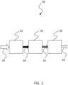
FIG. 1 , acompressor system 50 is illustrated which includes acompressor 52 capable of providing compression to acompressible fluid 54 such as, but not limited to, air. Although examples described herein will make reference to air or compressed air, it will be appreciated that thecompressor system 50 can be used to pressurize other types of compressible gases. Thecompressor 52 can take any variety of forms including but not limited to contact cooled screw compressors. Such contact cooled screw compressors can use any type of lubricant such as but not limited to oil. - In some examples the
compressor system 50 can further include one ormore devices air 60 provided by thecompressor 52. In general, thecompressor 52 can be in fluid communication one or more filter(s), air dryer(s), etc such as but not limited to thedevices 56 and/or 58 depicted inFIG. 1 . In one non-limited example, thecompressor 52 can be coupled with aprimary oil filter 56 and asecondary oil filter 58. Such aprimary oil filter 56 can be of a centrifugal separator type to remove unwanted oil from the mixed flow of compressed air andoil 60, while thesecondary oil filter 56 can be a device that uses a coalescence filter to further remove oil from theflow 62 to produce acleaner flow 64. It will be appreciated that in some forms thecoalescence filter 58 might be the only filter used in acompressor system 50, but can still be coupled with further devices for removing unwanted material from the flow of compressedair 60. - Turning now to
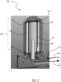
FIGS. 2 and3 , one example of afilter 58 is depicted which takes the form of a coalescence filter system. It will be appreciated that although the example depicted inFIG. 2 is illustrated usingreference numeral 58, some systems may not include thedevice 56, or may include adevice 56 but not of the filtering type. No limitation is hereby intended that thefilter 58 must be a secondary filter in any type of system that includes the features of the filter.Filter system 58 includes areplaceable filter cartridge 66 having afilter media 68 disposed between aspinner 70 andend cap 72. In accordance with the present invention, thereplaceable cartridge 66 is inserted around amesh filter member 74 which is situated upon amesh holder 76. Ahousing 78 is used to enclose thefilter cartridge 66 and form various flow passages for the conveyance of a mixed flow of compressed fluid and oil as well as a filtered flow. Thehousing 78 can be attached to the base of the unit through a threaded or bayonet type connection, but other connection types are also contemplated. In one form thehousing 78 is attached using a quarter-turn. - As a mixed flow of
compressed air 62 enters thefilter system 58 it travels down a conduit and it turned to flow upward and between themesh holder 76 and thehousing 78. As air is routed between themesh holder 76 and thehousing 78 is passes through thespinner 70 which imparts a circumferential rotation to theflow 62. Suitable space is provided between thefilter media 68 and thehousing 78 to permit swirling passage of theflow 62 and adequate distribution of theflow 62. In some forms, a circularshaped filter media 68 and inner surface of thehousing 78 aid in the swirling motion of air. The mixed flow then traverses through thefilter media 68 of thereplacement cartridge 66 as well as traverses through themesh filter element 74 before being received within an open interior of thereplaceable filter cartridge 66. Astandpipe 80 can be provided to extend away from themesh holder 76 and is used to receive the flow of compressedfluid 64 after some or all of oil in the mixedflow 62 has been extracted via thefilter media 68 andmesh filter element 74. Thestandpipe 80 can be an integral portion of themesh holder 76, or can be a separate part that is integrated with themesh holder 76. The flow received into thestandpipe 80 is then directed out of thefilter system 58 through a passage. - As contemplated herein, the
filter cartridge 66 can be made as a replaceable module that can be manipulated/handled as a unitary whole as it is inserted into afilter system 58. It is envisioned that such a modular, stand-alone component can include thefilter media 68 and at least one of thespinner 70 andend cap 72. In some forms the stand-alone cartridge 66 can include additional components beyond the filter media and either or both of thespinner 70 andend cap 72. - The
filter media 68 can take on a variety of forms suitable to coalesce oil from the mixedstream 62 of compressed fluid and oil. In some examples thefilter media 68 can be made of paper made using any variety of fiber material. In one form thefilter media 68 can be made of rolled paper, but other forms are also contemplated such as pleated, etc. - Turning now to
FIGS. 5a and 5b , and with continued reference toFIGS. 1-3 , one example of thespinner 70 is depicted. In accordance with the present invention, the spinner includes aninner ring 82,outer ring 84, andairflow members 86 extending between the inner and outer rings. Theairflow members 86 can take on any variety of forms including vanes, orifices, etc. In the form of vanes theairflow members 86 can extend between respective leading and trailing edges in any variety of manners. For example, theairflow members 86 can extend in a straight line between its leading and trailing edges. In some forms a camber line between the leading and trailing edges can be curved. In certain forms the camber line can be continuous or non-continuous. In still other forms theairflow members 86 can extend in a segmented manner between leading and trailing edges. In short, any variety of shapes are contemplated for theairflow members 86 of the spinner. - The
airflow members 86 can furthermore impart any degree of circumferential motion of fluid flowing therethrough. In some forms theairflow members 86 can impart a relatively higher degree of circumferential motion than axial motion of the fluid, while in other forms theairflow members 86 can impart a relatively higher degree of axial motion than circumferential motion. In still other forms the circumferential and axial components of fluid velocity can be the same. As will be understood, whether or not theairflow members 86 take the form of vanes, orifices, etc., one ormore airflow passages 88 will be formed in the spinner to traverse from an upstream side of the spinner to a downstream side, As such, the shape of the passages (which can be formed by neighboring vanes, for example) can dictate the degree of circumferential motion relative to the degree of axial motion of the air exiting the downstream side of thespinner 70. - Although the
spinner 70 in the illustrated example includes bothinner ring 82 andouter ring 86, in other forms thespinner 70 can include fewer components. For example, thespinner 70 can have theouter ring 84 andairflow members 86, but lack theinner ring 82. In such a form theairflow members 86 can be individually affixed to the filter media. In other forms thespinner 70 can have theinner ring 82 andairflow members 86 but otherwise lack anouter ring 84. - The
spinner 70 can be attached to thefilter media 68 via any suitable manner, whether mechanical, bonding, or otherwise. In some forms thespinner 70 can be attached using chemical bonding such as through an adhesive process such as gluing or epoxying. Epoxy can include can be any of a basic component or cured end products of epoxy resins, as well as represent the epoxide functional group. Any suitable type of adhesive is contemplated. - Turning now to
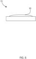
FIG. 6 , and with continued reference toFIGS. 1-3 , one example of theend cap 72 is depicted. Theend cap 72 can be used to enclose the open interior of thefilter media 68. The end cap can include an annular slot defined between aninside wall 88 and outsidewall 90 which can be used to receive thefilter media 68 and in some examples also receive themesh filter element 74. Either or both of theinside wall 88 and outsidewall 90 can extend uninterrupted around the periphery of thefilter media 68, but in some forms either or both of theinside wall 88 and outsidewall 90 can include a broken configuration. The size of the annular slot between theinside wall 88 and outsidewall 90 can receive both of thefilter media 68 andmesh filter element 74. In some forms theinside wall 88 can include a chamfer or sloped edge to pilot themesh filter element 74 when thefilter cartridge 66 is inserted onto themesh filter element 74. - As illustrated in
FIG. 3 , thehousing 78 can include aprotuberance 92 which can be used to urge thefilter cartridge 66 into a seated position upon themesh holder 76. In alternative and/or additional examples, theprotuberance 92 can be located on theend cap 72 as depicted inFIG. 6 . Theprotuberance 92 can take on any suitable form and is generally located within the outer periphery of theend cap 72. Wherever it is located, theprotuberance 92 can one or more raised surfaces which are typically blunted in shape as shown. - The
end cap 72 70 can be attached to thefilter media 68 via any suitable manner, whether mechanical, bonding, or otherwise. In some forms theend cap 72 can be attached using chemical bonding such as through an adhesive process such as gluing or epoxying. Epoxy can include can be any of a basic component or cured end products of epoxy resins, as well as represent the epoxide functional group. Any suitable type of adhesive is contemplated. - The material type of each of the
filter media 68,spinner 70, andend cap 72, can all be different, but in some forms one or more of the materials used for the filter media, spinner, and end cap can be the same. Reference will be made immediately below to the type of material thefilter media 68 is made of and its capability of being disposed of through burning (e.g. through an incineration process such as waste treatment incineration). The discussion below related to the incineration of the filter media material is also applicable to the material used in the construction of the spinner and end cap. In some examples the material type of thespinner 70 and/orend cap 72 are different from the filter media material, but it will nevertheless be understood that the description below of waste disposal of the filter media also applies to thespinner 70 andend cap 72 as well. Thefilter media 68 can be made of a filter media material that can be burned, such as through combustion, in a process that can be characterized by a high temperature exothermic redox chemical reaction between a fuel and an oxidant. Thermal oxidation of the filter media material can include a combustion process such as deflagration or any other high-temperature exothermic reaction between a fuel and oxidant. Thefilter media 68 can act as the fuel to be thermally oxidized with an oxidant such as but not limited to air. It is contemplated that in some examples the filter media material can be consumed via thermal oxidation and provide a greater thermal energy output as a result of the thermal oxidation than the amount of energy input to provide the elevated temperatures needed for the thermal oxidation to occur. - It is contemplated that any or all of the filter media material, spinner material, and end cap material are made of a material that can be disposed of via incineration in a waste treatment process. In some examples of the material types incineration can convert the components (filter media, spinner, and/or end cap) into ash, flue gas, and heat. The material type can provide energy recovery during the incineration process. It is contemplated that the material type used in some examples of any of the components to be incinerated meets with applicable regulations of material type suitable for incineration, whether those regulations are promulgated by the United States Environmental Protection Agency, among any potential others. Various types of incineration processes are contemplated, including burn piles, burn barrels, moving grates, fixed grate, rotary kiln, fluidized bed, and specialized incineration.
- In one form the spinner material is contemplated to be made of plastic, such as but not limited to organic polymers that can be of a thermoplastic or thermosetting type polymer. It is contemplated that the wide range of plastic materials suitable for use as the spinner material can be thermally oxidized in an incineration process as mentioned above anywhere in a temperature range of between about 200°C (390°F) to about 600°C (1100°F) but other ranges may be useful for other plastic-like materials.
- In one form the end cap material is contemplated to be made of rubber or other suitable type of elastomer, such as but not limited to those materials that include polyisoprenes or organic compound isoprenes. It is contemplated that the wide range of rubber materials suitable for use as the end cap material can be thermally oxidized in an incineration process as mentioned above anywhere in a temperature range of between about 250°C (480°F) to about 350°C (662°F) but other ranges may be useful for other rubber-like materials.
- The
mesh filter element 74 can take on a variety of forms and be made from a variety of materials. In one examples themesh filter element 74 can be a wire mesh construction made of any suitable metallic wire fiber. The mesh construction can be woven or non-woven, depending on the application. Such non-woven construction can be made from short and long fibers which can be bonded together using chemical, mechanical, heat, or solvent treatments. The non-woven examples can be flat or tufted porous sheets. - Turning now to
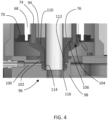
FIG. 4 , and with continued reference toFIGS. 1-3 , one form of amesh holder 76 is depicted. Themesh holder 76 can include awide end 94 and anarrow end 96 disposed opposite thewide end 94 which generally takes a frusto-conical shape similar to a truncated cone. Themesh holder 76 is coupled with a combo-block 98 which includes adrain line 100 which carries oil away from themesh holder 76. The combo-block 98 can be any suitable device that provides a seat for themesh holder 76 and that receives collected oil from themesh holder 76. Themesh holder 76 can be coupled to the combo-block 100 via a compression fit via one or more seals such as but not limited to o-rings 102. Further details of the coupling of themesh holder 76 and combo-block 100 are described further below. - The
mesh holder 76 includes anannular groove 104 defined between aninner wall 106 andouter wall 108. Theannular groove 104 is structured to receive themesh filter element 74. Theouter wall 102 can be sized larger than theinner wall 100 such that oil that collects in theannular groove 104 is discouraged from radially escaping themesh holder 76 and draining down the side. Themesh holder 76 also includes one ormore drain lines 110 in fluid communication with theannular groove 104 to carry away oil that has been collected as a result of the filtering. - Oil collected in the
annular groove 104 can flow throughdrain line 110 to agallery 112 located between thestand pipe 80 and themesh holder 76. Thegallery 112 can be any shape and size and in one form is annular in shape. Thegallery 112 is in fluid communication with thedrain line 100 of the combo-block 98.Various seals drain line 100.Seals - The
filter cartridge 66 can interface with themesh holder 76 via thespinner 70, although other engagement interfaces are also contemplated. As shown inFIG. 4 , the spinner can include a stepped feature to fit upon the outer edge of themesh holder 76 near theoutside wall 90. Theoutside wall 90 includes a complementary stepped feature to receive thespinner 70. - Although the
mesh holder 76, stand-pipe 80, and combo-block 98 are depicted as separate elements that together help support and drain oil away from thefilter cartridge 66, in some examples two or more of these components and be made integral with each other. - It should be understood that while the use of words such as preferable, preferably, preferred or more preferred utilized in the description above indicate that the feature so described may be more desirable, it nonetheless may not be necessary and examples lacking the same may be contemplated as within the scope of the invention, the scope being defined by the claims that follow. In reading the claims, it is intended that when words such as "a," "an," "at least one," or "at least one portion" are used there is no intention to limit the claim to only one item unless specifically stated to the contrary in the claim. When the language "at least a portion" and/or "a portion" is used the item can include a portion and/or the entire item unless specifically stated to the contrary. Unless specified or limited otherwise, the terms "mounted," "connected," "supported," and "coupled" and variations thereof are used broadly and encompass both direct and indirect mountings, connections, supports, and couplings. Further, "connected" and "coupled" are not restricted to physical or mechanical connections or couplings.
Claims (18)
- An apparatus comprising:a filter housing (78);a mesh holder (76) disposed within the filter housing (78) such that a flow passage is defined between the mesh holder and the filter housing;a mesh filter member (74) supported by the mesh holder (76); anda replaceable filter cartridge (66) having an open interior and being removably connected to the mesh holder (76), the replaceable filter cartridge inserted around the mesh filter member (74), the replaceable filter cartridge having a filter media (68) that extends in an axial direction and is disposed between an annular-shaped airflow spinner (70) and an end cap (72), and wherein the annular-shaped airflow spinner is affixed to an outer surface of the filter media such that the replaceable filter cartridge is modular and can be handled as a unitary whole as it is inserted into the filter housing (78), the annular-shaped airflow spinner including an inner ring (82), an outer ring (84), and a plurality of airflow members (86) extending between the inner ring and the outer ring, the plurality of airflow members defining a plurality of passages (88), the plurality of airflow members being structured to impart a circumferential component of swirl to a passing flow of fluid in the flow passage when the replaceable filter cartridge (66) is installed in the filter housing (78), the flow of fluid subsequently traversing through the filter media (68) and mesh filter member (74) into the open interior of the filter cartridge (66).
- The apparatus of claim 1, wherein the annular-shaped airflow spinner (70) is bonded to the filter media (68).
- The apparatus of claim 1 or 2, wherein the plurality of airflow members (86) are airflow vanes each having a leading edge and a trailing edge, each of the plurality of passages defined by a top surface of one of the airflow vanes and a bottom surface of an adjacent one of the airflow vanes.
- The apparatus of any preceding claim, wherein the spinner material thermally oxidizes at a temperature below 600°C (1100°F).
- The apparatus of any of the preceding claims, wherein the annular-shaped airflow spinner (70) forms an abutment surface structured to seat against a filter canister housing, and wherein the annular-shaped airflow spinner is chemically bonded to the filter media (68).
- The apparatus of any of the preceding claims, wherein an end cap (72) is affixed to the filter media at a second end to seal an open interior of the filter media, the end cap including a recess to receive the filter media (68), the recess being large enough to accommodate a complementary mesh filter (76) when inserted into the open interior of the filter media.
- The apparatus of claim 6, wherein the end cap (72) is bonded to the filter media (68) at the second end, and wherein the end cap includes an exterior protrusion extending from a top surface of the cap in a direction away from the open interior, the exterior protrusion constructed to engage the filter housing.
- The apparatus of claim 6, wherein the filter media (68) has a circular cross section, the filter media being structured to remove lubricant entrained in a flow of compressed gas, the end cap being connected at a first axial end of the filter media to enclose an open interior of the filter media, the end cap (72) having an arcing groove formed on an inside surface located interior of the filter media, the arcing groove defined between an inner groove wall and an outer groove wall, a distance between the inner and outer groove walls sized to fit the filter media, the end cap defined by a peripheral boundary and having a blunted protrusion extending from an interior of the peripheral boundary, the blunted protrusion structured to contact an inner surface of the filter housing to provide a positive pressure to the filter cartridge.
- The apparatus of claim 8, wherein the end cap (72) includes a single blunted protrusion (92) located radially inward from an outer periphery of the end cap.
- The apparatus of claim 8 or 9, the blunted protrusion taking the form of a nub having a rounded contact point, and wherein the blunted protrusion extends from the center of the end cap (72).
- The apparatus of any of claims 8 to 10, wherein the end cap (72) is chemically bonded to the filter media, and wherein the end cap is made from an end cap material having a composition that will exothermically oxidize under elevated temperatures.
- The apparatus of any of claims 8 to 11, wherein the arcing groove is an annular shaped groove, and wherein the end cap (72) is chemically bonded to the filter media.
- The apparatus of claim 12, wherein the distance between the inner and outer groove walls is sized to accommodate a secondary filter media in addition to the filter media chemically bonded to the end cap (72).
- The apparatus of any of claims 8 to 13, wherein the spinner (70) is affixed to a second axial end of the filter media (68) opposite the first axial end, wherein the spinner is affixed via chemical bonding, and wherein the filter cartridge (66) with end cap (72) and spinner (70) are constructed as a modular device capable of being handled as a unitary whole as the filter cartridge is inserted into a filter housing.
- The apparatus of claim 14, wherein the filter media (68) is made of a material that combusts under elevated temperatures, wherein the end cap (72) is made of a material that combusts under elevated temperatures, and wherein the spinner (70) is made of a material that combusts under elevated temperatures.
- An oil filter assembly structured to remove oil from a mixed flow of compressed air and oil, the oil filter assembly comprising:an apparatus according to any preceding claim; anda combo-block base (98) which includes a combo-block oil passage for the receipt of oil removed from the mixed flow by action of the oil filter assembly;wherein the mesh holder (76) is a frusto-conical shaped mesh holder having an open interior extending between a first base of the frusto-conical shape and an opposing second base of the frusto-conical shape, the mesh holder further including an annular well defined in a first end (94) of the mesh holder and which is structured to receive the mesh filter member (74), the mesh holder further including at least one oil passage that extends from the annular well to the open interior; and the oil filter assembly further comprising a stand-pipe (80) extending from the open interior and away from the first end.
- The oil filter assembly of claim 16, wherein the stand-pipe (80) is inserted as a separate component into the open interior of the mesh holder, wherein the mesh holder is coupled to the combo-block base (98) via an o-ring compression fitting, and wherein an annular space is formed between an outside of the stand-pipe and an interior wall of the mesh holder that defines the open interior, the annular space in communication with the at least one oil passage.
- The oil filter assembly of claim 16 or claim 17, wherein the mesh holder further includes an outer wall defining the annular well, the outer wall extending away from the first end to form a dam structured to discourage oil from flowing radially outward away from the mesh holder, and wherein the oil filter assembly further includes a removable housing having an interior surface structured to abut a replaceable oil filter element seated against the mesh holder.
Priority Applications (1)
| Application Number | Priority Date | Filing Date | Title |
|---|---|---|---|
| EP24164121.6A EP4360733A3 (en) | 2018-12-21 | 2019-12-20 | Filter system and replaceable filter cartridge |
Applications Claiming Priority (1)
| Application Number | Priority Date | Filing Date | Title |
|---|---|---|---|
| US16/229,739 US11331610B2 (en) | 2018-12-21 | 2018-12-21 | Filter system and replaceable filter cartridge |
Related Child Applications (1)
| Application Number | Title | Priority Date | Filing Date |
|---|---|---|---|
| EP24164121.6A Division EP4360733A3 (en) | 2018-12-21 | 2019-12-20 | Filter system and replaceable filter cartridge |
Publications (3)
| Publication Number | Publication Date |
|---|---|
| EP3669967A2 EP3669967A2 (en) | 2020-06-24 |
| EP3669967A3 EP3669967A3 (en) | 2020-08-26 |
| EP3669967B1 true EP3669967B1 (en) | 2024-04-03 |
Family
ID=69005415
Family Applications (2)
| Application Number | Title | Priority Date | Filing Date |
|---|---|---|---|
| EP19219020.5A Active EP3669967B1 (en) | 2018-12-21 | 2019-12-20 | Filter system and replaceable filter cartridge |
| EP24164121.6A Pending EP4360733A3 (en) | 2018-12-21 | 2019-12-20 | Filter system and replaceable filter cartridge |
Family Applications After (1)
| Application Number | Title | Priority Date | Filing Date |
|---|---|---|---|
| EP24164121.6A Pending EP4360733A3 (en) | 2018-12-21 | 2019-12-20 | Filter system and replaceable filter cartridge |
Country Status (3)
| Country | Link |
|---|---|
| US (3) | US11331610B2 (en) |
| EP (2) | EP3669967B1 (en) |
| CN (2) | CN111420487A (en) |
Families Citing this family (2)
| Publication number | Priority date | Publication date | Assignee | Title |
|---|---|---|---|---|
| WO2017092795A1 (en) * | 2015-12-01 | 2017-06-08 | Ateliers Busch S.A. | Vacuum pump with filtering element |
| WO2024099730A1 (en) * | 2022-11-07 | 2024-05-16 | Altair (UK) Limited | Improved pulse filter with integral support |
Family Cites Families (19)
| Publication number | Priority date | Publication date | Assignee | Title |
|---|---|---|---|---|
| US3036711A (en) | 1959-01-06 | 1962-05-29 | Purolator Products Inc | Filter unit |
| US4035306A (en) | 1975-06-23 | 1977-07-12 | Sheller-Globe Corporation | Removable cartridge filter |
| DE8501736U1 (en) * | 1985-01-24 | 1985-08-22 | Filterwerk Mann & Hummel Gmbh, 7140 Ludwigsburg | Device for separating oil droplets from air |
| US5028318A (en) | 1989-04-19 | 1991-07-02 | Aeroquip Corporation | Cyclonic system for separating debris particles from fluids |
| US5066391A (en) | 1990-08-22 | 1991-11-19 | Faria Manuel S | Reusable liquid filter assembly |
| US5170640A (en) | 1991-03-04 | 1992-12-15 | Carrier Corporation | Oil separator |
| US5548893A (en) | 1995-03-20 | 1996-08-27 | Koelfgen; Douglas F. | Spin-on oil filter replacement element |
| US6099606A (en) * | 1998-03-19 | 2000-08-08 | Donaldson Company, Inc. | Air filtration arrangements having spacer constructions |
| DE19908377A1 (en) | 1999-02-26 | 2000-08-31 | Schlafhorst & Co W | Filter assembly for suction system at open-end spinner has filter chambers divided into main and reserve chambers with selective underpressure for cleaning and normal pressure for spinning |
| DE10233012A1 (en) * | 2002-07-20 | 2004-02-05 | Mann + Hummel Gmbh | Separator for cleaning a fluid flow |
| CN1774578A (en) * | 2003-04-16 | 2006-05-17 | 陶氏环球技术公司 | System for purifying and monitoring the condition of lubricant fluid in compressors and other equipement |
| US7326266B2 (en) | 2003-10-31 | 2008-02-05 | Flair Corporation | Coalescing type filter apparatus and method |
| GB0417458D0 (en) | 2004-08-05 | 2004-09-08 | Domnick Hunter Ltd | Filter assembly |
| CN102619590A (en) * | 2005-10-28 | 2012-08-01 | 唐纳森公司 | Aerosol separator and method of use |
| DE102008046499A1 (en) * | 2008-09-09 | 2010-03-18 | Mann + Hummel Gmbh | Filter with drainage connection |
| DE102011108061A1 (en) | 2011-07-21 | 2013-01-24 | Mann + Hummel Gmbh | Fluid filter assembly and filtering method |
| DE102013015052B4 (en) | 2013-09-12 | 2015-10-15 | Mann + Hummel Gmbh | Cyclone filter device |
| DE102016006095B4 (en) | 2015-07-16 | 2023-05-25 | Mann+Hummel Gmbh | Separation module, line module and venting device |
| DE102015011225A1 (en) | 2015-08-27 | 2017-03-02 | Rt-Filtertechnik Gmbh | separating |
-
2018
- 2018-12-21 US US16/229,739 patent/US11331610B2/en active Active
-
2019
- 2019-12-20 CN CN201911329027.4A patent/CN111420487A/en active Pending
- 2019-12-20 EP EP19219020.5A patent/EP3669967B1/en active Active
- 2019-12-20 EP EP24164121.6A patent/EP4360733A3/en active Pending
- 2019-12-20 CN CN202210604128.3A patent/CN114797325A/en active Pending
-
2022
- 2022-03-21 US US17/699,556 patent/US11865481B2/en active Active
-
2023
- 2023-11-30 US US18/524,410 patent/US20240165550A1/en active Pending
Also Published As
| Publication number | Publication date |
|---|---|
| CN114797325A (en) | 2022-07-29 |
| US11865481B2 (en) | 2024-01-09 |
| EP3669967A3 (en) | 2020-08-26 |
| EP4360733A3 (en) | 2024-05-22 |
| US20200197849A1 (en) | 2020-06-25 |
| CN111420487A (en) | 2020-07-17 |
| US11331610B2 (en) | 2022-05-17 |
| US20220280893A1 (en) | 2022-09-08 |
| EP3669967A2 (en) | 2020-06-24 |
| EP4360733A2 (en) | 2024-05-01 |
| US20240165550A1 (en) | 2024-05-23 |
Similar Documents
| Publication | Publication Date | Title |
|---|---|---|
| US20240165550A1 (en) | Filter system and replaceable filter cartridge | |
| US4842737A (en) | Filter assembly with an expandable shell | |
| EP1996309B1 (en) | Filter with drained jacket | |
| CN102316958A (en) | Filter element and filter system | |
| EP2451551B1 (en) | Dual stage filtration with barrier for fuel water separation | |
| CN101772370B (en) | Filter assembly | |
| RU2700058C2 (en) | Bypass cover and method of fluid medium directing through filter | |
| US20100294707A1 (en) | Multi-stage filter cartridge with snap fit filters | |
| US8540805B2 (en) | Filter assembly for use in a turbine system | |
| US20120292243A1 (en) | Filter arrangments and filter apparatuses which include filter arrangements | |
| EP2949374B1 (en) | Filter elements and methods for filtering fluids | |
| US20060090431A1 (en) | Filter assembly with combination filter element | |
| PL237677B1 (en) | Fuel filter element, filter assembly and method for producing the filter element | |
| EP3826750B1 (en) | Radial seal for spin-on filter | |
| US4200444A (en) | Filters | |
| CA2285288A1 (en) | Filter cartridge and filter arrangement | |
| US20240058734A1 (en) | Filter assemblies with combined axial and radial sealing | |
| EP3415217B1 (en) | Filter assembly with a connector for joining pleated filter sections | |
| WO2023009639A1 (en) | Filter cartridge with expandable endplate seal | |
| WO2023204998A1 (en) | Filter assembly with floating seal interface |
Legal Events
| Date | Code | Title | Description |
|---|---|---|---|
| PUAI | Public reference made under article 153(3) epc to a published international application that has entered the european phase |
Free format text: ORIGINAL CODE: 0009012 |
|
| STAA | Information on the status of an ep patent application or granted ep patent |
Free format text: STATUS: THE APPLICATION HAS BEEN PUBLISHED |
|
| AK | Designated contracting states |
Kind code of ref document: A2 Designated state(s): AL AT BE BG CH CY CZ DE DK EE ES FI FR GB GR HR HU IE IS IT LI LT LU LV MC MK MT NL NO PL PT RO RS SE SI SK SM TR |
|
| AX | Request for extension of the european patent |
Extension state: BA ME |
|
| PUAL | Search report despatched |
Free format text: ORIGINAL CODE: 0009013 |
|
| AK | Designated contracting states |
Kind code of ref document: A3 Designated state(s): AL AT BE BG CH CY CZ DE DK EE ES FI FR GB GR HR HU IE IS IT LI LT LU LV MC MK MT NL NO PL PT RO RS SE SI SK SM TR |
|
| AX | Request for extension of the european patent |
Extension state: BA ME |
|
| RIC1 | Information provided on ipc code assigned before grant |
Ipc: B01D 46/00 20060101AFI20200720BHEP Ipc: B01D 46/24 20060101ALI20200720BHEP |
|
| STAA | Information on the status of an ep patent application or granted ep patent |
Free format text: STATUS: REQUEST FOR EXAMINATION WAS MADE |
|
| 17P | Request for examination filed |
Effective date: 20210225 |
|
| RBV | Designated contracting states (corrected) |
Designated state(s): AL AT BE BG CH CY CZ DE DK EE ES FI FR GB GR HR HU IE IS IT LI LT LU LV MC MK MT NL NO PL PT RO RS SE SI SK SM TR |
|
| RAP1 | Party data changed (applicant data changed or rights of an application transferred) |
Owner name: INGERSOLL-RAND INDUSTRIAL U.S., INC. |
|
| STAA | Information on the status of an ep patent application or granted ep patent |
Free format text: STATUS: EXAMINATION IS IN PROGRESS |
|
| 17Q | First examination report despatched |
Effective date: 20210707 |
|
| GRAP | Despatch of communication of intention to grant a patent |
Free format text: ORIGINAL CODE: EPIDOSNIGR1 |
|
| STAA | Information on the status of an ep patent application or granted ep patent |
Free format text: STATUS: GRANT OF PATENT IS INTENDED |
|
| INTG | Intention to grant announced |
Effective date: 20231109 |
|
| GRAS | Grant fee paid |
Free format text: ORIGINAL CODE: EPIDOSNIGR3 |
|
| GRAA | (expected) grant |
Free format text: ORIGINAL CODE: 0009210 |
|
| STAA | Information on the status of an ep patent application or granted ep patent |
Free format text: STATUS: THE PATENT HAS BEEN GRANTED |
|
| AK | Designated contracting states |
Kind code of ref document: B1 Designated state(s): AL AT BE BG CH CY CZ DE DK EE ES FI FR GB GR HR HU IE IS IT LI LT LU LV MC MK MT NL NO PL PT RO RS SE SI SK SM TR |
|
| REG | Reference to a national code |
Ref country code: CH Ref legal event code: EP |
|
| REG | Reference to a national code |
Ref country code: IE Ref legal event code: FG4D |
|
| REG | Reference to a national code |
Ref country code: DE Ref legal event code: R096 Ref document number: 602019049387 Country of ref document: DE |