EP3669763B1 - Appareil et procédé d'estimation d'informations cardiovasculaires - Google Patents
Appareil et procédé d'estimation d'informations cardiovasculaires Download PDFInfo
- Publication number
- EP3669763B1 EP3669763B1 EP19216050.5A EP19216050A EP3669763B1 EP 3669763 B1 EP3669763 B1 EP 3669763B1 EP 19216050 A EP19216050 A EP 19216050A EP 3669763 B1 EP3669763 B1 EP 3669763B1
- Authority
- EP
- European Patent Office
- Prior art keywords
- pulse wave
- point
- wave signal
- maximum
- cardiovascular information
- Prior art date
- Legal status (The legal status is an assumption and is not a legal conclusion. Google has not performed a legal analysis and makes no representation as to the accuracy of the status listed.)
- Active
Links
- 230000002526 effect on cardiovascular system Effects 0.000 title claims description 197
- 238000000034 method Methods 0.000 title claims description 55
- 230000001174 ascending effect Effects 0.000 claims description 73
- 230000036772 blood pressure Effects 0.000 claims description 18
- 210000004369 blood Anatomy 0.000 claims description 14
- 239000008280 blood Substances 0.000 claims description 14
- 230000036581 peripheral resistance Effects 0.000 claims description 14
- 230000002792 vascular Effects 0.000 claims description 10
- WQZGKKKJIJFFOK-GASJEMHNSA-N Glucose Natural products OC[C@H]1OC(O)[C@H](O)[C@@H](O)[C@@H]1O WQZGKKKJIJFFOK-GASJEMHNSA-N 0.000 claims description 5
- 239000008103 glucose Substances 0.000 claims description 5
- UFTFJSFQGQCHQW-UHFFFAOYSA-N triformin Chemical compound O=COCC(OC=O)COC=O UFTFJSFQGQCHQW-UHFFFAOYSA-N 0.000 claims description 5
- 238000010586 diagram Methods 0.000 description 36
- 238000004891 communication Methods 0.000 description 32
- 230000006870 function Effects 0.000 description 6
- 238000005259 measurement Methods 0.000 description 6
- 230000004044 response Effects 0.000 description 6
- 230000000747 cardiac effect Effects 0.000 description 5
- 230000035488 systolic blood pressure Effects 0.000 description 5
- 230000000694 effects Effects 0.000 description 4
- 101100083446 Danio rerio plekhh1 gene Proteins 0.000 description 3
- 238000001914 filtration Methods 0.000 description 3
- 238000010606 normalization Methods 0.000 description 3
- 238000004364 calculation method Methods 0.000 description 2
- 230000036996 cardiovascular health Effects 0.000 description 2
- 230000001413 cellular effect Effects 0.000 description 2
- 238000004590 computer program Methods 0.000 description 2
- 238000010276 construction Methods 0.000 description 2
- 238000013500 data storage Methods 0.000 description 2
- 230000004882 diastolic arterial blood pressure Effects 0.000 description 2
- 230000004069 differentiation Effects 0.000 description 2
- 230000014509 gene expression Effects 0.000 description 2
- 230000003287 optical effect Effects 0.000 description 2
- 210000005259 peripheral blood Anatomy 0.000 description 2
- 239000011886 peripheral blood Substances 0.000 description 2
- 230000003068 static effect Effects 0.000 description 2
- 230000004873 systolic arterial blood pressure Effects 0.000 description 2
- 230000032683 aging Effects 0.000 description 1
- 210000003423 ankle Anatomy 0.000 description 1
- QVGXLLKOCUKJST-UHFFFAOYSA-N atomic oxygen Chemical compound [O] QVGXLLKOCUKJST-UHFFFAOYSA-N 0.000 description 1
- 230000005540 biological transmission Effects 0.000 description 1
- 230000001419 dependent effect Effects 0.000 description 1
- 230000035487 diastolic blood pressure Effects 0.000 description 1
- 238000005516 engineering process Methods 0.000 description 1
- 210000000245 forearm Anatomy 0.000 description 1
- 238000001361 intraarterial administration Methods 0.000 description 1
- 210000005240 left ventricle Anatomy 0.000 description 1
- 238000004519 manufacturing process Methods 0.000 description 1
- 238000012986 modification Methods 0.000 description 1
- 230000004048 modification Effects 0.000 description 1
- 229910052760 oxygen Inorganic materials 0.000 description 1
- 239000001301 oxygen Substances 0.000 description 1
- 230000010412 perfusion Effects 0.000 description 1
- 238000012545 processing Methods 0.000 description 1
- 238000011160 research Methods 0.000 description 1
- 210000005245 right atrium Anatomy 0.000 description 1
- 238000002798 spectrophotometry method Methods 0.000 description 1
- 210000000689 upper leg Anatomy 0.000 description 1
- 230000000007 visual effect Effects 0.000 description 1
Images


Classifications
-
- A—HUMAN NECESSITIES
- A61—MEDICAL OR VETERINARY SCIENCE; HYGIENE
- A61B—DIAGNOSIS; SURGERY; IDENTIFICATION
- A61B5/00—Measuring for diagnostic purposes; Identification of persons
- A61B5/02—Detecting, measuring or recording pulse, heart rate, blood pressure or blood flow; Combined pulse/heart-rate/blood pressure determination; Evaluating a cardiovascular condition not otherwise provided for, e.g. using combinations of techniques provided for in this group with electrocardiography or electroauscultation; Heart catheters for measuring blood pressure
- A61B5/021—Measuring pressure in heart or blood vessels
- A61B5/02108—Measuring pressure in heart or blood vessels from analysis of pulse wave characteristics
- A61B5/02125—Measuring pressure in heart or blood vessels from analysis of pulse wave characteristics of pulse wave propagation time
-
- A—HUMAN NECESSITIES
- A61—MEDICAL OR VETERINARY SCIENCE; HYGIENE
- A61B—DIAGNOSIS; SURGERY; IDENTIFICATION
- A61B5/00—Measuring for diagnostic purposes; Identification of persons
- A61B5/02—Detecting, measuring or recording pulse, heart rate, blood pressure or blood flow; Combined pulse/heart-rate/blood pressure determination; Evaluating a cardiovascular condition not otherwise provided for, e.g. using combinations of techniques provided for in this group with electrocardiography or electroauscultation; Heart catheters for measuring blood pressure
- A61B5/021—Measuring pressure in heart or blood vessels
- A61B5/02108—Measuring pressure in heart or blood vessels from analysis of pulse wave characteristics
-
- A—HUMAN NECESSITIES
- A61—MEDICAL OR VETERINARY SCIENCE; HYGIENE
- A61B—DIAGNOSIS; SURGERY; IDENTIFICATION
- A61B5/00—Measuring for diagnostic purposes; Identification of persons
- A61B5/02—Detecting, measuring or recording pulse, heart rate, blood pressure or blood flow; Combined pulse/heart-rate/blood pressure determination; Evaluating a cardiovascular condition not otherwise provided for, e.g. using combinations of techniques provided for in this group with electrocardiography or electroauscultation; Heart catheters for measuring blood pressure
- A61B5/02007—Evaluating blood vessel condition, e.g. elasticity, compliance
-
- A—HUMAN NECESSITIES
- A61—MEDICAL OR VETERINARY SCIENCE; HYGIENE
- A61B—DIAGNOSIS; SURGERY; IDENTIFICATION
- A61B5/00—Measuring for diagnostic purposes; Identification of persons
- A61B5/02—Detecting, measuring or recording pulse, heart rate, blood pressure or blood flow; Combined pulse/heart-rate/blood pressure determination; Evaluating a cardiovascular condition not otherwise provided for, e.g. using combinations of techniques provided for in this group with electrocardiography or electroauscultation; Heart catheters for measuring blood pressure
- A61B5/021—Measuring pressure in heart or blood vessels
- A61B5/02108—Measuring pressure in heart or blood vessels from analysis of pulse wave characteristics
- A61B5/02116—Measuring pressure in heart or blood vessels from analysis of pulse wave characteristics of pulse wave amplitude
-
- A—HUMAN NECESSITIES
- A61—MEDICAL OR VETERINARY SCIENCE; HYGIENE
- A61B—DIAGNOSIS; SURGERY; IDENTIFICATION
- A61B5/00—Measuring for diagnostic purposes; Identification of persons
- A61B5/02—Detecting, measuring or recording pulse, heart rate, blood pressure or blood flow; Combined pulse/heart-rate/blood pressure determination; Evaluating a cardiovascular condition not otherwise provided for, e.g. using combinations of techniques provided for in this group with electrocardiography or electroauscultation; Heart catheters for measuring blood pressure
- A61B5/024—Detecting, measuring or recording pulse rate or heart rate
- A61B5/02416—Detecting, measuring or recording pulse rate or heart rate using photoplethysmograph signals, e.g. generated by infrared radiation
- A61B5/02427—Details of sensor
- A61B5/02433—Details of sensor for infrared radiation
-
- A—HUMAN NECESSITIES
- A61—MEDICAL OR VETERINARY SCIENCE; HYGIENE
- A61B—DIAGNOSIS; SURGERY; IDENTIFICATION
- A61B5/00—Measuring for diagnostic purposes; Identification of persons
- A61B5/02—Detecting, measuring or recording pulse, heart rate, blood pressure or blood flow; Combined pulse/heart-rate/blood pressure determination; Evaluating a cardiovascular condition not otherwise provided for, e.g. using combinations of techniques provided for in this group with electrocardiography or electroauscultation; Heart catheters for measuring blood pressure
- A61B5/024—Detecting, measuring or recording pulse rate or heart rate
- A61B5/02438—Detecting, measuring or recording pulse rate or heart rate with portable devices, e.g. worn by the patient
-
- A—HUMAN NECESSITIES
- A61—MEDICAL OR VETERINARY SCIENCE; HYGIENE
- A61B—DIAGNOSIS; SURGERY; IDENTIFICATION
- A61B5/00—Measuring for diagnostic purposes; Identification of persons
- A61B5/68—Arrangements of detecting, measuring or recording means, e.g. sensors, in relation to patient
- A61B5/6801—Arrangements of detecting, measuring or recording means, e.g. sensors, in relation to patient specially adapted to be attached to or worn on the body surface
- A61B5/6802—Sensor mounted on worn items
- A61B5/681—Wristwatch-type devices
-
- A—HUMAN NECESSITIES
- A61—MEDICAL OR VETERINARY SCIENCE; HYGIENE
- A61B—DIAGNOSIS; SURGERY; IDENTIFICATION
- A61B5/00—Measuring for diagnostic purposes; Identification of persons
- A61B5/72—Signal processing specially adapted for physiological signals or for diagnostic purposes
- A61B5/7203—Signal processing specially adapted for physiological signals or for diagnostic purposes for noise prevention, reduction or removal
-
- A—HUMAN NECESSITIES
- A61—MEDICAL OR VETERINARY SCIENCE; HYGIENE
- A61B—DIAGNOSIS; SURGERY; IDENTIFICATION
- A61B5/00—Measuring for diagnostic purposes; Identification of persons
- A61B5/72—Signal processing specially adapted for physiological signals or for diagnostic purposes
- A61B5/7235—Details of waveform analysis
- A61B5/7239—Details of waveform analysis using differentiation including higher order derivatives
-
- A—HUMAN NECESSITIES
- A61—MEDICAL OR VETERINARY SCIENCE; HYGIENE
- A61B—DIAGNOSIS; SURGERY; IDENTIFICATION
- A61B5/00—Measuring for diagnostic purposes; Identification of persons
- A61B5/72—Signal processing specially adapted for physiological signals or for diagnostic purposes
- A61B5/7235—Details of waveform analysis
- A61B5/7242—Details of waveform analysis using integration
-
- A—HUMAN NECESSITIES
- A61—MEDICAL OR VETERINARY SCIENCE; HYGIENE
- A61B—DIAGNOSIS; SURGERY; IDENTIFICATION
- A61B5/00—Measuring for diagnostic purposes; Identification of persons
- A61B5/72—Signal processing specially adapted for physiological signals or for diagnostic purposes
- A61B5/7235—Details of waveform analysis
- A61B5/7264—Classification of physiological signals or data, e.g. using neural networks, statistical classifiers, expert systems or fuzzy systems
-
- A—HUMAN NECESSITIES
- A61—MEDICAL OR VETERINARY SCIENCE; HYGIENE
- A61B—DIAGNOSIS; SURGERY; IDENTIFICATION
- A61B5/00—Measuring for diagnostic purposes; Identification of persons
- A61B5/02—Detecting, measuring or recording pulse, heart rate, blood pressure or blood flow; Combined pulse/heart-rate/blood pressure determination; Evaluating a cardiovascular condition not otherwise provided for, e.g. using combinations of techniques provided for in this group with electrocardiography or electroauscultation; Heart catheters for measuring blood pressure
- A61B5/026—Measuring blood flow
- A61B5/0261—Measuring blood flow using optical means, e.g. infrared light
Definitions
- Apparatuses and methods consistent with example embodiments relate to estimating cardiovascular information.
- US 2009 326 393 A1 provides systems and methods for non-invasive continuous blood pressure determination. It is disclosed that a PPG signal is received and locations of pulses within the PPG signal are identified. It is further disclosed that an area within a particular pulse is measured, wherein the area is of just the upstroke, downstroke or the entire pulse. It is further disclosed that the area is measured relative to a time-domain axis or a baseline of the pulse, wherein the pulse is split into multiple sections and the area of each section is measured. It is disclosed that the area of one portion of the pulse correspond to systolic blood pressure while the area of another portion correspond to diastolic blood pressure. It is further disclosed that empirical data is used to determine blood pressure from the measured area by applying calibration data measured by a suitable device.
- US 2006 074 322 A1 discloses a cuff-based method for the measurement of systolic blood pressure (SBP) by measuring photoplethysmographic (PPG) signals in peripheral blood vessels distal to the cuff and to a method for cuffless measurement of SBP by analyzing PPG signals in peripheral blood vessels, after suitable calibration by the cuff-based PPG method for the measurement of SBP
- SBP systolic blood pressure
- PPG photoplethysmographic
- JP 2000 300 526 A dislcoses a sphygmomanometer including a means for performing a calculation using information and a means for determining a blood pressure using the calculation result by this means, and a means for extracting a pulse wave during measurement and a means for extracting the pulse wave by this means.
- US 2009 024 012 A1 discloses a method and apparatus for measuring blood oxygen saturation by using spectrophotometry under a condition of low perfusion.
- WO 2018 172 958 A1 discloses a system for detecting vital physiological parameters of a subject.
- the system comprises a support means which can be associated with the subject and are connected to acquisition means configured to acquire synchronously an ECG signal and a PPG signal of the subject.
- the system further comprises a processing means which is connected to the acquisition means and comprises a systolic and diastolic arterial pressure module configured to calculate a vital physiological parameter related to systolic and diastolic arterial pressure
- JP 2000 237 153 A discloses a non-invasive continuous blood pressure estimation device for continuously estimating the intra-arterial blood pressure of a living body in a non-invasive manner, and continuously determining circulatory information obtained from the circulatory system of the living body in a non-invasive manner.
- One or more example embodiments provide an apparatus and method for estimating cardiovascular information by stably extracting cardiovascular feature values even when the quality of a bio-signal is poor.
- an apparatus for estimating cardiovascular information including: a memory storing instructions; a processor configured to execute the instructions to: obtain a pulse wave signal of an object; determine an area under a pulse wave signal and above a reference point on the pulse wave signal; and estimate cardiovascular information of the object based on the determined area of the pulse wave signal.
- the apparatus may further include a pulse wave signal obtainer including: a light source configured to emit light onto the object; and a photodetector configured to obtain the pulse wave signal by receiving the light returning from the object. wherein the pulse wave obtainer may be configured to provide the pulse wave signal to the processor.
- a pulse wave signal obtainer including: a light source configured to emit light onto the object; and a photodetector configured to obtain the pulse wave signal by receiving the light returning from the object.
- the pulse wave obtainer may be configured to provide the pulse wave signal to the processor.
- the processor may be further configured to execute the instructions to determine a time of a maximum point of a propagation wave component included in the pulse wave signal, and determine a point of the pulse wave signal, which corresponds to the time of the maximum point of the propagation wave component, as the reference point.
- the processor may be further configured to execute the instructions to determine a secondary differential signal of the pulse wave signal, determine a local minimum point in a predetermined interval of the secondary differential signal, and determine a point of the pulse wave signal, which corresponds to a time of the local minimum point, as the reference point.
- the processor may be further configured to execute the instructions to detect a pulse wave start point or a maximum ascending slope point from the pulse wave signal, and determine, as the reference point, one of a point after a first duration from the pulse wave start point, the maximum ascending slope point, and a point before or after a second duration from the maximum ascending slope point.
- the processor may be further configured to execute the instructions to detect, as the pulse wave start point, a minimum point of the pulse wave signal, or an intersection point between a tangent line at the maximum ascending slope point of the pulse wave signal and a height of the minimum point of the pulse wave signal.
- the processor may be further configured to execute the instructions to normalize the pulse wave signal or the determined area of the pulse wave signal based on at least one of a pulse wave signal amplitude corresponding to a time of a maximum point of a propagation wave component included in the pulse wave signal, a pulse wave signal amplitude at a point after a third duration from a pulse wave start point, a pulse wave signal amplitude at a maximum ascending slope point, a pulse wave signal amplitude at a point before or after a fourth duration from the maximum ascending slope point, and a duration of the pulse wave signal at a point higher than the reference point.
- the processor may be further configured to execute the instructions to remove an area of a propagation wave component, included in the determined area of the pulse wave signal, from the determined area of the pulse wave signal.
- the cardiovascular information may include at least one of blood pressure, vascular age, arterial stiffness, vascular compliance, blood glucose, blood triglyceride, and total peripheral resistance.
- the processor may be further configured to execute the instructions to estimate the cardiovascular information by using the determined area of the pulse wave signal as a cardiovascular feature value.
- the processor may be further configured to execute the instructions to estimate the cardiovascular information by using a cardiovascular information estimation model which defines a relationship between the cardiovascular feature value and the cardiovascular information.
- the processor may be further configured to execute the instructions to remove noise from the obtained pulse wave signal.
- a method of estimating cardiovascular information including: obtaining a pulse wave signal of an object; determining an area under a pulse wave signal and above a reference point on the pulse wave signal; and estimating cardiovascular information of the object based on the determined area of the pulse wave signal.
- the obtaining the pulse wave signal of the object may include: emitting light onto the object; and obtaining the pulse wave signal by receiving the light returning from the object.
- the determining the area of the pulse wave signal may include: determining a time of a maximum point of a propagation wave component included in the pulse wave signal; and determining a point of the pulse wave signal, which corresponds to the determined time of the maximum point of the propagation wave component, as the reference point.
- the determining the time of the maximum point of the propagation wave component may include: determining a secondary differential signal of the pulse wave signal; determining a local minimum point in a predetermined interval of the secondary differential signal; and determining a time of the determined local minimum point to be the time of the maximum point of the propagation wave component.
- the determining the area of the pulse wave signal may include: detecting a pulse wave start point or a maximum ascending slope point from the pulse wave signal; and determining, as the reference point, one of a point after a first duration from the pulse wave start point, the maximum ascending slope point, and a point before or after a second duration from the maximum ascending slope point.
- the detecting the pulse wave start point or the maximum ascending slope point may include detecting, as the pulse wave start point, a minimum point of the pulse wave signal, or an intersection point between a tangent line at the maximum ascending slope point of the pulse wave signal and a height of the minimum point of the pulse wave signal.
- the method may further include normalizing the pulse wave signal or the determined area of the pulse wave signal based on at least one of a pulse wave signal amplitude corresponding to a time of a maximum point of a propagation wave component included in the pulse wave signal, a pulse wave signal amplitude at a point after a third duration from a pulse wave start point, a pulse wave signal amplitude at a maximum ascending slope point, a pulse wave signal amplitude at a point before or after a fourth duration from the maximum ascending slope point, and a duration of the pulse wave signal at a point higher than the reference point.
- the method may further include removing an area of a propagation wave component, included in the determined area of the pulse wave signal, from the determined area of the pulse wave signal.
- the cardiovascular information may include at least one of blood pressure, vascular age, arterial stiffness, vascular compliance, blood glucose, blood triglyceride, and total peripheral resistance.
- the estimating the cardiovascular information may include estimating the cardiovascular information by using the determined area of the pulse wave signal as a cardiovascular feature value.
- the estimating the cardiovascular information may include estimating the cardiovascular information by using a cardiovascular information estimation model which defines a relationship between the cardiovascular feature value and the cardiovascular information.
- the method may include removing noise from the obtained pulse wave signal.
- an apparatus for estimating cardiovascular information including: a memory storing instructions; and a processor configured to execute the instructions to: obtain a pulse wave signal of an object; determine a secondary differential signal of the pulse wave signal; in response to detecting a local minimum point in a predetermined interval of the secondary differential signal, estimate cardiovascular information in a first operation mode; and in response to no local minimum point being detected in the predetermined interval of the secondary differential signal, estimate the cardiovascular information in a second operation mode different from the first operation mode.
- the apparatus may further include a pulse wave signal obtainer including: a light source configured to emit light onto the object; and a photodetector configured to obtain the pulse wave signal by receiving the light returning from the object, wherein the pulse wave obtainer may be configured to provide the pulse wave signal to the processor.
- a pulse wave signal obtainer including: a light source configured to emit light onto the object; and a photodetector configured to obtain the pulse wave signal by receiving the light returning from the object, wherein the pulse wave obtainer may be configured to provide the pulse wave signal to the processor.
- the processor may be further configured to execute the instructions to extract at least one feature value by analyzing the secondary differential signal, and estimate the cardiovascular information by using the extracted at least one feature value as a cardiovascular feature value.
- the processor may be further configured to execute the instructions to: determine a time of a maximum point of a propagation wave component and a time of a maximum point of a reflection wave component by analyzing the secondary differential signal; determine a pulse wave signal amplitude corresponding to each time of the maximum point of the propagation wave component and the maximum point of the reflection wave component; and extract the at least one feature value by combining at least one of the time of the maximum point of the propagation wave component, a pulse wave signal amplitude corresponding to the time of the maximum point of the propagation wave component, the time of the maximum point of the reflection wave component, and a pulse wave signal amplitude corresponding to the time of the maximum point of the reflection wave component.
- the processor may be further configured to execute the instructions to determine an area under the pulse wave signal and above a reference point on the pulse wave signal, and estimate the cardiovascular information of the object by using the determined area of the pulse wave signal as a cardiovascular feature value.
- the processor may be further configured to execute the instructions to detect a pulse wave start point or a maximum ascending slope point from the pulse wave signal, and determine, as the reference point, one of a point after a first duration from the pulse wave start point, the maximum ascending slope point, and a point before or after a second duration from the maximum ascending slope point.
- the processor may be further configured to execute the instructions to detect, as the pulse wave start point, a minimum point of the pulse wave signal, or an intersection point between a tangent line at the maximum ascending slope point of the pulse wave signal and a height of the minimum point of the pulse wave signal.
- the processor may be further configured to execute the instructions to normalize the pulse wave signal or the determined area of the pulse wave signal based on at least one of a pulse wave signal amplitude at the point after a first duration from a pulse wave start point, a pulse wave signal amplitude at a maximum ascending slope point, a pulse wave signal amplitude at a point before or after a second duration from the maximum ascending slope point, and a duration of the pulse wave signal at a point higher than the reference point.
- a method of estimating cardiovascular information including: obtaining a pulse wave signal of an object; determining a secondary differential signal of the pulse wave signal; in response to detecting a local minimum point in a predetermined interval of the secondary differential signal, estimating cardiovascular information in a first operation mode; and in response to no local minimum point being detected in the predetermined interval of the secondary differential signal, estimating the cardiovascular information in a second operation mode different from the first operation mode.
- the obtaining the pulse wave signal of the object may include: emitting light onto the object; and obtaining the pulse wave signal by receiving the light returning from the object.
- the estimating the cardiovascular information in the first operation mode may include: extracting at least one feature value by analyzing the secondary differential signal; and estimating the cardiovascular information by using the extracted at least one feature value as a cardiovascular feature value.
- the extracting the at least one feature value may include: determining a time of a maximum point of a propagation wave component and a time of a maximum point of a reflection wave component by analyzing the secondary differential signal; determining a pulse wave signal amplitude corresponding to each time of the maximum point of the propagation wave component and the maximum point of the reflection wave component; and extracting the at least one feature value by combining at least one of the time of the maximum point of the propagation wave component, a pulse wave signal amplitude corresponding to the time of the maximum point of the propagation wave component, the time of the maximum point of the reflection wave component, and a pulse wave signal amplitude corresponding to the time of the maximum point of the reflection wave component.
- the estimating the cardiovascular information in the second operation mode may include: determining an area under the pulse wave signal and above a reference point on the pulse wave signal; and estimating the cardiovascular information of the object by using the determined area of the pulse wave signal as a cardiovascular feature value.
- the determining the area of the pulse wave signal may include: detecting a pulse wave start point or a maximum ascending slope point from the pulse wave signal; and determining, as the reference point, one of a point after a first duration from the pulse wave start point, the maximum ascending slope point, and a point before or after a second duration from the maximum ascending slope point.
- the detecting the pulse wave start point or the maximum ascending slope point may include detecting, as the pulse wave start point, a minimum point of the pulse wave signal, or an intersection point between a tangent line at the maximum ascending slope point of the pulse wave signal and a height of the minimum point of the pulse wave signal.
- the estimating the cardiovascular information in the second operation mode may include normalizing the pulse wave signal or the determined area of the pulse wave signal based on at least one of a pulse wave signal amplitude at the point after a first duration from a pulse wave start point, a pulse wave signal amplitude at a maximum ascending slope point, a pulse wave signal amplitude at a point before or after a second duration from the maximum ascending slope point, and a duration of the pulse wave signal at a point higher than the reference point.
- Process steps described herein may be performed differently from a specified order, unless a specified order is clearly stated in the context of the disclosure. That is, each step may be performed in a specified order, at substantially the same time, or in a reverse order.
- the expression, "at least one of a, b, and c,” should be understood as including only a, only b, only c, both a and b, both a and c, both b and c, all of a, b, and c, or any variations of the aforementioned examples.
- components that will be described in the present disclosure are discriminated merely according to functions mainly performed by the components. That is, two or more components which will be described later can be integrated into a single component. Furthermore, a single component which will be explained later can be separated into two or more components. Moreover, each component which will be described can additionally perform some or all of a function executed by another component in addition to the main function thereof. Some or all of the main function of each component can be carried out by another component. Each component may be implemented as hardware, software, or a combination of both.
- An apparatus for estimating cardiovascular information which will be described in the present disclosure may be implemented as a software module or may be manufactured in the form of a hardware chip to be embedded in an electronic apparatus.
- the electronic apparatus may include a cellular phone, a smartphone, a tablet PC, a laptop computer, a personal digital assistant (PDA), a portable multimedia player (PMP), a navigation, an MP3 player, a digital camera, a wearable device, and the like; and examples of a wearable device may include a wristwatch-type wearable device, a wristband-type wearable device, a ring-type wearable device, a waist belt-type wearable device, a necklace-type wearable device, an ankle band-type wearable device, a thigh band-type wearable device, a forearm band-type wearable device, and the like.
- the electronic device is not limited to the above examples, and the wearable device is neither limited thereto.
- FIG. 1 is a diagram illustrating an example of a pulse wave signal. More specifically, FIG. 1 illustrates an example of a photoplethysmogram (PPG) signal.
- PPG photoplethysmogram
- a waveform of the PPG signal 100 may be obtained from a subject, and may be formed by a superposition of a propagation wave component 110, and reflection wave components 120 to 150.
- the propagation wave component 110 is derived from blood departing from the heart of the subject and moving toward the distal end portions of the body of the subject, and the reflection wave components 120 to 150 are derived from blood returning back from the distal end portions of the subject.
- the PPG signal 100 is composed of a superposition of five component pulses 110 to 150.
- Blood pressure may be determined by cardiac output (CO), which is the total volume of blood ejected by the heart per unit time, and total peripheral resistance (TPR), and may be represented by the following Equation 1.
- CO cardiac output
- TPR total peripheral resistance
- BP denotes a blood pressure difference between the left ventricle and the right atrium
- CO denotes the cardiac output
- TPR denotes the total peripheral resistance
- blood pressure in the case where the CO changes and/or the TPR changes, blood pressure also changes. Accordingly, by extracting feature values associated with the CO and/or feature values associated with the TPR from the PPG signal 100, blood pressure may be estimated by using the extracted feature values.
- FIG. 2 is a diagram illustrating an apparatus for estimating cardiovascular information according to an example embodiment
- FIG. 3 is a diagram illustrating a pulse wave signal obtainer according to an example embodiment
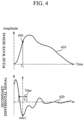
- FIG. 4 is a diagram explaining an example of determining a reference point
- FIG. 5 is a diagram explaining another example of determining a reference point.
- a cardiovascular information estimating apparatus 200 includes a pulse wave signal obtainer 210 and a processor 220.
- the processor 220 may include one or more processors, a memory, or a combination thereof.
- the pulse wave signal obtainer 210 may obtain a pulse wave signal of an object.
- the pulse wave signal may be a PPG signal.
- the pulse wave signal obtainer 210 may receive the pulse wave signal of the object from an external device which measures and/or stores pulse wave signals.
- the pulse wave signal obtainer 210 may communicate with the external device by using various communication techniques such as Bluetooth communication, Bluetooth Low Energy (BLE) communication, Near Field Communication (NFC), WLAN communication, Zigbee communication, Infrared Data Association (IrDA) communication, Wi-Fi Direct (WFD) communication, Ultra Wideband (UWB) communication, Ant+ communication, WIFI communication, Radio Frequency Identification (RFID) communication, and the like.
- BLE Bluetooth Low Energy
- NFC Near Field Communication
- WLAN Zigbee communication
- IrDA Infrared Data Association
- WFD Wi-Fi Direct
- UWB Ultra Wideband
- Ant+ communication Zigbee communication
- WIFI communication Radio Frequency Identification
- the pulse wave signal obtainer 210 may emit light of a predetermined wavelength onto the object, and may measure the pulse wave signal by receiving light reflected or scattered from the object.
- the pulse wave signal obtainer 210 may be implemented by a PPG sensor. As illustrated in FIG. 2 , the pulse wave signal obtainer 210 may include a light source 310 and a photodetector 320.
- the light source 310 may emit visible rays or near-infrared rays onto the object. However, wavelengths of light to be emitted by the light source 310 may vary according to a purpose of measurement. Further, the light source 310 is not necessarily a single light-emitting body, and may be formed as an array of a plurality of light-emitting bodies.
- the light source 310 may include a light emitting diode (LED), a laser diode, a fluorescent body, and the like.
- the photodetector 320 may measure a pulse wave signal by receiving light reflected or scattered from the object.
- the photodetector 320 may include a photo diode, a photo transistor (PTr), a charge-coupled device (CCD), and the like.
- the photodetector 320 is not necessarily a single device, and may be formed as an array of a plurality of devices.
- the light source and the photodetector may vary according to a purpose of measurement and the size and shape of the electronic device in which the pulse wave signal obtainer 210 is mounted, and the like.
- the processor 220 may control the overall operation of the cardiovascular information estimation apparatus 200.
- the processor 220 may control the pulse wave signal obtainer 210 to receive the pulse wave signal of the object.
- the processor 220 may remove noise from the obtained pulse wave signal.
- the processor 220 may remove noise from the pulse wave signal by using various filtering techniques such as a band pass filter, a moving average, and the like.
- the processor 220 may determine a reference point on the pulse wave signal.
- the reference point may be a point of reference for determining an area to be used as a cardiovascular feature value.
- the processor 220 may determine a time of a maximum point of the propagation wave component 110 included in the pulse wave signal 410, and may determine a point of the pulse wave signal, 410 which corresponds to the time of the maximum point of the propagation wave component 110, as the reference point. For example, referring to FIG. 4 , the processor 220 may determine a secondary differential signal 420 of a pulse wave signal 410, and may determine a local minimum point mini in a predetermined interval Tdur of the secondary differential signal 420. Further, the processor 220 may determine a time T1 of the determined local minimum point mini to be the time of the maximum point of the propagation wave component, and may determine a point 430 of the pulse wave signal 410 at the time T1, as the reference point. In this case, the predetermined interval Tdur may be an interval in which the propagation wave component 110 included in the pulse wave signal 410 may appear, and may be obtained experimentally as a preset value.
- the processor 220 may detect a pulse wave start point or a maximum ascending slope point from the pulse wave signal.
- the processor 220 may determine, as the reference point, one of the following: a point after a first duration (e.g., predetermined duration Ldur1 illustrated in FIG. 5 ) from the pulse wave start point, the maximum ascending slope point, and a point before/after a second duration (e.g., a predetermined duration Ldur2 illustrated in FIG. 5 ) from the maximum ascending slope point.
- a first duration and the second duration may be predetermined according to specifications of the cardiovascular information estimating apparatus 200.
- the processor 220 may detect pulse wave start points 510 and 530 or the maximum ascending slope point 520 from the pulse wave signal 410.
- the pulse wave start point 510 may be a minimum point of the pulse wave signal 410.
- the pulse wave start point 530 may indicate an intersection point between a tangent line at the maximum ascending slope point 520 of the pulse wave signal 410 and a height of the minimum point 510 of the pulse wave signal 410.
- the processor 220 may detect, as the pulse wave start point, the minimum point 510 of the pulse wave signal 410, or the intersection point 530 between the tangent line at the maximum ascending slope point 520 of the pulse wave signal 410 and the height of the minimum point 510 of the pulse wave signal 410.
- the processor 220 may determine, as the reference point, one of the following: a point 540 after a predetermined duration Ldur1 from the pulse wave start point 510; a point 550 after a predetermined duration Ldur2 from the pulse wave start point 530, the maximum ascending slope point 520, and points 560 and 570 before/after a predetermined duration Ldur3 from the maximum ascending slope point 520.
- the processor 220 may normalize the pulse wave signal 410.
- the processor 220 may normalize the pulse wave signal 410 based on at least one of the following: a pulse wave signal amplitude corresponding to the time of the maximum point of the propagation wave component 110 included in the pulse wave signal 410; a pulse wave signal amplitude at a point after a third duration from the pulse wave start point; a pulse wave signal amplitude at the maximum ascending slope point 520; a pulse wave signal amplitude at a point before/after a fourth duration from the maximum ascending slope point 520; and a duration of the pulse wave signal 410 at a point higher than the reference point.
- the third duration and the fourth duration may be predetermined according to specifications of the cardiovascular information estimating apparatus 200, and may be the same as or different from the aforementioned first duration and second duration, respectively.
- the processor 220 may determine an area of the pulse wave signal 410 which is at the point higher than the reference point on the normalized pulse wave signal, and may estimate cardiovascular information by using the determined area as a cardiovascular feature value.
- the cardiovascular information may include blood pressure, vascular age, arterial stiffness, vascular compliance, blood glucose, blood triglyceride, total peripheral resistance, and the like.
- the processor 220 may use a cardiovascular information estimation model which defines a relationship between a cardiovascular feature value and cardiovascular information.
- the processor 220 may remove an area of the propagation wave component 110, included in the area of the pulse wave signal 410 at the point higher than the reference point, from the area of the pulse wave signal 410, and may estimate cardiovascular information by using the area, from which an effect of the propagation wave component is removed, as a cardiovascular feature value. For example, the processor 220 may determine a time of the maximum point of the propagation wave component included in the pulse wave signal 410, and may determine a point of the pulse wave signal 410 which corresponds to the time.
- the processor 220 may determine an area of the propagation wave component 110 based on the determined point of the pulse wave signal 410 and the reference point; and may remove the area of the propagation wave component 110 from the area of the pulse wave signal 410 which is at the point higher than the reference point.
- the processor 220 may improve the accuracy of a blood pressure estimation since the blood pressure estimation is performed based on the area under the curve of the pulse wave signal 410 which is robust against changes in the maximum amplitude of the pulse wave signal 410 and a width of the pulse wave signal above a reference amplitude line (or the reference point).
- the processor 220 may also calculate an area of the pulse wave signal 410 which is at the point higher than a reference point on the normalized pulse wave signal; and upon calculating the area of the pulse wave signal 410 which is at the point higher than the reference point, the processor 220 may also normalize the calculated area.
- FIG. 6 is a diagram explaining an example of a cardiovascular feature value.
- a reference numeral 610 denotes a reference point
- a reference numeral 620 denotes a point corresponding to a maximum point of a propagation wave component 110
- a reference numeral 630 denotes a normalization point for normalizing the pulse wave signal 410.
- the cardiovascular feature value may include values such as A0/Pn, A0/(Pn* Peak_dur), (A0-A1)/Pn, (A0-A1)/(Pn ⁇ Peak_dur), and the like.
- A0 denotes an area under the pulse wave signal 410 which is at a point higher than the reference point 610
- Pn denotes an amplitude of the normalization point 630 used for normalization
- Peak_dur denotes a duration of the pulse wave signal 410 at a point higher than the reference point 610 and a duration of the area determined as A0
- A1 denotes an area of the propagation wave component 110 included in the A0
- A2 denotes an area under the pulse wave signal 410 and above the maximum point 620 of the propagation wave component 110.
- the points 610, 620, and 630 may be the same as or different from each other.
- the processor 220 may perform a blood pressure estimation based on at least one of A0/Pn, A0/(Pn ⁇ Peak_dur), (A0-A1)/Pn, (A0-A1)/(Pn ⁇ Peak_dur), and A2.
- FIG. 7 is a diagram illustrating an apparatus for estimating cardiovascular information according to another example embodiment.
- the cardiovascular information estimating apparatus 700 includes the pulse wave signal obtainer 210, the processor 220, an input interface 710, a memory 720, a communication interface730, and an output interface 740.
- the pulse wave signal obtainer 210 and the processor 220 are described above with reference to FIGS. 2 to 6 , such that detailed description thereof will be omitted.
- the input interface 710 may receive input of various operation signals from a user.
- the input interface 710 may include a keypad, a dome switch, a touch pad (static pressure/capacitance), a jog wheel, a jog switch, a hardware (H/W) button, and the like.
- the touch pad which forms a layer structure with a display, may be called a touch screen.
- the memory 720 may store programs or commands for operation of the cardiovascular information estimating apparatus 700, and may store data input to and output from the cardiovascular information estimating apparatus 700. Further, the memory 720 may store the obtained pulse wave signal, the cardiovascular information estimation model, and the like.
- the memory 720 may include at least one storage medium of a flash memory type memory, a hard disk type memory, a multimedia card micro type memory, a card type memory (e.g., an SD memory, an XD memory, etc.), a Random Access Memory (RAM), a Static Random Access Memory (SRAM), a Read Only Memory (ROM), an Electrically Erasable Programmable Read Only Memory (EEPROM), a Programmable Read Only Memory (PROM), a magnetic memory, a magnetic disk, and an optical disk, and the like.
- the cardiovascular information estimating apparatus 700 may operate an external storage medium, such as web storage and the like, which performs a storage function of the memory 720 on the Internet.
- the communication interface730 may perform communication with an external device.
- the communication interface730 may transmit, to the external device, the data input to the cardiovascular information estimating apparatus 700, data stored in and processed by the cardiovascular information estimating apparatus 700, and the like, or may receive, from the external device, various data useful for estimating cardiovascular information.
- the external device may be medical equipment using the data input to the cardiovascular information estimating apparatus 700, the data stored in and processed by the cardiovascular information estimating apparatus 700, and the like, a printer to print out results, or a display to display the results.
- the external device may be a digital TV, a desktop computer, a cellular phone, a smartphone, a tablet PC, a laptop computer, a personal digital assistant (PDA), a portable multimedia player (PMP), a navigation, an MP3 player, a digital camera, a wearable device, and the like, but is not limited thereto.
- the communication interface730 may communicate with an external device by using Bluetooth communication, Bluetooth Low Energy (BLE) communication, Near Field Communication (NFC), WLAN communication, Zigbee communication, Infrared Data Association (IrDA) communication, Wi-Fi Direct (WFD) communication, Ultra-Wideband (UWB) communication, Ant+ communication, WIFI communication, Radio Frequency Identification (RFID) communication, 3G communication, 4G communication, 5G communication, and the like.
- BLE Bluetooth Low Energy
- NFC Near Field Communication
- WLAN Zigbee communication
- IrDA Infrared Data Association
- Wi-Fi Direct (WFD) communication Wi-Fi Direct
- UWB Ultra-Wideband
- Ant+ communication WIFI communication
- RFID Radio Frequency Identification
- the output interface 740 may output the data input to the cardiovascular information estimating apparatus 700, the data stored in and processed by the cardiovascular information estimating apparatus 700, and the like.
- the output interface 740 may output the data input to the cardiovascular information estimating apparatus 700, the data stored in and processed by the cardiovascular information estimating apparatus 700, and the like, by using at least one of an acoustic method, a visual method, and a tactile method.
- the output interface 740 may include a display, a speaker, a vibrator, and the like.
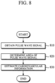
- FIG. 8 is a diagram illustrating a method of estimating cardiovascular information according to an example embodiment according to an example embodiment.
- the cardiovascular information estimating method of FIG. 8 may be performed by the cardiovascular information estimating apparatus 200 or 700 of FIG. 2 or 7 .
- the cardiovascular information estimating apparatus 200 or 700 may obtain a pulse wave signal 410 of an object in operation 810.
- the pulse wave signal 410 may be a PPG signal.
- the cardiovascular information estimating apparatus 200 or 700 may obtain the pulse wave signal 410 of the object by receiving the pulse wave signal 410 from an external device which measures and/or stores pulse wave signals, or may obtain the pulse wave signal 410 by emitting light of a predetermined wavelength and receiving light reflected or scattered from the object.
- the cardiovascular information estimating apparatus 200 or 700 may determine an area of the pulse wave signal 410 which is at a point higher than a reference point on the pulse wave signal in operation 820.
- the reference point may be a point of reference for determining an area to be used as a cardiovascular feature value.
- the cardiovascular information estimating apparatus 200 or 700 may estimate cardiovascular information of the object based on the determined area of the pulse wave signal 410 in operation 830.
- the cardiovascular information estimating apparatus 200 or 700 may use the determined area of the pulse wave signal 410 as the cardiovascular feature value, and may estimate cardiovascular information of the object by using a cardiovascular information estimation model which defines a relationship between the cardiovascular feature value and cardiovascular information.
- the cardiovascular information may include blood pressure, vascular age, arterial stiffness, vascular compliance, blood glucose, blood triglyceride, total peripheral resistance, and the like.
- the cardiovascular information estimating apparatus 200 or 700 may remove an area of the propagation wave component 110, included in the area of the pulse wave signal 410 at the point higher than the reference point, from the area of the pulse wave signal 410, and may estimate cardiovascular information by using the area, from which an effect of the propagation wave component 110 is removed, as a cardiovascular feature value.
- the cardiovascular information estimating apparatus 200 or 700 may determine a time of a maximum point of the propagation wave component included in the pulse wave signal 410, and may determine a point of the pulse wave signal 410 which corresponds to the time.
- the cardiovascular information estimating apparatus 200 or 700 may determine an area of the propagation wave component 110 based on the determined point of the pulse wave signal 410 and the reference point; and may remove the area of the propagation wave component 110 from the area of the pulse wave signal which is at the point higher than the reference point.
- FIG. 9 is a diagram illustrating a method of determining an area of a pulse wave signal which is at a point higher than a reference point according to an example embodiment.
- the method of FIG. 9 may be an example of the determining of an area of a pulse wave signal 410 which is at a point higher than a reference point in operation 820 of FIG. 8 .
- the cardiovascular information estimating apparatus 200 or 700 may determine a reference point on a pulse wave signal in operation 910.
- the cardiovascular information estimating apparatus 200 or 700 may determine a time of a maximum point of a propagation wave component 110 included in the pulse wave signal 410, and may determine a point of the pulse wave signal 410, which corresponds to the time, as the reference point. For example, the cardiovascular information estimating apparatus 200 or 700 may determine a secondary differential signal of the pulse wave signal 410, and may determine a local minimum point in a predetermined interval of the secondary differential signal. Further, the cardiovascular information estimating apparatus 200 or 700 may determine a time of the determined local minimum point to be the time of the maximum point of the propagation wave component 110, and may determine a point of the pulse wave signal, which corresponds to the time, as the reference point.
- the cardiovascular information estimating apparatus 200 or 700 may detect a pulse wave start point or a maximum ascending slope point from the pulse wave signal 410; and may determine, as the reference point, one of the following: a point after a first duration from the pulse wave start point, the maximum ascending slope point, and a point before/after a second duration from the maximum ascending slope point.
- the cardiovascular information estimating apparatus 200 or 700 may detect, as the pulse wave start point, a minimum point of the pulse wave signal 410, or an intersection point between a tangent line at the maximum ascending slope point of the pulse wave signal 410 and a height of the minimum point of the pulse wave signal 410.
- the cardiovascular information estimating apparatus 200 or 700 may normalize the pulse wave signal 410 in operation 920.
- the cardiovascular information estimating apparatus 200 or 700 may normalize the pulse wave signal 410 based on at least one of the following: a pulse wave signal amplitude corresponding to the time of the maximum point of the propagation wave component 110 included in the pulse wave signal 410; a pulse wave signal amplitude at a point after a third duration from the pulse wave start point; a pulse wave signal amplitude at the maximum ascending slope point; a pulse wave signal amplitude at a point before/after a fourth duration from the maximum ascending slope point; and a duration of the pulse wave signal 410 at a point higher than the reference point.
- the cardiovascular information estimating apparatus 200 or 700 may determine an area of the pulse wave signal which is at the point higher than the reference point on the normalized pulse wave signal in operation 930.
- FIG. 10 is a diagram illustrating a method of determining an area of a pulse wave signal which is at a point higher than a reference point according to another example embodiment.
- the method of FIG. 10 may be another example of the determining of an area of a pulse wave signal 410 which is at a point higher than a reference point in operation 820 of FIG. 8 .
- the cardiovascular information estimating apparatus 200 or 700 may determine a reference point on a pulse wave signal 410 in operation 1010.
- the cardiovascular information estimating apparatus 200 or 700 may determine an area under the pulse wave signal 410 which is at a point higher than the reference point on the pulse wave signal 410 in operation 1020.
- the cardiovascular information estimating apparatus 200 or 700 may normalize the pulse wave signal 410 in operation 1030.
- the cardiovascular information estimating apparatus 200 or 700 may normalize the pulse wave signal 410 based on at least one of the following: a pulse wave signal amplitude corresponding to the time of the maximum point of the propagation wave component 110 included in the pulse wave signal 410; a pulse wave signal amplitude at a point after a third duration from the pulse wave start point; a pulse wave signal amplitude at the maximum ascending slope point; a pulse wave signal amplitude at a point before/after a fourth duration from the maximum ascending slope point; and a duration of the pulse wave signal at a point higher than the reference point.
- FIG. 11 is a diagram illustrating a method of estimating cardiovascular information according to another example embodiment.
- the cardiovascular information estimating method of FIG. 11 may be performed by the cardiovascular information estimating apparatus 200 or 700 of FIG. 2 or 7 .
- the operations 810, 820, and 830 of FIG. 11 are described above with reference to FIG. 8 , such that detailed description thereof will be omitted.
- the cardiovascular information estimating apparatus 200 or 700 may remove noise from the obtained pulse wave signal in operation 815.
- the cardiovascular information estimating apparatus 200 or 700 may remove noise from the pulse wave signal 410 by using various filtering techniques such as a band pass filter, a moving average, and the like.
- FIG. 12 is a diagram illustrating an apparatus for estimating cardiovascular information according to another example embodiment
- FIG. 13 is a diagram explaining a first feature and a second feature extracted in a first operation mode
- FIG. 14 is a diagram explaining a method of obtaining P n (P 1 , P 2 , P 3 ) and T n (T 1 , T 2 , T 3 ) of FIG. 13
- FIG. 15 is a diagram explaining a method of obtaining P max and T max of FIG. 13 .
- a cardiovascular information estimating apparatus 1200 includes the pulse wave signal obtainer 210 and a processor 1210.
- the processor 1210 may include one or more processors, a memory, or a combination thereof.
- the pulse wave signal obtainer 210 is described above with reference to FIGS. 2 and 3 , such that detailed description thereof will be omitted.
- the processor 1210 may control the overall operation of the cardiovascular information estimation apparatus 1200.
- the processor 1210 may control the pulse wave signal obtainer 210 to receive a pulse wave signal 1300 of an object.
- the processor 1210 may remove noise from the obtained pulse wave signal 1300.
- the processor 1210 may remove noise from the pulse wave signal 1300 by using various filtering techniques such as a band pass filter, a moving average, and the like.
- the processor 1210 may determine a secondary differential signal 1400 of the pulse wave signal 1300; and if there is a local minimum point in a predetermined interval of the second differential signal 1400, the processor 1210 may estimate cardiovascular information in a first operation mode, and if there is no local minimum point in the predetermined interval of the second differential signal 1400, the processor 1210 may estimate cardiovascular information in a second operation mode.
- the predetermined interval may be an interval in which the propagation wave component included in the pulse wave signal 1300 may appear, and may be obtained experimentally as a preset value.
- the processor 1210 may extract a first feature value and/or a second feature value from the pulse wave signal 1300.
- the first feature value may be associated with cardiac output
- the second feature value may be associated with total peripheral resistance.
- the processor 1210 may determine a time of a maximum point of a propagation wave component and a time of a maximum point of a reflection wave component by analyzing a secondary differential signal 1400 of the pulse wave signal 1300; and may determine a pulse wave signal amplitude corresponding to each time of the maximum points of the propagation wave component and the reflection wave component.
- the processor 1210 may extract the first feature value and/or the second feature value by combining the time of the maximum point of the propagation wave component, the pulse wave signal amplitude corresponding to the time of the maximum point of the propagation wave component, the time of the maximum point of the reflection wave component, the pulse wave signal amplitude corresponding to the time of the maximum point of the reflection wave component, and the like.
- a pulse wave signal 1300 may be formed by a superposition of three component pulses 1310 to 1330.
- a reference numeral 1300 denotes a pulse wave signal
- a reference numeral 1310 denotes a first component pulse (propagation wave component)
- a reference numeral 1320 denotes a second component pulse (a first reflection wave component)
- a reference numeral 1330 denotes a third component pulse (a second reflection wave component).
- ⁇ dur denotes a system
- the first feature is a feature associated with cardiac output, and may include, for example, values obtained by P max /P area , P max /P 3 , P sys /P 3 , P 1 /P 3 , P 2 /P 3 , P 2 /P 1 , and the like.
- the second feature is a feature associated with total peripheral resistance, and may include, for example, values obtained by 1/(T 3 -T sys ), 1/(T 3 -T max ), 1/(T 3 -T 1 ), 1/(T 3 -T 2 ), P 3 /P 1 , P 2 /P 1 , and the like.
- T sys denotes the time of the middle point between T 1 and T max in FIG. 3
- T sys is not limited thereto. That is, T sys may be an internally dividing point between T 1 and T max , and an internally dividing point between T 1 and T 2 .
- P n (P 1 , P 2 , P 3 ) and T n (T 1 , T 2 , T 3 ) of FIG. 13 may be obtained based on the secondary differential signal 1400 of the pulse wave signal 1300.
- the secondary differential signal 1400 may include a plurality of local minimum points min1 to min3. By arranging the local minimum points min1 to min3, included in the secondary differential signal 1400, in time-sequential order, the first local minimum point min1 corresponds to T 1 , the second local minimum point min2 corresponds to T 2 , and the third local minimum point min3 corresponds to T 3 .
- P max and T max of FIG. 13 may be obtained based on the secondary differential signal 1400 of the pulse wave signal 1300.
- the secondary differential signal 1400 may include a plurality of local maximum points max1 to max3.
- a search area for P max i.e., a first interval
- the processor 1210 may search for P max in the search area.
- a time of a maximum point of the pulse wave signal 1300 corresponds to T max
- an amplitude of the pulse wave signal 1300 at T max corresponds to P max .
- the processor 1210 may estimate cardiovascular information by using the extracted first feature value and/or second feature value as the cardiovascular feature value.
- the processor 1210 may use a cardiovascular information estimation model which defines a relationship between the cardiovascular feature value and cardiovascular information.
- the processor 1210 may determine a reference point on the pulse wave signal 1300 in the second operation mode.
- the processor 1210 may detect a pulse wave start point or a maximum ascending slope point from the pulse wave signal 1300; and may determine, as the reference point, one of the following: a point after a first duration from the pulse wave start point, the maximum ascending slope point, and a point before/after a second duration from the maximum ascending slope point.
- the processor 1210 may detect pulse wave start points 410 and 430 or a maximum ascending slope point 420.
- the pulse wave start point 410 may indicate a minimum point of the pulse wave signal 1300
- the pulse wave start point 430 may indicate an intersection point 430 between a tangent line at the maximum ascending slope point 420 of the pulse wave signal 1300and a height of the minimum point 410 of the pulse wave signal 1300. That is, the processor 1210 may detect, as the pulse wave start point, the minimum point 410 of the pulse wave signal, or the intersection point 430 between the tangent line at the maximum ascending slope point 420 of the pulse wave signal and the height of the minimum point 410 of the pulse wave signal.
- the processor 1210 may determine, as the reference point, one of the following: a point 440 after a predetermined duration Ldur1 from the pulse wave start point 410, a point 450 after a predetermined duration Ldur2 from the pulse wave start point 430, the maximum ascending slope point 420, and points 460 and 470 before/after a predetermined duration Ldur3 from the maximum ascending slope point 420.
- the processor 1210 may normalize the pulse wave signal. In one embodiment, the processor 1210 may normalize the pulse wave signal based on at least one of the following: a pulse wave signal amplitude at a point after a third duration from the pulse wave start point; a pulse wave signal amplitude at the maximum ascending slope point; a pulse wave signal amplitude at a point before/after a fourth duration from the maximum ascending slope point; and a duration of the pulse wave signal at a point higher than the reference point.
- the processor 1210 may determine an area of the pulse wave signal which is at the point higher than the reference point on the normalized pulse wave signal, and may estimate cardiovascular information by using the determined area as a cardiovascular feature value. In one embodiment, the processor 1210 may use a cardiovascular information model which defines a relationship between the cardiovascular feature value and cardiovascular information.
- the processor 1210 may remove an area of the propagation wave component, included in the area of the pulse wave signal at the point higher than the reference point, from the area of the pulse wave signal, and may estimate cardiovascular information by using the area, from which an effect of the propagation wave component is removed, as a cardiovascular feature value.
- the processor 1210 may determine an area of the propagation wave component based on the determined point of the pulse wave signal and the reference point; and may remove the area of the propagation wave component from the area of the pulse wave signal which is higher than the reference point.
- the predetermined point may be a point at which the propagation wave component included in the pulse wave signal may appear, and may be obtained experimentally as a preset value.
- the processor 1210 may also calculate the area of the pulse wave signal which is at the point higher than the reference point on the normalized pulse wave signal; and upon calculating the area of the pulse wave signal which is at the point higher than the reference point, the processor 1210 may also normalize the calculated area.
- FIG. 16 is a diagram illustrating a method of estimating cardiovascular information according to another example embodiment.
- the cardiovascular information estimating method of FIG. 16 may be performed by the cardiovascular information estimating apparatus 1200 of FIG. 12 .
- the cardiovascular information estimating apparatus 1200 may obtain a pulse wave signal of an object in operation 1610.
- the pulse wave signal may be a PPG signal.
- the cardiovascular information estimating apparatus 1200 may obtain the pulse wave signal of the object by receiving the pulse wave signal from an external device which measures and/or stores pulse wave signals, or may obtain the pulse wave signal by emitting light of a predetermined wavelength and receiving light reflected or scattered from the object.
- the cardiovascular information estimating apparatus 1200 may determine a secondary differential signal of the pulse wave signal in operation 1620, and may determine whether there is a local minimum point in a predetermined interval of the secondary differential signal in operation 1630.
- the predetermined interval may be an interval in which the propagation wave component included in the pulse wave signal may appear, and may be obtained experimentally as a preset value.
- the cardiovascular information estimating apparatus 1200 may estimate cardiovascular information of the object in the first operation mode in operation 1640.
- the cardiovascular information estimating apparatus 1200 may estimate cardiovascular information of the object in the second operation mode in operation 1650.
- FIG. 17 is a diagram illustrating a method of estimating cardiovascular information in a first operation mode according to an example embodiment.
- the method of FIG. 17 may be an example of the estimating of cardiovascular information in the first operation mode in operation 1640 of FIG. 16 .
- the cardiovascular information estimating apparatus 1200 may extract at least one feature value from a pulse wave signal in operation 1710.
- the feature value may include a first feature value and a second feature value, in which the first feature value may be associated with cardiac output, and the second feature value may be associated with total peripheral resistance.
- the cardiovascular information estimating apparatus 1200 may analyze a secondary differential signal of the pulse wave signal to determine a time of a maximum point of a propagation wave component and a time of a maximum point of a reflection wave component; and may determine a pulse wave signal amplitude corresponding to each time of the maximum points of the propagation wave component and the reflection wave component.
- the cardiovascular information estimating apparatus 1200 may extract at least one feature value by combining the time of the maximum point of the propagation wave component, the pulse wave signal amplitude corresponding to the time of the maximum point of the propagation wave component, the time of the maximum point of the reflection wave component, the pulse wave signal amplitude corresponding to the time of the maximum point of the reflection wave component, and the like.
- the first feature value and the second feature value are described above in detail with reference to FIGS. 13 to 15 , such that detailed description thereof will be omitted.
- the cardiovascular information estimating apparatus 1200 may estimate cardiovascular information by using the extracted at least one feature value as a cardiovascular feature value in operation 1720.
- the cardiovascular information estimating apparatus 1200 may use a cardiovascular information estimation model which defines a relationship between the cardiovascular feature value and cardiovascular information.
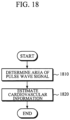
- FIG. 18 is a diagram illustrating a method of estimating cardiovascular information in a second operation mode according to an example embodiment.
- the method of FIG. 18 may be an example of the estimating of cardiovascular information in the second operation mode in operation 1650 of FIG. 16 .
- the cardiovascular information estimating apparatus 1200 may determine an area of a pulse wave signal which is at a point higher than a reference point in operation 1810.
- the reference point may be a point of reference for determining an area to be used as a cardiovascular feature value.
- the cardiovascular information estimating apparatus 1200 may determine the reference point on the pulse wave signal, may normalize the pulse wave signal, and then may determine the area of the pulse wave signal which is at the point higher than the reference point on the normalized pulse wave signal.
- the cardiovascular information estimating apparatus 1200 may detect a pulse wave pulse wave start point or a maximum ascending slope point from the pulse wave signal; and may determine, as the reference point, one of the following: a point after a first duration from the pulse wave start point, the maximum ascending slope point, and a point before/after a second duration from the maximum ascending slope point.
- the pulse wave start point may indicate a minimum point of the pulse wave signal, or an intersection point between a tangent line at the maximum ascending slope point of the pulse wave signal and a height of the minimum point of the pulse wave signal.
- the cardiovascular information estimating apparatus 1200 may normalize the pulse wave signal based on at least one of the following: a pulse wave signal amplitude at a point after a third duration from the pulse wave start point; a pulse wave signal amplitude at the maximum ascending slope point; a pulse wave signal amplitude at a point before/after a fourth duration from the maximum ascending slope point; and a duration of the pulse wave signal at the point higher than the reference point.
- the cardiovascular information estimating apparatus 1200 may determine an area of the pulse wave signal which is at the point higher than the reference point on the normalized pulse wave signal.
- the cardiovascular information estimating apparatus 1200 may estimate cardiovascular information by using the determined area of the pulse wave signal, which is at the point higher than the reference point, as a cardiovascular feature value in operation 1820.
- the cardiovascular information estimating apparatus 1200 may use a cardiovascular information model which defines a relationship between the cardiovascular feature value and cardiovascular information.
- the cardiovascular information estimating apparatus 1200 may remove an area of the propagation wave component, included in the area of the pulse wave signal at the point higher than the reference point, from the area of the pulse wave signal, and may estimate cardiovascular information by using the area, from which an effect of the propagation wave component is removed, as a cardiovascular feature value.
- the cardiovascular information estimating apparatus 1200 may determine an area of the propagation wave component based on the determined point of the pulse wave signal and the reference point; and may remove the area of the propagation wave component from the area of the pulse wave signal which is at the point higher than the reference point.
- the predetermined point may be a point at which the propagation wave component included in the pulse wave signal may appear, and may be obtained experimentally as a preset value.
- the cardiovascular information estimating apparatus 1200 may also calculate the area of the pulse wave signal which is at the point higher than the reference point on the normalized pulse wave signal; and upon calculating the area of the pulse wave signal which is at the point higher than the reference point, the cardiovascular information estimating apparatus 1200 may also normalize the calculated area.
- an example embodiment can be embodied as computer-readable code on a computer-readable recording medium.
- the computer-readable recording medium is any data storage device that can store data that can be thereafter read by a computer system. Examples of the computer-readable recording medium include read-only memory (ROM), random-access memory (RAM), CD-ROMs, magnetic tapes, floppy disks, and optical data storage devices.
- the computer-readable recording medium can also be distributed over network-coupled computer systems so that the computer-readable code is stored and executed in a distributed fashion.
- an example embodiment may be written as a computer program transmitted over a computer-readable transmission medium, such as a carrier wave, and received and implemented in general-use or special-purpose digital computers that execute the programs.
- one or more units of the above-described apparatuses and devices can include circuitry, a processor, a microprocessor, etc., and may execute a computer program stored in a computer-readable medium.
Claims (15)
- Appareil (200) d'estimation d'informations cardiovasculaires, l'appareil comprenant :une mémoire (720) stockant des instructions ; etun processeur (220) configuré pour exécuter les instructions afin :d'obtenir (810) un signal d'onde pulsée (100; 410) d'un sujet, le signal d'onde pulsée étant formé par la superposition d'une composante d'onde de propagation et d'une pluralité de composantes d'onde de réflexion ;de déterminer (820) une zone située sous le signal d'onde pulsée et au-dessus d'un point de référence (610) sur le signal d'onde pulsée ;de déterminer (1620) un signal différentiel secondaire (420) du signal d'onde d'impulsion ;d'analyser le signal différentiel secondaire pour :déterminer un point minimum local dans un intervalle prédéterminé du signal différentiel secondaire, etdéterminer l'heure du point minimum local comme étant l'heure du point maximum de la composante de l'onde de propagation ;de déterminer (1630) un point du signal d'onde d'impulsion qui correspond à l'instant du point minimum local ;de déterminer une zone de la composante d'onde de propagation incluse dans la zone déterminée du signal d'onde d'impulsion sur la base du point déterminé du signal d'onde d'impulsion et du point de référence ;de retirer la zone déterminée de la composante d'onde de propagation de la zone déterminée du signal d'onde d'impulsion ; etd'estimer (830) les informations cardiovasculaires du sujet sur la base de la zone déterminée du signal d'onde d'impulsion dont la zone déterminée de la composante d'onde de propagation est retirée.
- Appareil selon la revendication 1, comprenant en outre un dispositif d'obtention d'un signal d'onde d'impulsion comprenant :une source de lumière (310) configurée pour émettre de la lumière sur le sujet; etun photodétecteur (320) configuré pour obtenir le signal d'onde d'impulsion en recevant la lumière renvoyée par le sujet,dans lequel le dispositif d'obtention du signal d'onde d'impulsion (210) est configuré pour fournir le signal d'onde d'impulsion au processeur.
- Appareil selon les revendications 1 ou 2, dans lequel
le point déterminé du signal d'onde d'impulsion est le point de référence. - Appareil selon l'une des revendications 1 à 3, dans lequel le processeur est en outre configuré pour exécuter les instructions afin
de détecter un point de départ de l'onde d'impulsion ou un point de pente ascendante maximale (520) à partir du signal d'onde d'impulsion, et de déterminer, en tant que point de référence, l'un des points suivants : un point après une première durée à partir du point de départ de l'onde d'impulsion, le point de pente ascendante maximale, et un point avant ou après une deuxième durée à partir du point de pente ascendante maximale. - Appareil selon la revendication 4, dans lequel le processeur est en outre configuré pour exécuter les instructions afin de détecter, en tant que point de départ de l'onde d'impulsion, un point minimum (510) du signal d'onde d'impulsion, ou un point d'intersection (530) entre une ligne tangente au point de pente ascendante maximale du signal d'onde d'impulsion et une hauteur du point minimum du signal d'onde d'impulsion.
- Appareil selon l'une des revendications 1 à 5, dans lequel le processeur est en outre configuré pour exécuter les instructions afin de normaliser (920) le signal d'onde d'impulsion ou la zone déterminée du signal d'onde d'impulsion sur la base d'au moins l'un des éléments suivants une amplitude de signal d'onde d'impulsion correspondant à un moment d'un point maximum d'une composante d'onde de propagation incluse dans le signal d'onde d'impulsion, une amplitude du signal d'onde d'impulsion à un point situé après une troisième durée à partir d'un point de départ de l'onde d'impulsion, une amplitude du signal d'onde d'impulsion à un point de pente ascendante maximale, une amplitude du signal d'onde d'impulsion à un point situé avant ou après une quatrième durée à partir du point de pente ascendante maximale, et une durée du signal d'onde d'impulsion à un point plus élevé que le point de référence, ou
dans lequel les informations cardiovasculaires comprennent au moins l'un des éléments suivants : pression artérielle, âge vasculaire, rigidité artérielle, compliance vasculaire, glucose sanguin, triglycérides sanguins et résistance périphérique totale. - Appareil selon l'une des revendications 1 à 6, dans lequel le processeur est en outre configuré pour exécuter les instructions afin d'estimer les informations cardiovasculaires en utilisant la zone déterminée du signal d'onde d'impulsion à partir de laquelle la zone de la composante d'onde de propagation est supprimée comme valeur de caractéristique cardiovasculaire.
- Appareil selon la revendication 7, dans lequel le processeur est en outre configuré pour exécuter les instructions afin d'estimer les informations cardiovasculaires à l'aide d'un modèle d'estimation des informations cardiovasculaires qui définit une relation entre la valeur de la caractéristique cardiovasculaire et les informations cardiovasculaires.
- Appareil selon l'une des revendications 1 à 8, dans lequel le processeur est en outre configuré pour exécuter les instructions afin d'éliminer (815) le bruit du signal d'onde d'impulsion obtenu.
- Procédé d'estimation d'informations cardiovasculaires, comprenant les opérations suivantes :obtenir (1620) un signal d'onde pulsée d'un sujet, le signal d'onde pulsée étant formé par la superposition d'une composante d'onde de propagation et d'une pluralité de composantes d'onde de réflexion ;déterminer (820) une zone située sous le signal d'onde de pouls et au-dessus d'un point de référence (610) sur le signal d'onde de pouls ;déterminer (1620) un signal différentiel secondaire du signal d'onde d'impulsion;analyser le signal différentiel secondaire pour :déterminer un point minimum local dans un intervalle prédéterminé du signal différentiel secondaire, etdéterminer l'heure du point minimum local comme étant l'heure du point maximum de la composante de l'onde de propagation ;déterminer (1630) un point du signal d'onde d'impulsion qui correspond à l'instant du point minimum local ;déterminer une zone de la composante d'onde de propagation incluse dans la zone déterminée du signal d'onde d'impulsion sur la base du point déterminé du signal d'onde d'impulsion et du point de référence ;retirer la zone déterminée de la composante d'onde de propagation de la zone déterminée du signal d'onde d'impulsion ; etestimer (830) des informations cardiovasculaires du sujet sur la base de la zone déterminée du signal d'onde d'impulsion dont la zone déterminée de la composante d'onde de propagation est supprimée.
- Procédé selon la revendication 10, dans lequel l'obtention du signal d'onde d'impulsion du sujet comprend l'émission de lumière sur le sujet ; et l'obtention du signal d'onde d'impulsion par la réception de la lumière revenant du sujet, ou
dans lequel l'estimation des informations cardiovasculaires comprend l'extraction d'au moins une valeur caractéristique par l'analyse du signal différentiel secondaire ; et l'estimation des informations cardiovasculaires par l'utilisation d'au moins une valeur caractéristique extraite en tant que valeur caractéristique cardiovasculaire. - Procédé selon la revendication 11, dans lequel l'extraction d'au moins une valeur de caractéristique comprend les opérations suivantes :déterminer un point maximum d'une composante de l'onde de réflexion en analysant le signal différentiel secondaire ;déterminer l'amplitude d'un signal d'onde d'impulsion correspondant au moment du point maximum de la composante d'onde de réflexion ; etextraire au moins une valeur caractéristique en combinant au moins l'un des éléments suivants : l'heure du point maximal de la composante onde de propagation, une amplitude de signal d'onde d'impulsion correspondant à l'heure du point maximal de la composante onde de propagation, l'heure du point maximal de la composante onde de réflexion, et une amplitude de signal d'onde d'impulsion correspondant à l'heure du point maximal de la composante onde de réflexion.
- Procédé selon la revendication 10, dans lequel la détermination de la zone du signal d'onde de pouls comprend les opérations suivantes :détecter un point de départ de l'onde d'impulsion ou d'un point de pente ascendante maximale à partir du signal d'onde d'impulsion ; etdéterminer, en tant que point de référence, l'un des points suivants : un point après une première durée à partir du point de départ de l'onde de pouls, le point de pente ascendante maximale, et un point avant ou après une deuxième durée à partir du point de pente ascendante maximale.
- Procédé selon la revendication 13, dans lequel la détection du point de départ de l'onde d'impulsion ou du point de pente ascendante maximale comprend la détection, en tant que point de départ de l'onde d'impulsion, d'un point minimum (510) du signal d'onde d'impulsion, ou d'un point d'intersection (530) entre une ligne tangente au point de pente ascendante maximale du signal d'onde d'impulsion et une hauteur du point minimum du signal d'onde d'impulsion.
- Procédé selon la revendication 10, dans lequel l'estimation des informations cardiovasculaires comprend la normalisation du signal d'onde de pouls ou de la zone déterminée du signal d'onde de pouls sur la base d'au moins un des éléments suivants : amplitude du signal d'onde de pouls au point après une première durée à partir d'un point de départ de l'onde de pouls, amplitude du signal d'onde de pouls à un point de pente ascendante maximale, amplitude du signal d'onde de pouls à un point avant ou après une deuxième durée à partir du point de pente ascendante maximale, et durée du signal d'onde de pouls à un point plus élevé que le point de référence.
Applications Claiming Priority (1)
| Application Number | Priority Date | Filing Date | Title |
|---|---|---|---|
| KR1020180167338A KR20200077932A (ko) | 2018-12-21 | 2018-12-21 | 심혈관 정보 추정 장치 및 방법 |
Publications (2)
| Publication Number | Publication Date |
|---|---|
| EP3669763A1 EP3669763A1 (fr) | 2020-06-24 |
| EP3669763B1 true EP3669763B1 (fr) | 2023-11-15 |
Family
ID=68916423
Family Applications (1)
| Application Number | Title | Priority Date | Filing Date |
|---|---|---|---|
| EP19216050.5A Active EP3669763B1 (fr) | 2018-12-21 | 2019-12-13 | Appareil et procédé d'estimation d'informations cardiovasculaires |
Country Status (4)
| Country | Link |
|---|---|
| US (1) | US20200196880A1 (fr) |
| EP (1) | EP3669763B1 (fr) |
| KR (2) | KR20200077932A (fr) |
| CN (1) | CN111345788A (fr) |
Families Citing this family (1)
| Publication number | Priority date | Publication date | Assignee | Title |
|---|---|---|---|---|
| KR102445629B1 (ko) * | 2021-07-28 | 2022-09-21 | 주식회사 클레스앤피 | 비침습 혈당측정 시스템 및 그 동작방법 |
Family Cites Families (6)
| Publication number | Priority date | Publication date | Assignee | Title |
|---|---|---|---|---|
| JP4120083B2 (ja) * | 1999-02-19 | 2008-07-16 | オムロンヘルスケア株式会社 | 非観血連続血圧推定装置および非観血連続血圧予測装置 |
| JP2000300526A (ja) * | 1999-04-23 | 2000-10-31 | Matsushita Electric Works Ltd | 血圧計 |
| US7544168B2 (en) * | 2004-09-30 | 2009-06-09 | Jerusalem College Of Technology | Measuring systolic blood pressure by photoplethysmography |
| CN101347334B (zh) * | 2007-07-19 | 2012-09-05 | 深圳迈瑞生物医疗电子股份有限公司 | 血氧饱和度测量方法和装置 |
| US8398556B2 (en) * | 2008-06-30 | 2013-03-19 | Covidien Lp | Systems and methods for non-invasive continuous blood pressure determination |
| IT201700031915A1 (it) * | 2017-03-23 | 2018-09-23 | Univ Degli Studi Di Modena E Reggio Emilia | Sistema e metodo per la rilevazione di parametri fisiologici vitali di un soggetto. |
-
2018
- 2018-12-21 KR KR1020180167338A patent/KR20200077932A/ko not_active Application Discontinuation
-
2019
- 2019-12-11 US US16/710,934 patent/US20200196880A1/en active Pending
- 2019-12-13 EP EP19216050.5A patent/EP3669763B1/fr active Active
- 2019-12-23 CN CN201911336061.4A patent/CN111345788A/zh active Pending
-
2023
- 2023-10-27 KR KR1020230145837A patent/KR20230154147A/ko not_active Application Discontinuation
Also Published As
| Publication number | Publication date |
|---|---|
| KR20200077932A (ko) | 2020-07-01 |
| KR20230154147A (ko) | 2023-11-07 |
| EP3669763A1 (fr) | 2020-06-24 |
| US20200196880A1 (en) | 2020-06-25 |
| CN111345788A (zh) | 2020-06-30 |
Similar Documents
| Publication | Publication Date | Title |
|---|---|---|
| US20210393150A1 (en) | Bio-information measuring apparatus and bio-information measuring method | |
| US11134897B2 (en) | Apparatus and method for measuring bio-information | |
| KR102409382B1 (ko) | 생체 정보 검출 장치 및 방법 | |
| EP3603507B1 (fr) | Appareil et procédé de mesure d'informations biologiques | |
| US11517223B2 (en) | Apparatus and method for estimating blood glucose | |
| CN109480800B (zh) | 用于估计生物信息的设备和方法及血压监视装置 | |
| US11432775B2 (en) | Apparatus and method for estimating blood pressure | |
| US20220087556A1 (en) | Apparatus and method for obtaining bio-information | |
| EP3772328B1 (fr) | Appareil et procédé de mesure d'informations biologiques | |
| KR102605901B1 (ko) | 생체정보 추정 장치 및 방법 | |
| KR102560305B1 (ko) | 혈압 추정 장치 및 방법 | |
| KR20210007368A (ko) | 생체정보 추정 장치 및 방법 | |
| KR102576126B1 (ko) | 생체정보 추정 장치 및 방법 | |
| EP3669763B1 (fr) | Appareil et procédé d'estimation d'informations cardiovasculaires | |
| KR102567952B1 (ko) | 생체정보 추정 장치 및 방법 | |
| KR102560306B1 (ko) | 혈압 추정 장치 및 방법 | |
| KR20190030152A (ko) | 생체정보 측정 장치 및 방법 | |
| US11911188B2 (en) | Apparatus and method for monitoring health, and mobile device | |
| EP3753484B1 (fr) | Appareil et procédé d'étalonnage d'un modèle d'estimation d'informations biologiques et appareil d'estimation d'informations biologiques | |
| KR20210072998A (ko) | 생체정보 추정 장치 및 방법 | |
| KR20200040563A (ko) | 혈압 추정 장치 및 방법 | |
| KR20200041680A (ko) | 혈압 추정 장치 및 방법 | |
| KR20240036943A (ko) | 생체정보 추정 장치 및 비정상 생체신호 검출 방법 |
Legal Events
| Date | Code | Title | Description |
|---|---|---|---|
| PUAI | Public reference made under article 153(3) epc to a published international application that has entered the european phase |
Free format text: ORIGINAL CODE: 0009012 |
|
| STAA | Information on the status of an ep patent application or granted ep patent |
Free format text: STATUS: THE APPLICATION HAS BEEN PUBLISHED |
|
| AK | Designated contracting states |
Kind code of ref document: A1 Designated state(s): AL AT BE BG CH CY CZ DE DK EE ES FI FR GB GR HR HU IE IS IT LI LT LU LV MC MK MT NL NO PL PT RO RS SE SI SK SM TR |
|
| AX | Request for extension of the european patent |
Extension state: BA ME |
|
| STAA | Information on the status of an ep patent application or granted ep patent |
Free format text: STATUS: REQUEST FOR EXAMINATION WAS MADE |
|
| 17P | Request for examination filed |
Effective date: 20201214 |
|
| RBV | Designated contracting states (corrected) |
Designated state(s): AL AT BE BG CH CY CZ DE DK EE ES FI FR GB GR HR HU IE IS IT LI LT LU LV MC MK MT NL NO PL PT RO RS SE SI SK SM TR |
|
| GRAP | Despatch of communication of intention to grant a patent |
Free format text: ORIGINAL CODE: EPIDOSNIGR1 |
|
| STAA | Information on the status of an ep patent application or granted ep patent |
Free format text: STATUS: GRANT OF PATENT IS INTENDED |
|
| P01 | Opt-out of the competence of the unified patent court (upc) registered |
Effective date: 20230520 |
|
| RIC1 | Information provided on ipc code assigned before grant |
Ipc: A61B 5/024 20060101ALI20230526BHEP Ipc: A61B 5/021 20060101AFI20230526BHEP |
|
| INTG | Intention to grant announced |
Effective date: 20230621 |
|
| GRAS | Grant fee paid |
Free format text: ORIGINAL CODE: EPIDOSNIGR3 |
|
| GRAA | (expected) grant |
Free format text: ORIGINAL CODE: 0009210 |
|
| STAA | Information on the status of an ep patent application or granted ep patent |
Free format text: STATUS: THE PATENT HAS BEEN GRANTED |
|
| AK | Designated contracting states |
Kind code of ref document: B1 Designated state(s): AL AT BE BG CH CY CZ DE DK EE ES FI FR GB GR HR HU IE IS IT LI LT LU LV MC MK MT NL NO PL PT RO RS SE SI SK SM TR |
|
| REG | Reference to a national code |
Ref country code: CH Ref legal event code: EP Ref country code: GB Ref legal event code: FG4D |
|
| REG | Reference to a national code |
Ref country code: DE Ref legal event code: R096 Ref document number: 602019041387 Country of ref document: DE |
|
| REG | Reference to a national code |
Ref country code: IE Ref legal event code: FG4D |
|
| PGFP | Annual fee paid to national office [announced via postgrant information from national office to epo] |
Ref country code: FR Payment date: 20231229 Year of fee payment: 5 |
|
| REG | Reference to a national code |
Ref country code: LT Ref legal event code: MG9D |
|
| REG | Reference to a national code |
Ref country code: NL Ref legal event code: MP Effective date: 20231115 |
|
| PG25 | Lapsed in a contracting state [announced via postgrant information from national office to epo] |
Ref country code: GR Free format text: LAPSE BECAUSE OF FAILURE TO SUBMIT A TRANSLATION OF THE DESCRIPTION OR TO PAY THE FEE WITHIN THE PRESCRIBED TIME-LIMIT Effective date: 20240216 |
|
| PG25 | Lapsed in a contracting state [announced via postgrant information from national office to epo] |
Ref country code: IS Free format text: LAPSE BECAUSE OF FAILURE TO SUBMIT A TRANSLATION OF THE DESCRIPTION OR TO PAY THE FEE WITHIN THE PRESCRIBED TIME-LIMIT Effective date: 20240315 |
|
| PG25 | Lapsed in a contracting state [announced via postgrant information from national office to epo] |
Ref country code: LT Free format text: LAPSE BECAUSE OF FAILURE TO SUBMIT A TRANSLATION OF THE DESCRIPTION OR TO PAY THE FEE WITHIN THE PRESCRIBED TIME-LIMIT Effective date: 20231115 |
|
| REG | Reference to a national code |
Ref country code: AT Ref legal event code: MK05 Ref document number: 1631002 Country of ref document: AT Kind code of ref document: T Effective date: 20231115 |
|
| PG25 | Lapsed in a contracting state [announced via postgrant information from national office to epo] |
Ref country code: NL Free format text: LAPSE BECAUSE OF FAILURE TO SUBMIT A TRANSLATION OF THE DESCRIPTION OR TO PAY THE FEE WITHIN THE PRESCRIBED TIME-LIMIT Effective date: 20231115 |
|
| PG25 | Lapsed in a contracting state [announced via postgrant information from national office to epo] |
Ref country code: AT Free format text: LAPSE BECAUSE OF FAILURE TO SUBMIT A TRANSLATION OF THE DESCRIPTION OR TO PAY THE FEE WITHIN THE PRESCRIBED TIME-LIMIT Effective date: 20231115 |
|
| PG25 | Lapsed in a contracting state [announced via postgrant information from national office to epo] |
Ref country code: ES Free format text: LAPSE BECAUSE OF FAILURE TO SUBMIT A TRANSLATION OF THE DESCRIPTION OR TO PAY THE FEE WITHIN THE PRESCRIBED TIME-LIMIT Effective date: 20231115 |
|
| PG25 | Lapsed in a contracting state [announced via postgrant information from national office to epo] |
Ref country code: NL Free format text: LAPSE BECAUSE OF FAILURE TO SUBMIT A TRANSLATION OF THE DESCRIPTION OR TO PAY THE FEE WITHIN THE PRESCRIBED TIME-LIMIT Effective date: 20231115 Ref country code: LT Free format text: LAPSE BECAUSE OF FAILURE TO SUBMIT A TRANSLATION OF THE DESCRIPTION OR TO PAY THE FEE WITHIN THE PRESCRIBED TIME-LIMIT Effective date: 20231115 Ref country code: IS Free format text: LAPSE BECAUSE OF FAILURE TO SUBMIT A TRANSLATION OF THE DESCRIPTION OR TO PAY THE FEE WITHIN THE PRESCRIBED TIME-LIMIT Effective date: 20240315 Ref country code: GR Free format text: LAPSE BECAUSE OF FAILURE TO SUBMIT A TRANSLATION OF THE DESCRIPTION OR TO PAY THE FEE WITHIN THE PRESCRIBED TIME-LIMIT Effective date: 20240216 Ref country code: ES Free format text: LAPSE BECAUSE OF FAILURE TO SUBMIT A TRANSLATION OF THE DESCRIPTION OR TO PAY THE FEE WITHIN THE PRESCRIBED TIME-LIMIT Effective date: 20231115 Ref country code: BG Free format text: LAPSE BECAUSE OF FAILURE TO SUBMIT A TRANSLATION OF THE DESCRIPTION OR TO PAY THE FEE WITHIN THE PRESCRIBED TIME-LIMIT Effective date: 20240215 Ref country code: AT Free format text: LAPSE BECAUSE OF FAILURE TO SUBMIT A TRANSLATION OF THE DESCRIPTION OR TO PAY THE FEE WITHIN THE PRESCRIBED TIME-LIMIT Effective date: 20231115 Ref country code: PT Free format text: LAPSE BECAUSE OF FAILURE TO SUBMIT A TRANSLATION OF THE DESCRIPTION OR TO PAY THE FEE WITHIN THE PRESCRIBED TIME-LIMIT Effective date: 20240315 |
|
| PGFP | Annual fee paid to national office [announced via postgrant information from national office to epo] |
Ref country code: DE Payment date: 20231221 Year of fee payment: 5 Ref country code: GB Payment date: 20240131 Year of fee payment: 5 |