EP3669675A1 - Bead feeding method and bead feeding unit - Google Patents
Bead feeding method and bead feeding unit Download PDFInfo
- Publication number
- EP3669675A1 EP3669675A1 EP18212859.5A EP18212859A EP3669675A1 EP 3669675 A1 EP3669675 A1 EP 3669675A1 EP 18212859 A EP18212859 A EP 18212859A EP 3669675 A1 EP3669675 A1 EP 3669675A1
- Authority
- EP
- European Patent Office
- Prior art keywords
- beads
- pockets
- unit
- bead
- holding
- Prior art date
- Legal status (The legal status is an assumption and is not a legal conclusion. Google has not performed a legal analysis and makes no representation as to the accuracy of the status listed.)
- Granted
Links
Images




Classifications
-
- A—HUMAN NECESSITIES
- A24—TOBACCO; CIGARS; CIGARETTES; SIMULATED SMOKING DEVICES; SMOKERS' REQUISITES
- A24D—CIGARS; CIGARETTES; TOBACCO SMOKE FILTERS; MOUTHPIECES OF CIGARS OR CIGARETTES; MANUFACTURE OF TOBACCO SMOKE FILTERS OR MOUTHPIECES
- A24D3/00—Tobacco smoke filters, e.g. filter tips or filtering inserts; Filters specially adapted for simulated smoking devices; Mouthpieces of cigars or cigarettes
- A24D3/02—Manufacture of tobacco smoke filters
- A24D3/0204—Preliminary operations before the filter rod forming process, e.g. crimping, blooming
-
- B—PERFORMING OPERATIONS; TRANSPORTING
- B65—CONVEYING; PACKING; STORING; HANDLING THIN OR FILAMENTARY MATERIAL
- B65G—TRANSPORT OR STORAGE DEVICES, e.g. CONVEYORS FOR LOADING OR TIPPING, SHOP CONVEYOR SYSTEMS OR PNEUMATIC TUBE CONVEYORS
- B65G45/00—Lubricating, cleaning, or clearing devices
- B65G45/10—Cleaning devices
-
- A—HUMAN NECESSITIES
- A24—TOBACCO; CIGARS; CIGARETTES; SIMULATED SMOKING DEVICES; SMOKERS' REQUISITES
- A24D—CIGARS; CIGARETTES; TOBACCO SMOKE FILTERS; MOUTHPIECES OF CIGARS OR CIGARETTES; MANUFACTURE OF TOBACCO SMOKE FILTERS OR MOUTHPIECES
- A24D3/00—Tobacco smoke filters, e.g. filter tips or filtering inserts; Filters specially adapted for simulated smoking devices; Mouthpieces of cigars or cigarettes
- A24D3/02—Manufacture of tobacco smoke filters
- A24D3/0204—Preliminary operations before the filter rod forming process, e.g. crimping, blooming
- A24D3/0212—Applying additives to filter materials
- A24D3/0216—Applying additives to filter materials the additive being in the form of capsules, beads or the like
-
- A—HUMAN NECESSITIES
- A24—TOBACCO; CIGARS; CIGARETTES; SIMULATED SMOKING DEVICES; SMOKERS' REQUISITES
- A24D—CIGARS; CIGARETTES; TOBACCO SMOKE FILTERS; MOUTHPIECES OF CIGARS OR CIGARETTES; MANUFACTURE OF TOBACCO SMOKE FILTERS OR MOUTHPIECES
- A24D3/00—Tobacco smoke filters, e.g. filter tips or filtering inserts; Filters specially adapted for simulated smoking devices; Mouthpieces of cigars or cigarettes
- A24D3/04—Tobacco smoke filters characterised by their shape or structure
- A24D3/048—Tobacco smoke filters characterised by their shape or structure containing additives
-
- A—HUMAN NECESSITIES
- A24—TOBACCO; CIGARS; CIGARETTES; SIMULATED SMOKING DEVICES; SMOKERS' REQUISITES
- A24D—CIGARS; CIGARETTES; TOBACCO SMOKE FILTERS; MOUTHPIECES OF CIGARS OR CIGARETTES; MANUFACTURE OF TOBACCO SMOKE FILTERS OR MOUTHPIECES
- A24D3/00—Tobacco smoke filters, e.g. filter tips or filtering inserts; Filters specially adapted for simulated smoking devices; Mouthpieces of cigars or cigarettes
- A24D3/06—Use of materials for tobacco smoke filters
- A24D3/061—Use of materials for tobacco smoke filters containing additives entrapped within capsules, sponge-like material or the like, for further release upon smoking
-
- B—PERFORMING OPERATIONS; TRANSPORTING
- B65—CONVEYING; PACKING; STORING; HANDLING THIN OR FILAMENTARY MATERIAL
- B65G—TRANSPORT OR STORAGE DEVICES, e.g. CONVEYORS FOR LOADING OR TIPPING, SHOP CONVEYOR SYSTEMS OR PNEUMATIC TUBE CONVEYORS
- B65G11/00—Chutes
- B65G11/02—Chutes of straight form
- B65G11/023—Chutes of straight form for articles
-
- B—PERFORMING OPERATIONS; TRANSPORTING
- B65—CONVEYING; PACKING; STORING; HANDLING THIN OR FILAMENTARY MATERIAL
- B65G—TRANSPORT OR STORAGE DEVICES, e.g. CONVEYORS FOR LOADING OR TIPPING, SHOP CONVEYOR SYSTEMS OR PNEUMATIC TUBE CONVEYORS
- B65G45/00—Lubricating, cleaning, or clearing devices
- B65G45/10—Cleaning devices
- B65G45/12—Cleaning devices comprising scrapers
-
- B—PERFORMING OPERATIONS; TRANSPORTING
- B65—CONVEYING; PACKING; STORING; HANDLING THIN OR FILAMENTARY MATERIAL
- B65G—TRANSPORT OR STORAGE DEVICES, e.g. CONVEYORS FOR LOADING OR TIPPING, SHOP CONVEYOR SYSTEMS OR PNEUMATIC TUBE CONVEYORS
- B65G45/00—Lubricating, cleaning, or clearing devices
- B65G45/10—Cleaning devices
- B65G45/24—Cleaning devices comprising plural diverse cleaning devices
Definitions
- the object of the application is a bead feeding method and a bead feeding unit used in the filters of the tobacco industry products, in particular cigarettes.
- This invention concerns feeding of spherical or oval objects which are subsequently placed into filter material.
- such objects will be hereinafter referred to as beads.
- a known product on the market are cigarettes the filters of which are provided with beads containing aromatic or odorous substances. The substances contained in the beads are released during smoking or yet before lighting up a cigarette by squeezing of the filter which results in crushing the bead.
- tubes for feeding the beads to the area from which they are transferred to a bead delivery wheel are used, whereas the function of the said wheel is to place the delivered beads into the filter material.
- a bead feeder in which the bead feeding unit is provided with a plurality of tubes which are radially connected with a cylindrical bowl, whereas the tubes rotate together with the bowl, and the beads are picked up by a vacuum bead transfer wheel from pockets situated at the outlets of the tubes, and then transferred to a bead delivery wheel from which they are delivered to the filter material.
- WO 2009/071271 discloses a bead feeder in which the bead feeding unit is provided with tubes rotating with the bowl, whereas the beads are fed to a bead delivery wheel after separating the lowermost bead from those situated above it using a stationary arched wedge-ended element. After passing through the passageway the beads are fed to the pockets of the bead delivery wheel which delivers them to the filter material.
- WO 2009/071272 discloses a similar bead feeder, whereas the beads are fed to the bead delivery wheel using two discs having a plurality of openings and rotating relative to each other, and a bead is fed after aligning respective openings directly on top of each other and forming successive passageways to the pockets of the bead delivery wheel.
- the US patent 7,833,146B2 shows an apparatus for feeding beads through curved tubes from a bowl directly to the bead delivery wheel, where the tubes rotate together with the bead bowl, and the beads are picked up from the bowl by vacuum transfer.
- the patent EP 2 622 973B1 shows an apparatus for feeding beads in individual streams from the bowl through channels to pockets situated on the receiving wheel, then the beads are transferred to the pockets situated on the delivery wheel from which they are delivered to the filter material.
- the bead feeders presented above require that during the operation the bead feeding tubes and the bead holding pockets must be free of dirt in order to realize an undisturbed flow.
- the objective of the invention is to develop a bead feeding method and a bead feeder ensuring an undisturbed flow through the channels and the bead holding pockets.
- the object of the invention is a bead feeding unit in a production machine in the tobacco industry, provided with a unit of supply channels feeding streams of beads from a store to holding pockets situated at the outlets of the supply channels, a transferring unit comprising at least one guiding disc and a movable feeding means adapted to direct the beads to receiving pockets of the transferring unit.
- the unit according to the invention is characterised in that the transferring unit has at least one cleaning element adapted to clean the holding pockets.
- the unit according to the invention is further characterised in that the cleaning element is situated on the movable feeding means.
- the unit according to the invention is further characterised in that the cleaning element is situated on the movable feeding means on a cam underneath a pushing segment.
- the unit according to the invention is further characterised in that the cleaning element has the form of a scraper adapted to sink into a holding pocket or a nozzle blowing compressed air or a sucking mouthpiece using vacuum or a combination of the above means.
- the unit according to the invention is further characterised in that the movable feeding means are situated between two guiding discs.
- the unit according to the invention is further characterised in that the movable feeding means have channels supplying compressed air to the holding pockets to the cleaning element.
- the unit according to the invention is further characterised in that the movable feeding means have channels supplying vacuum to the holding pockets to the cleaning element.
- the unit according to the invention is further characterised in that the channels supplying the compressed air or vacuum are situated behind the cleaning element.
- the unit according to the invention is further characterised in that the movable feeding means have at least one pushing edge, whereas the cleaning element is situated on the movable feeding means behind the pushing edge.
- the object of the invention is also a method of feeding the beads in a bead feeding unit in the tobacco industry, the unit being provided with supply channels feeding streams of beads, comprising the steps in which: the beads are transferred along supply channels; the beads from individual supply channels are placed into first holding pockets. Then by means of movable means the beads are fed from the holding pockets to receiving pockets of the bead transferring unit. The beads are taken from the receiving pockets by means of at least one guiding disc, and the beads are transferred to removing pockets through guiding channels.
- the method according to the invention is characterised in that after transferring the beads from the holding pockets to the receiving pockets the holding pockets are cleaned by means of at least one cleaning element.
- the method according to the invention is characterised in that the holding pockets are cleaned by inserting the cleaning element into such pockets.
- the method according to the invention is characterised in that after inserting the cleaning element into the holding pockets compressed air is supplied in order to blow out the dirt from the holding pockets.
- the method according to the invention is characterised in that after inserting the cleaning element into the holding pockets vacuum is supplied in order to suck the dirt from the holding pockets.
- the object of the invention is further a method of feeding beads in a feeding unit in a tobacco industry machine, comprising the steps wherein: the beads are transferred along individual supply channels from a bead store to holding pockets of a bead feeding unit. Then the beads from individual supply channels are placed into first holding pockets. By means of a movable means the beads are fed from the holding pockets to receiving pockets of a bead transferring unit. The beads are taken from the receiving pockets by means of at least one guiding disc, and the beads are transferred to removing pockets through guiding channels.
- the method according to the invention is characterised in that before placing the beads in the holding pockets and before transferring the beads from the holding pockets to the receiving pockets the holding pockets are cleaned by means of at least one cleaning element.
- the bead feeding unit according to the invention is provided with cleaning elements adapted to clean the bead holding pockets so that the number of machine stoppages resulting from dirty or blocked holding pockets was significantly reduced. Furthermore, such solution ensures that each manufactured filter will contain a bead.
- Fig. 1 shows a bead 2 feeding unit 1 provided with a store 2A for storing beads 2, a bead stream feeding unit 3, a unit 13 for transferring the beads to a delivery wheel 7 and the wheel 7 delivering the beads 2 to a continuous filter material conveyed along a funnel 9.
- the filter material may also have the form of segments transported at intervals on the wrapper between which the beads are inserted. For the sake of simplification, the elements fastening individual units were not shown.
- the bead 2 feeding unit 3 is provided with a plurality of stationary channels in the form of channels 4 to which beads 2 from the store 2A are supplied, whereas one bead 2 above the inlet of one of the channels was shown.
- first holding pockets 14 Fig. 3
- second receiving pockets 18 Fig. 4
- the seconds pockets 18 are situated in the area between a first guiding disc 5 and a second guiding disc 6, whereas the guiding discs 5 and 6 belong to the unit 13 for transferring the beads 2 to the delivery wheel 7.
- a thick broken line shows the distance covered by the bead in all embodiments described herein.
- Such bead 2 moves from the store 2A downwards in one of the channels 4 to the holding pocket 14, in the drawing, this section of the distance is marked with X1.
- the next section of the distance from the holding pocket 14 via the receiving pocket 18 to the removing pocket 21 is marked with X2.
- the bead is conveyed along an arc in the pocket 21 to a place at which the bead is transferred onto the delivery wheel 7.
- the bead is further conveyed in the pocket on the wheel 7. Then it is placed into the filter material within the funnel 9 and further moves along the last section of the distance X5.
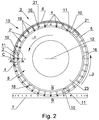
- Fig. 2 shows a fragment of the bead feeding unit 1 according to the invention in the first embodiment.
- the bead feeding unit 3 and the unit 13 for transferring the beads 2 to the wheel 7 are shown.
- the bead feeding unit 3 is provided with a plurality of channels 4, whereas all channels 4 are filled with the beads 2 (in view of proportionally small dimensions of the beads, in the drawing they are shown in the form of shaded small circles).
- the elements fastening the channels 4 to the frame of the unit 1 and the drive elements are not shown.
- the bead feeding unit 3 is provided with a rotatable feeding means 8 in the form of a cam 23 comprising pushing segments 10 having pushing edges 11, whereas the cam 8 rotates with a speed ⁇ 1 around the axis of rotation 12, and the pushing segments 10 move along a circular path in the area of the outlets of the channels 4 being the area of the holding pockets 14.
- the guiding channels 19 together with the pockets 18 are situated in the disc 6 which rotates at the speed ⁇ 2 lower than the speed ⁇ 1.
- the motion of the segments 10 disposed on the rotating cam 23 and the motion of the pockets 18 are synchronized in order to enable inserting the beads 2' into the pockets 18 situated at the beginning of the channels 19, whereas the speeds ⁇ 1 and ⁇ 2 are selected in such a way that during the operation of the unit the pushing segments 10 cause inserting the beads into successive pockets 18 in the guiding channels 19. It may be achieved when the guiding channel 19 is situated relative to the outlet of the channel 4 and the first holding pocket 14 in such a way that renders transferring of a bead 2' possible, for example the pocket 18 receiving the bead may be situated substantially radially to the holding pocket 14.
- the unit is shown in a situation where several beads 2 have already been placed into the guiding channels 19, and some of the beads have been placed in the removing pockets 21 by centrifugal force.
- Fig. 3 shows a sectional view of any channel 4 where for example in Fig. 2 the section was marked as A-A.
- the lowermost bead 2' in the bead column is situated in the holding pocket 14 disposed at the outlet of the channel 4, limited from below by the disc 15, and on the sides by the disc 5 and the circumferential edge 16 of the cam 23.
- Fig. 4 shows a sectional view of the channel 4 when a piece of a damaged bead 26 of the channel 4 gets into the pocket 14, and the bead 13 feeding unit does not have a cleaning element 25.
- the fragment of the damaged bead 26 lying at the bottom of the holding pocket 14 causes an improper arrangement of the bead 2' in the pocket, which results in the bead being damaged when pushing it by the feeding means into the guiding channel 19.
- the feeding means 23 is provided with the cleaning element 25 shown in the successive figures.
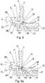
- Fig. 5 shows a sectional view of the channel 4 in a situation where the pushing segment 10, moving along a circular path in the area of the first holding pockets 14, during the rotation of the cam 23 has passed a successive pocket 14 beneath a successive channel 4 and caused pushing of the bead 2' out of the first pocket 14 to the second receiving pocket 18 in the area between the first guiding disc 5 and the second guiding disc 6.
- the cleaning element 25 is inserted into the pocket in order to clean the holding pocket 14 of the pieces of damaged beads 26 or other deposited impurities, which is successively shown in Figs.5a , 5b and 5c .
- the method of feeding beads 2 in the bead feeding unit 3 in the tobacco industry, the unit being provided with supply channels 4 feeding streams of the beads 2, consists in conveying the beads 2 along the supply channel 4 and then placing the bead 2' from individual supply channels 4 in the first holding pockets 14. After placing the beads 2' in the pockets 14 by the means of movable means 8, the beads 2' are fed from the holding pockets 14 to the receiving pockets 18 of the bead 13 transferring unit. Then the beads 2' are taken from the receiving pockets 18 by means of the guiding discs 5, 6 and transferred to the removing pockets 21 through the guiding channels 19. After transferring the beads 2' from the holding pockets 14 to the receiving pockets 18, the holding pockets 14 are cleaned by means of at least one cleaning element 25.
- the cleaning element 25 in the form of a stable projection which sinks so deep into the pocket 14 that it may completely remove, grind or move a fragment of damaged bead so that it may be later more easily removed from the pocket. It is also possible that the cleaning element 25 takes the shape of rigid brushes or another elastic element which will sink into the pocket 14 and remove any impurities.
- the cleaning element 25 in this embodiment is fastened to the feeding means 8 in the form of the rotatable cam 23 in the area of the pushing segment 10.
- An inclination of the guiding channel 19 which may be achieved by a conical shape of the discs 5 and 6 is also possible. Any fragmented pieces of the damaged bead 26 may be removed from the pocket 14 using the vacuum through the channel 27 situated in the disc 15 ( Fig.5b ), blown by compressed air by means of a nozzle 29 out of the holding pocket 14 as shown in Fig. 5c or removed by vacuum through the channel 28 (shown in Fig 7 ) situated behind the cleaning element 25 in the cam 23 of the transferring unit 13.
- the cleaning element takes the shape of the channel 27 situated in the disc 15 which could fulfil two functions: by supplying vacuum hold the bead 2' in the pocket 14 until it is pushed by the cam 23, and after transferring it to the channel 19, by supplying for example compressed air, clean the pocket 14 before feeding the next bead to it. Then the bead 2' is conveyed substantially horizontally in the guiding channel 19, transferred to the receiving pocket 21 and further to the pocket on the delivery wheel 7 as shown in Fig. 6
- Fig. 7 shows a magnified fragment of the area C of Fig.2 of a part of the bead feeding unit 13 in a top view in which the precise position of the cleaning element 25 on the feeding means 8 is visible.
- the cleaning element 25 is situated in the region of the pushing edge 11 so that just after pushing the bead 2 out of the holding pocket 14 situated beneath the channel 4 it may sink into the emptied pocket 14 before the next bead from the channel 4 enters the holding pocket 14. It may be achieved only if between the channel 4 with the bead 2 stream and the holding pocket 14 the pushing segment 10 of the cam 23 is situated which, when pushing the bead 2 to the channel 19, will stop the flow of the next bead from the channel 4 to the pocket 14.
- a channel 28 supplying compressed air or vacuum in order to remove the pieces of the damaged bead 26 fragmented by the cleaning element 25.
Landscapes
- Engineering & Computer Science (AREA)
- Mechanical Engineering (AREA)
- Chemical & Material Sciences (AREA)
- Materials Engineering (AREA)
- Cigarettes, Filters, And Manufacturing Of Filters (AREA)
- Specific Conveyance Elements (AREA)
- Feeding Of Articles To Conveyors (AREA)
- Manufacturing Of Cigar And Cigarette Tobacco (AREA)
Abstract
Description
- The object of the application is a bead feeding method and a bead feeding unit used in the filters of the tobacco industry products, in particular cigarettes.
- This invention concerns feeding of spherical or oval objects which are subsequently placed into filter material. For the sake of simplification, such objects will be hereinafter referred to as beads. A known product on the market are cigarettes the filters of which are provided with beads containing aromatic or odorous substances. The substances contained in the beads are released during smoking or yet before lighting up a cigarette by squeezing of the filter which results in crushing the bead.
- In the production process, a problem which is difficult to solve and at the same time very significant is the feeding of individual beads to a machine forming filters at great speeds in a way which guarantees that the beads remain undamaged, the flow in the pockets holding the beads remains undisturbed and a high feeding efficiency is maintained, i.e. each manufactured filter actually contains a bead.
- In known bead feeders, tubes for feeding the beads to the area from which they are transferred to a bead delivery wheel are used, whereas the function of the said wheel is to place the delivered beads into the filter material.
- In the
US patent 7,975,877B2 a bead feeder is disclosed in which the bead feeding unit is provided with a plurality of tubes which are radially connected with a cylindrical bowl, whereas the tubes rotate together with the bowl, and the beads are picked up by a vacuum bead transfer wheel from pockets situated at the outlets of the tubes, and then transferred to a bead delivery wheel from which they are delivered to the filter material. - The document
WO 2009/071271 discloses a bead feeder in which the bead feeding unit is provided with tubes rotating with the bowl, whereas the beads are fed to a bead delivery wheel after separating the lowermost bead from those situated above it using a stationary arched wedge-ended element. After passing through the passageway the beads are fed to the pockets of the bead delivery wheel which delivers them to the filter material. - The document
WO 2009/071272 discloses a similar bead feeder, whereas the beads are fed to the bead delivery wheel using two discs having a plurality of openings and rotating relative to each other, and a bead is fed after aligning respective openings directly on top of each other and forming successive passageways to the pockets of the bead delivery wheel. - The
US patent 7,833,146B2 shows an apparatus for feeding beads through curved tubes from a bowl directly to the bead delivery wheel, where the tubes rotate together with the bead bowl, and the beads are picked up from the bowl by vacuum transfer. - The
patent EP 2 622 973B1 shows an apparatus for feeding beads in individual streams from the bowl through channels to pockets situated on the receiving wheel, then the beads are transferred to the pockets situated on the delivery wheel from which they are delivered to the filter material. - The bead feeders presented above require that during the operation the bead feeding tubes and the bead holding pockets must be free of dirt in order to realize an undisturbed flow.
- The objective of the invention is to develop a bead feeding method and a bead feeder ensuring an undisturbed flow through the channels and the bead holding pockets.
- The object of the invention is a bead feeding unit in a production machine in the tobacco industry, provided with a unit of supply channels feeding streams of beads from a store to holding pockets situated at the outlets of the supply channels, a transferring unit comprising at least one guiding disc and a movable feeding means adapted to direct the beads to receiving pockets of the transferring unit. The unit according to the invention is characterised in that the transferring unit has at least one cleaning element adapted to clean the holding pockets.
- The unit according to the invention is further characterised in that the cleaning element is situated on the movable feeding means.
- The unit according to the invention is further characterised in that the cleaning element is situated on the movable feeding means on a cam underneath a pushing segment.
- The unit according to the invention is further characterised in that the cleaning element has the form of a scraper adapted to sink into a holding pocket or a nozzle blowing compressed air or a sucking mouthpiece using vacuum or a combination of the above means.
- The unit according to the invention is further characterised in that the movable feeding means are situated between two guiding discs.
- The unit according to the invention is further characterised in that the movable feeding means have channels supplying compressed air to the holding pockets to the cleaning element.
- The unit according to the invention is further characterised in that the movable feeding means have channels supplying vacuum to the holding pockets to the cleaning element.
- The unit according to the invention is further characterised in that the channels supplying the compressed air or vacuum are situated behind the cleaning element.
- The unit according to the invention is further characterised in that the movable feeding means have at least one pushing edge, whereas the cleaning element is situated on the movable feeding means behind the pushing edge.
- The object of the invention is also a method of feeding the beads in a bead feeding unit in the tobacco industry, the unit being provided with supply channels feeding streams of beads, comprising the steps in which: the beads are transferred along supply channels; the beads from individual supply channels are placed into first holding pockets. Then by means of movable means the beads are fed from the holding pockets to receiving pockets of the bead transferring unit. The beads are taken from the receiving pockets by means of at least one guiding disc, and the beads are transferred to removing pockets through guiding channels. The method according to the invention is characterised in that after transferring the beads from the holding pockets to the receiving pockets the holding pockets are cleaned by means of at least one cleaning element.
- The method according to the invention is characterised in that the holding pockets are cleaned by inserting the cleaning element into such pockets.
- The method according to the invention is characterised in that after inserting the cleaning element into the holding pockets compressed air is supplied in order to blow out the dirt from the holding pockets.
- The method according to the invention is characterised in that after inserting the cleaning element into the holding pockets vacuum is supplied in order to suck the dirt from the holding pockets.
- The object of the invention is further a method of feeding beads in a feeding unit in a tobacco industry machine, comprising the steps wherein: the beads are transferred along individual supply channels from a bead store to holding pockets of a bead feeding unit. Then the beads from individual supply channels are placed into first holding pockets. By means of a movable means the beads are fed from the holding pockets to receiving pockets of a bead transferring unit. The beads are taken from the receiving pockets by means of at least one guiding disc, and the beads are transferred to removing pockets through guiding channels. The method according to the invention is characterised in that before placing the beads in the holding pockets and before transferring the beads from the holding pockets to the receiving pockets the holding pockets are cleaned by means of at least one cleaning element.
- The bead feeding unit according to the invention is provided with cleaning elements adapted to clean the bead holding pockets so that the number of machine stoppages resulting from dirty or blocked holding pockets was significantly reduced. Furthermore, such solution ensures that each manufactured filter will contain a bead.
- The object of the invention was shown in detail in a preferred embodiment in a drawing in which:
-
Fig. 1 shows a bead feeding unit in a perspective view, -
Fig. 2 shows a fragment of the bead feeding unit in a first embodiment, in a top view, -
Fig. 3 shows a sectional view of a holding pocket in a first embodiment of a guiding channel, marked inFig. 2 as A-A, after pushing a bead out of the holding pocket, -
Fig. 4 shows a sectional view of the holding pocket after inserting the bead into the holding pocket with a piece of a damaged bead, -
Fig.5 shows a sectional view of the holding pocket of the bead feeding unit with a cleaning element, -
Fig.5a shows a sectional view of the holding pocket of the bead feeding unit with the cleaning element grinding a damaged bead in the holding pocket, -
Fig. 5b shows a sectional view of the holding pocket of the bead feeding unit when removing a damaged bead from the holding pocket through a channel with the use of vacuum, -
Fig. 5c shows a sectional view of the holding pocket of the bead feeding unit when removing a damaged bead from the holding pocket by means of compressed air, -
Fig. 6 shows a sectional view of a receiving pocket, marked inFig. 2 as B-B, when feeding the bead onto a receiving wheel, -
Fig. 7 shows a magnified fragment C of the bead feeding unit ofFig.2 in a top view, -
Fig. 1 shows abead 2feeding unit 1 provided with astore 2A for storingbeads 2, a beadstream feeding unit 3, aunit 13 for transferring the beads to adelivery wheel 7 and thewheel 7 delivering thebeads 2 to a continuous filter material conveyed along afunnel 9. The filter material may also have the form of segments transported at intervals on the wrapper between which the beads are inserted. For the sake of simplification, the elements fastening individual units were not shown. - The
bead 2feeding unit 3 is provided with a plurality of stationary channels in the form ofchannels 4 to whichbeads 2 from thestore 2A are supplied, whereas onebead 2 above the inlet of one of the channels was shown. At the outlets of thechannels 4, there are situated first holding pockets 14 (Fig. 3 ) from which the beads are transferred to second receiving pockets 18 (Fig. 4 ) which receive thebeads 2; theseconds pockets 18 are situated in the area between a first guidingdisc 5 and a second guidingdisc 6, whereas the guidingdiscs unit 13 for transferring thebeads 2 to thedelivery wheel 7. After passing through a guidingchannel 19 between thedisc 5 and thedisc 6, thebeads 2 are transferred further to receivingpockets 21, and then placed into the pockets on the circumference of thedelivery wheel 7 which places thebeads 2 into a filter material conveyed in the funnel 9 (Fig. 1 ). A thick broken line shows the distance covered by the bead in all embodiments described herein.Such bead 2 moves from thestore 2A downwards in one of thechannels 4 to theholding pocket 14, in the drawing, this section of the distance is marked with X1. The next section of the distance from theholding pocket 14 via the receivingpocket 18 to the removingpocket 21 is marked with X2. In the next section of the distance X3 the bead is conveyed along an arc in thepocket 21 to a place at which the bead is transferred onto thedelivery wheel 7. In the section X4, the bead is further conveyed in the pocket on thewheel 7. Then it is placed into the filter material within thefunnel 9 and further moves along the last section of the distance X5. -
Fig. 2 shows a fragment of thebead feeding unit 1 according to the invention in the first embodiment. In a top view, thebead feeding unit 3 and theunit 13 for transferring thebeads 2 to thewheel 7 are shown. Thebead feeding unit 3 is provided with a plurality ofchannels 4, whereas allchannels 4 are filled with the beads 2 (in view of proportionally small dimensions of the beads, in the drawing they are shown in the form of shaded small circles). For the sake of simplification, the elements fastening thechannels 4 to the frame of theunit 1 and the drive elements are not shown. Thebead feeding unit 3 is provided with a rotatable feeding means 8 in the form of acam 23 comprising pushingsegments 10 having pushingedges 11, whereas thecam 8 rotates with a speed ω1 around the axis ofrotation 12, and the pushingsegments 10 move along a circular path in the area of the outlets of thechannels 4 being the area of the holding pockets 14. In the embodiment shown, the guidingchannels 19 together with thepockets 18 are situated in thedisc 6 which rotates at the speed ω2 lower than the speed ω1. During the operation of the bead feeding unit, the motion of thesegments 10 disposed on the rotatingcam 23 and the motion of thepockets 18 are synchronized in order to enable inserting the beads 2' into thepockets 18 situated at the beginning of thechannels 19, whereas the speeds ω1 and ω2 are selected in such a way that during the operation of the unit the pushingsegments 10 cause inserting the beads intosuccessive pockets 18 in the guidingchannels 19. It may be achieved when the guidingchannel 19 is situated relative to the outlet of thechannel 4 and the first holdingpocket 14 in such a way that renders transferring of a bead 2' possible, for example thepocket 18 receiving the bead may be situated substantially radially to the holdingpocket 14. The unit is shown in a situation whereseveral beads 2 have already been placed into the guidingchannels 19, and some of the beads have been placed in the removingpockets 21 by centrifugal force. -
Fig. 3 shows a sectional view of anychannel 4 where for example inFig. 2 the section was marked as A-A. The lowermost bead 2' in the bead column is situated in the holdingpocket 14 disposed at the outlet of thechannel 4, limited from below by thedisc 15, and on the sides by thedisc 5 and thecircumferential edge 16 of thecam 23. -
Fig. 4 shows a sectional view of thechannel 4 when a piece of a damagedbead 26 of thechannel 4 gets into thepocket 14, and thebead 13 feeding unit does not have acleaning element 25. The fragment of the damagedbead 26 lying at the bottom of the holdingpocket 14 causes an improper arrangement of the bead 2' in the pocket, which results in the bead being damaged when pushing it by the feeding means into the guidingchannel 19. In order to prevent it, the feeding means 23 is provided with the cleaningelement 25 shown in the successive figures. -
Fig. 5 shows a sectional view of thechannel 4 in a situation where the pushingsegment 10, moving along a circular path in the area of the first holding pockets 14, during the rotation of thecam 23 has passed asuccessive pocket 14 beneath asuccessive channel 4 and caused pushing of the bead 2' out of thefirst pocket 14 to the second receivingpocket 18 in the area between thefirst guiding disc 5 and thesecond guiding disc 6. After pushing the bead 2' out of the holdingpocket 14, the cleaningelement 25 is inserted into the pocket in order to clean the holdingpocket 14 of the pieces of damagedbeads 26 or other deposited impurities, which is successively shown inFigs.5a ,5b and 5c . The method of feedingbeads 2 in thebead feeding unit 3 in the tobacco industry, the unit being provided withsupply channels 4 feeding streams of thebeads 2, consists in conveying thebeads 2 along thesupply channel 4 and then placing the bead 2' fromindividual supply channels 4 in the first holding pockets 14. After placing the beads 2' in thepockets 14 by the means ofmovable means 8, the beads 2' are fed from the holdingpockets 14 to the receiving pockets 18 of thebead 13 transferring unit. Then the beads 2' are taken from the receivingpockets 18 by means of the guidingdiscs pockets 21 through the guidingchannels 19. After transferring the beads 2' from the holdingpockets 14 to the receiving pockets 18, the holdingpockets 14 are cleaned by means of at least onecleaning element 25. Since the beads used in the tobacco industry contain taste and aromatic substances, their damage may result in such substance getting into the holdingpocket 14, thechannels 4 or the guidingchannel 19, thus enabling the pieces of damaged beads and other dirt to stick around. Therefore, an advantageous solution will be the cleaningelement 25 in the form of a stable projection which sinks so deep into thepocket 14 that it may completely remove, grind or move a fragment of damaged bead so that it may be later more easily removed from the pocket. It is also possible that thecleaning element 25 takes the shape of rigid brushes or another elastic element which will sink into thepocket 14 and remove any impurities. The cleaningelement 25 in this embodiment is fastened to the feeding means 8 in the form of therotatable cam 23 in the area of the pushingsegment 10. An inclination of the guidingchannel 19 which may be achieved by a conical shape of thediscs bead 26 may be removed from thepocket 14 using the vacuum through thechannel 27 situated in the disc 15 (Fig.5b ), blown by compressed air by means of anozzle 29 out of the holdingpocket 14 as shown inFig. 5c or removed by vacuum through the channel 28 (shown inFig 7 ) situated behind thecleaning element 25 in thecam 23 of the transferringunit 13. It is also possible that the cleaning element takes the shape of thechannel 27 situated in thedisc 15 which could fulfil two functions: by supplying vacuum hold the bead 2' in thepocket 14 until it is pushed by thecam 23, and after transferring it to thechannel 19, by supplying for example compressed air, clean thepocket 14 before feeding the next bead to it. Then the bead 2' is conveyed substantially horizontally in the guidingchannel 19, transferred to the receivingpocket 21 and further to the pocket on thedelivery wheel 7 as shown inFig. 6 -
Fig. 7 shows a magnified fragment of the area C ofFig.2 of a part of thebead feeding unit 13 in a top view in which the precise position of thecleaning element 25 on the feeding means 8 is visible. The cleaningelement 25 is situated in the region of the pushingedge 11 so that just after pushing thebead 2 out of the holdingpocket 14 situated beneath thechannel 4 it may sink into the emptiedpocket 14 before the next bead from thechannel 4 enters the holdingpocket 14. It may be achieved only if between thechannel 4 with thebead 2 stream and the holdingpocket 14 the pushingsegment 10 of thecam 23 is situated which, when pushing thebead 2 to thechannel 19, will stop the flow of the next bead from thechannel 4 to thepocket 14. Moreover, in the feeding means 8 behind thecleaning element 25 there may be situated achannel 28 supplying compressed air or vacuum in order to remove the pieces of the damagedbead 26 fragmented by the cleaningelement 25.
Claims (14)
- A bead feeding unit (1) in a production machine in the tobacco industry, provided with
a unit of supply channels (4) feeding streams of beads (2) from a store (2A) to holding pockets (14) situated at the outlets of the supply channels (4),
a transferring unit (13) comprising at least one guiding disc (5, 6) and a movable feeding means (8) adapted to direct the beads to receiving pockets (18) of the transferring unit (13)
characterised in that
the transferring unit (13) has at least one cleaning element (25) adapted to clean the holding pockets (14). - The unit (1) as in claim 1, characterised in that the cleaning element (25) is situated on the movable feeding means (8).
- The unit (1) as in claim 2, characterised in that the cleaning element (25) is situated on the movable feeding means (8) on a cam (23) underneath a pushing segment (10).
- The unit (1) as in claim 1-3, characterised in that the cleaning element (25) has the form of a scraper adapted to sink into the holding pocket (14) or a nozzle blowing compressed air or a sucking mouthpiece using vacuum or a combination of the above means.
- The unit (1) as in claim 1-4, characterised in that the movable feeding means (8) are situated between two guiding discs (5,6).
- The unit (1) as in claim 1-5, characterised in that the movable feeding means (8) have channels supplying compressed air to the holding pockets (14) to the cleaning element (25).
- The unit (1) as in claim 1-5, characterised in that the movable feeding means (8) have channels supplying vacuum to the holding pockets (14) to the cleaning element (25).
- The unit (1) as in claim 6-7, characterised in that the channels supplying compressed air or vacuum are situated behind the cleaning element (25).
- The unit (1) as in claim 1-7, characterised in that the movable feeding means (8) have at least one pushing edge (11), whereas the cleaning element (25) is situated on the movable feeding means (8) behind the pushing edge (11).
- A method of feeding beads (2) in a bead feeding unit in the tobacco industry, the unit being provided with supply channels feeding streams of beads, comprising steps wherein:the beads are transferred along supply channels;the beads from individual supply channels are placed into first holding pockets (14);by a movable means (8) the beads are fed from the holding pockets (14) to receiving pockets (18) of the bead transferring unit (13);the beads are taken from the receiving pockets (18) by at least one guiding disc (5,6) and transferred to removing pockets (21) through guiding channels (19),characterised in thatafter transferring the beads from the holding pockets (14) to the receiving pockets (18) the holding pockets (14) are cleaned by at least one cleaning element (25).
- The method as in claim 10, characterised in that the holding pockets (14) are cleaned by inserting the cleaning element (25) into such pockets.
- The method as in claim 10-11, characterised in that after inserting the cleaning element (25) into the holding pockets (14) compressed air is supplied in order to blow out the dirt from the holding pockets (14).
- The method as in claim 10-11, characterised in that after inserting the cleaning element (25) into the holding pockets (14) vacuum is supplied in order to suck the dirt from the holding pockets (14).
- A method of feeding beads in a feeding unit in a tobacco industry machine comprising steps wherein:the beads are transferred along individual supply channels from a bead store to holding pockets (14) of a bead feeding unit (3);the beads from individual channels are placed into first holding pockets (14);by a movable means (8) the beads are fed from the holding pockets (14) to receiving pockets (18) of a bead transferring unit (13);the beads are taken from the receiving pockets (18) by at least one guiding disc (5, 6) and the beads are transferred to removing pockets (21) through guiding channels (19),characterised in that
before placing the beads in the holding pockets (14) and before transferring the beads from the holding pockets (14) to the receiving pockets (18) the holding pockets (14) are cleaned by at least one cleaning element (25).
Priority Applications (6)
| Application Number | Priority Date | Filing Date | Title |
|---|---|---|---|
| EP18212859.5A EP3669675B1 (en) | 2018-12-17 | 2018-12-17 | Bead feeding method and bead feeding unit |
| JP2019204803A JP7316195B2 (en) | 2018-12-17 | 2019-11-12 | Bead supply method and bead supply unit |
| US15/929,171 US11219241B2 (en) | 2018-12-17 | 2019-11-26 | Bead feeding method and bead feeding unit |
| CN201911189008.6A CN111319947B (en) | 2018-12-17 | 2019-11-28 | Bead feeding method and bead feeding unit |
| KR1020190157045A KR20200075739A (en) | 2018-12-17 | 2019-11-29 | Bead feeding method and bead feeding unit |
| BR102019026726-7A BR102019026726A2 (en) | 2018-12-17 | 2019-12-14 | globule feeder unit on a production machine in the tobacco industry, method for feeding globules on a globule feeder unit on the tobacco industry and method for feeding globules on a feeder unit on a tobacco industry machine |
Applications Claiming Priority (1)
| Application Number | Priority Date | Filing Date | Title |
|---|---|---|---|
| EP18212859.5A EP3669675B1 (en) | 2018-12-17 | 2018-12-17 | Bead feeding method and bead feeding unit |
Publications (2)
| Publication Number | Publication Date |
|---|---|
| EP3669675A1 true EP3669675A1 (en) | 2020-06-24 |
| EP3669675B1 EP3669675B1 (en) | 2025-03-05 |
Family
ID=65279372
Family Applications (1)
| Application Number | Title | Priority Date | Filing Date |
|---|---|---|---|
| EP18212859.5A Active EP3669675B1 (en) | 2018-12-17 | 2018-12-17 | Bead feeding method and bead feeding unit |
Country Status (6)
| Country | Link |
|---|---|
| US (1) | US11219241B2 (en) |
| EP (1) | EP3669675B1 (en) |
| JP (1) | JP7316195B2 (en) |
| KR (1) | KR20200075739A (en) |
| CN (1) | CN111319947B (en) |
| BR (1) | BR102019026726A2 (en) |
Cited By (1)
| Publication number | Priority date | Publication date | Assignee | Title |
|---|---|---|---|---|
| CN117163658A (en) * | 2023-11-02 | 2023-12-05 | 苏州明益信智能设备有限公司 | Battery case cleaning and pretreatment automated conveying equipment |
Families Citing this family (3)
| Publication number | Priority date | Publication date | Assignee | Title |
|---|---|---|---|---|
| EP3944774B1 (en) * | 2020-07-29 | 2025-07-02 | International Tobacco Machinery Poland Sp. z o.o. | Feeding unit for feeding beads and apparatus for manufactoring rods |
| WO2023056306A1 (en) * | 2021-09-28 | 2023-04-06 | Mikron Corporation Denver | Lyophilized bead handling |
| CN115989893B (en) * | 2023-02-17 | 2024-08-09 | 湖北中烟工业有限责任公司 | A bead retrieval plate structure and vertical bead implantation system |
Citations (7)
| Publication number | Priority date | Publication date | Assignee | Title |
|---|---|---|---|---|
| US20070068540A1 (en) * | 2005-09-23 | 2007-03-29 | Thomas Timothy F | Equipment for insertion of objects into smoking articles |
| WO2009071272A1 (en) | 2007-12-05 | 2009-06-11 | Philip Morris Products S.A. | Bead feeder |
| WO2009071271A1 (en) | 2007-12-05 | 2009-06-11 | Philip Morris Products S.A. | Bead feeder |
| US7833146B2 (en) | 2003-09-12 | 2010-11-16 | R.J. Reynolds Tobacco Company | Method and apparatus for incorporating objects into cigarette filters |
| US20110053745A1 (en) * | 2009-08-31 | 2011-03-03 | Plamen Iliev | Apparatus and method for insertion of capsules into filter tows |
| US7975877B2 (en) | 2007-08-10 | 2011-07-12 | Philip Morris Usa Inc. | Bead feeder |
| EP2622973B1 (en) | 2012-01-18 | 2017-03-15 | International Tobacco Machinery Poland Sp. z o.o. | Bead feeding method and bead feeding unit |
Family Cites Families (20)
| Publication number | Priority date | Publication date | Assignee | Title |
|---|---|---|---|---|
| CN2066377U (en) * | 1990-02-05 | 1990-11-28 | 青岛粉末冶金厂 | Roller cutter |
| JPH0670739A (en) * | 1992-08-24 | 1994-03-15 | Japan Tobacco Inc | Machine for producing filter rod |
| JPH10311196A (en) * | 1997-05-12 | 1998-11-24 | Yachiyo Koken:Kk | Pressing feeding body device in propeller |
| WO2003016137A1 (en) | 2001-08-17 | 2003-02-27 | Philip Morris Products, S.A. | Dual station applicator wheels for filling cavities with metered amounts of particulate material |
| ES2282499T3 (en) | 2002-12-19 | 2007-10-16 | Filtrona International Limited | PROCESS AND APPLIANCE FOR HIGH-SPEED FILLING OF COMPOSITE FILTERS FOR CIGARETTES. |
| CN1970409B (en) * | 2006-12-08 | 2010-08-11 | 陆昕 | Automatic quantitative feeder |
| WO2012057255A1 (en) | 2010-10-29 | 2012-05-03 | 日本たばこ産業株式会社 | Granular material supply device and granular material supply method |
| ZA201008663B (en) * | 2010-12-01 | 2014-08-27 | Tobacco Res And Dev Inst (Pty) Ltd | Feed mechanism |
| PL222242B1 (en) * | 2012-01-18 | 2016-07-29 | Int Tobacco Machinery Poland Spółka Z Ograniczoną Odpowiedzialnością | Method and system for the transmission of capsules |
| PL222268B1 (en) * | 2012-01-18 | 2016-07-29 | Int Tobacco Machinery Poland Spółka Z Ograniczoną Odpowiedzialnością | Method and a device for administration of capsules |
| PL218090B1 (en) * | 2012-07-04 | 2014-10-31 | Int Tobacco Machinery Poland | Method and device for irregular transmission of capsules |
| US10569969B2 (en) * | 2013-02-26 | 2020-02-25 | Philip Morris Usa Inc. | Bead feeder |
| CN105188423B (en) | 2013-03-19 | 2019-05-31 | 菲利普莫里斯生产公司 | Apparatus and method for filling cavities with particulate material |
| CN204250865U (en) * | 2014-10-31 | 2015-04-08 | 黄世茭 | A kind of automatic material selecting bead loading machine |
| PL411548A1 (en) * | 2015-03-12 | 2016-09-26 | International Tobacco Machinery Poland Spółka Z Ograniczoną Odpowiedzialnością | A unit feeding the loose material and method for feeding the loose material |
| PL234036B1 (en) * | 2016-09-06 | 2020-01-31 | Int Tobacco Machinery Poland Spolka Z Ograniczona Odpowiedzialnoscia | Cleaning unit of the tobacco industry machine designed for manufacturing the multiple-segment filter bars and method for cleaning the bar-like elements train |
| CN206994408U (en) * | 2017-07-21 | 2018-02-13 | 许昌宏昌实业有限公司 | A kind of rotation for cigarette machine U-turn drum wheel refers to |
| CN107585514B (en) * | 2017-10-04 | 2019-02-22 | 杨朴 | A sealed disc feeder |
| CN107626630A (en) * | 2017-10-11 | 2018-01-26 | 山东中烟工业有限责任公司 | A kind of filter tip inserting machine push plate drum automatic cleaning apparatus and method of work |
| CN108125273B (en) * | 2017-12-21 | 2020-12-11 | 山东将军烟草新材料科技有限公司 | Double-bead-blasting filter rod preparation air distribution plate and preparation device |
-
2018
- 2018-12-17 EP EP18212859.5A patent/EP3669675B1/en active Active
-
2019
- 2019-11-12 JP JP2019204803A patent/JP7316195B2/en active Active
- 2019-11-26 US US15/929,171 patent/US11219241B2/en not_active Expired - Fee Related
- 2019-11-28 CN CN201911189008.6A patent/CN111319947B/en active Active
- 2019-11-29 KR KR1020190157045A patent/KR20200075739A/en not_active Ceased
- 2019-12-14 BR BR102019026726-7A patent/BR102019026726A2/en not_active Application Discontinuation
Patent Citations (7)
| Publication number | Priority date | Publication date | Assignee | Title |
|---|---|---|---|---|
| US7833146B2 (en) | 2003-09-12 | 2010-11-16 | R.J. Reynolds Tobacco Company | Method and apparatus for incorporating objects into cigarette filters |
| US20070068540A1 (en) * | 2005-09-23 | 2007-03-29 | Thomas Timothy F | Equipment for insertion of objects into smoking articles |
| US7975877B2 (en) | 2007-08-10 | 2011-07-12 | Philip Morris Usa Inc. | Bead feeder |
| WO2009071272A1 (en) | 2007-12-05 | 2009-06-11 | Philip Morris Products S.A. | Bead feeder |
| WO2009071271A1 (en) | 2007-12-05 | 2009-06-11 | Philip Morris Products S.A. | Bead feeder |
| US20110053745A1 (en) * | 2009-08-31 | 2011-03-03 | Plamen Iliev | Apparatus and method for insertion of capsules into filter tows |
| EP2622973B1 (en) | 2012-01-18 | 2017-03-15 | International Tobacco Machinery Poland Sp. z o.o. | Bead feeding method and bead feeding unit |
Cited By (2)
| Publication number | Priority date | Publication date | Assignee | Title |
|---|---|---|---|---|
| CN117163658A (en) * | 2023-11-02 | 2023-12-05 | 苏州明益信智能设备有限公司 | Battery case cleaning and pretreatment automated conveying equipment |
| CN117163658B (en) * | 2023-11-02 | 2024-02-02 | 苏州明益信智能设备有限公司 | Automatic conveying equipment for cleaning pretreatment of battery shell |
Also Published As
| Publication number | Publication date |
|---|---|
| CN111319947A (en) | 2020-06-23 |
| CN111319947B (en) | 2023-09-05 |
| US11219241B2 (en) | 2022-01-11 |
| JP2020096585A (en) | 2020-06-25 |
| BR102019026726A2 (en) | 2020-07-07 |
| JP7316195B2 (en) | 2023-07-27 |
| KR20200075739A (en) | 2020-06-26 |
| US20200187554A1 (en) | 2020-06-18 |
| EP3669675B1 (en) | 2025-03-05 |
Similar Documents
| Publication | Publication Date | Title |
|---|---|---|
| US11219241B2 (en) | Bead feeding method and bead feeding unit | |
| EP2622973B1 (en) | Bead feeding method and bead feeding unit | |
| EP2617665B1 (en) | Bead feeding method and bead feeder | |
| US8869969B2 (en) | Method and unit for feeding beads | |
| KR101504386B1 (en) | Method of compiling groups of segments in a process of producing multisegment filters and apparatus for preparing and compiling segments in groups in a process of producing multisegment filters | |
| JP5438237B2 (en) | Method and unit for uneven transfer of beads | |
| CN104203014B (en) | Cleaning system for a roller conveyor of a plant for supplying filter segments to a multi-segment filter manufacturing plant and method of cleaning the roller conveyor | |
| EP2750525B1 (en) | Tobacco reclaim from waste cigarettes | |
| RU2759456C2 (en) | Device and feeding method intended for feeding spherical objects in tobacco industry equipment | |
| EP3089600B1 (en) | Apparatus and method for introducing objects into a flow of filter material | |
| PL244138B1 (en) | An orienting and dispensing system for feeding cigarettes and longitudinally orienting cigarettes, a tobacco recovery device comprising the system, a method for feeding cigarettes and longitudinally orienting cigarettes, and a method for recovering tobacco | |
| CN107215636B (en) | Cleaning system for conveying and storage equipment with adjustable capacity for tobacco industry rod-like elements | |
| RU2786907C1 (en) | Granule supply method and granule supply unit | |
| EP3509444A1 (en) | A cleaning unit, a tobacco industry machine for producing multi-segment filter rods and a method for cleaning a train of rod-like elements | |
| EP1488710A2 (en) | A cigarette maker | |
| PL239765B1 (en) | Capsule feed method and an assembly for capsule feed |
Legal Events
| Date | Code | Title | Description |
|---|---|---|---|
| PUAI | Public reference made under article 153(3) epc to a published international application that has entered the european phase |
Free format text: ORIGINAL CODE: 0009012 |
|
| STAA | Information on the status of an ep patent application or granted ep patent |
Free format text: STATUS: THE APPLICATION HAS BEEN PUBLISHED |
|
| AK | Designated contracting states |
Kind code of ref document: A1 Designated state(s): AL AT BE BG CH CY CZ DE DK EE ES FI FR GB GR HR HU IE IS IT LI LT LU LV MC MK MT NL NO PL PT RO RS SE SI SK SM TR |
|
| AX | Request for extension of the european patent |
Extension state: BA ME |
|
| STAA | Information on the status of an ep patent application or granted ep patent |
Free format text: STATUS: REQUEST FOR EXAMINATION WAS MADE |
|
| 17P | Request for examination filed |
Effective date: 20201229 |
|
| RBV | Designated contracting states (corrected) |
Designated state(s): AL AT BE BG CH CY CZ DE DK EE ES FI FR GB GR HR HU IE IS IT LI LT LU LV MC MK MT NL NO PL PT RO RS SE SI SK SM TR |
|
| STAA | Information on the status of an ep patent application or granted ep patent |
Free format text: STATUS: EXAMINATION IS IN PROGRESS |
|
| 17Q | First examination report despatched |
Effective date: 20221202 |
|
| GRAP | Despatch of communication of intention to grant a patent |
Free format text: ORIGINAL CODE: EPIDOSNIGR1 |
|
| STAA | Information on the status of an ep patent application or granted ep patent |
Free format text: STATUS: GRANT OF PATENT IS INTENDED |
|
| INTG | Intention to grant announced |
Effective date: 20240515 |
|
| GRAJ | Information related to disapproval of communication of intention to grant by the applicant or resumption of examination proceedings by the epo deleted |
Free format text: ORIGINAL CODE: EPIDOSDIGR1 |
|
| STAA | Information on the status of an ep patent application or granted ep patent |
Free format text: STATUS: EXAMINATION IS IN PROGRESS |
|
| INTC | Intention to grant announced (deleted) | ||
| GRAP | Despatch of communication of intention to grant a patent |
Free format text: ORIGINAL CODE: EPIDOSNIGR1 |
|
| STAA | Information on the status of an ep patent application or granted ep patent |
Free format text: STATUS: GRANT OF PATENT IS INTENDED |
|
| INTG | Intention to grant announced |
Effective date: 20241031 |
|
| GRAS | Grant fee paid |
Free format text: ORIGINAL CODE: EPIDOSNIGR3 |
|
| GRAA | (expected) grant |
Free format text: ORIGINAL CODE: 0009210 |
|
| STAA | Information on the status of an ep patent application or granted ep patent |
Free format text: STATUS: THE PATENT HAS BEEN GRANTED |
|
| AK | Designated contracting states |
Kind code of ref document: B1 Designated state(s): AL AT BE BG CH CY CZ DE DK EE ES FI FR GB GR HR HU IE IS IT LI LT LU LV MC MK MT NL NO PL PT RO RS SE SI SK SM TR |
|
| REG | Reference to a national code |
Ref country code: GB Ref legal event code: FG4D |
|
| REG | Reference to a national code |
Ref country code: CH Ref legal event code: EP |
|
| REG | Reference to a national code |
Ref country code: IE Ref legal event code: FG4D |
|
| REG | Reference to a national code |
Ref country code: DE Ref legal event code: R096 Ref document number: 602018079775 Country of ref document: DE |
|
| PG25 | Lapsed in a contracting state [announced via postgrant information from national office to epo] |
Ref country code: RS Free format text: LAPSE BECAUSE OF FAILURE TO SUBMIT A TRANSLATION OF THE DESCRIPTION OR TO PAY THE FEE WITHIN THE PRESCRIBED TIME-LIMIT Effective date: 20250605 |
|
| PG25 | Lapsed in a contracting state [announced via postgrant information from national office to epo] |
Ref country code: FI Free format text: LAPSE BECAUSE OF FAILURE TO SUBMIT A TRANSLATION OF THE DESCRIPTION OR TO PAY THE FEE WITHIN THE PRESCRIBED TIME-LIMIT Effective date: 20250305 |
|
| REG | Reference to a national code |
Ref country code: NL Ref legal event code: MP Effective date: 20250305 |
|
| PG25 | Lapsed in a contracting state [announced via postgrant information from national office to epo] |
Ref country code: ES Free format text: LAPSE BECAUSE OF FAILURE TO SUBMIT A TRANSLATION OF THE DESCRIPTION OR TO PAY THE FEE WITHIN THE PRESCRIBED TIME-LIMIT Effective date: 20250305 |
|
| REG | Reference to a national code |
Ref country code: LT Ref legal event code: MG9D |
|
| PG25 | Lapsed in a contracting state [announced via postgrant information from national office to epo] |
Ref country code: NO Free format text: LAPSE BECAUSE OF FAILURE TO SUBMIT A TRANSLATION OF THE DESCRIPTION OR TO PAY THE FEE WITHIN THE PRESCRIBED TIME-LIMIT Effective date: 20250605 |
|
| PG25 | Lapsed in a contracting state [announced via postgrant information from national office to epo] |
Ref country code: HR Free format text: LAPSE BECAUSE OF FAILURE TO SUBMIT A TRANSLATION OF THE DESCRIPTION OR TO PAY THE FEE WITHIN THE PRESCRIBED TIME-LIMIT Effective date: 20250305 |
|
| PG25 | Lapsed in a contracting state [announced via postgrant information from national office to epo] |
Ref country code: LV Free format text: LAPSE BECAUSE OF FAILURE TO SUBMIT A TRANSLATION OF THE DESCRIPTION OR TO PAY THE FEE WITHIN THE PRESCRIBED TIME-LIMIT Effective date: 20250305 |
|
| PG25 | Lapsed in a contracting state [announced via postgrant information from national office to epo] |
Ref country code: GR Free format text: LAPSE BECAUSE OF FAILURE TO SUBMIT A TRANSLATION OF THE DESCRIPTION OR TO PAY THE FEE WITHIN THE PRESCRIBED TIME-LIMIT Effective date: 20250606 Ref country code: BG Free format text: LAPSE BECAUSE OF FAILURE TO SUBMIT A TRANSLATION OF THE DESCRIPTION OR TO PAY THE FEE WITHIN THE PRESCRIBED TIME-LIMIT Effective date: 20250305 |
|
| REG | Reference to a national code |
Ref country code: AT Ref legal event code: MK05 Ref document number: 1772024 Country of ref document: AT Kind code of ref document: T Effective date: 20250305 |
|
| PG25 | Lapsed in a contracting state [announced via postgrant information from national office to epo] |
Ref country code: NL Free format text: LAPSE BECAUSE OF FAILURE TO SUBMIT A TRANSLATION OF THE DESCRIPTION OR TO PAY THE FEE WITHIN THE PRESCRIBED TIME-LIMIT Effective date: 20250305 |
|
| PG25 | Lapsed in a contracting state [announced via postgrant information from national office to epo] |
Ref country code: SE Free format text: LAPSE BECAUSE OF FAILURE TO SUBMIT A TRANSLATION OF THE DESCRIPTION OR TO PAY THE FEE WITHIN THE PRESCRIBED TIME-LIMIT Effective date: 20250305 |
|
| PG25 | Lapsed in a contracting state [announced via postgrant information from national office to epo] |
Ref country code: SM Free format text: LAPSE BECAUSE OF FAILURE TO SUBMIT A TRANSLATION OF THE DESCRIPTION OR TO PAY THE FEE WITHIN THE PRESCRIBED TIME-LIMIT Effective date: 20250305 |
|
| PG25 | Lapsed in a contracting state [announced via postgrant information from national office to epo] |
Ref country code: PT Free format text: LAPSE BECAUSE OF FAILURE TO SUBMIT A TRANSLATION OF THE DESCRIPTION OR TO PAY THE FEE WITHIN THE PRESCRIBED TIME-LIMIT Effective date: 20250707 |
|
| PG25 | Lapsed in a contracting state [announced via postgrant information from national office to epo] |
Ref country code: PL Free format text: LAPSE BECAUSE OF FAILURE TO SUBMIT A TRANSLATION OF THE DESCRIPTION OR TO PAY THE FEE WITHIN THE PRESCRIBED TIME-LIMIT Effective date: 20250305 |
|
| PG25 | Lapsed in a contracting state [announced via postgrant information from national office to epo] |
Ref country code: AT Free format text: LAPSE BECAUSE OF FAILURE TO SUBMIT A TRANSLATION OF THE DESCRIPTION OR TO PAY THE FEE WITHIN THE PRESCRIBED TIME-LIMIT Effective date: 20250305 |
|
| PG25 | Lapsed in a contracting state [announced via postgrant information from national office to epo] |
Ref country code: EE Free format text: LAPSE BECAUSE OF FAILURE TO SUBMIT A TRANSLATION OF THE DESCRIPTION OR TO PAY THE FEE WITHIN THE PRESCRIBED TIME-LIMIT Effective date: 20250305 Ref country code: CZ Free format text: LAPSE BECAUSE OF FAILURE TO SUBMIT A TRANSLATION OF THE DESCRIPTION OR TO PAY THE FEE WITHIN THE PRESCRIBED TIME-LIMIT Effective date: 20250305 |
|
| PG25 | Lapsed in a contracting state [announced via postgrant information from national office to epo] |
Ref country code: RO Free format text: LAPSE BECAUSE OF FAILURE TO SUBMIT A TRANSLATION OF THE DESCRIPTION OR TO PAY THE FEE WITHIN THE PRESCRIBED TIME-LIMIT Effective date: 20250305 |
|
| PG25 | Lapsed in a contracting state [announced via postgrant information from national office to epo] |
Ref country code: SK Free format text: LAPSE BECAUSE OF FAILURE TO SUBMIT A TRANSLATION OF THE DESCRIPTION OR TO PAY THE FEE WITHIN THE PRESCRIBED TIME-LIMIT Effective date: 20250305 |
|
| PG25 | Lapsed in a contracting state [announced via postgrant information from national office to epo] |
Ref country code: IS Free format text: LAPSE BECAUSE OF FAILURE TO SUBMIT A TRANSLATION OF THE DESCRIPTION OR TO PAY THE FEE WITHIN THE PRESCRIBED TIME-LIMIT Effective date: 20250705 |
|
| P01 | Opt-out of the competence of the unified patent court (upc) registered |
Free format text: CASE NUMBER: UPC_APP_0011297_3669675/2025 Effective date: 20251028 |
|
| REG | Reference to a national code |
Ref country code: DE Ref legal event code: R097 Ref document number: 602018079775 Country of ref document: DE |
|
| PLBE | No opposition filed within time limit |
Free format text: ORIGINAL CODE: 0009261 |
|
| STAA | Information on the status of an ep patent application or granted ep patent |
Free format text: STATUS: NO OPPOSITION FILED WITHIN TIME LIMIT |
|
| PG25 | Lapsed in a contracting state [announced via postgrant information from national office to epo] |
Ref country code: DK Free format text: LAPSE BECAUSE OF FAILURE TO SUBMIT A TRANSLATION OF THE DESCRIPTION OR TO PAY THE FEE WITHIN THE PRESCRIBED TIME-LIMIT Effective date: 20250305 |
|
| REG | Reference to a national code |
Ref country code: CH Ref legal event code: L10 Free format text: ST27 STATUS EVENT CODE: U-0-0-L10-L00 (AS PROVIDED BY THE NATIONAL OFFICE) Effective date: 20260114 |
|
| 26N | No opposition filed |
Effective date: 20251208 |