EP3669633A1 - A header drive mechanism for a combine harvester - Google Patents
A header drive mechanism for a combine harvester Download PDFInfo
- Publication number
- EP3669633A1 EP3669633A1 EP18213672.1A EP18213672A EP3669633A1 EP 3669633 A1 EP3669633 A1 EP 3669633A1 EP 18213672 A EP18213672 A EP 18213672A EP 3669633 A1 EP3669633 A1 EP 3669633A1
- Authority
- EP
- European Patent Office
- Prior art keywords
- gearbox
- housing
- feeder
- header
- axle
- Prior art date
- Legal status (The legal status is an assumption and is not a legal conclusion. Google has not performed a legal analysis and makes no representation as to the accuracy of the status listed.)
- Granted
Links
Images

Classifications
-
- A—HUMAN NECESSITIES
- A01—AGRICULTURE; FORESTRY; ANIMAL HUSBANDRY; HUNTING; TRAPPING; FISHING
- A01D—HARVESTING; MOWING
- A01D41/00—Combines, i.e. harvesters or mowers combined with threshing devices
- A01D41/12—Details of combines
- A01D41/14—Mowing tables
- A01D41/142—Header drives
-
- A—HUMAN NECESSITIES
- A01—AGRICULTURE; FORESTRY; ANIMAL HUSBANDRY; HUNTING; TRAPPING; FISHING
- A01D—HARVESTING; MOWING
- A01D41/00—Combines, i.e. harvesters or mowers combined with threshing devices
- A01D41/12—Details of combines
- A01D41/14—Mowing tables
- A01D41/16—Devices for coupling mowing tables to conveyors
Definitions
- the present invention is related to combine harvesters, in particular to the driveline for actuating the operation of the header of the combine.
- Agricultural combine harvesters are machines designed for harvesting and processing crops such as wheat or corn. Crops are cut from the field on a wide area by the header mounted at the front of the combine. By an auger or a belt system included in the header, the harvested material is brought to a central area of the header, and from there it is transported by the feeder to a threshing mechanism comprising laterally or longitudinally mounted threshing rotors and further to the cleaning section comprising a number of sieves where grains are separated from any remaining crop residue.
- a threshing mechanism comprising laterally or longitudinally mounted threshing rotors and further to the cleaning section comprising a number of sieves where grains are separated from any remaining crop residue.
- the header is suspended on a cradle frame attached at the front of the feeder.
- this cradle frame is movable with respect to the feeder housing in order to allow a freedom of movement to the header during the harvesting operation.
- the cradle frame is usually configured so that a pivoting motion is allowed both around a horizontal axis that is perpendicular to the longitudinal axis of the harvester and about a second axis parallel to said longitudinal axis.
- the first degree of freedom allows the cradle and thereby the header to be tilted forward or backward relative to the feeder housing, while the second allows a lateral flotation of the header.
- a known way of operationally coupling the header to the combine utilises a driveline from the combine's power source to the header which passes along one side of the feeder where it is coupled to a drive axle on the header through a transverse gearbox, configured to transfer the rotation of the driveline oriented in the forward direction of the combine to a rotation of the header drive axle oriented transversally to said forward direction.
- the transverse gearbox is bolted to the side of the feeder, which requires a complex rotational connection between the gearbox and the header's drive axle in order to allow the header to undergo the above-described movements relative to the feeder.
- the angular range of said rotational connection however limits the amplitude of the header's movements, especially when both degrees of freedom, tilting and lateral flotation, are simultaneously available. As combines increase in size and as the requirements in terms of the header movement increase, the existing mechanism is therefore no longer sustainable.
- a forward-directed driveline of the combine is coupled to a transversely oriented header drive axle through a transverse gearbox that is mounted on the cradle frame.
- the housing of the gearbox or at least the portion of the housing comprising the input axle of the gearbox is rotatably arranged relative to the cradle frame, about a rotation axis oriented transversely to the combine's forward direction.
- a mechanical link is furthermore provided between the rotatable gearbox housing or rotatable housing portion and the feeder housing, configured to control the orientation of the input axle of the transverse gearbox, so as to maintain the alignment of said input axle relative to the driveline of the combine.
- This mechanism is advantageous in that no universal joint is required between the output axle of the gearbox and the header drive axle, thereby increasing the freedom of movement of the cradle frame and thereby of the header, relative to the feeder housing.
- FIG 1 is a schematic image of a combine harvester 10 as known today, comprising a header 1 mounted at the front of the combine.
- the header comprises knives 2 maintained at a given height above ground level while the combine moves through a field of crops that are to be harvested.
- a rotating reel 3 guides the crops towards the knives.
- Cut crops are transported from both lateral sides of the header towards a central area by an auger 4.
- the main body 5 of the combine is supported by front and rear wheels 6 and 7 and comprises the threshing rotors and cleaning section generally known by the skilled reader and not depicted as such in Figure 1 . From the central area of the header 1, crops are transported into the main body 5 of the combine by a feeder 8.
- the feeder 8 is inclined upwards from the header 1 towards the main body 5 and comprises moving belts 9 inside a housing 11.
- the belts transport the crops upwards, from an inlet section 12 of the feeder to an outlet section 13.
- a cradle frame 20 is attached, onto which the header 1 is mounted and secured.
- the cradle frame 20 is movable relative to the feeder 8.
- the cradle frame may at least be pivotable about a tilting axis for tilting the header forward or backward, and preferably also about a longitudinal axis for allowing the header to undergo a lateral flotation. These movements are controlled by actuators (not shown) mounted between the feeder housing 8 and the cradle frame 20.
- the rotation of the reel 3 and the auger 4 is driven by a header drive axle which is itself rotatably coupled to the driveline of the combine as described in the introductory portion.
- FIG. 2 shows a detail of the left-hand side of the feeder housing 11, in a combine harvester according to a preferred embodiment of the invention.
- the header frame 14 and the cradle frame 20 are visible in the drawing.
- the header frame 14 is the portion of the header that is directly attached to the cradle frame 20.
- the cradle frame 20 is mounted on a front structure 15 of the feeder.
- a gearbox 23 is fixedly attached, for example bolted to the sidewall of the feeder housing 11, in the vicinity of the feeder's outlet section.
- a drive axle 24 that is extendable in length is coupled to the fixed gearbox 23 by a first universal joint 25. At its opposite end, the drive axle 24 is coupled to a transverse gearbox 26 by a second universal joint 27.
- the transverse gearbox 26 comprises a gearbox housing 28, an input axle 29 coupled to the second universal joint 27 and an output axle 30 oriented transversely, preferably orthogonally, with respect to the input axle 29.
- the transverse gearbox 26 as such may operate according to known principles and techniques.
- Inside the gearbox housing 28 is a gear mechanism operating in the presence of a lubricant.
- the gear mechanism may comprise a larger bevel gear coupled to the output axle 30 and a smaller bevel gear (pinion gear) coupled to the input axle 29.
- the position of the input and output axles 29/30 is fixed relative to the gearbox housing 28.
- the drive axle 24, universal joints 25 and 27 and the fixed gearbox 23 are part of the driveline configured to drive the rotation of the header's drive axle (not shown in Figure 2 ) when said header drive axle is coupled to the output axle 30 of the transverse gearbox 26.
- the driveline may further comprise, to the opposite side of the fixed gearbox 23, a plurality of axles interconnected by universal joints, as well as further gearboxes, and is rotatably driven by a power source of the combine, usually a hydraulic motor.
- a characteristic feature of the embodiment shown in Figure 2 is that the gearbox housing 28 of the transverse gearbox 26 is rotatably mounted on the cradle frame 20.
- the housing 28 is rotatable relative to the cradle frame 11, about an axis that is transversely oriented with respect to the drive axle 24.
- the rotation axis of the gearbox housing 28 coincides with the axis of the gearbox's output axle 30.
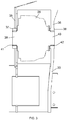
- Figure 3 shows a section view, indicating how the gearbox 26 may be mounted relative to the cradle frame 20.
- the gearbox housing 28 is held between two sidewalls 35 and 36 of a support bracket that is fixedly attached or uniform with the cradle frame 20.
- the sidewalls comprise bushings 37 and 38 and the gearbox housing is provided with machined cylindrical surfaces 39 and 40 which match with the bushings, preferably with bearings 41 and 42 such as sliding bearings or roller bearings between the bushings and the cylindrical surfaces.
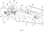
- a mechanical link 45 is furthermore provided adjacent the extendable drive axle 24, between the feeder housing 11 and the transverse gearbox housing 28.
- the mechanical link 45 comprises an extendable shaft 46, i.e. a shaft of variable length having a first and second part which can slide relative to each other.
- the shaft 46 is connected through a ball joint 47 to a support bracket 48 that is bolted or welded to the feeder housing 11.
- the shaft 46 is connected to the gearbox housing 28 through a pivot 49 defined by a pivot axis oriented upward and transverse relative to the gearbox's input and output axles 29 and 30.
- the pivot 49 is mounted at the end of a support plate 50 fixedly attached to the gearbox housing.
- the sidewalls 36 and 37 between which the gearbox housing is rotatably mounted are equally visible in Figure 2 .
- the degrees of freedom provided to the mechanical link 45 by the extendable shaft 46, the ball joint 47 and the pivot 49, enable the mechanical link's function of maintaining the transverse gearbox 26 in proper alignment with the drive axle 24, regardless of the position of the cradle frame 20 relative to the feeder housing 11.
- the gearbox 26 is mounted on the cradle frame, no complex rotational connection is required between the header drive axle and the output axle of the gearbox.
- the mechanism thereby allows a significant range of header movements relative to the feeder, such as the forward and backward tilting movement and the sideways flotation, while the rotational coupling between the driveline and the header drive axle remains assured.
- the rotation axis of the gearbox housing 28 in the embodiment of Figures 2 and 4 coincides with the rotation axis of the output axle 30 of the gearbox 26.
- This header drive axle may be directly coupled to the output axle 30 through a suitable coupling mechanism.
- the invention is however not limited to this particular embodiment and the rotation axis of the gearbox housing 28 may be separate from the rotation axis of the output axle 30. This may be required or advantageous for allowing a particular degree of movement to the header relative to the feeder. It will however require a more complex coupling mechanism between the header drive axle and the gearbox 26.
- the transverse gearbox comprises a split housing, one portion of which is fixedly attached to the cradle frame 20, while the other portion is rotatable relative to the fixed portion and to the cradle frame.
- the fixed portion comprises a large output bevel gear coupled to the gearbox's output axle 30, while the rotatable portion comprises an input pinion gear coupled to the gearbox' input axle.
- the rotatable portion is rotatable about the output axis of the gearbox.
- the mechanical link is mounted between the rotatable gearbox housing portion and the feeder housing, in the same manner as described in relation to the embodiment of Figure 2 . Provided that adequate sealing is produced between the gearbox housing portions, this setup is fully equivalent to the embodiments described above.
- a single header drive axle is present on one side of the combine, as shown in the drawings, i.e. a single rotatable transverse gearbox 26 is required.
- the mechanism of the invention may however also be provided on both sides of the combine harvester, when the header comprises drive axles on both sides.
Landscapes
- Life Sciences & Earth Sciences (AREA)
- Environmental Sciences (AREA)
- Harvester Elements (AREA)
Abstract
Description
- The present invention is related to combine harvesters, in particular to the driveline for actuating the operation of the header of the combine.
- Agricultural combine harvesters are machines designed for harvesting and processing crops such as wheat or corn. Crops are cut from the field on a wide area by the header mounted at the front of the combine. By an auger or a belt system included in the header, the harvested material is brought to a central area of the header, and from there it is transported by the feeder to a threshing mechanism comprising laterally or longitudinally mounted threshing rotors and further to the cleaning section comprising a number of sieves where grains are separated from any remaining crop residue.
- The header is suspended on a cradle frame attached at the front of the feeder. In modern combines, this cradle frame is movable with respect to the feeder housing in order to allow a freedom of movement to the header during the harvesting operation. The cradle frame is usually configured so that a pivoting motion is allowed both around a horizontal axis that is perpendicular to the longitudinal axis of the harvester and about a second axis parallel to said longitudinal axis. The first degree of freedom allows the cradle and thereby the header to be tilted forward or backward relative to the feeder housing, while the second allows a lateral flotation of the header.
- A known way of operationally coupling the header to the combine utilises a driveline from the combine's power source to the header which passes along one side of the feeder where it is coupled to a drive axle on the header through a transverse gearbox, configured to transfer the rotation of the driveline oriented in the forward direction of the combine to a rotation of the header drive axle oriented transversally to said forward direction. In presently known systems of this type, the transverse gearbox is bolted to the side of the feeder, which requires a complex rotational connection between the gearbox and the header's drive axle in order to allow the header to undergo the above-described movements relative to the feeder. The angular range of said rotational connection however limits the amplitude of the header's movements, especially when both degrees of freedom, tilting and lateral flotation, are simultaneously available. As combines increase in size and as the requirements in terms of the header movement increase, the existing mechanism is therefore no longer sustainable.
- The present invention is related to a combine harvester in accordance with the appended claims. In a harvester according to the invention, a forward-directed driveline of the combine is coupled to a transversely oriented header drive axle through a transverse gearbox that is mounted on the cradle frame. In addition, the housing of the gearbox or at least the portion of the housing comprising the input axle of the gearbox is rotatably arranged relative to the cradle frame, about a rotation axis oriented transversely to the combine's forward direction. A mechanical link is furthermore provided between the rotatable gearbox housing or rotatable housing portion and the feeder housing, configured to control the orientation of the input axle of the transverse gearbox, so as to maintain the alignment of said input axle relative to the driveline of the combine. This mechanism is advantageous in that no universal joint is required between the output axle of the gearbox and the header drive axle, thereby increasing the freedom of movement of the cradle frame and thereby of the header, relative to the feeder housing.
-
-
Figure 1 is a schematic side view of a combine header as known in the art, indicating the position of the header and the feeder at the front of the machine. -
Figure 2 shows a header drive mechanism in a combine harvester according to a preferred embodiment of the invention. -
Figure 3 is a section view of a rotatable transverse gearbox in a combine harvester according to an embodiment of the invention. -
Figure 4 more detailed view of the mechanism ofFigure 2 . - Preferred embodiments will now be described with reference to the drawings. The detailed description is not limiting the scope of the invention, which is defined only by the appended claims. The terms 'front' and 'back' or 'rear' are referenced to the front and back side of the combine harvester. The 'forward direction' of the combine harvester refers not to a single geometrical axis but to the general direction from the rear of the vehicle to the front.
-
Figure 1 is a schematic image of acombine harvester 10 as known today, comprising aheader 1 mounted at the front of the combine. The header comprisesknives 2 maintained at a given height above ground level while the combine moves through a field of crops that are to be harvested. A rotatingreel 3 guides the crops towards the knives. Cut crops are transported from both lateral sides of the header towards a central area by anauger 4. Themain body 5 of the combine is supported by front andrear wheels Figure 1 . From the central area of theheader 1, crops are transported into themain body 5 of the combine by afeeder 8. Thefeeder 8 is inclined upwards from theheader 1 towards themain body 5 and comprises movingbelts 9 inside ahousing 11. The belts transport the crops upwards, from aninlet section 12 of the feeder to anoutlet section 13. At the front of the feeder, acradle frame 20 is attached, onto which theheader 1 is mounted and secured. As described in the introductory portion, thecradle frame 20 is movable relative to thefeeder 8. The cradle frame may at least be pivotable about a tilting axis for tilting the header forward or backward, and preferably also about a longitudinal axis for allowing the header to undergo a lateral flotation. These movements are controlled by actuators (not shown) mounted between thefeeder housing 8 and thecradle frame 20. The rotation of thereel 3 and theauger 4 is driven by a header drive axle which is itself rotatably coupled to the driveline of the combine as described in the introductory portion. -
Figure 2 shows a detail of the left-hand side of thefeeder housing 11, in a combine harvester according to a preferred embodiment of the invention. Theheader frame 14 and thecradle frame 20 are visible in the drawing. Theheader frame 14 is the portion of the header that is directly attached to thecradle frame 20. Thecradle frame 20 is mounted on afront structure 15 of the feeder. Agearbox 23 is fixedly attached, for example bolted to the sidewall of thefeeder housing 11, in the vicinity of the feeder's outlet section. Adrive axle 24 that is extendable in length is coupled to thefixed gearbox 23 by a firstuniversal joint 25. At its opposite end, thedrive axle 24 is coupled to atransverse gearbox 26 by a seconduniversal joint 27. Thetransverse gearbox 26 comprises agearbox housing 28, aninput axle 29 coupled to the seconduniversal joint 27 and anoutput axle 30 oriented transversely, preferably orthogonally, with respect to theinput axle 29. Thetransverse gearbox 26 as such may operate according to known principles and techniques. Inside thegearbox housing 28 is a gear mechanism operating in the presence of a lubricant. The gear mechanism may comprise a larger bevel gear coupled to theoutput axle 30 and a smaller bevel gear (pinion gear) coupled to theinput axle 29. The position of the input andoutput axles 29/30 is fixed relative to thegearbox housing 28. - In the terminology of the appended claims, the
drive axle 24,universal joints fixed gearbox 23 are part of the driveline configured to drive the rotation of the header's drive axle (not shown inFigure 2 ) when said header drive axle is coupled to theoutput axle 30 of thetransverse gearbox 26. The driveline may further comprise, to the opposite side of thefixed gearbox 23, a plurality of axles interconnected by universal joints, as well as further gearboxes, and is rotatably driven by a power source of the combine, usually a hydraulic motor. - A characteristic feature of the embodiment shown in
Figure 2 is that the gearbox housing 28 of thetransverse gearbox 26 is rotatably mounted on thecradle frame 20. Thehousing 28 is rotatable relative to thecradle frame 11, about an axis that is transversely oriented with respect to thedrive axle 24. Preferably but not necessarily, the rotation axis of thegearbox housing 28 coincides with the axis of the gearbox'soutput axle 30.Figure 3 shows a section view, indicating how thegearbox 26 may be mounted relative to thecradle frame 20. Thegearbox housing 28 is held between twosidewalls cradle frame 20. The sidewalls comprisebushings cylindrical surfaces bearings - In order to maintain the
gearbox 26 in a position where itsinput axle 29 faces thefixed gearbox 23, amechanical link 45 is furthermore provided adjacent theextendable drive axle 24, between thefeeder housing 11 and thetransverse gearbox housing 28. As seen inFigure 4 , themechanical link 45 comprises anextendable shaft 46, i.e. a shaft of variable length having a first and second part which can slide relative to each other. At one end, theshaft 46 is connected through a ball joint 47 to asupport bracket 48 that is bolted or welded to thefeeder housing 11. At the opposite end, theshaft 46 is connected to thegearbox housing 28 through apivot 49 defined by a pivot axis oriented upward and transverse relative to the gearbox's input andoutput axles pivot 49 is mounted at the end of asupport plate 50 fixedly attached to the gearbox housing. Thesidewalls Figure 2 . - The degrees of freedom provided to the
mechanical link 45 by theextendable shaft 46, the ball joint 47 and thepivot 49, enable the mechanical link's function of maintaining thetransverse gearbox 26 in proper alignment with thedrive axle 24, regardless of the position of thecradle frame 20 relative to thefeeder housing 11. As thegearbox 26 is mounted on the cradle frame, no complex rotational connection is required between the header drive axle and the output axle of the gearbox. The mechanism thereby allows a significant range of header movements relative to the feeder, such as the forward and backward tilting movement and the sideways flotation, while the rotational coupling between the driveline and the header drive axle remains assured. - The above-described embodiment is not limiting the scope of the present invention, and variations to certain features are possible without departing from the scope. The way in which the mechanical link is brought into practice may differ from the one shown, and the functionality of this link is sufficient to allow the skilled person to devise alternative realisations of the link, which may also depend on the degrees of freedom of movement of the header relative to the feeder. The embodiment shown in
Figure 2 allows forward and backward tilting as well as floatation of the header, but even in this design, some elements may be replaced by equivalent means. For example, thepivot 29 could be replaced by a flexible coupling between the end of theextendable shaft 46 and thegearbox housing 28. The flexible coupling may for example comprise a resilient element with sufficient flexibility for allowing the header movement, and with sufficient stiffness for controlling the position of thetransverse gearbox 26. - As stated, the rotation axis of the
gearbox housing 28 in the embodiment ofFigures 2 and4 coincides with the rotation axis of theoutput axle 30 of thegearbox 26. This is an advantageous embodiment because it facilitates the coupling of the header drive axle to thegearbox 26. This header drive axle may be directly coupled to theoutput axle 30 through a suitable coupling mechanism. The invention is however not limited to this particular embodiment and the rotation axis of thegearbox housing 28 may be separate from the rotation axis of theoutput axle 30. This may be required or advantageous for allowing a particular degree of movement to the header relative to the feeder. It will however require a more complex coupling mechanism between the header drive axle and thegearbox 26. - According to an alternative embodiment, the transverse gearbox comprises a split housing, one portion of which is fixedly attached to the
cradle frame 20, while the other portion is rotatable relative to the fixed portion and to the cradle frame. According to an embodiment, the fixed portion comprises a large output bevel gear coupled to the gearbox'soutput axle 30, while the rotatable portion comprises an input pinion gear coupled to the gearbox' input axle. The rotatable portion is rotatable about the output axis of the gearbox. The mechanical link is mounted between the rotatable gearbox housing portion and the feeder housing, in the same manner as described in relation to the embodiment ofFigure 2 . Provided that adequate sealing is produced between the gearbox housing portions, this setup is fully equivalent to the embodiments described above. - According to an embodiment, a single header drive axle is present on one side of the combine, as shown in the drawings, i.e. a single rotatable
transverse gearbox 26 is required. The mechanism of the invention may however also be provided on both sides of the combine harvester, when the header comprises drive axles on both sides.
Claims (7)
- A combine harvester (10) comprising :• a feeder (8) at the front of the harvester, the feeder comprising a housing (11), an input section (12) and an output section (13),• a cradle frame (20) that is movably attached at the front of the feeder (8), wherein the cradle frame is configured to receive a header (1) comprising a header drive axle oriented transversely to the forward direction of the harvester (10) when the header (1) is coupled to the feeder (8),• a driveline, at least a portion of which is running alongside the feeder housing (11),• a transverse gearbox (26) for transferring a rotation of the driveline to a rotation of the header drive axle, the gearbox comprising a gear mechanism mounted in a gearbox housing (28), a input axle (29) coupled to the driveline and an output axle (30) configured to be coupled to the header drive axle,characterised in that:• at least a portion of the housing (28) of the transverse gearbox (26) is rotatably mounted on the cradle frame (20), the housing or housing portion being rotatable about an axis that is oriented transversely relative to the driveline,• a mechanical link (45) is coupled between the feeder housing (11) and the rotatable gearbox housing (28) or housing portion, wherein the mechanical link (45) is configured to control the orientation of the input axle (29) of the gearbox, regardless of the position of the cradle frame (20) relative to the feeder (8).
- The combine header according to claim 1, wherein the mechanical link (45) comprises a shaft of extendable length (46), a ball joint (47) fixed to the feeder housing (11) and a flexible coupling (49), wherein the shaft (46) is connected at one side to the ball joint (47) and connected at the other side to the flexible coupling (49) mounted between the shaft and the rotatable gearbox housing (28) or housing portion.
- The combine header according to claim 2, wherein the flexible coupling comprises a pivot (49) defined by a pivot axis that is transversely oriented with respect to both the input axle (29) and the output axle (30) of the transverse gearbox (26).
- The combine header according to any one of the preceding claims, wherein the rotation axis of the housing (28) or housing portion of the transverse gearbox (26) relative to the cradle frame (20) coincides with the rotation axis of the output axle (30) of said gearbox (26).
- The combine header according to any one of the preceding claims, wherein the driveline comprises a gearbox (23) that is fixedly attached to the feeder housing, and a drive axle of variable length (24) coupled at one end to said fixed gearbox (23) by a first universal joint (25) and at the opposite end to the input axle (29) of the transverse gearbox (26), by a second universal joint (27).
- The combine header according to any one of the preceding claims, wherein the housing (28) of the transverse gearbox (26) is rotatable as a whole relative to the cradle frame (20), and wherein said housing (28) is provided with cylindrical surfaces (39,40) mounted rotatably inside bushings (37,38) provided in a pair of sidewalls (35,36) of a support bracket that is fixedly attached to or uniform with the cradle frame (20), with a set of bearings (41,42) mounted between the bushings (37,38) and the cylindrical surfaces (39,40).
- The combine header according to any one of claims 1 to 5, wherein the transverse gearbox comprises a split housing, comprising a first housing portion that is fixedly attached to the cradle frame and a second housing portion that is rotatable relative to the first portion, the second housing portion comprising the input axle of the transverse gearbox.
Priority Applications (5)
| Application Number | Priority Date | Filing Date | Title |
|---|---|---|---|
| EP18213672.1A EP3669633B1 (en) | 2018-12-18 | 2018-12-18 | A header drive mechanism for a combine harvester |
| US17/415,112 US12108705B2 (en) | 2018-12-18 | 2019-12-17 | Header drive mechanism for a combine harvester |
| CN201980088683.1A CN113301795B (en) | 2018-12-18 | 2019-12-17 | Head drive for combine harvesters |
| BR112021011830-6A BR112021011830B1 (en) | 2018-12-18 | 2019-12-17 | Combine harvester with platform drive mechanism |
| PCT/EP2019/085656 WO2020127269A1 (en) | 2018-12-18 | 2019-12-17 | A header drive mechanism for a combine harvester |
Applications Claiming Priority (1)
| Application Number | Priority Date | Filing Date | Title |
|---|---|---|---|
| EP18213672.1A EP3669633B1 (en) | 2018-12-18 | 2018-12-18 | A header drive mechanism for a combine harvester |
Publications (2)
| Publication Number | Publication Date |
|---|---|
| EP3669633A1 true EP3669633A1 (en) | 2020-06-24 |
| EP3669633B1 EP3669633B1 (en) | 2022-02-09 |
Family
ID=64745959
Family Applications (1)
| Application Number | Title | Priority Date | Filing Date |
|---|---|---|---|
| EP18213672.1A Active EP3669633B1 (en) | 2018-12-18 | 2018-12-18 | A header drive mechanism for a combine harvester |
Country Status (4)
| Country | Link |
|---|---|
| US (1) | US12108705B2 (en) |
| EP (1) | EP3669633B1 (en) |
| CN (1) | CN113301795B (en) |
| WO (1) | WO2020127269A1 (en) |
Cited By (1)
| Publication number | Priority date | Publication date | Assignee | Title |
|---|---|---|---|---|
| EP4215036A1 (en) * | 2022-01-20 | 2023-07-26 | CNH Industrial Belgium N.V. | A driveline for the reciprocating knives of a combine header |
Families Citing this family (1)
| Publication number | Priority date | Publication date | Assignee | Title |
|---|---|---|---|---|
| EP4710749A1 (en) * | 2024-09-17 | 2026-03-18 | Deere & Company | Drive assembly for driving a harvester head by a forage harvester |
Citations (3)
| Publication number | Priority date | Publication date | Assignee | Title |
|---|---|---|---|---|
| EP1440617A1 (en) * | 2003-01-24 | 2004-07-28 | Maschinenfabrik Kemper GmbH & Co. KG | Drive system for a harvester head |
| WO2011095525A1 (en) * | 2010-02-02 | 2011-08-11 | Cnh Belgium N.V. | Agricultural harvester with automatic header coupling |
| US20160044870A1 (en) * | 2014-08-14 | 2016-02-18 | Dean Mayerle | Drive System for the Straw Chopper of a Combine Harvester |
Family Cites Families (17)
| Publication number | Priority date | Publication date | Assignee | Title |
|---|---|---|---|---|
| US4174603A (en) * | 1978-03-31 | 1979-11-20 | Sperry Rand Corporation | Telescoping lateral limit link |
| US4227366A (en) * | 1979-08-06 | 1980-10-14 | Sperry Corporation | Corn header drive system |
| DE3431549C1 (en) | 1984-08-28 | 1986-03-06 | O & K Orenstein & Koppel Ag, 1000 Berlin | Protective device for cardan shafts on work vehicles with a foldable vehicle frame |
| US5665074A (en) | 1995-09-28 | 1997-09-09 | Liebel Flarsheim Company | Limited backflow reflux valve |
| DE10018211A1 (en) * | 2000-04-12 | 2001-11-22 | Claas Selbstfahr Erntemasch | Agricultural harvester |
| US6705067B2 (en) | 2002-07-16 | 2004-03-16 | Case Corporation | Feed conveyor/rock trap and header drive for an agricultural combine |
| US7552578B2 (en) | 2006-07-10 | 2009-06-30 | Cnh America Llc | Method and device for automatically coupling a combine feeder interface and a combine header |
| DE202007015176U1 (en) | 2007-10-31 | 2009-03-12 | Alois Pöttinger Maschinenfabrik Gmbh | agricultural machinery |
| US9913430B2 (en) * | 2014-09-15 | 2018-03-13 | Cnh Industrial America Llc | Power takeoff drive assembly for a corn header of an agricultural harvester |
| BE1022551B1 (en) * | 2014-11-27 | 2016-05-31 | Cnh Industrial Belgium Nv | HARVESTER FOR USE IN AGRICULTURE |
| GB201510914D0 (en) * | 2015-06-22 | 2015-08-05 | Agco Do Brasil Comércio E Indústria Ltda | Automated system for coupling a harvester header drivetrain |
| US10125848B2 (en) * | 2016-07-19 | 2018-11-13 | Deere & Company | Variator for work vehicle drivetrain |
| CN106717492A (en) * | 2016-11-15 | 2017-05-31 | 金华职业技术学院 | A kind of ceding of Taiwan swinging angle control mechanism in cereal combining equipment |
| US10165726B2 (en) * | 2016-12-23 | 2019-01-01 | Cnh Industrial America Llc | Agricultural header with multiple knife drives |
| US10568262B2 (en) * | 2017-09-28 | 2020-02-25 | Cnh Industrial America Llc | Actively synchronized dual reciprocating-knife cutter bar |
| DE102021119897A1 (en) * | 2021-07-30 | 2023-02-02 | Claas Selbstfahrende Erntemaschinen Gmbh | Agricultural machine with anti-vibration front attachment |
| EP4268566A1 (en) * | 2022-04-29 | 2023-11-01 | CNH Industrial Belgium N.V. | A system and method for monitoring the condition of the cutting knives of a combine header |
-
2018
- 2018-12-18 EP EP18213672.1A patent/EP3669633B1/en active Active
-
2019
- 2019-12-17 WO PCT/EP2019/085656 patent/WO2020127269A1/en not_active Ceased
- 2019-12-17 US US17/415,112 patent/US12108705B2/en active Active
- 2019-12-17 CN CN201980088683.1A patent/CN113301795B/en active Active
Patent Citations (3)
| Publication number | Priority date | Publication date | Assignee | Title |
|---|---|---|---|---|
| EP1440617A1 (en) * | 2003-01-24 | 2004-07-28 | Maschinenfabrik Kemper GmbH & Co. KG | Drive system for a harvester head |
| WO2011095525A1 (en) * | 2010-02-02 | 2011-08-11 | Cnh Belgium N.V. | Agricultural harvester with automatic header coupling |
| US20160044870A1 (en) * | 2014-08-14 | 2016-02-18 | Dean Mayerle | Drive System for the Straw Chopper of a Combine Harvester |
Cited By (2)
| Publication number | Priority date | Publication date | Assignee | Title |
|---|---|---|---|---|
| EP4215036A1 (en) * | 2022-01-20 | 2023-07-26 | CNH Industrial Belgium N.V. | A driveline for the reciprocating knives of a combine header |
| US12550815B2 (en) | 2022-01-20 | 2026-02-17 | Cnh Industrial America Llc | Driveline for the reciprocating knives of a combine header |
Also Published As
| Publication number | Publication date |
|---|---|
| US20220053694A1 (en) | 2022-02-24 |
| EP3669633B1 (en) | 2022-02-09 |
| WO2020127269A1 (en) | 2020-06-25 |
| US12108705B2 (en) | 2024-10-08 |
| CN113301795B (en) | 2023-01-17 |
| CN113301795A (en) | 2021-08-24 |
| BR112021011830A2 (en) | 2021-08-31 |
Similar Documents
| Publication | Publication Date | Title |
|---|---|---|
| EP2420128B1 (en) | Flexible draper belt drive for an agricultural harvesting machine | |
| US10653069B2 (en) | Residue handling system for an agricultural harvester | |
| CA2455661C (en) | Drive train for a header of a harvesting machine | |
| US7555884B2 (en) | Self-propelled harvesting machine with a front harvesting attachment that can be pivoted about a vertical axis | |
| EP3090615B1 (en) | Feeder assembly for an agricultural harvester header | |
| EP3914063B1 (en) | Reel assembly of an agricultural header | |
| US7043891B2 (en) | Crop filter auger for a crop intake assembly | |
| EP2420127B1 (en) | Spring assisted translating draper belt drive rollers for an agricultural harvesting machine | |
| US11497166B2 (en) | Belt drive for driving the header of a combine harvester | |
| US12108705B2 (en) | Header drive mechanism for a combine harvester | |
| US12610889B2 (en) | Harvesting attachment with height-adjustable cross-feeding auger | |
| US9072220B2 (en) | Agricultural harvester drive line | |
| CA3002835C (en) | Draper header for attachment to a harvesting machine | |
| US20250151659A1 (en) | Power transmission applicable in a combine harvester | |
| US20220046858A1 (en) | A header driveline coupling mechanism for a combine harvester | |
| EP4555852A1 (en) | Feed roll drive for agricultural harvester thresher | |
| CN119183800A (en) | Harvester transmission system and harvester | |
| US3245208A (en) | Pull-type combine | |
| BR112021011830B1 (en) | Combine harvester with platform drive mechanism | |
| EP4052558B1 (en) | Swing-out spreader for agricultural combines | |
| CA3126093C (en) | Reel assembly of an agricultural header | |
| EP3756438B1 (en) | Combine header comprising a centrally extending header floor | |
| JPH10276547A (en) | Combine harvesting frame support device |
Legal Events
| Date | Code | Title | Description |
|---|---|---|---|
| PUAI | Public reference made under article 153(3) epc to a published international application that has entered the european phase |
Free format text: ORIGINAL CODE: 0009012 |
|
| STAA | Information on the status of an ep patent application or granted ep patent |
Free format text: STATUS: THE APPLICATION HAS BEEN PUBLISHED |
|
| AK | Designated contracting states |
Kind code of ref document: A1 Designated state(s): AL AT BE BG CH CY CZ DE DK EE ES FI FR GB GR HR HU IE IS IT LI LT LU LV MC MK MT NL NO PL PT RO RS SE SI SK SM TR |
|
| AX | Request for extension of the european patent |
Extension state: BA ME |
|
| STAA | Information on the status of an ep patent application or granted ep patent |
Free format text: STATUS: REQUEST FOR EXAMINATION WAS MADE |
|
| 17P | Request for examination filed |
Effective date: 20210111 |
|
| RBV | Designated contracting states (corrected) |
Designated state(s): AL AT BE BG CH CY CZ DE DK EE ES FI FR GB GR HR HU IE IS IT LI LT LU LV MC MK MT NL NO PL PT RO RS SE SI SK SM TR |
|
| GRAP | Despatch of communication of intention to grant a patent |
Free format text: ORIGINAL CODE: EPIDOSNIGR1 |
|
| STAA | Information on the status of an ep patent application or granted ep patent |
Free format text: STATUS: GRANT OF PATENT IS INTENDED |
|
| INTG | Intention to grant announced |
Effective date: 20210310 |
|
| GRAJ | Information related to disapproval of communication of intention to grant by the applicant or resumption of examination proceedings by the epo deleted |
Free format text: ORIGINAL CODE: EPIDOSDIGR1 |
|
| STAA | Information on the status of an ep patent application or granted ep patent |
Free format text: STATUS: REQUEST FOR EXAMINATION WAS MADE |
|
| GRAP | Despatch of communication of intention to grant a patent |
Free format text: ORIGINAL CODE: EPIDOSNIGR1 |
|
| STAA | Information on the status of an ep patent application or granted ep patent |
Free format text: STATUS: GRANT OF PATENT IS INTENDED |
|
| INTC | Intention to grant announced (deleted) | ||
| INTG | Intention to grant announced |
Effective date: 20210721 |
|
| GRAS | Grant fee paid |
Free format text: ORIGINAL CODE: EPIDOSNIGR3 |
|
| GRAA | (expected) grant |
Free format text: ORIGINAL CODE: 0009210 |
|
| STAA | Information on the status of an ep patent application or granted ep patent |
Free format text: STATUS: THE PATENT HAS BEEN GRANTED |
|
| AK | Designated contracting states |
Kind code of ref document: B1 Designated state(s): AL AT BE BG CH CY CZ DE DK EE ES FI FR GB GR HR HU IE IS IT LI LT LU LV MC MK MT NL NO PL PT RO RS SE SI SK SM TR |
|
| REG | Reference to a national code |
Ref country code: GB Ref legal event code: FG4D |
|
| REG | Reference to a national code |
Ref country code: CH Ref legal event code: EP Ref country code: AT Ref legal event code: REF Ref document number: 1466933 Country of ref document: AT Kind code of ref document: T Effective date: 20220215 |
|
| REG | Reference to a national code |
Ref country code: IE Ref legal event code: FG4D |
|
| REG | Reference to a national code |
Ref country code: DE Ref legal event code: R096 Ref document number: 602018030540 Country of ref document: DE |
|
| REG | Reference to a national code |
Ref country code: LT Ref legal event code: MG9D |
|
| REG | Reference to a national code |
Ref country code: NL Ref legal event code: MP Effective date: 20220209 |
|
| REG | Reference to a national code |
Ref country code: AT Ref legal event code: MK05 Ref document number: 1466933 Country of ref document: AT Kind code of ref document: T Effective date: 20220209 |
|
| PG25 | Lapsed in a contracting state [announced via postgrant information from national office to epo] |
Ref country code: SE Free format text: LAPSE BECAUSE OF FAILURE TO SUBMIT A TRANSLATION OF THE DESCRIPTION OR TO PAY THE FEE WITHIN THE PRESCRIBED TIME-LIMIT Effective date: 20220209 Ref country code: RS Free format text: LAPSE BECAUSE OF FAILURE TO SUBMIT A TRANSLATION OF THE DESCRIPTION OR TO PAY THE FEE WITHIN THE PRESCRIBED TIME-LIMIT Effective date: 20220209 Ref country code: PT Free format text: LAPSE BECAUSE OF FAILURE TO SUBMIT A TRANSLATION OF THE DESCRIPTION OR TO PAY THE FEE WITHIN THE PRESCRIBED TIME-LIMIT Effective date: 20220609 Ref country code: NO Free format text: LAPSE BECAUSE OF FAILURE TO SUBMIT A TRANSLATION OF THE DESCRIPTION OR TO PAY THE FEE WITHIN THE PRESCRIBED TIME-LIMIT Effective date: 20220509 Ref country code: NL Free format text: LAPSE BECAUSE OF FAILURE TO SUBMIT A TRANSLATION OF THE DESCRIPTION OR TO PAY THE FEE WITHIN THE PRESCRIBED TIME-LIMIT Effective date: 20220209 Ref country code: LT Free format text: LAPSE BECAUSE OF FAILURE TO SUBMIT A TRANSLATION OF THE DESCRIPTION OR TO PAY THE FEE WITHIN THE PRESCRIBED TIME-LIMIT Effective date: 20220209 Ref country code: HR Free format text: LAPSE BECAUSE OF FAILURE TO SUBMIT A TRANSLATION OF THE DESCRIPTION OR TO PAY THE FEE WITHIN THE PRESCRIBED TIME-LIMIT Effective date: 20220209 Ref country code: ES Free format text: LAPSE BECAUSE OF FAILURE TO SUBMIT A TRANSLATION OF THE DESCRIPTION OR TO PAY THE FEE WITHIN THE PRESCRIBED TIME-LIMIT Effective date: 20220209 Ref country code: BG Free format text: LAPSE BECAUSE OF FAILURE TO SUBMIT A TRANSLATION OF THE DESCRIPTION OR TO PAY THE FEE WITHIN THE PRESCRIBED TIME-LIMIT Effective date: 20220509 |
|
| PG25 | Lapsed in a contracting state [announced via postgrant information from national office to epo] |
Ref country code: PL Free format text: LAPSE BECAUSE OF FAILURE TO SUBMIT A TRANSLATION OF THE DESCRIPTION OR TO PAY THE FEE WITHIN THE PRESCRIBED TIME-LIMIT Effective date: 20220209 Ref country code: LV Free format text: LAPSE BECAUSE OF FAILURE TO SUBMIT A TRANSLATION OF THE DESCRIPTION OR TO PAY THE FEE WITHIN THE PRESCRIBED TIME-LIMIT Effective date: 20220209 Ref country code: GR Free format text: LAPSE BECAUSE OF FAILURE TO SUBMIT A TRANSLATION OF THE DESCRIPTION OR TO PAY THE FEE WITHIN THE PRESCRIBED TIME-LIMIT Effective date: 20220510 Ref country code: FI Free format text: LAPSE BECAUSE OF FAILURE TO SUBMIT A TRANSLATION OF THE DESCRIPTION OR TO PAY THE FEE WITHIN THE PRESCRIBED TIME-LIMIT Effective date: 20220209 Ref country code: AT Free format text: LAPSE BECAUSE OF FAILURE TO SUBMIT A TRANSLATION OF THE DESCRIPTION OR TO PAY THE FEE WITHIN THE PRESCRIBED TIME-LIMIT Effective date: 20220209 |
|
| PG25 | Lapsed in a contracting state [announced via postgrant information from national office to epo] |
Ref country code: IS Free format text: LAPSE BECAUSE OF FAILURE TO SUBMIT A TRANSLATION OF THE DESCRIPTION OR TO PAY THE FEE WITHIN THE PRESCRIBED TIME-LIMIT Effective date: 20220609 |
|
| PG25 | Lapsed in a contracting state [announced via postgrant information from national office to epo] |
Ref country code: SM Free format text: LAPSE BECAUSE OF FAILURE TO SUBMIT A TRANSLATION OF THE DESCRIPTION OR TO PAY THE FEE WITHIN THE PRESCRIBED TIME-LIMIT Effective date: 20220209 Ref country code: SK Free format text: LAPSE BECAUSE OF FAILURE TO SUBMIT A TRANSLATION OF THE DESCRIPTION OR TO PAY THE FEE WITHIN THE PRESCRIBED TIME-LIMIT Effective date: 20220209 Ref country code: RO Free format text: LAPSE BECAUSE OF FAILURE TO SUBMIT A TRANSLATION OF THE DESCRIPTION OR TO PAY THE FEE WITHIN THE PRESCRIBED TIME-LIMIT Effective date: 20220209 Ref country code: EE Free format text: LAPSE BECAUSE OF FAILURE TO SUBMIT A TRANSLATION OF THE DESCRIPTION OR TO PAY THE FEE WITHIN THE PRESCRIBED TIME-LIMIT Effective date: 20220209 Ref country code: DK Free format text: LAPSE BECAUSE OF FAILURE TO SUBMIT A TRANSLATION OF THE DESCRIPTION OR TO PAY THE FEE WITHIN THE PRESCRIBED TIME-LIMIT Effective date: 20220209 Ref country code: CZ Free format text: LAPSE BECAUSE OF FAILURE TO SUBMIT A TRANSLATION OF THE DESCRIPTION OR TO PAY THE FEE WITHIN THE PRESCRIBED TIME-LIMIT Effective date: 20220209 |
|
| REG | Reference to a national code |
Ref country code: DE Ref legal event code: R097 Ref document number: 602018030540 Country of ref document: DE |
|
| PG25 | Lapsed in a contracting state [announced via postgrant information from national office to epo] |
Ref country code: AL Free format text: LAPSE BECAUSE OF FAILURE TO SUBMIT A TRANSLATION OF THE DESCRIPTION OR TO PAY THE FEE WITHIN THE PRESCRIBED TIME-LIMIT Effective date: 20220209 |
|
| PLBE | No opposition filed within time limit |
Free format text: ORIGINAL CODE: 0009261 |
|
| STAA | Information on the status of an ep patent application or granted ep patent |
Free format text: STATUS: NO OPPOSITION FILED WITHIN TIME LIMIT |
|
| 26N | No opposition filed |
Effective date: 20221110 |
|
| PG25 | Lapsed in a contracting state [announced via postgrant information from national office to epo] |
Ref country code: SI Free format text: LAPSE BECAUSE OF FAILURE TO SUBMIT A TRANSLATION OF THE DESCRIPTION OR TO PAY THE FEE WITHIN THE PRESCRIBED TIME-LIMIT Effective date: 20220209 |
|
| REG | Reference to a national code |
Ref country code: CH Ref legal event code: PL |
|
| REG | Reference to a national code |
Ref country code: BE Ref legal event code: MM Effective date: 20221231 |
|
| PG25 | Lapsed in a contracting state [announced via postgrant information from national office to epo] |
Ref country code: LU Free format text: LAPSE BECAUSE OF NON-PAYMENT OF DUE FEES Effective date: 20221218 |
|
| PG25 | Lapsed in a contracting state [announced via postgrant information from national office to epo] |
Ref country code: LI Free format text: LAPSE BECAUSE OF NON-PAYMENT OF DUE FEES Effective date: 20221231 Ref country code: IE Free format text: LAPSE BECAUSE OF NON-PAYMENT OF DUE FEES Effective date: 20221218 Ref country code: CH Free format text: LAPSE BECAUSE OF NON-PAYMENT OF DUE FEES Effective date: 20221231 |
|
| PG25 | Lapsed in a contracting state [announced via postgrant information from national office to epo] |
Ref country code: BE Free format text: LAPSE BECAUSE OF NON-PAYMENT OF DUE FEES Effective date: 20221231 |
|
| PGFP | Annual fee paid to national office [announced via postgrant information from national office to epo] |
Ref country code: GB Payment date: 20231218 Year of fee payment: 6 |
|
| PG25 | Lapsed in a contracting state [announced via postgrant information from national office to epo] |
Ref country code: HU Free format text: LAPSE BECAUSE OF FAILURE TO SUBMIT A TRANSLATION OF THE DESCRIPTION OR TO PAY THE FEE WITHIN THE PRESCRIBED TIME-LIMIT; INVALID AB INITIO Effective date: 20181218 |
|
| PG25 | Lapsed in a contracting state [announced via postgrant information from national office to epo] |
Ref country code: CY Free format text: LAPSE BECAUSE OF FAILURE TO SUBMIT A TRANSLATION OF THE DESCRIPTION OR TO PAY THE FEE WITHIN THE PRESCRIBED TIME-LIMIT Effective date: 20220209 |
|
| PG25 | Lapsed in a contracting state [announced via postgrant information from national office to epo] |
Ref country code: MK Free format text: LAPSE BECAUSE OF FAILURE TO SUBMIT A TRANSLATION OF THE DESCRIPTION OR TO PAY THE FEE WITHIN THE PRESCRIBED TIME-LIMIT Effective date: 20220209 |
|
| PG25 | Lapsed in a contracting state [announced via postgrant information from national office to epo] |
Ref country code: MC Free format text: LAPSE BECAUSE OF FAILURE TO SUBMIT A TRANSLATION OF THE DESCRIPTION OR TO PAY THE FEE WITHIN THE PRESCRIBED TIME-LIMIT Effective date: 20220209 |
|
| PG25 | Lapsed in a contracting state [announced via postgrant information from national office to epo] |
Ref country code: MC Free format text: LAPSE BECAUSE OF FAILURE TO SUBMIT A TRANSLATION OF THE DESCRIPTION OR TO PAY THE FEE WITHIN THE PRESCRIBED TIME-LIMIT Effective date: 20220209 |
|
| PG25 | Lapsed in a contracting state [announced via postgrant information from national office to epo] |
Ref country code: MT Free format text: LAPSE BECAUSE OF FAILURE TO SUBMIT A TRANSLATION OF THE DESCRIPTION OR TO PAY THE FEE WITHIN THE PRESCRIBED TIME-LIMIT Effective date: 20220209 |
|
| GBPC | Gb: european patent ceased through non-payment of renewal fee |
Effective date: 20241218 |
|
| PG25 | Lapsed in a contracting state [announced via postgrant information from national office to epo] |
Ref country code: GB Free format text: LAPSE BECAUSE OF NON-PAYMENT OF DUE FEES Effective date: 20241218 |
|
| PG25 | Lapsed in a contracting state [announced via postgrant information from national office to epo] |
Ref country code: TR Free format text: LAPSE BECAUSE OF FAILURE TO SUBMIT A TRANSLATION OF THE DESCRIPTION OR TO PAY THE FEE WITHIN THE PRESCRIBED TIME-LIMIT Effective date: 20220209 |
|
| PGFP | Annual fee paid to national office [announced via postgrant information from national office to epo] |
Ref country code: IT Payment date: 20251218 Year of fee payment: 8 |
|
| PGFP | Annual fee paid to national office [announced via postgrant information from national office to epo] |
Ref country code: FR Payment date: 20251223 Year of fee payment: 8 |
|
| PGFP | Annual fee paid to national office [announced via postgrant information from national office to epo] |
Ref country code: DE Payment date: 20251229 Year of fee payment: 8 |