EP3669598B1 - Agrégation de multiples intervalles programmés, en une procédure harq - Google Patents
Agrégation de multiples intervalles programmés, en une procédure harq Download PDFInfo
- Publication number
- EP3669598B1 EP3669598B1 EP17921594.2A EP17921594A EP3669598B1 EP 3669598 B1 EP3669598 B1 EP 3669598B1 EP 17921594 A EP17921594 A EP 17921594A EP 3669598 B1 EP3669598 B1 EP 3669598B1
- Authority
- EP
- European Patent Office
- Prior art keywords
- slots
- carrier
- control signal
- scheduled
- slot
- Prior art date
- Legal status (The legal status is an assumption and is not a legal conclusion. Google has not performed a legal analysis and makes no representation as to the accuracy of the status listed.)
- Active
Links
- 238000000034 method Methods 0.000 title claims description 199
- 230000008569 process Effects 0.000 title claims description 154
- 230000002776 aggregation Effects 0.000 title claims description 50
- 238000004220 aggregation Methods 0.000 title claims description 50
- 230000005540 biological transmission Effects 0.000 claims description 18
- 230000004931 aggregating effect Effects 0.000 claims description 15
- 230000004044 response Effects 0.000 claims description 11
- 238000010586 diagram Methods 0.000 description 33
- 238000004891 communication Methods 0.000 description 28
- 238000003860 storage Methods 0.000 description 24
- 239000000969 carrier Substances 0.000 description 23
- 230000011664 signaling Effects 0.000 description 18
- 230000006870 function Effects 0.000 description 16
- 238000007726 management method Methods 0.000 description 6
- 230000000007 visual effect Effects 0.000 description 6
- 230000008901 benefit Effects 0.000 description 3
- 238000005516 engineering process Methods 0.000 description 3
- 230000003287 optical effect Effects 0.000 description 3
- 101150080315 SCS2 gene Proteins 0.000 description 2
- 101100072644 Saccharomyces cerevisiae (strain ATCC 204508 / S288c) INO2 gene Proteins 0.000 description 2
- 101100454372 Saccharomyces cerevisiae (strain ATCC 204508 / S288c) LCB2 gene Proteins 0.000 description 2
- 101100489624 Saccharomyces cerevisiae (strain ATCC 204508 / S288c) RTS1 gene Proteins 0.000 description 2
- 238000003491 array Methods 0.000 description 2
- 239000000463 material Substances 0.000 description 2
- 238000010295 mobile communication Methods 0.000 description 2
- 230000010363 phase shift Effects 0.000 description 2
- 239000004065 semiconductor Substances 0.000 description 2
- 230000003068 static effect Effects 0.000 description 2
- 230000001360 synchronised effect Effects 0.000 description 2
- 101000741965 Homo sapiens Inactive tyrosine-protein kinase PRAG1 Proteins 0.000 description 1
- 102100038659 Inactive tyrosine-protein kinase PRAG1 Human genes 0.000 description 1
- 241000234295 Musa Species 0.000 description 1
- 206010042135 Stomatitis necrotising Diseases 0.000 description 1
- 239000013256 coordination polymer Substances 0.000 description 1
- 125000004122 cyclic group Chemical group 0.000 description 1
- 230000001419 dependent effect Effects 0.000 description 1
- 238000001514 detection method Methods 0.000 description 1
- 230000000694 effects Effects 0.000 description 1
- 230000010354 integration Effects 0.000 description 1
- 230000007774 longterm Effects 0.000 description 1
- 238000004519 manufacturing process Methods 0.000 description 1
- 201000008585 noma Diseases 0.000 description 1
- 229920002939 poly(N,N-dimethylacrylamides) Polymers 0.000 description 1
- 229920001690 polydopamine Polymers 0.000 description 1
- 238000013468 resource allocation Methods 0.000 description 1
- 230000002441 reversible effect Effects 0.000 description 1
- 238000001228 spectrum Methods 0.000 description 1
Images


Classifications
-
- H—ELECTRICITY
- H04—ELECTRIC COMMUNICATION TECHNIQUE
- H04L—TRANSMISSION OF DIGITAL INFORMATION, e.g. TELEGRAPHIC COMMUNICATION
- H04L5/00—Arrangements affording multiple use of the transmission path
- H04L5/003—Arrangements for allocating sub-channels of the transmission path
- H04L5/0053—Allocation of signaling, i.e. of overhead other than pilot signals
- H04L5/0055—Physical resource allocation for ACK/NACK
-
- H—ELECTRICITY
- H04—ELECTRIC COMMUNICATION TECHNIQUE
- H04L—TRANSMISSION OF DIGITAL INFORMATION, e.g. TELEGRAPHIC COMMUNICATION
- H04L1/00—Arrangements for detecting or preventing errors in the information received
- H04L1/12—Arrangements for detecting or preventing errors in the information received by using return channel
- H04L1/16—Arrangements for detecting or preventing errors in the information received by using return channel in which the return channel carries supervisory signals, e.g. repetition request signals
- H04L1/18—Automatic repetition systems, e.g. Van Duuren systems
- H04L1/1822—Automatic repetition systems, e.g. Van Duuren systems involving configuration of automatic repeat request [ARQ] with parallel processes
-
- H—ELECTRICITY
- H04—ELECTRIC COMMUNICATION TECHNIQUE
- H04L—TRANSMISSION OF DIGITAL INFORMATION, e.g. TELEGRAPHIC COMMUNICATION
- H04L1/00—Arrangements for detecting or preventing errors in the information received
- H04L1/12—Arrangements for detecting or preventing errors in the information received by using return channel
- H04L1/16—Arrangements for detecting or preventing errors in the information received by using return channel in which the return channel carries supervisory signals, e.g. repetition request signals
- H04L1/18—Automatic repetition systems, e.g. Van Duuren systems
- H04L1/1829—Arrangements specially adapted for the receiver end
- H04L1/1854—Scheduling and prioritising arrangements
-
- H—ELECTRICITY
- H04—ELECTRIC COMMUNICATION TECHNIQUE
- H04L—TRANSMISSION OF DIGITAL INFORMATION, e.g. TELEGRAPHIC COMMUNICATION
- H04L1/00—Arrangements for detecting or preventing errors in the information received
- H04L1/12—Arrangements for detecting or preventing errors in the information received by using return channel
- H04L1/16—Arrangements for detecting or preventing errors in the information received by using return channel in which the return channel carries supervisory signals, e.g. repetition request signals
- H04L1/18—Automatic repetition systems, e.g. Van Duuren systems
- H04L1/1829—Arrangements specially adapted for the receiver end
- H04L1/1864—ARQ related signaling
-
- H—ELECTRICITY
- H04—ELECTRIC COMMUNICATION TECHNIQUE
- H04L—TRANSMISSION OF DIGITAL INFORMATION, e.g. TELEGRAPHIC COMMUNICATION
- H04L1/00—Arrangements for detecting or preventing errors in the information received
- H04L1/12—Arrangements for detecting or preventing errors in the information received by using return channel
- H04L1/16—Arrangements for detecting or preventing errors in the information received by using return channel in which the return channel carries supervisory signals, e.g. repetition request signals
- H04L1/18—Automatic repetition systems, e.g. Van Duuren systems
- H04L1/1867—Arrangements specially adapted for the transmitter end
- H04L1/1887—Scheduling and prioritising arrangements
-
- H—ELECTRICITY
- H04—ELECTRIC COMMUNICATION TECHNIQUE
- H04L—TRANSMISSION OF DIGITAL INFORMATION, e.g. TELEGRAPHIC COMMUNICATION
- H04L5/00—Arrangements affording multiple use of the transmission path
- H04L5/0001—Arrangements for dividing the transmission path
- H04L5/0003—Two-dimensional division
- H04L5/0005—Time-frequency
- H04L5/0007—Time-frequency the frequencies being orthogonal, e.g. OFDM(A), DMT
- H04L5/001—Time-frequency the frequencies being orthogonal, e.g. OFDM(A), DMT the frequencies being arranged in component carriers
-
- H—ELECTRICITY
- H04—ELECTRIC COMMUNICATION TECHNIQUE
- H04W—WIRELESS COMMUNICATION NETWORKS
- H04W72/00—Local resource management
- H04W72/20—Control channels or signalling for resource management
- H04W72/23—Control channels or signalling for resource management in the downlink direction of a wireless link, i.e. towards a terminal
-
- H—ELECTRICITY
- H04—ELECTRIC COMMUNICATION TECHNIQUE
- H04W—WIRELESS COMMUNICATION NETWORKS
- H04W72/00—Local resource management
- H04W72/12—Wireless traffic scheduling
- H04W72/1263—Mapping of traffic onto schedule, e.g. scheduled allocation or multiplexing of flows
- H04W72/1268—Mapping of traffic onto schedule, e.g. scheduled allocation or multiplexing of flows of uplink data flows
Definitions
- the subject matter disclosed herein relates generally to wireless communications and more particularly relates to apparatuses, methods, and systems for cross-carrier scheduling for CA with different numerologies on different carriers.
- downlink transport blocks are carried on the Physical Downlink Shared Channel (PDSCH).
- HARQ-ACK feedback bits corresponding to the PDSCH are transmitted either on the Physical Uplink Control Channel (PUCCH) or on the Physical Uplink Shared Channel (PUSCH).
- 5G networks support multiple transmission numerologies, such as 15, 30, and 60 kHz subcarrier spacing values for below 6 GHz and 60, 120 kHz subcarrier spacing values for above 6 GHz. To enable carrier aggregation scenarios across carrier frequencies below 6 GHz, across carrier frequencies above 6 GHz, and across low-high band, carrier combinations between 15, 30, 60, and 120 kHz need to be supported. In total, numerologies of 15, 30, 60, 120, 240, and 480 kHz are supported.
- DCI overhead may increase substantially.
- HARQ-ACK multiplexing and bundling describes various methods relating to HARQ-ACK feedback multiplexing and bundling.
- embodiments may be embodied as a system, apparatus, method, or program product. Accordingly, embodiments may take the form of an entirely hardware embodiment, an entirely software embodiment (including firmware, resident software, micro-code, etc.) or an embodiment combining software and hardware aspects.
- the disclosed embodiments may be implemented as a hardware circuit comprising custom very-large-scale integration ("VLSI") circuits or gate arrays, off-theshelf semiconductors such as logic chips, transistors, or other discrete components.
- VLSI very-large-scale integration
- the disclosed embodiments may also be implemented in programmable hardware devices such as field programmable gate arrays, programmable array logic, programmable logic devices, or the like.
- the disclosed embodiments may include one or more physical or logical blocks of executable code which may, for instance, be organized as an object, procedure, or function.
- embodiments may take the form of a program product embodied in one or more computer readable storage devices storing machine readable code, computer readable code, and/or program code, referred hereafter as code.
- the storage devices may be tangible, non-transitory, and/or non-transmission.
- the storage devices may not embody signals. In a certain embodiment, the storage devices only employ signals for accessing code.
- the computer readable medium may be a computer readable storage medium.
- the computer readable storage medium may be a storage device storing the code.
- the storage device may be, for example, but not limited to, an electronic, magnetic, optical, electromagnetic, infrared, holographic, micromechanical, or semiconductor system, apparatus, or device, or any suitable combination of the foregoing.
- a storage device More specific examples (a non-exhaustive list) of the storage device would include the following: an electrical connection having one or more wires, a portable computer diskette, a hard disk, a random-access memory (“RAM”), a read-only memory (“ROM”), an erasable programmable read-only memory (“EPROM” or Flash memory), a portable compact disc read-only memory (“CD-ROM”), an optical storage device, a magnetic storage device, or any suitable combination of the foregoing.
- a computer readable storage medium may be any tangible medium that can contain, or store a program for use by or in connection with an instruction execution system, apparatus, or device.
- the code may also be stored in a storage device that can direct a computer, other programmable data processing apparatus, or other devices to function in a particular manner, such that the instructions stored in the storage device produce an article of manufacture including instructions which implement the function/act specified in the schematic flowchart diagrams and/or schematic block diagrams.
- the code may also be loaded onto a computer, other programmable data processing apparatus, or other devices to cause a series of operational steps to be performed on the computer, other programmable apparatus, or other devices to produce a computer implemented process such that the code which execute on the computer or other programmable apparatus provide processes for implementing the functions/acts specified in the schematic flowchart diagrams and/or schematic block diagram.
- each block in the schematic flowchart diagrams and/or schematic block diagrams may represent a module, segment, or portion of code, which includes one or more executable instructions of the code for implementing the specified logical function(s).
- Figure 1 is a schematic block diagram illustrating one embodiment of a wireless communication system 100 for cross-carrier scheduling for CA with different numerologies on different carriers, according to embodiments of the disclosure.
- the wireless communication system 100 includes remote units 105, base units 110, and communication links 115. Even though a specific number of remote units 105, base units 110, and communication links 115 are depicted in Figure 1 , one of skill in the art will recognize that any number of remote units 105, base units 110, and communication links 115 may be included in the wireless communication system 100.
- the wireless communication system 100 is compliant with the 5G system specified in the 3GPP specifications. More generally, however, the wireless communication system 100 may implement some other open or proprietary communication network, for example, LTE-A or WiMAX, among other networks.
- LTE-A or WiMAX wireless communication system architecture or protocol.
- the remote units 105 may include computing devices, such as desktop computers, laptop computers, personal digital assistants ("PDAs"), tablet computers, smart phones, smart televisions (e.g., televisions connected to the Internet), smart appliances (e.g., appliances connected to the Internet), set-top boxes, game consoles, security systems (including security cameras), vehicle on-board computers, network devices (e.g., routers, switches, modems), or the like.
- the remote units 105 include wearable devices, such as smart watches, fitness bands, optical head-mounted displays, or the like.
- the remote units 105 may be referred to as subscriber units, mobiles, mobile stations, users, terminals, mobile terminals, fixed terminals, subscriber stations, user equipment ("UE"), user terminals, a device, or by other terminology used in the art.
- the remote units 105 may communicate directly with one or more of the base units 110 via uplink (“UL") and downlink (“DL") communication signals, for example a remote unit 105 may send data in a transmission block ("TB") to a base unit 110 via UL communication signals and receive data or control signals from the base unit via DL communication signals.
- UL and DL communication signals may be carried over the communication links 115.
- the base units 110 may be distributed over a geographic region.
- a base unit 110 may also be referred to as an access terminal, an access point, a base, a base station, a Node-B, an eNB, a gNB, a Home Node-B, a relay node, or by any other terminology used in the art.
- the base units 110 are generally part of a radio access network ("RAN") that may include one or more controllers communicably coupled to one or more corresponding base units 110.
- the RAN is generally communicably coupled to one or more core networks, which in turn may be coupled to other networks, like the Internet and public switched telephone networks, among other networks. These and other elements of radio access and core networks are not illustrated but are well known generally by those having ordinary skill in the art.
- the base units 110 connect to the mobile core network 130 via the RAN.
- the base units 110 may serve a number of remote units 105 within a serving area, for example, a cell or a cell sector via a wireless communication link.
- the base units 110 may communicate directly with one or more of the remote units 105 via communication signals.
- the base units 110 transmit downlink ("DL") communication signals to serve the remote units 105 in the time, frequency, and/or spatial domain.
- the DL communication signals may be carried over the communication links 115.
- the communication links 115 may be any suitable carrier in licensed or unlicensed radio spectrum.
- the communication links 115 facilitate communication between one or more of the remote units 105 and/or one or more of the base units 110.
- the mobile core network 130 is a 5G core (“5GC”) or the evolved packet core (“EPC”), which may be coupled to other data network 125, like the Internet and private data networks, among other data networks.
- Each mobile core network 130 belongs to a single public land mobile network (“PLMN”).
- PLMN public land mobile network
- the mobile core network 130 includes several network functions (“NFs”). As depicted, the mobile core network 130 includes an access and mobility management function (“AMF”) 135, a session management function (“SMF”) 140, and a user plane function (“UPF”) 145. Although a specific number of AMFs 135, SMFs 140, and UPFs 145 are depicted in Figure 1 , one of skill in the art will recognize that any number of AMFs 135, SMFs 140, and UPFs 145 may be included in the mobile core network 130.
- AMF access and mobility management function
- SMF session management function
- UPF user plane function
- the AMF 135 provides services such as UE registration, UE connection management, and UE mobility management.
- the SMF 140 manages the data sessions of the remote units 105, such as a PDU session.
- the UPF 145 provides user plane (e . g ., data) services to the remote units 105.
- a data connection between the remote unit 105 and a data network 125 is managed by a UPF 145.
- a base unit 110 may transmit, to a remote unit 105, downlink transmissions over multiple carriers or serving cells, referred as "carrier aggregation.”
- the remote unit 105 is configured with a set of two or more component carriers ("CCs").
- Each component carrier includes a plurality of subcarriers and has a subcarrier spacing value (also referred to as "numerology").
- a first component carrier has a smaller subcarrier spacing value than a second component carrier.
- multiple slots in the second component carrier correspond to one slot in the first component carrier.
- the base unit 110 uses the first carrier to schedule resources (e.g., slots) in the second carrier, referred to as "cross-carrier scheduling.” In some embodiments, the base unit 110 uses one slot in the first carrier to schedule multiple slots in the second carrier.
- the first carrier and second carrier are the same carrier, where the first carrier is a first portion of the carrier (e.g., carrying PDCCH) having a first numerology and the second carrier is a second portion of the same carrier (e.g., carrying PDSCH or PUSCH) having a second numerology greater than the first.
- the first carrier and second carrier are different carriers in the same frequency band.
- the first carrier and second carrier are the different carriers located in different frequency bands (e.g., one being in a low-frequency band with carrier frequencies below 6 GHz and the other in a high-frequency band with carrier frequencies above 24 GHz).
- a TB is transmitted in each slot of the second carrier and each TB is associated with one HARQ Process.
- the DCI is to include signaling overhead for the HARQ process including a HARQ process ID, a new data indicator ("NDI"), and a redundancy version ("RV"). With four bits allocated to the HARQ process ID, one bit for the NDI, and two bits for the RV, the DCI will require seven specific bits for each HARQ process.
- the DCI payload likewise increases in size. As will be appreciated by one of skill in art, large numbers of scheduled slots in the second carrier may result in a DCI payload size that is too large (e.g., to transmit in one slot of the first carrier).
- the base unit 110 configures the remote unit 105 with a maximum number of HARQ processes (e.g., per DCI).
- the maximum number of HARQ processes may be selected to limit the DCI to a manageable payload size.
- the maximum number of HARQ processes may be fixed by specification; however, in many described embodiments, the base unit 110 configures the remote unit 105 with the maximum number of HARQ processes via RRC signaling.
- the base unit 110 schedules the remote unit 105 with the first number of slots (e.g., contiguous slots) on the second carrier. Where the scheduled number of slots is greater than the maximum number of HARQ processes, two or more of the contiguous slots are bundled together into a single HARQ process. Here, transmissions on the bundled slots share the same HARQ process information (e.g., HARQ process ID). By bundling multiple slots into a single HARQ process, signaling overhead is reduced and a greater number of slots can be scheduled on the second carrier.
- HARQ process ID e.g., HARQ process ID
- a TB is transmitted on each of the bundled slots.
- the remote unit 105 generates a HARQ-ACK bit for the TB(s) transmitted on the bundled slots (e.g., by performing a logical AND operation on HARQ-ACK bits for individual TB(s) and provides the base unit 110 with HARQ-ACK feedback.
- a single (e.g., larger) TB may be transmitted over the bundled slots and/or the bundled slots may be merged into a single slot.
- the remote unit 105 generates a HARQ-ACK bit for the TB transmitted on the bundled slots and provides the base unit 110 with HARQ-ACK feedback.
- signaling overhead may also be reduced when scheduling contiguous slots on the second carrier by encoding starting slot position/index, a number of contiguous schedule slots in the DCI.
- the base unit 110 configures the remote unit 105 with sets of values, including scheduling patterns, indicating starting slots and number of slots scheduled, the RRC signaling.
- the configured sets may form a lookup table.
- the base unit 110 transmits in DCI an indication of a particular member of the set (e.g., an index value for the lookup table) and the remote unit 105 identifies the particular member of the previously configured set.
- the remote unit 105 determines the starting slot and number of slots scheduled on the second carrier.
- FIG. 2 depicts one embodiment of a network 200 for cross-carrier scheduling for CA with different numerologies on different carriers, according to embodiments of the disclosure.
- the network 200 includes a UE 205 and gNB 210.
- the network 200 depicts a simplified embodiment of the wireless communication system 100.
- the UE 205 may be one embodiment of the remote unit 105, while the gNB 210 may be one embodiment of the base unit 110.
- the gNB 210 may be a gNB or 5G base station. Although only one UE 205 is depicted, in other embodiments the gNB 210 may serve a plurality of UEs 205.
- the gNB 210 aggregates multiple carriers, e.g. a first component carrier ("CC1") 220 and second component carrier ("CC2”) 225, for communicating with the UE 205.
- the gNB 210 transmits a first control signal (e.g., an RRC signal) 215 to the UE 205.
- the first control signal 215 configures a maximum number of HARQ processes (e.g., per DCI).
- the first control signal 215 may include information relating to scheduling multiple contiguous slots on CC2 220, including a starting slot offset, a set of possible numbers of contiguously scheduled slots, a set of possible starting slots, or possible scheduling patterns (where scheduling pattern indicates both a starting slot and a number of contiguously scheduled slots), and the like.
- Cross-carrier scheduling of multiple slots is discussed in further detail below with reference to Figures 5-9 .
- multiple PDSCHs 230 are scheduled on multiple slots in CC2 220 (e.g., each scheduled slot carrying a PDSCH 230).
- the scheduled slots may be uplink slots or combination of uplink and downlink slots.
- the UE 205 and the gNB 210 aggregate every two or more of the contiguously scheduled slots into a single HARQ process (see block 235.
- transmissions on each of the two or more slots are associated with the same HARQ process information (e.g., HARQ process ID).
- the UE 205 aggregates the two or more slots into a single HARQ process (e.g., using a logical AND operation) and generates single bit HARQ-ACK feedback for each HARQ process.
- the UE 205 transmits HARQ-ACK feedback for the aggregated slots in UCI.
- Figure 3 depicts one embodiment of a user equipment apparatus 300 that may be used for efficient cross-carrier scheduling of multiple slots, according to embodiment of the disclosure.
- the user equipment apparatus 300 may be one embodiment of the remote unit 105 and/or the UE 205, described above.
- the user equipment apparatus 300 may include a processor 305, a memory 310, an input device 315, an output device 320, a transceiver 325 for communicating with one or more base units 110.
- the transceiver 325 may include a transmitter 330 and a receiver 335.
- the transceiver 325 may also support one or more network interfaces 340, such as the Uu interface used to communicate with a gNB.
- the input device 315 and the output device 320 are combined into a single device, such as a touchscreen.
- the user equipment apparatus 300 may not include any input device 315 and/or output device 320.
- the processor 305 may include any known controller capable of executing computer-readable instructions and/or capable of performing logical operations.
- the processor 305 may be a microcontroller, a microprocessor, a central processing unit (“CPU"), a graphics processing unit (“GPU”), an auxiliary processing unit, a field programmable gate array (“FPGA”), or similar programmable controller.
- the processor 305 executes instructions stored in the memory 310 to perform the methods and routines described herein.
- the processor 305 is communicatively coupled to the memory 310, the input device 315, the output device 320, and the transceiver 325.
- the processor 305 controls the receiver 335 to receive a first control signal from a base station.
- the first control signal indicates a maximum number of hybrid automatic repeat request ("HARQ") processes, for example a maximum per downlink control information ("DCI").
- HARQ hybrid automatic repeat request
- DCI maximum per downlink control information
- the receiver 335 also receives a second control signal on a first carrier.
- the second control signal schedules a first number of slots on a second carrier.
- the scheduled slots may be for downlink data transmission, uplink data transmission, and combinations thereof.
- the first carrier and second carrier may each be component carriers used in carrier aggregation.
- the first carrier and second carrier may be same carrier or different carriers.
- the first carrier and second carrier may have different subcarrier spacing (numerologies) from each other, with the first carrier having a smaller subcarrier spacing. Where the first and second carriers have different subcarrier spacing, multiple slots on the second carrier may fit within the time domain boundaries of one slot of the first carrier.
- the processor 305 aggregates every two or more of the scheduled first number of slots to a single HARQ process.
- the second control signal includes a parameter indicating a slot aggregation granularity.
- the number of slots aggregated into a single HARQ process corresponds to the slot aggregation granularity by the processor 305.
- the slot aggregation granularity may indicate that every two slots, four slots, eight slots, etc. are to be aggregated into a single HARQ process.
- the slot aggregation granularity is a power of two.
- the slot aggregation granularity parameter has a value of n , where every 2 n slots are bundled (aggregated) into a single HARQ process.
- the slot aggregation granularity is selected to maintain the number of HARQ processes in DCI to be less than or equal to the maximum number of HARQ processes (e.g., as indicated in the first control signal).
- the processor 305 may determine the number of slots to bundle into a single HARQ process based on knowledge of the maximum number of HARQ processes per DCI and the number of slots scheduled by a particular DCI. In such embodiments, the processor 305 recognizes that slot bundling is required when the number of slots scheduled by a particular DCI, N, is greater than the maximum number of HARQ processes per DCI, M. Here, the processor 305 divides the N by M, to identify the number of slots to bundle into a single HARQ process, h.
- N / M is an integer value
- h is equal to N / M, such that every h of the scheduled slots are bundled into a single HARQ process.
- N / M is a non-integer value
- h is equal to the next integer greater than N / M.
- aggregating multiple slots into a single HARQ process refers to indicating HARQ-ACK feedback for the data of the multiple slots using a single bit in the HARQ-ACK codebook.
- the receiver 335 receives multiple TBs over the multiple slots aggregated into a single HARQ process, for example one TB per slot.
- HARQ-ACK feedback for each of the multiple TBs are combined together to derive the single HARQ-ACK bit (e.g., using a logical AND operation).
- the multiple TBs share the same HARQ process ID (e.g., belonging to the single HARQ process).
- the receiver 335 instead of receiving one TB on each of the multiple slots aggregated into a single HARQ process, receives a single TB over the multiple slots aggregated into a single HARQ process (e.g., slot aggregation).
- the single TB may carry more data than a normal TB, may carry additional redundancy information (e.g., CRC bits) as compared to a normal TB, may be transmitted with different modulation and coding scheme, and combinations thereof.
- the multiple slots aggregated into a single HARQ process are merged to form a single slot of larger duration than a normal slot on the second carrier.
- the second control signal contains a DCI for cross-carrier scheduling of multiple slots on the second carrier (e.g., second component carrier).
- the DCI may indicate both the aforementioned number of slots scheduled for the user equipment apparatus 300 and a starting slot position of the scheduled slots.
- the starting slot position of the scheduled slots is semi-statically configured via RRC signaling.
- the first control signal may include a parameter indicating the starting slot position of the scheduled slots.
- the first control signal configures the user equipment apparatus 300 with a first set of values from which the DCI dynamically selects.
- the first set of values corresponds to possible amounts of slots to be scheduled to the user equipment apparatus, with the DCI indicating a particular member of the first set.
- Such a coding scheme reduces the number of bits required in DCI, as compared to including the actual number of scheduled slots.
- the first control signal may configure the set ⁇ 2, 4, 8, 16 ⁇ and the second control signal may contain a 2-bit value pointing to a value in the set.
- the entries correspond to powers of two.
- the DCI may provide a 2-bit value x , where the starting slot equals 2 x .
- the first control signal may configure the set ⁇ 2, 4, 6, 8 ⁇ and the second control signal may contain a 2-bit value pointing to a value in the set.
- the first control signal configures the user equipment apparatus 300 with a second set of values from which the DCI dynamically selects.
- the second set of values corresponds to possible offsets between the reception of the second control signal and a starting slot of the scheduled slots, with the DCI indicating a particular member of the second set.
- the first control signal may configure the set ⁇ 0, 2, 4, 8 ⁇ and the second control signal may contain a 2-bit value pointing to a value in the set.
- the entries correspond to powers of two.
- the DCI may provide a 2-bit value y , where the starting slot equals 2 y .
- the first control signal may configure the set ⁇ 0, 2, 4, 6 ⁇ and the second control signal may contain a 2-bit value pointing to a value in the set.
- the second control signal is located in a first slot on the first carrier and schedules multiple slots on the second carrier that fall within the boundaries (in the time domain) of the first slot on the first carrier.
- the first control signal configures the user equipment apparatus 300 with a first set of scheduling patterns from which the DCI dynamically selects.
- the scheduling patterns correspond to possible combinations of starting slot and number of slots to be scheduled to the user equipment apparatus, with the DCI indicating a particular member of the set.
- Such a joint coding scheme reduces the number of bits required in DCI, as compared to including the starting slot index and number of scheduled slots.
- the first control signal may configure the set ⁇ 2, 4, 8, 16 ⁇ and the second control signal may contain a 2-bit value pointing to a value in the set.
- the first control signal may configure the set ⁇ 2, 4, 6, 8 ⁇ and the second control signal may contain a 2-bit value pointing to a value in the set.
- the processor 305 identifies the scheduled slots and their placement within the second carrier using one or more of the procedures described above. Where the second control signal scheduled uplink data, the processor 305 controls the transmitter 330 to transmit uplink data on the scheduled slots. Where the second control signal schedules downlink data, the processor 305 controls the receiver 335 to receive the downlink data on the scheduled slots and later controls the transmitter 330 to transmit HARQ-ACK feedback to the base station corresponding to the scheduled downlink slots, with feedback for multiple slots aggregated into a single HARQ process as described herein.
- the memory 310 in one embodiment, is a computer readable storage medium.
- the memory 310 includes volatile computer storage media.
- the memory 310 may include a RAM, including dynamic RAM (“DRAM”), synchronous dynamic RAM (“SDRAM”), and/or static RAM (“SRAM”).
- the memory 310 includes non-volatile computer storage media.
- the memory 310 may include a hard disk drive, a flash memory, or any other suitable non-volatile computer storage device.
- the memory 310 includes both volatile and non-volatile computer storage media.
- the memory 310 stores data relating to efficient cross-carrier scheduling of multiple slots.
- the memory 310 may store scheduling assignments, sets of possible starting slots, sets of possible amounts of scheduled slots, scheduling patters, a maximum HARQ process number, HARQ-ACK feedback, and the like.
- the memory 310 also stores program code and related data, such as an operating system or other controller algorithms operating on the user equipment apparatus 300 and one or more software applications.
- the input device 315 may include any known computer input device including a touch panel, a button, a keyboard, a stylus, a microphone, or the like.
- the input device 315 may be integrated with the output device 320, for example, as a touchscreen or similar touch-sensitive display.
- the input device 315 includes two or more different devices, such as a keyboard and a touch panel.
- the input device 315 may include a camera for capturing images or otherwise inputting visual data.
- the output device 320 may include any known electronically controllable display or display device.
- the output device 320 may be designed to output visual, audible, and/or haptic signals.
- the output device 320 includes an electronic display capable of outputting visual data to a user.
- the output device 320 may include, but is not limited to, an LCD display, an LED display, an OLED display, a projector, or similar display device capable of outputting images, text, or the like to a user.
- the output device 320 includes one or more speakers for producing sound.
- the output device 320 may produce an audible alert or notification (e.g ., a beep or chime).
- the output device 320 includes one or more haptic devices for producing vibrations, motion, or other haptic feedback.
- all or portions of the output device 320 may be integrated with the input device 315.
- the input device 315 and output device 320 may form a touchscreen or similar touch-sensitive display.
- the output device 320 may be located near the input device 315.
- the transceiver 325 communicates with base units 110 of a mobile communication network.
- the transceiver 325 may include one or more transmitters 330 and one or more receivers 335.
- the transceiver 325 may support one or more the network interface 340 for communicating with the base unit 110.
- FIG. 4 depicts one embodiment of a base station apparatus 400 that may be used for efficient cross-carrier scheduling of multiple slots, according to embodiments of the disclosure.
- the base station apparatus 400 may be one embodiment of the base unit 110 and/or gNB 210, described above.
- the base station apparatus 400 may include a processor 405, a memory 410, an input device 415, an output device 420, a transceiver 425 for communicating with one or more remote units 105 and/or a mobile core network 130.
- the transceiver 425 may include a transmitter 430 and a receiver 435.
- the transceiver 425 may also support one or more network interfaces 440, such as the Uu interface, N2 interface, N3 interface, and/or other network interfaces suitable for communication with a remote unit and/or core network.
- the input device 415 and the output device 420 are combined into a single device, such as a touchscreen.
- the base station apparatus 400 may not include any input device 415 and/or output device 420.
- the processor 405, in one embodiment, may include any known controller capable of executing computer-readable instructions and/or capable of performing logical operations.
- the processor 405 may be a microcontroller, a microprocessor, a central processing unit (“CPU"), a graphics processing unit (“GPU”), an auxiliary processing unit, a field programmable gate array (“FPGA”), or similar programmable controller.
- the processor 405 executes instructions stored in the memory 410 to perform the methods and routines described herein.
- the processor 405 is communicatively coupled to the memory 410, the input device 415, the output device 420, and the transceiver 425.
- the processor 405 controls the transmitter 430 to transmit a first control signal to a remote unit.
- the first control signal indicates a maximum number of hybrid automatic repeat request ("HARQ") processes, for example a maximum per downlink control information ("DCI").
- HARQ hybrid automatic repeat request
- DCI downlink control information
- the number of HARQ processes per DCI may be limited to prevent the DCI payload size for multi-slot scheduling from becoming unmanageably large as the number of slots scheduled in the DCI increases.
- the transmitter 430 also transmits a second control signal on a first carrier.
- the second control signal includes DCI for cross-carrier scheduling.
- the second control signal schedules the remote unit with a first number of slots on a second carrier.
- the scheduled slots may be for downlink data transmission, uplink data transmission, and combinations thereof.
- the first carrier and second carrier may each be component carriers used in carrier aggregation, where the first carrier has a smaller subcarrier spacing than the second carrier. Accordingly, one slot in the first carrier may correspond to multiple slots in the second carrier.
- the processor 405 aggregates every two or more of the scheduled first number of slots to a single HARQ process.
- the second control signal includes a parameter indicating, to the remote unit, a slot aggregation granularity.
- the number of slots to be aggregated into a single HARQ process corresponds to the slot aggregation granularity.
- the slot aggregation granularity may indicate that every two slots, four slots, eight slots, etc. are to be aggregated into a single HARQ process.
- the slot aggregation granularity is a power of two.
- the slot aggregation granularity parameter has a value of n , where every 2 n slots are bundled (aggregated) into a single HARQ process.
- the slot aggregation granularity is selected to maintain the number of HARQ processes in DCI to be less than or equal to the maximum number of HARQ processes (e.g., as indicated in the first control signal).
- the processor 405 may determine the number of slots to bundle into a single HARQ process based on knowledge of the maximum number of HARQ processes per DCI and the number of slots scheduled by a particular DCI. In such embodiments, the processor 405 recognizes that slot bundling is required when the number of slots scheduled by a particular DCI, N, is greater than the maximum number of HARQ processes per DCI, M.
- the processor 405 divides the N by M, to identify the number of slots to bundle into a single HARQ process, h. Where N / M is an integer value, then h is equal to N / M, such that every h of the scheduled slots are bundled into a single HARQ process. Where N / M is a non-integer value, then h is equal to the next integer greater than N / M.
- aggregating multiple slots into a single HARQ process refers to the remote unit indicating HARQ-ACK feedback for the data of the multiple slots using a single bit in the HARQ-ACK codebook.
- the transmitter 430 transmits multiple TBs over the multiple slots aggregated into a single HARQ process, for example one TB per slot.
- the remote unit combines the HARQ-ACK feedback for each of the multiple TBs to derive the single HARQ-ACK bit (e.g., using a logical AND operation).
- the multiple TBs share the same HARQ process ID (e.g., belonging to the single HARQ process), NDI, and RV.
- the transmitter 430 transmits a single TB over the multiple slots aggregated into a single HARQ process.
- the single TB may carry more data than a normal TB, may carry additional redundancy information (e.g., CRC bits) as compared to a normal TB, may be transmitted with different modulation and coding scheme, and combinations thereof.
- the multiple slots aggregated into a single HARQ process are merged to form a single slot of larger duration than a normal slot on the second carrier.
- the processor 405 controls the receiver 435 to receive HARQ-ACK feedback from the remote unit corresponding to the scheduled downlink slots, with feedback for multiple slots aggregated into a single HARQ process as described herein.
- the second control signal contains a DCI for cross-carrier scheduling of multiple slots on the second carrier (e.g., second component carrier).
- the DCI may indicate both the aforementioned number of slots scheduled to the remote unit and a starting slot position of the scheduled slots.
- the processor 405 controls the transmitter 430 to transmit an RRC signal semi-statically configuring the starting slot position of the scheduled slots.
- the first control signal may include a parameter indicating the starting slot position of the scheduled slots.
- the first control signal configures the remote unit with a first set of values from which the DCI dynamically selects.
- the first set of values corresponds to possible amounts of slots to be scheduled to the user equipment apparatus, with the base station apparatus 400 indicating a particular member of the second set via DCI.
- Such a coding scheme reduces the number of bits required in DCI, as compared to including the actual number of scheduled slots.
- the first control signal may configure the set ⁇ 2, 4, 8, 16 ⁇ and the second control signal may contain a 2-bit value pointing to a value in the set.
- the entries correspond to powers of two.
- the DCI may provide a 2-bit value x, where the starting slot equals 2 x .
- the first control signal may configure the set ⁇ 2, 4, 6, 8 ⁇ and the second control signal may contain a 2-bit value pointing to a value in the set.
- the first control signal configures the remote unit with a second set of values from which the DCI dynamically selects.
- the second set of values corresponds to possible offsets between the reception of the second control signal and a starting slot of the scheduled slots, with the base station apparatus 400 indicating a particular member of the second set via DCI.
- Such a coding scheme reduces the number of bits required in DCI, as compared to including the actual starting slot index.
- the first control signal may configure the set ⁇ 0, 2, 4, 8 ⁇ and the second control signal may contain a 2-bit value pointing to a value in the set.
- the entries correspond to powers of two.
- the DCI may provide a 2-bit value y , where the starting slot equals 2 y .
- the first control signal may configure the set ⁇ 0, 2, 4, 6 ⁇ and the second control signal may contain a 2-bit value pointing to a value in the set.
- the second control signal is located in a first slot on the first carrier and schedules multiple slots on the second carrier that fall within the boundaries (in the time domain) of the first slot on the first carrier.
- the first control signal configures the remote unit with a first set of scheduling patterns from which the DCI dynamically selects.
- the scheduling patterns correspond to possible combinations of starting slot and number of slots to be scheduled to the user equipment apparatus, with the DCI indicating a particular member of the set.
- Such a joint coding scheme reduces the number of bits required in DCI, as compared to including the starting slot index and number of scheduled slots. Examples of scheduling patterns are discussed in further detail below, with reference to Figures 8 and 9 .
- the memory 410 in one embodiment, is a computer readable storage medium.
- the memory 410 includes volatile computer storage media.
- the memory 410 may include a RAM, including dynamic RAM (“DRAM”), synchronous dynamic RAM (“SDRAM”), and/or static RAM (“SRAM”).
- the memory 410 includes non-volatile computer storage media.
- the memory 410 may include a hard disk drive, a flash memory, or any other suitable non-volatile computer storage device.
- the memory 410 includes both volatile and non-volatile computer storage media.
- the memory 410 stores data relating to efficient cross-carrier scheduling of multiple slots.
- the memory 410 may store scheduling assignments, sets of possible starting slots, sets of possible amounts of scheduled slots, scheduling patters, a maximum HARQ process number, HARQ-ACK feedback, and the like.
- the memory 410 also stores program code and related data, such as an operating system or other controller algorithms operating on the base station apparatus 400 and one or more software applications.
- the input device 415 may include any known computer input device including a touch panel, a button, a keyboard, a stylus, a microphone, or the like.
- the input device 415 may be integrated with the output device 420, for example, as a touchscreen or similar touch-sensitive display.
- the input device 415 includes two or more different devices, such as a keyboard and a touch panel.
- the input device 415 may include a camera for capturing images or otherwise inputting visual data.
- the output device 420 may include any known electronically controllable display or display device.
- the output device 420 may be designed to output visual, audible, and/or haptic signals.
- the output device 420 includes an electronic display capable of outputting visual data to a user.
- the output device 420 may include, but is not limited to, an LCD display, an LED display, an OLED display, a projector, or similar display device capable of outputting images, text, or the like to a user.
- the output device 420 includes one or more speakers for producing sound.
- the output device 420 may produce an audible alert or notification (e.g ., a beep or chime).
- the output device 420 includes one or more haptic devices for producing vibrations, motion, or other haptic feedback.
- all or portions of the output device 420 may be integrated with the input device 415.
- the input device 415 and output device 420 may form a touchscreen or similar touch-sensitive display. In other embodiments, the output device 420 may be located near the input device 415.
- the transceiver 425 communicates with remote unit within a mobile communication network.
- the transceiver 425 may also communicate with a core network, such as the mobile core network 130.
- the transceiver 425 may include one or more transmitters 430 and one or more receivers 435. As discussed above, the transceiver 425 may supports one or more the network interface 440 for communicating with remote units 105 and the mobile core network 130.
- Figure 5 depicts one embodiment 500 of cross-carrier scheduling for CA with different numerologies on different carriers, according to embodiments of the disclosure.
- Six numerologies (different subcarrier spacings) ranging from 15 kHz to 480 kHz are supported in 5G NR.
- other systems may support more than six numerologies.
- cross-carrier scheduling for aggregated carriers with the same or with different numerologies is supported.
- a base station such as the gNB 210 discussed above with reference to Figure 2 , may use PDCCH on the low-frequency band (typically with small subcarrier spacing) scheduling a PDSCH transmission on high-frequency band (typically with large subcarrier spacing).
- two carriers are configured for carrier aggregation by a UE, such as the UE 205.
- the configured carriers comprise a first carrier (CC1) 515, e.g., in a low-frequency band, having a subcarrier spacing ("SCS") of 15 kHz and a second carrier (CC2) 520, e.g., in a high-frequency band, having a subcarrier spacing of 120 kHz.
- CC1 515 e.g., in a low-frequency band, having a subcarrier spacing ("SCS") of 15 kHz
- CC2 subcarrier spacing
- Each of the component carriers 515, 520 may correspond to a different serving cell provided by a gNB (such as the gNB 210).
- slots for the scheduling carrier CC1 515 having small subcarrier spacing (15kHz in this example) are depicted with a light fill-pattern while slots for the scheduled carrier CC2 520 having large subcarrier spacing (120 kHz in this example) are depicted with a dark fill-pattern.
- low-frequency bands e.g., below 6 GHz
- High-frequency bands e.g., above 24 GHz
- a starting boundary of slot "m" of the first carrier 515 is aligned with the starting boundary of slot "n" of the second carrier 520 and an ending boundary of slot “M” of the first carrier 515 is aligned with the ending boundary of slot "n+7" of the second carrier 520.
- the DCI may include timing relationship information regarding the inter-carrier slot boundaries.
- one slot of 1ms in the first carrier CC1 515 corresponds to eight contiguous slots of 0.125 ms in the second carrier CC2 520 (having 120 kHz subcarrier spacing).
- One method to support cross-carrier scheduling is for one slot in the low-frequency band (e.g., the scheduling carrier slot 530) to schedule multiple slots in the high-frequency band (e.g., the scheduled carrier slots 535) as depicted by the arrows from slot m of the low-frequency component carrier CC1 515 to slots n, n+1, n+2, ... n+7 in embodiment 500, or conversely, for multiple slots in the high-frequency band to schedule one slot in the low-frequency band.
- the DCI 540 in the first carrier 515 may contain a scheduled carrier index, i.e., CIF bits, pointing to the second carrier 520.
- the UE 205 (shown in Figure 2 ) should know the maximum number of HARQ processes the DCI 540 can schedule, which determines the DCI 540 payload size for the UE 205 to perform blind detection due to the additional scheduling information such as NDI, RV, etc., which may be slot-specific.
- the gNB 210 (also shown in Figure 2 ) configures the maximum number of HARQ processes the DCI 540 can schedule via RRC signaling. Additionally, the UE 205 should know the starting slot and the number of slots the current DCI 540 schedules. In one embodiment, the DCI 540 dynamically indicates the starting slot index and the number of slots in the DCI 540.
- multi-slot scheduling avoids the necessity to transmit eight separate PDCCHs in low-frequency band (e.g., on the first carrier 515) for scheduling each of the eight PDSCHs in high-frequency band (e.g., on the second carrier 520).
- multi-slot scheduling to book requires additional information (e.g., overhead) in DCI, as compared to single slot scheduling.
- 3 bits may be needed in the DCI 540 to indicate a starting slot index on the second carrier CC2 520 (e.g., one of the slots n to n+7) and another 3 bits may be needed to indicate a number of contiguously scheduled slots on the second carrier CC2 520.
- 6 bits are needed in the DCI 540 on CC1 515 for scheduling up to 8 contiguous slots on CC2 520.
- the CC1 515 when the CC1 515 schedules slots on a high-frequency band carrier with 240 kHz or 480 kHz subcarrier spacing, more signaling bits may be needed to indicate the starting slot and duration. For example, if the CC1 515 has 15kHz subcarrier spacing and the high-frequency band carrier has 480 kHz subcarrier spacing, then indicating which of the 32 scheduled carrier slots is the starting slot may utilize 5 bits. Similarly, indicating how many contiguous scheduled carried slots to schedule (e.g., from 1 to 32 contiguous slots) may utilize an additional 5 bits. Thus, 10 bits of the DCI 540 may be taken up for cross-carrier scheduling just to indicate the starting slot index and the number of contiguous slots scheduled.
- certain patterns may be utilized to enable selection of a reduced number of desirable combinations of starting slots and number of contiguous slots with fewer bits which improves the efficiency and reliability of the system by reducing the size of the DCI 540 payload.
- two bits may be used to indicate one of four possible starting slots (e.g., n, n+2, n+4, or n+6) and another two bits used to indicate the number of contiguously scheduled slots (e.g., 2, 4, 8, 16, etc.).
- the total number of bits is reduced from 6 to 4, thereby reducing the DCI payload size.
- three bits may be used indicate one of eight preconfigured scheduling patterns, each scheduled pattern having a starting slot and a number of contiguously scheduled slots. In this example, the total number of bits is reduced from 6 to 3, thereby further reducing the DCI payload size.
- FIG. 6 is a block diagram illustrating one embodiment 600 of a system and/or method of cross-carrier scheduling in carrier aggregation with a low-frequency band component carrier CC1 615 scheduling multiple slots 635 on a high-frequency band component carrier CC2 620 having a different numerology.
- the carrier CC1 615 is the scheduling carrier and the carrier CC2 620 is the scheduled carrier.
- each of the multiple scheduled slots 635 has one corresponding HARQ process 625.
- the number of scheduled slots, N equals four and the maximum number of HARQ processes allowed for one DCI, M, also equals four.
- the scheduling component carrier CC1 615 has subcarrier spacing of 15 kHz and includes a DCI 640 in the scheduling slot 630 (denoted slot m).
- the DCI 640 may include bits that indicate the scheduling of four consecutive scheduled slots 635 (denoted slots n, n+1, n+2, n+3) in carrier component 620 which has 60 kHz subcarrier spacing. Note that the starting boundary of slot m aligns with the starting boundary of slot n, and the ending boundary of slot M aligns with the ending boundary of slot n+3.
- the ratio of the subcarrier spacing for the higher frequency scheduled carrier CC2 620 (also referred to as "SCS2”) to the subcarrier spacing for the lower frequency scheduling carrier 615 (also referred to as "SCS1") is denoted as k, where k is a power of 2.
- k SCS2/SCS1 and may be, for example, 1, 2, 4, 8, 16, 32 in the case of 5G NR.
- one DCI 640 transmitted in slot m on CC1 615 schedules contiguous slots within the slot set ⁇ k ⁇ n, k ⁇ n+1, k ⁇ n+2, ..., k ⁇ n+(k-1) ⁇ on CC2 620.
- the starting slot on component carrier CC2 620 can be at any of the slots (e.g., n, n+1, n+2, n+3) that align within slot m on the component carrier CC1 615.
- the number of contiguous slots scheduled on the component carrier CC2 620 may be a binary factor of k (e.g.
- each scheduled slot 635 has one independent transport block ("TB") with an independent HARQ process 625, then as the number of contiguously scheduled slots increases, more and more signaling overhead is included in each DCI 640.
- signaling overhead for each HARQ process 625 includes 4 bits for a HARQ process ID, 1 bit for NDI and 2 bits for RV, making a total of 7 specific bits of signaling overhead per HARQ process 625.
- the multi-slot scheduling technology may be significantly improved by optimizing the DCI payload size by limiting the maximum number of HARQ processes 625 per DCI 640.
- the maximum number of HARQ processes 625 scheduled by one DCI 640 is set to M, e.g., configured via RRC signaling.
- M the maximum number of signaling overhead bits from HARQ processes 625 to the overall DCI 640 payload size is limited to M times the number of signaling overhead bits per HARQ process 625.
- M the maximum number of signaling overhead bits from HARQ processes 625 to the overall DCI 640 payload size is limited to M times the number of signaling overhead bits per HARQ process 625.
- M is set via RRC signaling
- carrier aggregation technology for multi-slot scheduling is improved by providing greater flexibility while at the same time optimizing overhead associated with HARQ processes 625.
- M can be fixed in specification, which also improves carrier aggregation technology by optimizing the overhead associated with HARQ processes 625.
- every N/M contiguous scheduled slots 635 on high-frequency carrier component CC2 620 are aggregated (i.e. bundled together) to correspond to one HARQ process 625 for each bundle of contiguous scheduled slots 635.
- both M and N are set to powers of 2.
- Example A depicted in Fig. 6 , where M, the maximum number of HARQ processes 625 supported in one DCI 640, is set to 4.
- the DCI 640 schedules four contiguous slots n, n+1, n+2, and n+3 to a UE 205, therefore N (the number of scheduled slots 635) is also 4. Because N is not greater than M, no aggregation of scheduled slots 635 is needed and each of the scheduled slots 635 corresponds to one HARQ process 625. In other embodiments, HARQ process aggregation may be required, as discussed below with reference to Figures 7 and 8 .
- Figure 7 is a block diagram illustrating one embodiment 700 of multi-slot scheduling in carrier aggregation involving a low-frequency component carrier CC1 715 that schedules multiple slots 735 on a high-frequency component carrier CC2 720 having a different numerology where several of the multiple scheduled slots 735 are aggregated for each HARQ process 725.
- component carrier CC1 715 is the scheduling carrier
- component carrier CC2 720 is the scheduled carrier.
- N/M contiguous slots may be aggregated (i.e., bundled together) into a single HARQ process 725.
- Figure 7 depicts two examples, Example B and Example C, showing different values of M. In Example B, four slots on carrier CC2 720 are bundled into a single HARQ-ACK process, while in Example C, two slots on carrier CC2 730 are bundled into a single HARQ-ACK process.
- each scheduling slot 730 carries one TB.
- HARQ-ACK feedback for the individual TBs are aggregated (e.g., by a logic AND operation) such that one HARQ-ACK bit corresponds to the aggregated/bundled slots.
- one TB is transmitted over the aggregated slots (e.g., using slot aggregation).
- transmissions in each of the four slots n, n+1, n+2, n+3 share the same HARQ process ID, NDI, and RV.
- each of the four slots n, n+1, n+2, n+3 carries one TB.
- the four aggregated slots can form a larger slot to carry one large TB.
- Example C two scheduled slots 735 are aggregated/bundled per HARQ process 725.
- slot granularity e.g., the number of slots to bundle into a single HARQ process 725
- DCI the number of contiguous slots which are aggregated/bundled as a larger slot
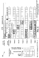
- Figure 8 depicts a timing diagram and a table illustrating one embodiment 800 of efficient cross-carrier and multi-slot scheduling.
- a base station e.g., the gNB 210 transmits DCI on a first component carrier CC1 815 (e.g., the scheduling carrier) to communicate a starting slot index (denoted herein as "SSI") and a number of contiguously scheduled slots, N, slots on a second component carrier CC2 820.
- SSI starting slot index
- N a number of contiguously scheduled slots
- the gNB 210 may use RRC signaling to configure a set of possible values, e.g., ⁇ 2, 4, 8, 16 ⁇ .
- N is a power of 2.
- the DCI 840 on component carrier CC1 815 includes a field to dynamically indicate which value of the possible values for N is to be used for scheduling N multiple slots on component carrier CC2 820.
- the set of possible values is semi-statically configured at the UE 205, while each DCI selects a member of the set.
- two bits may be included in DCI 840 to indicate the value of N from the set of values consisting of ⁇ 2, 4, 8, and 16 ⁇ .
- the gNB 210 also semi-statically configures the scheduled starting slot on CC2 820, e.g., via RRC signaling.
- the UE 205 may be configured with a set of possible starting slot index ("SSI") with respect to a beginning slot n on CC2 820, e.g., one value from the set of ⁇ 0, 2, 4, 8 ⁇ corresponding to actual starting slot index, n, n+2, n+4, n+8, respectively.
- SSI possible starting slot index
- a set of the possible values can be configured to determine the starting slot index SSI for multiple scheduled carrier slots 835 until such time as the SSI is updated.
- Embodiments that utilize a semi-statically configured SSI provide an advantage of some flexibility in changing the SSI from time to time without the overhead of including a separate SSI as part of each DCI 840.
- the selected SSI may be dynamically indicated in the DCI 840.
- the DCI 840 may include two bits for indicating the SSI from a preconfigured set of values, such as ⁇ 0, 2, 4, 8 ⁇ .
- certain particularly useful combinations of a starting slot index (SSI) and a number of contiguous scheduled slots (e.g., N) may be selected using a scheduling pattern P that may be encoded in as few as three bits of the DCI 840.
- Scheduling pattern table 850 illustrates one embodiment of a lookup table containing seven particularly useful combinations of SSI and N. Each of the seven particularly the useful combinations are shown in the timing view of Figure 8 .
- the DCI 840 includes three bits to indicate the pattern number "P" selected from the scheduling pattern table 850.
- the starting slot index SSI equals zero and N equals two, so two contiguous slots on component carrier CC2 820 are scheduled at slots n, and n+1.
- M is set to four, so the two scheduled slots 835 correspond to two HARQ processes 825 and no HARQ process bundling is required.
- Patterns 2, 3, and 4 similarly schedule two contiguous scheduled slots 835 on component carrier CC2 820 except that, as indicated by the starting slot index SSI, the two scheduled slots 835 slot start at n+2 for pattern 2, at n+4 for pattern 3, and at n+6 for pattern 4.
- N is not greater than M, no aggregation of multiple slots within one HARQ process 825 is needed.
- Pattern 5 and pattern 6 each schedule four contiguous slots on component carrier CC2 820.
- SSI is zero resulting in the scheduling of slots n, n+1, n+2, and n+3.
- SSI is four resulting in the scheduling of slots n+4, n+5, n+6, and n+7.
- N is equal to M. Because N is not greater than M, HARQ process bundling is not needed and each of the scheduled slots 835 corresponds to one HARQ process 825.
- Pattern 7 illustrates one embodiment of aggregating N multiple scheduled slots 835 within M HARQ processes 825 where N is greater than M.
- the number of slots per HARQ process is two.
- N/M equals two.
- the first two scheduled slots 835 (n, n+1) are aggregated into a first HARQ process 825.
- the second two scheduled slots 835 (n+2, n+3) are aggregated into a second HARQ process 825.
- the third two scheduled slots 835 (n+4, n+5) are aggregated into a third HARQ process 825.
- the fourth two scheduled slots 835 (n+6, n+7) are aggregated into a fourth HARQ process 825.
- component carrier CC1 815 schedules eight contiguous slots on component carrier CC2 820 without exceeding M the maximum number of HARQ processes 825 per DCI 840, which in this example is set to 4.
- certain combinations of starting slot index, N number of scheduled slots, and M maximum number of HARQ processes per DCI provide specific advantages of minimizing the total number of overhead bits associated with each DCI 840 while at the same time taking advantage of multi-slot scheduling on a component carrier CC2 with large subcarrier spacing (e.g., 120 kHz).
- Figure 9 illustrates various embodiments of efficient slot scheduling patterns.
- Figure 9 contrasts the scheduling pattern table 850, discussed above with respect to Figure 8 , with a first extended scheduling pattern table 900 and a second extended scheduling pattern table 920.
- the scheduling pattern table 850 is the same table shown in Figure 8 and illustrated in the timing diagram view of Figure 8 and is included in Figure 9 for comparison with scheduling pattern tables 900 and 920.
- the tables 900 and 920 operate substantially the same as the scheduling pattern table 850 with respect to the pattern number P, the starting slot index SSI, and N the number of scheduled slots 835.
- the patterns in tables 900 and 920 may be combined with the aggregation of multiple scheduled slots 835 within a lesser number of HARQ processes 825.
- the tables 900 and 920 may be understood without requiring timing diagram views of the tables 900 and 920.
- certain lessfrequently used patterns e.g., certain of patterns 1-6
- selected more-frequently used patterns e.g., pattern 8
- tables 900 and 920 each allow the DCI 840 to schedule slots 835 in component carrier CC2 820 that correspond to slot "m +1" on the component carrier CC1 815.
- the embodiments disclosed herein provide dynamic flexibility for multi-slot scheduling in carrier aggregation across component carriers having different numerologies.
- Figure 10 is a schematic flow chart diagram illustrating one embodiment of a method 1000 for efficient cross-carrier scheduling of multiple slots, according to embodiments of the disclosure.
- the method 1000 is performed by a remote unit, such as the remote unit 105, the UE 205, and/or the user equipment apparatus 300.
- the method 1000 may be performed by a processor executing program code, for example, a microcontroller, a microprocessor, a CPU, a GPU, an auxiliary processing unit, a FPGA, or the like.
- the method 1000 begins and receives 1005 a first control signal from a base station, such as the gNB 210.
- the first control signal indicates a maximum number of hybrid automatic repeat request ("HARQ") processes.
- HARQ hybrid automatic repeat request
- receiving 1005 the first control signal includes receiving an RRC signal from the base station.
- the first control signal also indicates an offset between the reception of the second control signal and a starting slot of the scheduled first number of slots.
- the first control signal also configures the remote unit with a set of scheduling values and/or a set of scheduling patterns.
- the first control signal may configure a set of size values which represent possible numbers of slots scheduled for the remote unit.
- the first control signal may configure a set of starting slot values which represent a slot offset amount with respect to a beginning slot of the slots on the second carrier the correspond to the slot on the first carrier in which the second control signal is received.
- the first control signal may configure a set of scheduling patterns as discussed above with reference to Figures 8 and 9 .
- each scheduling pattern indicates a starting slot and a number of scheduled slots.
- the method 1000 includes receiving 1010, from a base station, a second control signal on a first carrier.
- the second control signal schedules a first number of slots on a second carrier.
- the subcarrier spacing value of the first carrier is smaller than that of the second carrier.
- the second control signal includes DCI for multi-slot scheduling.
- the second control signal may indicate a particular member of a previously configured set of scheduling values or of a previously configured set of scheduling patterns.
- the second control signal indicates a slot aggregation granularity.
- the slot aggregation granularity indicates a number of the scheduled slots to be aggregated into a single HARQ process.
- the second control signal indicates an offset between the reception of the second control signal and a starting slot of the scheduled first number of slots.
- the method 1000 includes aggregating 1015 every two or more of the scheduled first number of slots to a single HARQ process in response to the first number being larger than the maximum number of HARQ processes. In certain embodiments, aggregating 1015 every two or more of the scheduled first number of slots to a single HARQ process also occurs in response to receiving a slot aggregation granularity parameter in the second control signal.
- aggregating 1015 every two or more of the scheduled first number of slots to a single HARQ process includes receiving one TB on each of the two or more slots aggregated in a single HARQ process. In other embodiments, aggregating 1015 every two or more of the scheduled first number of slots to a single HARQ process includes receiving a single TB over the two or more slots aggregated in a single HARQ process. In certain embodiments, the two or more slots aggregated in a single HARQ process are merged to form a single slot with larger duration. Where the scheduled slots are for downlink data transmission, aggregating 1015 every two or more of the scheduled first number of slots to a single HARQ process includes transmitting the aggregated HARQ-ACK feedback to the base station. The method 1000 ends.
- Figure 11 is a schematic flow chart diagram illustrating one embodiment of a method 1100 for efficient cross-carrier scheduling of multiple slots, according to embodiments of the disclosure.
- the method 1100 is performed by a base unit, such as the base unit 110, the gNB 210, and/or the base station apparatus 400.
- the method 1100 may be performed by a processor executing program code, for example, a microcontroller, a microprocessor, a CPU, a GPU, an auxiliary processing unit, a FPGA, or the like.
- the method 1100 begins and transmits 1105 a first control signal to a remote unit, such as the UE 205.
- the first control signal indicates a maximum number of hybrid automatic repeat request ("HARQ") processes.
- HARQ hybrid automatic repeat request
- transmitting 1105 the first control signal includes transmitting an RRC signal from the base station.
- the first control signal also indicates an offset between the reception of the second control signal and a starting slot of the scheduled first number of slots.
- the first control signal also configures the remote unit with a set of scheduling values and/or a set of scheduling patterns.
- the first control signal may configure a set of size values which represent possible numbers of slots scheduled for the remote unit.
- the first control signal may configure a set of starting slot values which represent a slot offset amount with respect to a beginning slot of the slots on the second carrier the correspond to the slot on the first carrier in which the second control signal is transmitted.
- the first control signal may configure a set of scheduling patterns as discussed above with reference to Figures 8 and 9 .
- each scheduling pattern indicates a starting slot and a number of scheduled slots.
- the method 1100 includes transmitting 1110, to the remote unit, a second control signal on a first carrier.
- the second control signal schedules a first number of slots on a second carrier.
- the subcarrier spacing value of the first carrier is smaller than that of the second carrier.
- the second control signal includes DCI for multi-slot scheduling.
- the second control signal may indicate a particular member of a previously configured set of scheduling values or of a previously configured set of scheduling patterns.
- the second control signal indicates a slot aggregation granularity.
- the slot aggregation granularity indicates a number of the scheduled slots to be aggregated into a single HARQ process.
- the second control signal indicates an offset between the reception of the second control signal and a starting slot of the scheduled first number of slots.
- the method 1100 includes aggregating 1115 every two or more of the scheduled first number of slots to a single HARQ process in response to the first number being larger than the maximum number of HARQ processes. In certain embodiments, aggregating 1115 every two or more of the scheduled first number of slots to a single HARQ process also occurs in response to transmitting a slot aggregation granularity parameter in the second control signal.
- aggregating 1115 every two or more of the scheduled first number of slots to a single HARQ process includes transmitting one TB on each of the two or more slots aggregated in a single HARQ process. In other embodiments, aggregating 1115 every two or more of the scheduled first number of slots to a single HARQ process includes transmitting a single TB over the two or more slots aggregated in a single HARQ process. In certain embodiments, the two or more slots aggregated in a single HARQ process are merged to form a single slot with larger duration. Where the scheduled slots are for downlink data transmission, aggregating 1115 every two or more of the scheduled first number of slots to a single HARQ process includes receiving the aggregated HARQ-ACK feedback from the remote unit. The method 1100 ends.
Landscapes
- Engineering & Computer Science (AREA)
- Signal Processing (AREA)
- Computer Networks & Wireless Communication (AREA)
- Mobile Radio Communication Systems (AREA)
Claims (15)
- Procédé (1000) comprenant:la réception (1005), en provenance d'une station de base, d'un premier signal de commande qui indique un nombre maximal de processus de demande de répétition automatique hybride, HARQ, etla réception (1010), en provenance de la station de base, d'un second signal de commande sur une première porteuse qui planifie un premier nombre de créneaux sur une seconde porteuse ; etl'agrégat (1015) tous les deux ou plus du premier nombre planifié de créneaux en un seul processus HARQ en réponse au fait que le premier nombre est supérieur au nombre maximal de processus HARQ.
- Procédé (1000) selon la revendication 1, comprenant en outre la transmission de données de liaison montante à la station de base sur le premier nombre planifié de créneaux en réponse au second signal de commande planifiant la transmission de données de liaison montante.
- Procédé (1000) selon la revendication 1, comprenant en outre la transmission d'une rétroaction d'accusé de réception HARQ, HARQ-ACK, à la station de base correspondant au premier nombre planifié de créneaux en réponse au second signal de commande planifiant la transmission de données de liaison descendante.
- Procédé (1000) selon la revendication 1, dans lequel le second signal de commande indique une granularité d'agrégat de créneaux, un nombre des créneaux agrégés dans un seul processus HARQ étant égal à la granularité d'agrégat de créneaux.
- Procédé (1000) selon la revendication 1, dans lequel le premier signal de commande configure en outre un ensemble de valeurs du premier nombre et le second signal de commande planifie le premier nombre de créneaux sur la seconde porteuse en indiquant une valeur à partir de l'ensemble.
- Procédé (1000) selon la revendication 1, dans lequel le premier signal de commande indique en outre un décalage entre la réception du second signal de commande et un créneau de départ du premier nombre planifié de créneaux.
- Procédé (1000) selon la revendication 1, dans lequel le second signal de commande indique en outre un décalage entre la réception du second signal de commande et un créneau de départ du premier nombre planifié de créneaux.
- Procédé (1000) selon la revendication 1, dans lequel le premier signal de commande configure en outre un ensemble de modèles de planification, chaque modèle de planification indiquant un créneau de départ et un nombre de créneaux planifiés, le second signal de commande planifiant le premier nombre de créneaux sur la seconde porteuse en indiquant un modèle de planification à partir de l'ensemble de modèles de planification configuré.
- Procédé (1000) selon la revendication 1, dans lequel une valeur d'espacement de sousporteuse de la première porteuse est inférieure à celle de la seconde porteuse.
- Procédé (1000) selon la revendication 1, comprenant en outre la réception d'un bloc de transport, TB, sur chacun des deux créneaux ou plus agrégés dans un seul processus HARQ.
- Procédé (1000) selon la revendication 1, comprenant en outre la réception d'un seul bloc de transport, TB, sur les deux intervalles ou plus agrégés en un seul processus HARQ.
- Procédé (1000) selon la revendication 1, dans lequel les deux créneaux ou plus agrégés dans un seul processus HARQ sont fusionnés pour former un créneau unique de plus grande durée.
- Appareil (105, 205, 300) comprenant un moyen destiné à réaliser le procédé (1000) selon l'une quelconque des revendications 1 à 12.
- Procédé (1100) comprenant :la transmission (1105), à une unité distante, d'un premier signal de commande qui indique un nombre maximal de processus de demande de répétition automatique hybride, HARQ, etla transmission (1110), à l'unité distante, d'un second signal de commande sur une première porteuse qui planifie un premier nombre de créneaux sur une seconde porteuse ; etl'agrégat (1115) tous les deux ou plus du premier nombre de créneaux planifiés en un seul processus HARQ en réponse au fait que le premier nombre est supérieur au nombre maximal de processus HARQ.
- Appareil (110, 210, 400) comprenant un moyen pour réaliser le procédé (1100) selon la revendication 14.
Applications Claiming Priority (1)
| Application Number | Priority Date | Filing Date | Title |
|---|---|---|---|
| PCT/CN2017/098013 WO2019033389A1 (fr) | 2017-08-18 | 2017-08-18 | Agrégation de multiples intervalles programmés, en une procédure harq |
Publications (3)
| Publication Number | Publication Date |
|---|---|
| EP3669598A1 EP3669598A1 (fr) | 2020-06-24 |
| EP3669598A4 EP3669598A4 (fr) | 2021-03-10 |
| EP3669598B1 true EP3669598B1 (fr) | 2022-07-06 |
Family
ID=65362655
Family Applications (1)
| Application Number | Title | Priority Date | Filing Date |
|---|---|---|---|
| EP17921594.2A Active EP3669598B1 (fr) | 2017-08-18 | 2017-08-18 | Agrégation de multiples intervalles programmés, en une procédure harq |
Country Status (4)
| Country | Link |
|---|---|
| US (2) | US11303416B2 (fr) |
| EP (1) | EP3669598B1 (fr) |
| CN (1) | CN111279767B (fr) |
| WO (1) | WO2019033389A1 (fr) |
Families Citing this family (32)
| Publication number | Priority date | Publication date | Assignee | Title |
|---|---|---|---|---|
| US11711171B2 (en) * | 2018-01-11 | 2023-07-25 | Huawei Technologies Co., Ltd. | System and method for reliable transmission over network resources |
| US11076447B2 (en) * | 2018-02-20 | 2021-07-27 | Intel Corporation | Efficient and reliable data transfer in 5G systems |
| EP3777435B1 (fr) * | 2018-04-04 | 2024-02-14 | ZTE Corporation | Procédé et appareil de réalisation de multiples procédures rach |
| CN111133703A (zh) * | 2018-04-04 | 2020-05-08 | Oppo广东移动通信有限公司 | 上行控制信息的传输方法及相关产品 |
| JP7160912B2 (ja) * | 2018-05-11 | 2022-10-25 | 株式会社Nttドコモ | 端末、無線通信方法、基地局及びシステム |
| US11277883B2 (en) * | 2018-05-11 | 2022-03-15 | Intel Corporation | Scheduling enhancements and hybrid automatic repeat request (HARQ) timing procedure for new radio (NR) unlicensed |
| US11330620B2 (en) * | 2018-08-10 | 2022-05-10 | Qualcomm Incorporated | Beam determination for a slot aggregation |
| CA3098094A1 (fr) * | 2018-08-23 | 2020-02-27 | Guangdong Oppo Mobile Telecommunications Corp., Ltd. | Procede et appareil de transmission d'information de retour et dispositif de communication |
| CN112655163A (zh) * | 2018-09-25 | 2021-04-13 | Oppo广东移动通信有限公司 | 一种反馈资源的复用方法、终端设备及网络设备 |
| CN111355562B (zh) * | 2018-12-21 | 2021-06-15 | 华为技术有限公司 | 数据传输方法和通信装置 |
| CN111586848B (zh) * | 2019-02-15 | 2023-05-30 | 大唐移动通信设备有限公司 | 一种调度时序确定方法、终端及网络侧设备 |
| US11582077B2 (en) * | 2019-02-25 | 2023-02-14 | Huawei Technologies Co., Ltd. | Systems and methods for transmission of uplink control information over multiple carriers in unlicensed spectrum |
| US11304039B2 (en) * | 2019-03-22 | 2022-04-12 | Lenovo (Singapore) Pte. Ltd. | Aggregating HARQ feedback |
| CN111757489A (zh) * | 2019-03-29 | 2020-10-09 | 中兴通讯股份有限公司 | 下行控制信息传输方法及装置 |
| US11350436B2 (en) | 2019-05-03 | 2022-05-31 | Qualcomm Incorporated | Downlink control indicator distribution for cross carrier scheduling |
| KR20200143126A (ko) | 2019-06-14 | 2020-12-23 | 삼성전자주식회사 | 무선 통신 시스템에서 상향링크 제어 채널들을 관리하기 위한 장치 및 방법 |
| US11552768B2 (en) * | 2019-07-22 | 2023-01-10 | Qualcomm Incorporated | Techniques for hybrid automatic repeat request (HARQ) processes for multiple carriers in different frequency ranges for carrier aggregation (CA) |
| CN112399620B (zh) * | 2019-08-16 | 2022-08-09 | 大唐移动通信设备有限公司 | 一种指示节能信息的方法、基站以及用户终端 |
| CN114451035A (zh) * | 2019-09-30 | 2022-05-06 | 华为技术有限公司 | 调度方法和装置 |
| US11606789B2 (en) | 2019-10-18 | 2023-03-14 | Qualcomm Incorporated | Asynchronous carrier aggregation slot alignment |
| KR20210088228A (ko) * | 2020-01-06 | 2021-07-14 | 삼성전자주식회사 | 무선 통신 시스템에서 동기 및 비동기 데이터의 재전송 방법 및 장치 |
| US11924846B2 (en) | 2020-07-27 | 2024-03-05 | Samsung Electronics Co., Ltd. | HARQ process identification and soft buffer management for non-terrestrial networks |
| EP4187827A4 (fr) * | 2020-08-06 | 2023-10-04 | Huawei Technologies Co., Ltd. | Procédé de programmation de ressources et appareil de communication |
| CN114070515A (zh) * | 2020-08-06 | 2022-02-18 | 上海朗帛通信技术有限公司 | 一种被用于无线通信的节点中的方法和装置 |
| WO2022051968A1 (fr) * | 2020-09-10 | 2022-03-17 | Qualcomm Incorporated | Techniques d'indication d'état de ressource de rétroaction pour communications sans fil |
| EP4197217A4 (fr) * | 2020-09-18 | 2024-05-01 | Apple Inc | Transmission de données basée sur un super-créneau dans une communication sans fil |
| EP4215000A4 (fr) * | 2020-09-18 | 2024-05-22 | Lenovo Beijing Ltd | Procédé et appareil pour transmissions multiples programmées par un seul format dci |
| EP4197257A4 (fr) * | 2020-09-18 | 2024-03-27 | Apple Inc | Opérations basées sur un réseau pour une transmission de données basée sur un super-créneau |
| EP4315685A1 (fr) * | 2021-03-22 | 2024-02-07 | Telefonaktiebolaget LM Ericsson (publ) | Opération harq pour bloc de transmission à multiples créneaux |
| CN115941126A (zh) * | 2021-08-03 | 2023-04-07 | 大唐移动通信设备有限公司 | Harq进程id确定方法、装置、设备及存储介质 |
| CN114205874A (zh) * | 2021-10-28 | 2022-03-18 | 华为技术有限公司 | 通信方法和装置 |
| US20240114502A1 (en) * | 2022-09-23 | 2024-04-04 | Qualcomm Incorporated | Inter-user equipment (ue) coordination for sidelink in an unlicensed or shared spectrum |
Family Cites Families (9)
| Publication number | Priority date | Publication date | Assignee | Title |
|---|---|---|---|---|
| US9635644B2 (en) * | 2012-08-10 | 2017-04-25 | Qualcomm Incorporated | Downlink coverage enhancements |
| US9445344B1 (en) * | 2014-07-22 | 2016-09-13 | Sprint Spectrum L.P. | Preferentially assigning data slots subject to bundled acknowledgments to devices that support carrier aggregation |
| US10652003B2 (en) * | 2015-01-22 | 2020-05-12 | Texas Instruments Incorporated | HARQ design for high performance wireless backhaul |
| WO2017052345A1 (fr) * | 2015-09-25 | 2017-03-30 | Samsung Electronics Co., Ltd. | Procédé et dispositif de renvoi et de réception d'informations de harq-ack |
| EP3761614A1 (fr) * | 2016-04-01 | 2021-01-06 | Samsung Electronics Co., Ltd. | Procédé et appareil de communication sans fil dans un système de communication sans fil |
| CN107682923B (zh) * | 2016-08-01 | 2023-05-12 | 北京三星通信技术研究有限公司 | 功率余量上报的方法及相应的用户设备 |
| EP3761696A1 (fr) * | 2016-09-29 | 2021-01-06 | NEC Corporation | Terminal radio, station de base et procédé associé |
| CN106385709B (zh) * | 2016-10-31 | 2022-12-20 | 宇龙计算机通信科技(深圳)有限公司 | 资源调度方法及资源调度装置 |
| US10595283B2 (en) * | 2016-11-22 | 2020-03-17 | Samsung Electronics Co., Ltd. | Method and apparatus for transmitting and receiving data of terminal |
-
2017
- 2017-08-18 EP EP17921594.2A patent/EP3669598B1/fr active Active
- 2017-08-18 US US16/640,016 patent/US11303416B2/en active Active
- 2017-08-18 CN CN201780093914.9A patent/CN111279767B/zh active Active
- 2017-08-18 WO PCT/CN2017/098013 patent/WO2019033389A1/fr unknown
-
2022
- 2022-04-11 US US17/718,202 patent/US11973720B2/en active Active
Also Published As
| Publication number | Publication date |
|---|---|
| CN111279767A (zh) | 2020-06-12 |
| CN111279767B (zh) | 2023-05-02 |
| US20200235891A1 (en) | 2020-07-23 |
| WO2019033389A1 (fr) | 2019-02-21 |
| US11973720B2 (en) | 2024-04-30 |
| EP3669598A1 (fr) | 2020-06-24 |
| EP3669598A4 (fr) | 2021-03-10 |
| US11303416B2 (en) | 2022-04-12 |
| US20220376873A1 (en) | 2022-11-24 |
Similar Documents
| Publication | Publication Date | Title |
|---|---|---|
| EP3669598B1 (fr) | Agrégation de multiples intervalles programmés, en une procédure harq | |
| US20220046675A1 (en) | Identifying a resource for transmitting a first uplink channel | |
| US20220385405A1 (en) | Ceasing transmission repetitions | |
| US11838128B2 (en) | Triggering HARQ-ACK feedback for a downlink slot set | |
| US20200374048A1 (en) | Harq-ack feedback timing for sps pdsch | |
| US10736136B2 (en) | Interlace determination for a device | |
| EP3665807B1 (fr) | Harq-ack pour une pluralité de groupes de porteuses d'un ensemble de créneaux de liaison descendante | |
| EP3665989A1 (fr) | Gestion dynamique de ressources de signalisation de commande de liaison montante dans un réseau sans fil | |
| US11653360B2 (en) | Carrier determination for a device | |
| WO2018120120A1 (fr) | Sélection de configuration de communication | |
| WO2018170916A1 (fr) | Indication de format pucch et attribution de ressources | |
| CN111108705B (zh) | 具有符号重复的信息 |
Legal Events
| Date | Code | Title | Description |
|---|---|---|---|
| STAA | Information on the status of an ep patent application or granted ep patent |
Free format text: STATUS: THE INTERNATIONAL PUBLICATION HAS BEEN MADE |
|
| PUAI | Public reference made under article 153(3) epc to a published international application that has entered the european phase |
Free format text: ORIGINAL CODE: 0009012 |
|
| STAA | Information on the status of an ep patent application or granted ep patent |
Free format text: STATUS: REQUEST FOR EXAMINATION WAS MADE |
|
| 17P | Request for examination filed |
Effective date: 20200302 |
|
| AK | Designated contracting states |
Kind code of ref document: A1 Designated state(s): AL AT BE BG CH CY CZ DE DK EE ES FI FR GB GR HR HU IE IS IT LI LT LU LV MC MK MT NL NO PL PT RO RS SE SI SK SM TR |
|
| AX | Request for extension of the european patent |
Extension state: BA ME |
|
| DAV | Request for validation of the european patent (deleted) | ||
| DAX | Request for extension of the european patent (deleted) | ||
| A4 | Supplementary search report drawn up and despatched |
Effective date: 20210204 |
|
| RIC1 | Information provided on ipc code assigned before grant |
Ipc: H04W 72/04 20090101AFI20210129BHEP |
|
| GRAP | Despatch of communication of intention to grant a patent |
Free format text: ORIGINAL CODE: EPIDOSNIGR1 |
|
| STAA | Information on the status of an ep patent application or granted ep patent |
Free format text: STATUS: GRANT OF PATENT IS INTENDED |
|
| INTG | Intention to grant announced |
Effective date: 20220209 |
|
| GRAS | Grant fee paid |
Free format text: ORIGINAL CODE: EPIDOSNIGR3 |
|
| GRAA | (expected) grant |
Free format text: ORIGINAL CODE: 0009210 |
|
| STAA | Information on the status of an ep patent application or granted ep patent |
Free format text: STATUS: THE PATENT HAS BEEN GRANTED |
|
| AK | Designated contracting states |
Kind code of ref document: B1 Designated state(s): AL AT BE BG CH CY CZ DE DK EE ES FI FR GB GR HR HU IE IS IT LI LT LU LV MC MK MT NL NO PL PT RO RS SE SI SK SM TR |
|
| REG | Reference to a national code |
Ref country code: AT Ref legal event code: REF Ref document number: 1503774 Country of ref document: AT Kind code of ref document: T Effective date: 20220715 Ref country code: CH Ref legal event code: EP |
|
| REG | Reference to a national code |
Ref country code: NL Ref legal event code: FP |
|
| REG | Reference to a national code |
Ref country code: DE Ref legal event code: R096 Ref document number: 602017059367 Country of ref document: DE |
|
| REG | Reference to a national code |
Ref country code: IE Ref legal event code: FG4D |
|
| REG | Reference to a national code |
Ref country code: LT Ref legal event code: MG9D |
|
| PG25 | Lapsed in a contracting state [announced via postgrant information from national office to epo] |
Ref country code: SE Free format text: LAPSE BECAUSE OF FAILURE TO SUBMIT A TRANSLATION OF THE DESCRIPTION OR TO PAY THE FEE WITHIN THE PRESCRIBED TIME-LIMIT Effective date: 20220706 Ref country code: RS Free format text: LAPSE BECAUSE OF FAILURE TO SUBMIT A TRANSLATION OF THE DESCRIPTION OR TO PAY THE FEE WITHIN THE PRESCRIBED TIME-LIMIT Effective date: 20220706 Ref country code: PT Free format text: LAPSE BECAUSE OF FAILURE TO SUBMIT A TRANSLATION OF THE DESCRIPTION OR TO PAY THE FEE WITHIN THE PRESCRIBED TIME-LIMIT Effective date: 20221107 Ref country code: NO Free format text: LAPSE BECAUSE OF FAILURE TO SUBMIT A TRANSLATION OF THE DESCRIPTION OR TO PAY THE FEE WITHIN THE PRESCRIBED TIME-LIMIT Effective date: 20221006 Ref country code: LV Free format text: LAPSE BECAUSE OF FAILURE TO SUBMIT A TRANSLATION OF THE DESCRIPTION OR TO PAY THE FEE WITHIN THE PRESCRIBED TIME-LIMIT Effective date: 20220706 Ref country code: LT Free format text: LAPSE BECAUSE OF FAILURE TO SUBMIT A TRANSLATION OF THE DESCRIPTION OR TO PAY THE FEE WITHIN THE PRESCRIBED TIME-LIMIT Effective date: 20220706 Ref country code: FI Free format text: LAPSE BECAUSE OF FAILURE TO SUBMIT A TRANSLATION OF THE DESCRIPTION OR TO PAY THE FEE WITHIN THE PRESCRIBED TIME-LIMIT Effective date: 20220706 Ref country code: ES Free format text: LAPSE BECAUSE OF FAILURE TO SUBMIT A TRANSLATION OF THE DESCRIPTION OR TO PAY THE FEE WITHIN THE PRESCRIBED TIME-LIMIT Effective date: 20220706 |
|
| REG | Reference to a national code |
Ref country code: AT Ref legal event code: MK05 Ref document number: 1503774 Country of ref document: AT Kind code of ref document: T Effective date: 20220706 |
|
| PG25 | Lapsed in a contracting state [announced via postgrant information from national office to epo] |
Ref country code: PL Free format text: LAPSE BECAUSE OF FAILURE TO SUBMIT A TRANSLATION OF THE DESCRIPTION OR TO PAY THE FEE WITHIN THE PRESCRIBED TIME-LIMIT Effective date: 20220706 Ref country code: IS Free format text: LAPSE BECAUSE OF FAILURE TO SUBMIT A TRANSLATION OF THE DESCRIPTION OR TO PAY THE FEE WITHIN THE PRESCRIBED TIME-LIMIT Effective date: 20221106 Ref country code: GR Free format text: LAPSE BECAUSE OF FAILURE TO SUBMIT A TRANSLATION OF THE DESCRIPTION OR TO PAY THE FEE WITHIN THE PRESCRIBED TIME-LIMIT Effective date: 20221007 |
|
| REG | Reference to a national code |
Ref country code: CH Ref legal event code: PL |
|
| REG | Reference to a national code |
Ref country code: DE Ref legal event code: R097 Ref document number: 602017059367 Country of ref document: DE |
|
| PG25 | Lapsed in a contracting state [announced via postgrant information from national office to epo] |
Ref country code: SM Free format text: LAPSE BECAUSE OF FAILURE TO SUBMIT A TRANSLATION OF THE DESCRIPTION OR TO PAY THE FEE WITHIN THE PRESCRIBED TIME-LIMIT Effective date: 20220706 Ref country code: RO Free format text: LAPSE BECAUSE OF FAILURE TO SUBMIT A TRANSLATION OF THE DESCRIPTION OR TO PAY THE FEE WITHIN THE PRESCRIBED TIME-LIMIT Effective date: 20220706 Ref country code: MC Free format text: LAPSE BECAUSE OF FAILURE TO SUBMIT A TRANSLATION OF THE DESCRIPTION OR TO PAY THE FEE WITHIN THE PRESCRIBED TIME-LIMIT Effective date: 20220706 Ref country code: LU Free format text: LAPSE BECAUSE OF NON-PAYMENT OF DUE FEES Effective date: 20220818 Ref country code: LI Free format text: LAPSE BECAUSE OF NON-PAYMENT OF DUE FEES Effective date: 20220831 Ref country code: DK Free format text: LAPSE BECAUSE OF FAILURE TO SUBMIT A TRANSLATION OF THE DESCRIPTION OR TO PAY THE FEE WITHIN THE PRESCRIBED TIME-LIMIT Effective date: 20220706 Ref country code: CZ Free format text: LAPSE BECAUSE OF FAILURE TO SUBMIT A TRANSLATION OF THE DESCRIPTION OR TO PAY THE FEE WITHIN THE PRESCRIBED TIME-LIMIT Effective date: 20220706 Ref country code: CH Free format text: LAPSE BECAUSE OF NON-PAYMENT OF DUE FEES Effective date: 20220831 Ref country code: AT Free format text: LAPSE BECAUSE OF FAILURE TO SUBMIT A TRANSLATION OF THE DESCRIPTION OR TO PAY THE FEE WITHIN THE PRESCRIBED TIME-LIMIT Effective date: 20220706 |
|
| PLBE | No opposition filed within time limit |
Free format text: ORIGINAL CODE: 0009261 |
|
| STAA | Information on the status of an ep patent application or granted ep patent |
Free format text: STATUS: NO OPPOSITION FILED WITHIN TIME LIMIT |
|
| PG25 | Lapsed in a contracting state [announced via postgrant information from national office to epo] |
Ref country code: SK Free format text: LAPSE BECAUSE OF FAILURE TO SUBMIT A TRANSLATION OF THE DESCRIPTION OR TO PAY THE FEE WITHIN THE PRESCRIBED TIME-LIMIT Effective date: 20220706 Ref country code: EE Free format text: LAPSE BECAUSE OF FAILURE TO SUBMIT A TRANSLATION OF THE DESCRIPTION OR TO PAY THE FEE WITHIN THE PRESCRIBED TIME-LIMIT Effective date: 20220706 |
|
| 26N | No opposition filed |
Effective date: 20230411 |
|
| PG25 | Lapsed in a contracting state [announced via postgrant information from national office to epo] |
Ref country code: AL Free format text: LAPSE BECAUSE OF FAILURE TO SUBMIT A TRANSLATION OF THE DESCRIPTION OR TO PAY THE FEE WITHIN THE PRESCRIBED TIME-LIMIT Effective date: 20220706 |
|
| PG25 | Lapsed in a contracting state [announced via postgrant information from national office to epo] |
Ref country code: IE Free format text: LAPSE BECAUSE OF NON-PAYMENT OF DUE FEES Effective date: 20220818 Ref country code: FR Free format text: LAPSE BECAUSE OF NON-PAYMENT OF DUE FEES Effective date: 20220906 |
|
| P01 | Opt-out of the competence of the unified patent court (upc) registered |
Effective date: 20230627 |
|
| PG25 | Lapsed in a contracting state [announced via postgrant information from national office to epo] |
Ref country code: SI Free format text: LAPSE BECAUSE OF FAILURE TO SUBMIT A TRANSLATION OF THE DESCRIPTION OR TO PAY THE FEE WITHIN THE PRESCRIBED TIME-LIMIT Effective date: 20220706 |
|
| PGFP | Annual fee paid to national office [announced via postgrant information from national office to epo] |
Ref country code: NL Payment date: 20230825 Year of fee payment: 7 |
|
| PGFP | Annual fee paid to national office [announced via postgrant information from national office to epo] |
Ref country code: GB Payment date: 20230822 Year of fee payment: 7 |
|
| PGFP | Annual fee paid to national office [announced via postgrant information from national office to epo] |
Ref country code: DE Payment date: 20230828 Year of fee payment: 7 Ref country code: BE Payment date: 20230825 Year of fee payment: 7 |
|
| PG25 | Lapsed in a contracting state [announced via postgrant information from national office to epo] |
Ref country code: IT Free format text: LAPSE BECAUSE OF FAILURE TO SUBMIT A TRANSLATION OF THE DESCRIPTION OR TO PAY THE FEE WITHIN THE PRESCRIBED TIME-LIMIT Effective date: 20220706 |
|
| PG25 | Lapsed in a contracting state [announced via postgrant information from national office to epo] |
Ref country code: HR Free format text: LAPSE BECAUSE OF FAILURE TO SUBMIT A TRANSLATION OF THE DESCRIPTION OR TO PAY THE FEE WITHIN THE PRESCRIBED TIME-LIMIT Effective date: 20220706 Ref country code: CY Free format text: LAPSE BECAUSE OF FAILURE TO SUBMIT A TRANSLATION OF THE DESCRIPTION OR TO PAY THE FEE WITHIN THE PRESCRIBED TIME-LIMIT Effective date: 20220706 |