EP3669575B1 - Verfahren und vorrichtungen zur reduzierung der netzwerklatenz - Google Patents
Verfahren und vorrichtungen zur reduzierung der netzwerklatenz Download PDFInfo
- Publication number
- EP3669575B1 EP3669575B1 EP18870532.1A EP18870532A EP3669575B1 EP 3669575 B1 EP3669575 B1 EP 3669575B1 EP 18870532 A EP18870532 A EP 18870532A EP 3669575 B1 EP3669575 B1 EP 3669575B1
- Authority
- EP
- European Patent Office
- Prior art keywords
- node
- network
- pincs
- ncc
- network condition
- Prior art date
- Legal status (The legal status is an assumption and is not a legal conclusion. Google has not performed a legal analysis and makes no representation as to the accuracy of the status listed.)
- Not-in-force
Links
Images




Classifications
-
- H—ELECTRICITY
- H04—ELECTRIC COMMUNICATION TECHNIQUE
- H04W—WIRELESS COMMUNICATION NETWORKS
- H04W24/00—Supervisory, monitoring or testing arrangements
- H04W24/08—Testing, supervising or monitoring using real traffic
-
- H—ELECTRICITY
- H04—ELECTRIC COMMUNICATION TECHNIQUE
- H04W—WIRELESS COMMUNICATION NETWORKS
- H04W28/00—Network traffic management; Network resource management
- H04W28/02—Traffic management, e.g. flow control or congestion control
- H04W28/0289—Congestion control
-
- H—ELECTRICITY
- H04—ELECTRIC COMMUNICATION TECHNIQUE
- H04W—WIRELESS COMMUNICATION NETWORKS
- H04W28/00—Network traffic management; Network resource management
- H04W28/02—Traffic management, e.g. flow control or congestion control
- H04W28/08—Load balancing or load distribution
- H04W28/084—Load balancing or load distribution among network function virtualisation [NFV] entities; among edge computing entities, e.g. multi-access edge computing
-
- H—ELECTRICITY
- H04—ELECTRIC COMMUNICATION TECHNIQUE
- H04W—WIRELESS COMMUNICATION NETWORKS
- H04W84/00—Network topologies
- H04W84/02—Hierarchically pre-organised networks, e.g. paging networks, cellular networks, WLAN [Wireless Local Area Network] or WLL [Wireless Local Loop]
- H04W84/04—Large scale networks; Deep hierarchical networks
- H04W84/042—Public Land Mobile systems, e.g. cellular systems
Definitions
- the present disclosure is related to method and apparatuses for reducing latency in a communication system.
- 5G fifth generation
- 4G fourth generation
- 5G provides higher bandwidth with much higher device density.
- the proposed 5G networks may be useful for implementing new applications such as online augmented reality (AR), remote surgery, internet of things (IoT), and vehicle to vehicle (V2V) communication.
- AR online augmented reality
- IoT internet of things
- V2V vehicle to vehicle
- US 2016/0352865 A1 refers to techniques for extending a two-way active measurement protocol (TWAMP) to enable measurement of service key performance indicators (KPIs) in a software defined network (SDN) and network function virtualization (NFV) architecture.
- TWAMP active measurement protocol
- KPIs service key performance indicators
- SDN software defined network
- NFV network function virtualization
- the TWAMP extensions enable control messaging to be handled by a TWAMP control client executed on a centralized controller, and data messaging to be handled by a TWAMP session initiator executed on a separate network device.
- Techniques are also described for extending TWAMP to enable measurement of any of a plurality of service KPIs for a given service supported at a TWAMP server.
- the service KPIs may include one or more of keepalive measurements, round trip time measurements, path delay measurements, service latency measurements, or service load measurements.
- the TWAMP extensions for the service KPIs may be used in both conventional network architectures and in SDN and
- apparatus in a network including a processing system configured to implement a protocol independent network condition service (PINCS) node, the processing system being configured to: receive a subscription for network condition information of at least one network from at least one network condition consumer (NCC) node, the network condition information being related to at least one target data flow provided to at least one node in the network via the NCC node; obtain information about a plurality of network conditions from at least one network condition provider (NCP) node configured to provide a plurality of network conditions including network conditions related to the at least one target data flow; aggregate the information about the plurality of network conditions; and send the aggregated information about the plurality of network conditions to the NCC node, as indicated by the subscription.
- PNCS protocol independent network condition service
- the information of the plurality of network conditions includes information concerning multiple data flows, including the at least one target data flow, the multiple data flows operating according to a plurality of protocols.
- a protocol independent network condition service (PINCS) apparatus comprising: a non-transitory memory storage comprising instructions; and one or more processors in communication with the memory, wherein the one or more processors execute the instructions to: receive a subscription for network condition information of at least one network from at least one network condition consumer (NCC) node, the network condition information being related to at least one target data flow provided to at least one node in the network via the NCC node; obtain information about a plurality of network conditions from at least one network condition provider (NCP) node configured to monitor a plurality of network conditions including network conditions related to the at least one target data flow; process the information about the plurality of network conditions to generate an aggregated network conditions information; and send the aggregated network conditions information the NCC node as indicated by the subscription.
- NCC network condition consumer
- NCP network condition provider
- the information of the plurality of network conditions includes information concerning multiple data flows, including the at least one target data flow, the multiple data flows operating according to a plurality of protocols.
- the network condition information includes at least one of: a radio bandwidth, a round trip time (RTT), a bearer queue length, a flow queue length, a bearer queue depletion rate, or a flow queue depletion rate.
- RTT round trip time
- the processing system is configured to receive respective subscriptions from a plurality of NCC nodes related to a respective plurality of data flows and to receive the network condition information from a plurality of network condition providers.
- the processing system is a component of a network exposure function of a fifth generation (5G) system.
- 5G fifth generation
- the processing system is coupled to a mobile edge computing (MEC) system including a MEC server and the processing system and the MEC server are in separate locations.
- MEC mobile edge computing
- the processing system is coupled to a mobile edge computing (MEC) system including a MEC server and the processing system and the MEC server are co-located.
- MEC mobile edge computing
- the processing system is configured to receive side information from a Node B such as radio channel and quality of service (QoS) aware segmentation of the momentary cell capacity and S1 interface, throughput, loss, queue length, average queue depletion rate, and delay.
- QoS quality of service
- a network condition consumer (NCC) apparatus comprising: a non-transitory memory storage comprising instructions; and one or more processors in communication with the memory, wherein the one or more processors execute the instructions to: send a subscription for network condition information of at least one network to a protocol independent network condition service (PINCS) node, the network condition information being related to at least one target data flow provided to at least one node in the network by a source node coupled to the NCC node; obtain information about a plurality of network conditions from the PINCS node as indicated in the subscription; and apply the information about the plurality of network conditions to control network congestion and to reduce latency for the target data flow from the source node.
- PNCS protocol independent network condition service
- the NCC node is collocated with the source node and the processing system is configured to implement the congestion control in network transport.
- the processing system is configured to implement rate control.
- the processing system is configured to implement buffer control.
- the NCC node is separate from the source node and the processing system is configured to send the information about the plurality of network conditions to the source node using in-band signaling.
- the NCC node is separate from the source node and the processing system is configured to send the information about the plurality of network conditions to the source node using out-of-band signaling.
- the network conditions in the subscription include at least one of: a radio bandwidth, a round trip time (RTT), a bearer queue length, a flow queue length, a bearer queue depletion rate, or a flow queue depletion rate.
- RTT round trip time
- a network condition provider (NCP) apparatus comprising: a non-transitory memory storage comprising instructions; and one or more processors in communication with the memory, wherein the one or more processors execute the instructions to: periodically obtain network condition information about a plurality of data flows provided to one or more UE devices from a radio access technology (RAT) device; receive, from a protocol independent network condition service (PINCS) node, a request for information about network conditions related to at least one flow of the plurality of data flows; and periodically send the requested information to the PINCS node.
- RAT radio access technology
- PNCS protocol independent network condition service
- the NCP node is collocated with the RAT device and is configured to directly monitor the data flows provided by the RAT device to the one or more UE devices.
- the NCP node is separate from the RAT device and collects the network condition information by periodically sending probe packets to the RAT device and monitoring responses to the probe packets received from the RAT device.
- the probe packets include polling requests for information maintained by the RAT device.
- a method for implementing a Protocol Independent Network Condition Service comprising: receiving a subscription for network condition information of at least one network from at least one network condition consumer (NCC) node, the network condition information being related to at least one target data flow provided to at least one node in the network via the NCC node; obtaining information about a plurality of network conditions from at least one network condition provider (NCP) node configured to monitor a plurality of network conditions including network conditions related to the at least one target data flow; process the information about the plurality of network conditions to generate an aggregated network conditions information; and send the aggregated network conditions information the NCC node as indicated by the subscription.
- NCP network condition provider
- the information of the plurality of network conditions includes information concerning multiple data flows, the multiple data flows operating according to a plurality of protocols.
- the network condition information includes at least one of radio bandwidth, round trip time (RTT), bearer queue length, flow queue length, bearer queue depletion rate, flow queue depletion rate.
- RTT round trip time
- the method further includes receiving respective subscriptions from a plurality of NCC nodes related to a respective plurality of target data flows; receiving the network condition information from a plurality of network condition providers; and maintaining the network condition information from the plurality of network condition providers in the list.
- Ultra-low latency applications such as augmented reality (AR), remote surgery, internet of things (IoT), and vehicle to vehicle (V2V) communication benefit from reductions in end-to-end delay.
- MEC Mobile edge computing
- eNBs enhanced NodeBs
- gNBs next generation NodeBs
- the MEC system may have a MEC server collocated with the eNB or gNB, for example, at a central office (CO) of the network.
- CO central office
- Moving content servers to the edge does not address all of the latency issues in the edge network, because queueing delay is the dominant cause of end to end latency in cellular networks. Such queueing delay is also called bufferbloat. End-to-end latency in many existing Internet applications is the result of bufferbloat.
- routers include buffers to absorb traffic bursts, and avoid loss of data. Bufferbloat occurs as a consequence of excessively large buffers at network devices, especially at routers, which cause significant delay.
- bufferbloat exists in both radio access network (RAN) and core network (CN) functions.
- RAN radio access network
- CN core network
- Existing mechanisms in buffer control and/or congestion/rate control/avoidance such as additive-increase/multiplicative-decrease (AIMD) algorithm, are loss based and so do not focus on reducing round-trip time (RTT).
- RTT round-trip time
- edge resources are co-located, such as core network entities like distributed gateway (DGW), over the top (OTT) entities such as streaming servers, and radio access network (RAN) entities.
- DGW distributed gateway
- OTT over the top
- RAN radio access network
- UE user equipment
- RAN radio access network
- Such a cooperative resource scheduling approach complements the existing efforts, such as content delivery network (CDN), MEC, and control and user plane separation (CUPS), helps in business collaboration opportunities in edges between network operators and OTT entities, and allows building differentiated subscriber service pipes for OTT entities to create value added opportunities.
- CDN content delivery network
- MEC mobility control and user plane separation
- CUPS control and user plane separation
- FIG. 1 shows a prior art communication network 100 having multiple nodes, including an edge server 102, a core network/distributed gateway (CN/DGW) 108, a RAT 112, a DGW 114, and a RAN 118.
- the edge server 102 communicates via a wireless network 104 with the CN/DGW 108, the RANs 112 and 118 and, via the RAN 112, with the DGW 114.
- the nodes 108, 112, 114 and 118 in turn, communicate with a plurality of UEs 106.
- the UEs 106 may be smart phones or tablet devices, or other types of devices including, without limitation, Internet video players, IoT devices, virtual reality (VR) devices, or V2V devices.
- VR virtual reality
- each of the DGW 114, CN/DGW 108, and RAT device 118 includes a respective buffer 116, 110 and 120.
- These buffers temporarily hold data to be provided to applications running on the UEs 106. Buffering of the data is handled on an application-by-application basis, with little or no regard to the state of the communication network 100.
- the buffers 116, 110 and 120 may be relatively large in order to prevent data loss. Depending on the status of the communication network 100, the buffer may add significant latency to one or more of the applications running on the UEs 106.
- multiple UEs 106 running video players may request separate high-resolution video streams.
- the bandwidth used to transmit the streams from the devices 108, 112, and/or 118 may be greater than the available bandwidth in the respective radio link. In this instance, data may back up in the queue and none of the users of the UEs 106 will have a satisfactory experience.
- BDP is at the maximum bottleneck bandwidth and minimum RTT.
- the BDP may be difficult to determine because it may be difficult to measure RTT/delay and bottleneck bandwidth together.
- One method of utilizing BDP is the bottleneck bandwidth and round-trip time (BBR) proposed by Google which seeks high throughput with small queue size by probing bottleneck bandwidth (BW) and RTT sequentially.
- BBR bottleneck bandwidth and round-trip time
- the BBR method models the network path and dynamically estimates max BW and min RTT on each acknowledgment message (ACK) received via the network path.
- the method controls the rate at which data is sent from the source to the application based on the model.
- the method uses probe measurements of max BW and min RTT to feed the model samples and attempts to maintain a data rate near the estimated BW to reduce queues and loss.
- BBR may have difficulty getting accurate BW and RTT estimates for the fluctuating links of a wireless network. These links may fluctuate due to: packet loss in the air interface, fluctuations in cellular transmission capability, dynamics of users (e.g. their flows, mobility, and associated delay changes), proprietary packet buffering mechanisms in base station and gateways, and interference from quality of service (QoS) mechanisms implemented in the RAN and CN nodes.
- QoS quality of service
- One approach may be to provide help from the network side to assist in obtaining the BW and RTT estimates used in BBR. More specifically, embodiments below describe a protocol independent network condition service (PINCS) node to be used by the traffic source.
- PINCS protocol independent network condition service
- the PINCS node controls the source servers to send packets at a rate to minimize queuing delay within the path.
- a data driven mechanism in the PINCS node considers network congestion data from multiple sources (that may use different protocols) to obtain real-time scheduling data.
- the embodiments described below complement existing rate control mechanisms implemented at the transport level and/or application level.
- FIG. 2 is a block diagram showing a communication network 200 according to an embodiment.
- the communication network 200 includes a PINCS node 210, a DGW 214, a CN/DGW 208 and RAT devices 212 and 218.
- the example PINCS node 210 receives network status data from the 3GPP network 204 (e.g. the CN/DGW 208) and also receives network usage data from an edge server 202.
- the edge server 202 which may be a MEC server, in turn receives usage data from the RAT devices 212 and 218.
- the RAT devices 212 and/or 218 in some examples comprise eNBs or gNBs.
- a single PINCS node 210 may be used to collect and distribute network status information from a single network 204 or from multiple networks.
- An additional network may include additional nodes (e.g. DGWs and RAT devices) as well as an additional edge server. For the sake of clarity, the connections among these additional elements are not shown in FIG. 2 .
- the PINCS node 210 receives, consolidates, and distributes network condition information from both the network 104 and any additional networks.
- the example PINCS node 210 serves as an intelligence center that collects information from multiple sources, conducts analysis and computation, and provides a secure interface for accessing and obtaining network conditions, such as BW and delay.
- the PINCS node 210 may also consider side information from the eNB/gNB such as radio channel and QoS aware segmentation of the momentary cell capacity and S1. Side information includes information such as throughput, loss, queue length, average queue depletion rate, and delay.
- the PINCS node 210 may also receive information from one or more network condition providers (NCP) nodes and one or more network condition consumers (NCC) nodes, as described below.
- NCP network condition providers
- NCC network condition consumers
- a network congestion controller in some embodiments includes a protocol independent network condition service (PINCS) node, a network condition consumer (NCC) node, and a network condition provider (NCP) node.
- PINCS protocol independent network condition service
- NCC network condition consumer
- NCP network condition provider
- the PINCS node receives a subscription for network condition information of at least one network from the NCC node and obtains information about a plurality of network conditions from the NCP node.
- the PINCS node aggregates the information about the plurality of network conditions and sends the aggregated information about the plurality of network conditions to the NCC node as indicated by the subscription.
- the NCP node applies the subscribed network condition information to implement congestion control, rate control and/or buffer control in the network.
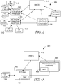
- Each example NCP node 302, 304 establishes a secure channel with the PINCS node 310.
- the NCP node 302, 304 can be an in-line entity such as a baseband unit (BBU) or external entity such as a probe agent.
- a probe agent may, for example, obtain network condition information by periodically sending probe packets to the BBU and monitoring responses received from the BBU. Alternatively, the probe agent may poll the BBU with requests for network condition information maintained by the BBU, such as radio bandwidth and queue length for both the bearer queues and the flow queues.
- the NCP node 302, 304 may periodically provide network condition information to the PINCS node 310, or may provide information when it is requested.
- An in-line NCP node 302, 304 collects information such as radio bandwidth, delay (e.g. RTT), and, for each per-bearer and/or per-flow queue, queue length and average depletion rate of the queue.
- the NCP node 302, 304 sends the collected data to the PINCS node 310.
- An external NCP node 302, 304 probes or polls the network elements to collect throughput, delay and/or loss information and sends the collected information to the PINCS node 310.
- the example PINCS systems described below allow for flexible implementation.
- the NCP node 302, 304 can be an inline or external provider node, the NCC node 306 can run in direct or indirect mode, and the PINCS function can be deployed in the application layer or as congestion/rate control in the transport layer.
- the example PINCS systems can be used in different scenarios to assist in congestion control, rate control, slow start, and/or to control other aspects of data dissemination using the network.
- the PINCS node 310 operating in indirect mode, implements in-line processing at the gateway.
- One or more in-line components of the gateway such as the policy and charging enforcement function (PCEF) becomes the NCC node 306 and subscribes to receive data from the PINCS node 310.
- the gateway 306 adds an option header in the TCP session to notify the TCP sender to adjust the data rate for example, using TCP-EDO.
- PCEF policy and charging enforcement function
- the protocol independent nature of the PINCS node 310 allows this service to be used by congestion control modules in one or more other protocols.
- a UDP sender e.g. traffic source 308 may subscribe to congestion data from the PINCS node 310.
- the information from PINCS node 310 may be used to adjust the sending rate to implement rate control in the application (e.g. to control the video/content delivery rate).
- FIG. 4A is a block diagram of an example embodiment which includes a PINCS node 410, one or more traffic sources 408, each including an NCC node 409, one or more TCP baseband units (BBUs) 402, each including an NCP node 403, and one or more UEs 312. Operation of the each of the elements 402, 403, 408, 409, and 410 is described below with reference to the flowcharts 4B, 4C and 4D.
- the example system 400 uses an NCC node 409 running in direct mode at the TCP Source 408. In this example, the NCC node 409 runs TCP BBR (bottleneck bandwidth and RTT).
- TCP BBR bottleneck bandwidth and RTT
- a similar architecture and flow may be used for other congestion control mechanisms, such as, without limitation, Cubic, Vegas and Tahoe, and/or for other transport layer protocols and/or application layer rate control mechanisms with or without BBR.
- the BBU may use other protocols such as, without limitation, user datagram protocol (UDP), datagram congestion control protocol (DCCP), stream control transmission protocol (SCTP), and may be implemented in a number of RAT devices such as, without limitation, a base station, a gateway, an access point, an a micro node, a pico-node, a femto-node, an eNB and/or a gNB may be used for the data flow between the BBU and the UE 312.
- UDP user datagram protocol
- DCCP datagram congestion control protocol
- SCTP stream control transmission protocol
- RAT devices such as, without limitation, a base station, a gateway, an access point, an a micro node, a pico-node, a femto-node
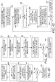
- FIG. 4B is a flowchart showing operations performed by an example NCP node 403, such as the NCP node 403 in the BBU node 402, shown in FIG. 4A .
- the NCP node 403 registers and establishes a secure channel with the PINCS node 410.
- the NCP node 403, at block 414 optionally receives filter information from the PINCS node 410 via the secure channel.
- the filter information indicates the traffic data to be monitored by the NCP node 403.
- information to be monitored may identify a target data flow of interest and request the bandwidth, delay, queue length, and/or queue depletion rate for the target data flow as well as an indication of the quality of the channel between the BBU 402 and the UEs 312 used by the target data flow.
- the NCP node 403 may provide network condition information for multiple data flows operating according to multiple protocols (e.g. TCP, UDP, datagram congestion control protocol (DCCP), flow control transmission protocol (SCTP), etc.), as well as the number and type of applications being serviced by the BBU 402.
- the NCP node may provide similar condition information for different bearers.
- FIG. 4C is a flowchart diagram showing the operation of an example PINCS node 410.
- the PINCS node 410 receives registration requests from one or more NCP nodes 403.
- the PINCS node 410 based on subscription requests from the NCC nodes 409, may also send, to the NCP nodes 403, filter data indicating particular flows, bearers and/or network condition parameters to be monitored.
- the PINCS node 410 receives registration requests and subscriptions for specific network condition data from one or more NCC nodes 409.
- the PINCS node 410 receives network condition information from the NCP nodes 403.
- FIG. 4D is a flowchart diagram showing the operation of an example NCC node 409, shown in FIG. 4A .
- the NCC node 409 establishes a secure channel with the PINCS node 410.
- the NCC node 409 then subscribes to receive specific traffic condition information from the PINCS node 410.
- the subscribed traffic conditions may depend on the types of data flows being provided by the traffic source 408. For example, if the traffic source is a streaming video source, the NCC node 409 may subscribe to receive RTT, bandwidth, queue length and queue length depletion rate from the NCP nodes 403 that are monitoring the streaming video being provided to the UEs 312.
- the requested information may include the TCP 5-tuple (source IP address/port number, destination IP address/port number and the protocol in uses) with a request to monitor bandwidth and queues linked to the bearer channel indicated by the 5-tuple.
- TCP 5-tuple source IP address/port number, destination IP address/port number and the protocol in uses
- the NCC node 409 receives the subscribed network condition information from the PINCS node 410.
- the example NCC node 409 implements BBR control based on the data to adjust the data source toward the maximum bandwidth and minimum latency for the flows subscribed to by the NCC node 409.
- the NCC node 409 can perform a better BBR control than is presently performed because it has access to network condition information for all of the applications served by a traffic source through multiple BBUs. This network condition information is independent of the protocol being used.
- the example BBR control of block 458 is for a TCP application and includes, at step 460, monitoring draining of the buffers and recording the maximum bandwidth and minimum round-trip time while the buffer is drained.
- the NCC node 409 may also receive the probe bandwidth data and probed RTT data from the NCP nodes 403, via the PINCS node 410. Also at block 462, the NCC node 409 may update the maximum bandwidth and maximum RTT measurements based on the received probe data.
- the NCC node 409 updates the congestion control parameters for the traffic source 408 based on the probe results and the PINCS node 410 results according to the BBR control.
- the NCC node 409 is shown as implementing a BBR control, it is contemplated that other types of control may be used for other protocols.
- the NCC node 409 may subscribe to the queue length and bandwidth of the access point that is providing data to the UE 312 and increase the frame rate or resolution of the video when the queue length decreases and/or the bandwidth increases and decrease the frame rate or resolution of the video when the queue length increases and/or the bandwidth decreases.
- the information collected by the PINCS node 410 may be low-pass filtered and/or that the NCC node 409 may apply hysteresis to prevent rapid changes in the data rates from causing rapid changes in the BBR control.
- the NCC node 409 branches to block 456 if it continues to update the congestion control parameters and branches to block 468 otherwise.
- the NCC node 409 terminates its operations and de-registers from the PINCS node 410.
- FIG. 5A is a block diagram of another example embodiment of the system 500.
- the example system 500 includes a PINCS node 510, one or more TCP traffic source nodes 512, one or more TCP gateway nodes 508, at least some of the TCP gateway nodes 508 including respective NCC nodes 509, one or more TCP BBU nodes 502 including respective NCP nodes 503, and one or more UE clients 312.
- the NCC node 509 runs in indirect mode at the TCP gateway node 508.
- the gateway adds inband signal handling (e.g. TCP option headers) to carry network condition information that the TCP source 512 uses to implement congestion control.
- inband signal handling e.g. TCP option headers
- the NCC node 509 establishes a secure channel with the PINCS node 510.
- the NCC node 509 subscribes to traffic conditions from the PINCS node 510 for requested user data flows.
- the subscribed traffic conditions may depend on the types of data flows being provided by the traffic source 512 and/or the bearers used by these flows.
- the example system shown in FIG. 5A uses a TCP protocol, thus the subscribed information may include information on bandwidth and queues for a channel and/or bearer indicated by a TCP 5-tuple.
- FIG. 5C is a flowchart diagram showing operations of the example traffic source node 512 shown in FIG. 5A .
- the traffic source 512 if it is using in-band signaling, turns on the in-band signal.
- the traffic source 512 extracts the traffic condition information from the TCP options header received from the NCC/gateway node 508.
- the example traffic source 512 implements buffer control/rate control/congestion control using BBR.
- the traffic source 512 drains the buffers for the traffic flows being controlled and records of the maximum bandwidth and minimum round-trip time while the buffers are drained.
- the traffic source 512 may receive the probed bandwidth data and probed RTT data from the NCC/gateway node 509 via the PINCS node 510. Also at block 558, the traffic source 512 may update the maximum bandwidth and maximum RTT measurements based on the received probe data.
- the traffic source 512 updates the congestion control parameters according to BBR.
- the traffic source 512 branches to block 554 if it continues to update the congestion control parameters, and branches to block 566 otherwise.
- the traffic source 512 terminates its operations and de-registers from the PINCS node 510.
- in-band signaling to send information in the TCP packets. It is contemplated, however, that out-of-band signaling may be used instead of or in addition to in-band signaling. In-band feedback may not be efficient in terms of delay. As described above, in-band signaling may be forwarded to the client using TCP packets and then be sent back to server using ACK packets. Uplink scheduling of the ACK packets, however, may result in unexpected delays. Out-of-band signaling may be much faster and typically is not forwarded to the client. Out-of-band signaling, however, may use at least one extra session per TCP session to implement the controls.
- FIG. 6 is a block diagram of an example embodiment in a 5G communication network 600.
- the PINCS node 606 is coupled to receive NCP node data from the radio access network (RAN) node 602, which serves one or more UEs 106.
- the PINCS node 606 is also coupled to a network exposure function 608.
- the PINCS node 606 and the network exposure function 608 may be co-located in a single server 604 in some embodiments. Two possible methods can be used for implementing network control in the 5G network 600.
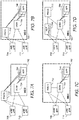
- FIGs. 7A, 7B, 7C, and 7D are block diagrams of alternative embodiments of the system in a mobile edge computing (MEC) environment.
- the distributed gateway (DGW) 704 is located in the edge along with traffic source applications 706.
- the eNBs/gNBs 708 and 710 perform the functions of the BBUs with a NCP node as described above with reference to FIG. 4A .
- the eNBs/GNBs 708 and 710 receive parameters describing information to be gathered from the data flows provided to the UEs (not shown in FIG. 7A ) and provides this information to the PINCS node 712.
- the PINCS node 712 is not co-located with the MEC server 702.
- the PINCS node 712 may be located in a separate enclosure within the same facility or at the CN or other location remote from the MEC server.
- the PINCS node 712 provides the network condition information to the APPs 706, which use the information to implement the network control functions. This embodiment corresponds to the direct mode, described above with reference to FIGS. 4A-4D .
- the embodiment shown in FIG. 7B also implements the direct mode. It differs from the embodiment shown in FIG. 7A in that the PINCS node 712 is located at the edge, with the MEC server 742. In the embodiment of FIG. 7B , the hardware used to implement the PINCS node 712 may consume valuable space in the MEC enclosure. Thus, the embodiment in FIG. 7A may be preferential where space at the edge is limited.
- the example embodiment shown in FIG. 7D differs from the embodiment of FIG. 7C by the addition of the NCP prober 764.
- the eNB/gNBs 708 and 710 are not modified to include the NCP functionality. Instead, the NCP prober 764 interacts with the eNBs/gNBs 708 and 710 to obtain the requested network condition data.
- the NCP prober 764 may send status request messages to the eNBs/gNBs 708, 710 to obtain the information or may send null packets to the UE devices through the eNBs/gNBs 708 and 710 and monitor the resulting ACK packets to determine latency and bandwidth.
- the NCP information generated by the prober 764 is provided to the PINCS node 712 which, in turn, provides subscribed information to the DGW/NCC node 704.
- the network condition information is provided by the DGW/NCC node 704, which sends the network condition information to the APPs 706 using in-line signaling to implement the network control functions.
- the NCP nodes described above provide network condition information that may include more than queue length and bandwidth because queue length and bandwidth may not reflect delays caused by scheduling at the BBU. For example, a queue having a length of 10 packets may experience more delay when there are many active users than when there are few active users and thus, no competition for the queue.
- measurements made by from BBU are sent to another entity - the PINCS node - to be processed.
- Processing the measurements provided by the BBU in the PINCS node avoids adding extra functionality in the BBU and thus avoids incurring additional processing delay due to the added functionality.
- FIG. 8 is a block diagram of example processing circuitry for clients, servers, and cloud based processing system resources for implementing algorithms and performing methods according to example embodiments.
- the distributed processing system may include multiple instances of the circuitry shown in FIG. 8 which may be used to implement any of the elements/nodes shown in FIGs. 2 , 3 , 4A , 5A , 6 , and/or 7. All components need not be used in various embodiments.
- each of the clients, servers, and network resources of the distributed processing system may each use a different set of components, or in the case of servers or mainframes, for example, larger storage devices.
- the storage may also or alternatively include cloud-based storage accessible via a network, such as a local area network (LAN), a personal area network, (PAN) a wide area network (WAN) such as the Internet, or local server based storage.
- a network such as a local area network (LAN), a personal area network, (PAN) a wide area network (WAN) such as the Internet, or local server based storage.
- LAN local area network
- PAN personal area network
- WAN wide area network
- the Internet or local server based storage.
- Memory 803 may include volatile memory 814 and non-volatile memory 808.
- Computer 800 may include - or have access to a processing environment that includes - a variety of computer-readable media, such as volatile memory 814 and non-volatile memory 808, removable storage 810 and non-removable storage 812.
- Computer storage includes random access memory (RAM), read only memory (ROM), erasable programmable read-only memory (EPROM), electrically erasable programmable read-only memory (EEPROM), flash memory or other memory technologies, compact disc read-only memory (CD ROM), digital versatile disks (DVD) or other optical disk storage, magnetic cassettes, magnetic tape, magnetic disk storage or other magnetic storage devices, or any other medium capable of storing computer-readable instructions.
- Computer 800 may include or have access to a processing environment that includes input interface 806, output interface 804, and a communication connection or interface 816, also communicatively coupled to the bus 801.
- Output interface 804 may include a display device, such as a touchscreen, that also may serve as an input device coupled to the input interface 806.
- the input interface 806 may include one or more of a touchscreen, touchpad, mouse, keyboard, camera, one or more device-specific buttons, one or more sensors integrated within or coupled via wired or wireless data connections to the processing system 800, and other input devices.
- the computer 800 may operate in a networked environment using a communication connection to connect to one or more remote computers, such as mainframes and/or database servers.
- the remote computer may include a personal computer (PC), server, router, network PC, a peer device or other common network node, or the like.
- the communication connection may include a local area network (LAN), a wide area network (WAN), cellular, Wi-Fi, Bluetooth, or other networks.
- Computer-readable instructions or applications 818 stored on a computer-readable medium are executable by the processing unit 802 of the computer 800.
- a hard drive, CD-ROM, and RAM are some examples of articles including a non-transitory computer-readable medium such as a storage device.
- the terms computer-readable medium and storage device do not include carrier waves to the extent carrier waves are deemed too transitory.
- one or more applications 818 may be used to cause processing unit 802 to perform one or more methods or algorithms described herein.
- the computer 800 includes a subscription reception module receiving a subscription for network condition information of at least one network from at least one network condition consumer (NCC) node, the network condition information being related to at least one target data flow provided to at least one node in the network via the NCC node, an information obtaining module obtaining information about a plurality of network conditions from at least one network condition provider (NCP) node configured to monitor a plurality of network conditions including network conditions related to the at least one target data flow, an information processing module processing the information about the plurality of network conditions to generate an aggregated network conditions information, and a send module sending the aggregated network conditions information the NCC node as indicated by the subscription.
- the computer 800 may include other or additional modules for performing any one of or combination of steps described in the embodiments.
Landscapes
- Engineering & Computer Science (AREA)
- Computer Networks & Wireless Communication (AREA)
- Signal Processing (AREA)
- Physics & Mathematics (AREA)
- Mathematical Physics (AREA)
- Theoretical Computer Science (AREA)
- Mobile Radio Communication Systems (AREA)
- Data Exchanges In Wide-Area Networks (AREA)
Claims (14)
- Einrichtung für einen protokollunabhängigen Netzwerkbedingungsdienst (Protocol Independent Network Condition Service - PINCS) (310), die Folgendes umfasst:• einen nicht flüchtigen Speicher, der Anweisungen umfasst; und• einen oder mehrere Prozessoren in Kommunikation mit dem Speicher, wobei die Anweisungen, wenn sie durch den einen oder die mehreren Prozessoren ausgeführt werden, die PINCS-Einrichtung (310) zu Folgendem veranlassen:∘ Empfangen eines Abonnements für Netzwerkbedingungsinformationen wenigstens eines Netzwerks von wenigstens einem Netzwerkbedingungsverbraucher(Network Condition Consumer- NCC)-Knoten (306), wobei die Netzwerkbedingungsinformationen sich auf wenigstens einen Zieldatenfluss beziehen, der über den NCC-Knoten (306) wenigstens einem Knoten in dem Netzwerk bereitgestellt wird,
wobei die Netzwerkbedingungsinformationen Folgendes beinhalten:▪ eine Funkbandbreite,▪ eine Trägerwarteschlangenlänge,▪ eine Flusswarteschlangenlänge,▪ eine Trägerwarteschlangenerschöpfungsrate, und/oder▪ eine Flusswarteschlangenerschöpfungsrate;∘ Erhalten der Netzwerkbedingungsinformationen von wenigstens einem Netzwerkbedingungsanbieter(Network Condition Provider - NCP)-Knoten (304) der konfiguriert ist, um mehrere Netzwerkbedingungen zu überwachen, die Netzwerkbedingungen beinhalten, die sich auf den wenigstens einen Zieldatenfluss beziehen;∘ Verarbeiten der Netzwerkbedingungsinformationen, um aggregierte Netzwerkbedingungsinformationen zu erzeugen; und∘ Senden der aggregierten Netzwerkbedingungsinformationen an den NCC-Knoten (306), wie durch das Abonnement angegeben. - PINCS-Einrichtung nach Anspruch 1, wobei die Netzwerkbedingungsinformationen Informationen bezüglich mehrerer Datenflüsse beinhalten, die den wenigstens einen Zieldatenfluss beinhalten, wobei die mehreren Datenflüsse gemäß mehreren Protokollen arbeiten.
- PINCS-Einrichtung nach einem der Ansprüche 1 bis 2, wobei die Anweisungen, wenn sie durch den einen oder die mehreren Prozessoren ausgeführt werden, die PINCS-Einrichtung ferner zu Folgendem veranlassen: Empfangen jeweiliger Abonnements von mehreren NCC-Knoten, die sich auf jeweilige mehrere Datenflüsse beziehen und Empfangen der Netzwerkbedingungsinformationen von mehreren Netzwerkbedingungsanbietern.
- PINCS-Einrichtung nach einem der Ansprüche 1 bis 3, wobei die PINCS-Einrichtung eine Komponente einer Netzwerkexpositionsfunktion eines Systems der fünften Generation (5G) ist.
- PINCS-Einrichtung nach einem der Ansprüche 1 bis 4, wobei die PINCS-Einrichtung mit einem mobilen Edge-Computing(MEC)-System gekoppelt ist, das einen MEC-Server beinhaltet, und wobei sich die PINCS-Einrichtung und der MEC-Server an getrennten Orten befinden.
- PINCS-Vorrichtung nach einem der Ansprüche 1 bis 4, wobei die PINCS-Einrichtung mit einem mobilen Edge-Computing(MEC)-System gekoppelt ist, das einen MEC-Server beinhaltet, und wobei die PINCS-Einrichtung und der MEC-Server sich an einem gemeinsamen Ort befinden.
- PINCS-Einrichtung nach einem der Ansprüche 1 bis 6, wobei die PINCS-Einrichtung konfiguriert ist, um Nebeninformationen von einem Knoten B zu empfangen, wie etwa eine Funkkanal- und Dienstgüte(Quality of Service - QoS)-bewusste Segmentierung der momentanen Zellenkapazität und eine S1 Schnittstelle, Durchsatz, Verlust, Warteschlangenlänge, durchschnittliche Warteschlangenerschöpfungsrate und Verzögerung.
- Netzwerkbedingungsverbraucher(NCC)-Einrichtung (306), die Folgendes umfasst:• einen nicht flüchtigen Speicher, der Anweisungen umfasst; und• einen oder mehrere Prozessoren in Kommunikation mit dem Speicher, wobei die Anweisungen, wenn sie durch den einen oder die mehreren Prozessoren ausgeführt werden, die NCC-Einrichtung veranlassen, die Anweisungen zu Folgendem auszuführen:∘ Senden eines Abonnements für Netzwerkbedingungsinformationen wenigstens eines Netzwerks an einen protokollunabhängigen Netzwerkbedingungsdienst(PINCS)-Knoten (310), wobei sich die Netzwerkbedingungsinformationen auf wenigstens einen Zieldatenfluss beziehen, der wenigstens einem Knoten in dem Netzwerk bereitgestellt wird,
wobei die Netzwerkbedingungsinformationen Folgendes beinhalten:▪ eine Funkbandbreite,▪ eine Trägerwarteschlangenlänge,▪ eine Flusswarteschlangenlänge,▪ eine Trägerwarteschlangenerschöpfungsrate, und/oder▪ eine Flusswarteschlangenerschöpfungsrate;∘ Erhalten der Netzwerkbedingungsinformationen von dem PINCS-Knoten (310), wie in dem Abonnement angegeben; und∘ Anwenden der Netzwerkbedingungsinformationen, um eine Netzwerküberlastung zu steuern und eine Latenz für den Zieldatenfluss von einem Quellknoten zu reduzieren, der mit der NCC-Einrichtung (306) gekoppelt ist. - NCC-Einrichtung nach Anspruch 8, wobei die NCC-Einrichtung mit dem Quellknoten angeordnet ist und das Verarbeitungssystem konfiguriert ist, um die Überlastungssteuerung in dem Netzwerktransport zu implementieren.
- NCC-Einrichtung nach Anspruch 8, wobei die NCC-Einrichtung von dem Quellknoten getrennt ist und die NCC-Einrichtung konfiguriert ist, um die Netzwerkbedingungsinformationen unter Verwendung einer Inband-Signalisierung an den Quellknoten zu senden.
- NCC-Einrichtung nach einem der Ansprüche 8 bis 10, wobei die NCC-Einrichtung konfiguriert ist, um eine Ratensteuerung zu implementieren.
- NCC-Einrichtung nach einem der Ansprüche 8 bis 11, wobei die NCC-Einrichtung konfiguriert ist, um eine Puffersteuerung zu implementieren.
- Netzwerkbedingungsanbieter(NCP)-Einrichtung (304), die Folgendes umfasst:• einen nicht flüchtigen Speicher, der Anweisungen umfasst; und• einen oder mehrere Prozessoren in Kommunikation mit dem Speicher, wobei die Anweisungen, wenn sie durch den einen oder die mehreren Prozessoren ausgeführt werden, die NCP-Einrichtung zu Folgendem veranlassen:∘ periodisches Erhalten von Netzwerkbedingungsinformationen über mehrere Datenflüsse, die einer oder mehreren UE-Vorrichtungen von einer Funkzugangsnetzwerk(Radio Access Network - RAN)-Vorrichtung bereitgestellt werden,
wobei die Netzwerkbedingungsinformationen Folgendes beinhalten:▪ eine Funkbandbreite,▪ eine Trägerwarteschlangenlänge,▪ eine Flusswarteschlangenlänge,▪ eine Trägerwarteschlangenerschöpfungsrate, und/oder▪ eine Flusswarteschlangenerschöpfungsrate;∘ Empfangen, von einem protokollunabhängigen Netzwerkbedingungsdienst(PINCS)-Knoten (310), einer Anforderung von Informationen über Netzwerkbedingungen, die sich auf wenigstens einen Fluss der mehreren Datenflüsse beziehen;∘ periodisches Senden der angeforderten Informationen über die Netzwerkbedingungen an den PINCS-Knoten (310), wobei die Informationen über die Netzwerkbedingungen Informationen unter den periodisch erhaltenen Netzwerkbedingungsinformationen sind. - Verfahren zum Implementieren eines protokollunabhängigen Netzwerkbedingungsdienstes (PINCS), durchgeführt durch eine PINCS-Einrichtung (310) nach Anspruch 1, wobei das Verfahren Folgendes umfasst:∘ Empfangen eines Abonnements für Netzwerkbedingungsinformationen wenigstens eines Netzwerks von wenigstens einem Netzwerkbedingungsverbraucher(NCC)-Knoten (306), wobei sich die Netzwerkbedingungsinformationen auf wenigstens einen Zieldatenfluss beziehen, der wenigstens einem Knoten in dem Netzwerk über den NCC-Knoten (306) bereitgestellt wird,
wobei die Netzwerkbedingungsinformationen Folgendes beinhalten:▪ eine Funkbandbreite,▪ eine Trägerwarteschlangenlänge,▪ eine Flusswarteschlangenlänge,▪ eine Trägerwarteschlangenerschöpfungsrate, und/oder▪ eine Flusswarteschlangenerschöpfungsrate;∘ Erhalten der Netzwerkbedingungsinformationen von wenigstens einem Netzwerkbedingungsanbieter(NCP)-Knoten (304), der konfiguriert ist, um mehrere Netzwerkbedingungen zu überwachen, die Netzwerkbedingungen beinhalten, die sich auf den wenigstens einen Zieldatenfluss beziehen;∘ Verarbeiten der Netzwerkbedingungsinformationen, um aggregierte Netzwerkbedingungsinformationen zu erzeugen; und∘ Senden der aggregierten Netzwerkbedingungsinformationen an den NCC-Knoten (306), wie durch das Abonnement angegeben.
Applications Claiming Priority (2)
| Application Number | Priority Date | Filing Date | Title |
|---|---|---|---|
| US15/796,183 US10674394B2 (en) | 2017-10-27 | 2017-10-27 | Method and apparatus for reducing network latency |
| PCT/CN2018/111197 WO2019080794A1 (en) | 2017-10-27 | 2018-10-22 | METHOD AND APPARATUS FOR REDUCING THE LATENCY OF A NETWORK |
Publications (3)
| Publication Number | Publication Date |
|---|---|
| EP3669575A1 EP3669575A1 (de) | 2020-06-24 |
| EP3669575A4 EP3669575A4 (de) | 2020-08-19 |
| EP3669575B1 true EP3669575B1 (de) | 2021-09-29 |
Family
ID=66245786
Family Applications (1)
| Application Number | Title | Priority Date | Filing Date |
|---|---|---|---|
| EP18870532.1A Not-in-force EP3669575B1 (de) | 2017-10-27 | 2018-10-22 | Verfahren und vorrichtungen zur reduzierung der netzwerklatenz |
Country Status (4)
| Country | Link |
|---|---|
| US (1) | US10674394B2 (de) |
| EP (1) | EP3669575B1 (de) |
| CN (1) | CN111034254B (de) |
| WO (1) | WO2019080794A1 (de) |
Families Citing this family (14)
| Publication number | Priority date | Publication date | Assignee | Title |
|---|---|---|---|---|
| CN112205007B (zh) * | 2018-06-01 | 2022-11-01 | 三星电子株式会社 | 利用启用层在5g网络中更好地利用资源的系统和方法 |
| US11076027B1 (en) * | 2018-12-03 | 2021-07-27 | Amazon Technologies, Inc. | Network communications protocol selection based on network topology or performance |
| US10728138B2 (en) * | 2018-12-21 | 2020-07-28 | At&T Intellectual Property I, L.P. | Analytics enabled radio access network (RAN)- aware content optimization using mobile edge computing |
| US11234157B2 (en) * | 2019-04-08 | 2022-01-25 | T-Mobile Usa, Inc. | Network latency aware mobile edge computing routing |
| CN112153555B (zh) * | 2019-06-28 | 2023-07-21 | 中兴通讯股份有限公司 | 媒体服务在区域间的切换方法、服务器、系统及存储介质 |
| CN111865697B (zh) * | 2020-07-29 | 2021-09-24 | 广东电网有限责任公司电力调度控制中心 | 配用电系统边缘计算终端的计算负荷表征方法及装置 |
| US11848868B2 (en) | 2021-09-29 | 2023-12-19 | Huawei Technologies Co., Ltd. | Methods, systems and devices for network management using control packets |
| US12217174B2 (en) * | 2021-10-19 | 2025-02-04 | Volvo Car Corporation | Intelligent messaging framework for vehicle ecosystem communication |
| CN114221886B (zh) * | 2021-12-21 | 2023-05-12 | 杭州米络星科技(集团)有限公司 | 一种数据传输方法、装置、流媒体服务器及发送客户端 |
| US11863451B2 (en) | 2022-05-16 | 2024-01-02 | Huawei Technologies Co., Ltd. | Hardware accelerated temporal congestion signals |
| CN121925830A (zh) * | 2024-08-09 | 2026-04-24 | 新华三技术有限公司 | 一种报文处理、资源管理方法、装置及设备 |
| CN119135609B (zh) * | 2024-09-05 | 2025-11-07 | 新华三技术有限公司 | 通信系统、资源管理方法及装置 |
| CN121772002A (zh) * | 2024-09-30 | 2026-03-31 | 维沃移动通信有限公司 | 速率控制方法、终端及网络侧设备 |
| CN118984469B (zh) * | 2024-10-17 | 2024-12-20 | 成都乐超人科技有限公司 | 基于大数据结合5g技术下的边缘通信方法及系统 |
Family Cites Families (17)
| Publication number | Priority date | Publication date | Assignee | Title |
|---|---|---|---|---|
| MY139033A (en) * | 2002-05-01 | 2009-08-28 | Interdigital Tech Corp | Point to multi-point services using shared channels in wireless communication systems |
| JP4658098B2 (ja) * | 2006-11-21 | 2011-03-23 | 日本電信電話株式会社 | フロー情報制限装置および方法 |
| CN101014045B (zh) * | 2007-02-02 | 2010-09-01 | 清华大学 | 服务承载网中服务管理的分布式方法 |
| CN102404187A (zh) | 2010-09-13 | 2012-04-04 | 华为技术有限公司 | 拥塞控制方法和系统以及网络设备 |
| US8976655B2 (en) * | 2010-09-16 | 2015-03-10 | Vasona Networks Inc. | Evaluating a capacity of a cell of a radio access network |
| HUE035467T2 (en) * | 2013-06-28 | 2018-05-02 | Ericsson Telefon Ab L M | Procedures and Equipment for Controlling Data Package Process to Reset Radio Base Station Excessive Buffer Time |
| CN104518967B (zh) * | 2013-09-30 | 2017-12-12 | 华为技术有限公司 | 路由方法、设备和系统 |
| TWI538441B (zh) * | 2013-11-05 | 2016-06-11 | 衛信科技有限公司 | 用以建構網路結構部署圖之處理系統及其方法與內儲網路結構部署分析程式之電腦程式產品 |
| CN104734872B (zh) | 2013-12-19 | 2018-02-23 | 中国科学院沈阳自动化研究所 | 一种基于软件定义网络的工业回程网实现方法与系统 |
| CN105897584B (zh) * | 2014-06-09 | 2018-11-30 | 华为技术有限公司 | 路径规划方法和控制器 |
| KR102196492B1 (ko) * | 2014-07-04 | 2020-12-30 | 삼성전자주식회사 | 통신 시스템에서 데이터 송수신 장치 및 방법 |
| CN104125159B (zh) | 2014-07-29 | 2017-09-12 | 福建星网锐捷网络有限公司 | 一种拥塞带宽检测方法、装置及系统 |
| US9860788B2 (en) * | 2014-12-03 | 2018-01-02 | At&T Intellectual Property I, L.P. | Reconfiguring mobile services based on shared control signaling load information |
| US9998565B2 (en) * | 2015-05-25 | 2018-06-12 | Juniper Networks, Inc. | Selecting and monitoring a plurality of services key performance indicators using TWAMP |
| CN105515831A (zh) * | 2015-11-27 | 2016-04-20 | 小米科技有限责任公司 | 网络状态信息展示方法及装置 |
| US10142185B2 (en) * | 2016-06-08 | 2018-11-27 | At&T Intellectual Property I, L.P. | Content quality assessment and prediction via flows |
| CN108092791B (zh) * | 2016-11-23 | 2020-06-16 | 华为技术有限公司 | 网络控制方法、装置及系统 |
-
2017
- 2017-10-27 US US15/796,183 patent/US10674394B2/en not_active Expired - Fee Related
-
2018
- 2018-10-22 CN CN201880054210.5A patent/CN111034254B/zh not_active Expired - Fee Related
- 2018-10-22 EP EP18870532.1A patent/EP3669575B1/de not_active Not-in-force
- 2018-10-22 WO PCT/CN2018/111197 patent/WO2019080794A1/en not_active Ceased
Also Published As
| Publication number | Publication date |
|---|---|
| US20190132767A1 (en) | 2019-05-02 |
| CN111034254B (zh) | 2021-08-20 |
| WO2019080794A1 (en) | 2019-05-02 |
| US10674394B2 (en) | 2020-06-02 |
| CN111034254A (zh) | 2020-04-17 |
| EP3669575A1 (de) | 2020-06-24 |
| EP3669575A4 (de) | 2020-08-19 |
Similar Documents
| Publication | Publication Date | Title |
|---|---|---|
| US10674394B2 (en) | Method and apparatus for reducing network latency | |
| EP3939225B1 (de) | Ermöglichung des echtzeittransports von datenströmen | |
| CN108141443B (zh) | 用户设备、媒体流传输网络辅助节点和媒体流传输方法 | |
| JP2023002774A (ja) | パケット伝送システムおよび方法 | |
| CN106797348B (zh) | 基于用户平面洞察力的吞吐量指导 | |
| EP3235177B1 (de) | Messkoordination in der kommunikation | |
| US8385221B2 (en) | System and method for monitoring of user quality-of-experience on a wireless network | |
| US9596323B2 (en) | Transport accelerator implementing client side transmission functionality | |
| CN108141779A (zh) | 用于通信网络的方法和设备 | |
| WO2021089487A1 (en) | Method and apparatus for transmitting real-time media stream | |
| US10972778B2 (en) | Stream control system for use in a network | |
| US10812546B2 (en) | Link-aware streaming adaptation | |
| US11218910B2 (en) | First node and a second node and methods of operating the same | |
| US10868839B2 (en) | Method and system for upload optimization | |
| US11695847B2 (en) | Throughput guidance based on user plane insight | |
| Yang et al. | APCC: Active Precise Congestion Control for Campus Wireless Networks | |
| KR20210077841A (ko) | 고품질 저지연 실시간 미디어 스트리밍 서비스를 제공하는 방법 및 그 장치 | |
| WO2018171868A1 (en) | Controlling downstream flow of data packets via a ran | |
| JP6645931B2 (ja) | QoS制御システム及び方法 |
Legal Events
| Date | Code | Title | Description |
|---|---|---|---|
| STAA | Information on the status of an ep patent application or granted ep patent |
Free format text: STATUS: THE INTERNATIONAL PUBLICATION HAS BEEN MADE |
|
| PUAI | Public reference made under article 153(3) epc to a published international application that has entered the european phase |
Free format text: ORIGINAL CODE: 0009012 |
|
| STAA | Information on the status of an ep patent application or granted ep patent |
Free format text: STATUS: REQUEST FOR EXAMINATION WAS MADE |
|
| 17P | Request for examination filed |
Effective date: 20200317 |
|
| AK | Designated contracting states |
Kind code of ref document: A1 Designated state(s): AL AT BE BG CH CY CZ DE DK EE ES FI FR GB GR HR HU IE IS IT LI LT LU LV MC MK MT NL NO PL PT RO RS SE SI SK SM TR |
|
| AX | Request for extension of the european patent |
Extension state: BA ME |
|
| REG | Reference to a national code |
Ref country code: DE Ref legal event code: R079 Ref document number: 602018024451 Country of ref document: DE Free format text: PREVIOUS MAIN CLASS: H04W0028100000 Ipc: H04W0024080000 |
|
| A4 | Supplementary search report drawn up and despatched |
Effective date: 20200722 |
|
| RIC1 | Information provided on ipc code assigned before grant |
Ipc: H04W 24/08 20090101AFI20200716BHEP Ipc: H04W 28/02 20090101ALI20200716BHEP |
|
| DAV | Request for validation of the european patent (deleted) | ||
| DAX | Request for extension of the european patent (deleted) | ||
| GRAP | Despatch of communication of intention to grant a patent |
Free format text: ORIGINAL CODE: EPIDOSNIGR1 |
|
| STAA | Information on the status of an ep patent application or granted ep patent |
Free format text: STATUS: GRANT OF PATENT IS INTENDED |
|
| INTG | Intention to grant announced |
Effective date: 20210420 |
|
| GRAS | Grant fee paid |
Free format text: ORIGINAL CODE: EPIDOSNIGR3 |
|
| GRAA | (expected) grant |
Free format text: ORIGINAL CODE: 0009210 |
|
| STAA | Information on the status of an ep patent application or granted ep patent |
Free format text: STATUS: THE PATENT HAS BEEN GRANTED |
|
| AK | Designated contracting states |
Kind code of ref document: B1 Designated state(s): AL AT BE BG CH CY CZ DE DK EE ES FI FR GB GR HR HU IE IS IT LI LT LU LV MC MK MT NL NO PL PT RO RS SE SI SK SM TR |
|
| REG | Reference to a national code |
Ref country code: GB Ref legal event code: FG4D |
|
| REG | Reference to a national code |
Ref country code: CH Ref legal event code: EP Ref country code: AT Ref legal event code: REF Ref document number: 1435329 Country of ref document: AT Kind code of ref document: T Effective date: 20211015 |
|
| REG | Reference to a national code |
Ref country code: DE Ref legal event code: R096 Ref document number: 602018024451 Country of ref document: DE |
|
| REG | Reference to a national code |
Ref country code: IE Ref legal event code: FG4D |
|
| REG | Reference to a national code |
Ref country code: LT Ref legal event code: MG9D |
|
| PG25 | Lapsed in a contracting state [announced via postgrant information from national office to epo] |
Ref country code: SE Free format text: LAPSE BECAUSE OF FAILURE TO SUBMIT A TRANSLATION OF THE DESCRIPTION OR TO PAY THE FEE WITHIN THE PRESCRIBED TIME-LIMIT Effective date: 20210929 Ref country code: RS Free format text: LAPSE BECAUSE OF FAILURE TO SUBMIT A TRANSLATION OF THE DESCRIPTION OR TO PAY THE FEE WITHIN THE PRESCRIBED TIME-LIMIT Effective date: 20210929 Ref country code: FI Free format text: LAPSE BECAUSE OF FAILURE TO SUBMIT A TRANSLATION OF THE DESCRIPTION OR TO PAY THE FEE WITHIN THE PRESCRIBED TIME-LIMIT Effective date: 20210929 Ref country code: BG Free format text: LAPSE BECAUSE OF FAILURE TO SUBMIT A TRANSLATION OF THE DESCRIPTION OR TO PAY THE FEE WITHIN THE PRESCRIBED TIME-LIMIT Effective date: 20211229 Ref country code: LT Free format text: LAPSE BECAUSE OF FAILURE TO SUBMIT A TRANSLATION OF THE DESCRIPTION OR TO PAY THE FEE WITHIN THE PRESCRIBED TIME-LIMIT Effective date: 20210929 Ref country code: NO Free format text: LAPSE BECAUSE OF FAILURE TO SUBMIT A TRANSLATION OF THE DESCRIPTION OR TO PAY THE FEE WITHIN THE PRESCRIBED TIME-LIMIT Effective date: 20211229 Ref country code: HR Free format text: LAPSE BECAUSE OF FAILURE TO SUBMIT A TRANSLATION OF THE DESCRIPTION OR TO PAY THE FEE WITHIN THE PRESCRIBED TIME-LIMIT Effective date: 20210929 |
|
| REG | Reference to a national code |
Ref country code: NL Ref legal event code: MP Effective date: 20210929 |
|
| REG | Reference to a national code |
Ref country code: AT Ref legal event code: MK05 Ref document number: 1435329 Country of ref document: AT Kind code of ref document: T Effective date: 20210929 |
|
| PG25 | Lapsed in a contracting state [announced via postgrant information from national office to epo] |
Ref country code: LV Free format text: LAPSE BECAUSE OF FAILURE TO SUBMIT A TRANSLATION OF THE DESCRIPTION OR TO PAY THE FEE WITHIN THE PRESCRIBED TIME-LIMIT Effective date: 20210929 Ref country code: GR Free format text: LAPSE BECAUSE OF FAILURE TO SUBMIT A TRANSLATION OF THE DESCRIPTION OR TO PAY THE FEE WITHIN THE PRESCRIBED TIME-LIMIT Effective date: 20211230 |
|
| PG25 | Lapsed in a contracting state [announced via postgrant information from national office to epo] |
Ref country code: AT Free format text: LAPSE BECAUSE OF FAILURE TO SUBMIT A TRANSLATION OF THE DESCRIPTION OR TO PAY THE FEE WITHIN THE PRESCRIBED TIME-LIMIT Effective date: 20210929 |
|
| REG | Reference to a national code |
Ref country code: CH Ref legal event code: PL |
|
| PG25 | Lapsed in a contracting state [announced via postgrant information from national office to epo] |
Ref country code: IS Free format text: LAPSE BECAUSE OF FAILURE TO SUBMIT A TRANSLATION OF THE DESCRIPTION OR TO PAY THE FEE WITHIN THE PRESCRIBED TIME-LIMIT Effective date: 20220129 Ref country code: SK Free format text: LAPSE BECAUSE OF FAILURE TO SUBMIT A TRANSLATION OF THE DESCRIPTION OR TO PAY THE FEE WITHIN THE PRESCRIBED TIME-LIMIT Effective date: 20210929 Ref country code: RO Free format text: LAPSE BECAUSE OF FAILURE TO SUBMIT A TRANSLATION OF THE DESCRIPTION OR TO PAY THE FEE WITHIN THE PRESCRIBED TIME-LIMIT Effective date: 20210929 Ref country code: PT Free format text: LAPSE BECAUSE OF FAILURE TO SUBMIT A TRANSLATION OF THE DESCRIPTION OR TO PAY THE FEE WITHIN THE PRESCRIBED TIME-LIMIT Effective date: 20220131 Ref country code: PL Free format text: LAPSE BECAUSE OF FAILURE TO SUBMIT A TRANSLATION OF THE DESCRIPTION OR TO PAY THE FEE WITHIN THE PRESCRIBED TIME-LIMIT Effective date: 20210929 Ref country code: NL Free format text: LAPSE BECAUSE OF FAILURE TO SUBMIT A TRANSLATION OF THE DESCRIPTION OR TO PAY THE FEE WITHIN THE PRESCRIBED TIME-LIMIT Effective date: 20210929 Ref country code: ES Free format text: LAPSE BECAUSE OF FAILURE TO SUBMIT A TRANSLATION OF THE DESCRIPTION OR TO PAY THE FEE WITHIN THE PRESCRIBED TIME-LIMIT Effective date: 20210929 Ref country code: EE Free format text: LAPSE BECAUSE OF FAILURE TO SUBMIT A TRANSLATION OF THE DESCRIPTION OR TO PAY THE FEE WITHIN THE PRESCRIBED TIME-LIMIT Effective date: 20210929 Ref country code: CZ Free format text: LAPSE BECAUSE OF FAILURE TO SUBMIT A TRANSLATION OF THE DESCRIPTION OR TO PAY THE FEE WITHIN THE PRESCRIBED TIME-LIMIT Effective date: 20210929 Ref country code: AL Free format text: LAPSE BECAUSE OF FAILURE TO SUBMIT A TRANSLATION OF THE DESCRIPTION OR TO PAY THE FEE WITHIN THE PRESCRIBED TIME-LIMIT Effective date: 20210929 |
|
| REG | Reference to a national code |
Ref country code: BE Ref legal event code: MM Effective date: 20211031 |
|
| PG25 | Lapsed in a contracting state [announced via postgrant information from national office to epo] |
Ref country code: MC Free format text: LAPSE BECAUSE OF FAILURE TO SUBMIT A TRANSLATION OF THE DESCRIPTION OR TO PAY THE FEE WITHIN THE PRESCRIBED TIME-LIMIT Effective date: 20210929 |
|
| REG | Reference to a national code |
Ref country code: DE Ref legal event code: R097 Ref document number: 602018024451 Country of ref document: DE |
|
| PG25 | Lapsed in a contracting state [announced via postgrant information from national office to epo] |
Ref country code: LU Free format text: LAPSE BECAUSE OF NON-PAYMENT OF DUE FEES Effective date: 20211022 Ref country code: DK Free format text: LAPSE BECAUSE OF FAILURE TO SUBMIT A TRANSLATION OF THE DESCRIPTION OR TO PAY THE FEE WITHIN THE PRESCRIBED TIME-LIMIT Effective date: 20210929 Ref country code: BE Free format text: LAPSE BECAUSE OF NON-PAYMENT OF DUE FEES Effective date: 20211031 |
|
| PLBE | No opposition filed within time limit |
Free format text: ORIGINAL CODE: 0009261 |
|
| STAA | Information on the status of an ep patent application or granted ep patent |
Free format text: STATUS: NO OPPOSITION FILED WITHIN TIME LIMIT |
|
| PG25 | Lapsed in a contracting state [announced via postgrant information from national office to epo] |
Ref country code: LI Free format text: LAPSE BECAUSE OF NON-PAYMENT OF DUE FEES Effective date: 20211031 Ref country code: CH Free format text: LAPSE BECAUSE OF NON-PAYMENT OF DUE FEES Effective date: 20211031 |
|
| 26N | No opposition filed |
Effective date: 20220630 |
|
| PG25 | Lapsed in a contracting state [announced via postgrant information from national office to epo] |
Ref country code: IE Free format text: LAPSE BECAUSE OF NON-PAYMENT OF DUE FEES Effective date: 20211022 |
|
| PG25 | Lapsed in a contracting state [announced via postgrant information from national office to epo] |
Ref country code: SI Free format text: LAPSE BECAUSE OF FAILURE TO SUBMIT A TRANSLATION OF THE DESCRIPTION OR TO PAY THE FEE WITHIN THE PRESCRIBED TIME-LIMIT Effective date: 20210929 Ref country code: FR Free format text: LAPSE BECAUSE OF NON-PAYMENT OF DUE FEES Effective date: 20211129 |
|
| PG25 | Lapsed in a contracting state [announced via postgrant information from national office to epo] |
Ref country code: IT Free format text: LAPSE BECAUSE OF FAILURE TO SUBMIT A TRANSLATION OF THE DESCRIPTION OR TO PAY THE FEE WITHIN THE PRESCRIBED TIME-LIMIT Effective date: 20210929 |
|
| PG25 | Lapsed in a contracting state [announced via postgrant information from national office to epo] |
Ref country code: CY Free format text: LAPSE BECAUSE OF FAILURE TO SUBMIT A TRANSLATION OF THE DESCRIPTION OR TO PAY THE FEE WITHIN THE PRESCRIBED TIME-LIMIT Effective date: 20210929 |
|
| PG25 | Lapsed in a contracting state [announced via postgrant information from national office to epo] |
Ref country code: SM Free format text: LAPSE BECAUSE OF FAILURE TO SUBMIT A TRANSLATION OF THE DESCRIPTION OR TO PAY THE FEE WITHIN THE PRESCRIBED TIME-LIMIT Effective date: 20210929 Ref country code: HU Free format text: LAPSE BECAUSE OF FAILURE TO SUBMIT A TRANSLATION OF THE DESCRIPTION OR TO PAY THE FEE WITHIN THE PRESCRIBED TIME-LIMIT; INVALID AB INITIO Effective date: 20181022 |
|
| PGFP | Annual fee paid to national office [announced via postgrant information from national office to epo] |
Ref country code: GB Payment date: 20230831 Year of fee payment: 6 |
|
| PGFP | Annual fee paid to national office [announced via postgrant information from national office to epo] |
Ref country code: DE Payment date: 20230830 Year of fee payment: 6 |
|
| PG25 | Lapsed in a contracting state [announced via postgrant information from national office to epo] |
Ref country code: MK Free format text: LAPSE BECAUSE OF FAILURE TO SUBMIT A TRANSLATION OF THE DESCRIPTION OR TO PAY THE FEE WITHIN THE PRESCRIBED TIME-LIMIT Effective date: 20210929 |
|
| PG25 | Lapsed in a contracting state [announced via postgrant information from national office to epo] |
Ref country code: MT Free format text: LAPSE BECAUSE OF FAILURE TO SUBMIT A TRANSLATION OF THE DESCRIPTION OR TO PAY THE FEE WITHIN THE PRESCRIBED TIME-LIMIT Effective date: 20210929 |
|
| REG | Reference to a national code |
Ref country code: DE Ref legal event code: R119 Ref document number: 602018024451 Country of ref document: DE |
|
| GBPC | Gb: european patent ceased through non-payment of renewal fee |
Effective date: 20241022 |
|
| PG25 | Lapsed in a contracting state [announced via postgrant information from national office to epo] |
Ref country code: DE Free format text: LAPSE BECAUSE OF NON-PAYMENT OF DUE FEES Effective date: 20250501 |
|
| PG25 | Lapsed in a contracting state [announced via postgrant information from national office to epo] |
Ref country code: GB Free format text: LAPSE BECAUSE OF NON-PAYMENT OF DUE FEES Effective date: 20241022 |
|
| PG25 | Lapsed in a contracting state [announced via postgrant information from national office to epo] |
Ref country code: TR Free format text: LAPSE BECAUSE OF FAILURE TO SUBMIT A TRANSLATION OF THE DESCRIPTION OR TO PAY THE FEE WITHIN THE PRESCRIBED TIME-LIMIT Effective date: 20210929 |