EP3669066B1 - Ensemble d'admission d'air - Google Patents
Ensemble d'admission d'air Download PDFInfo
- Publication number
- EP3669066B1 EP3669066B1 EP18808410.7A EP18808410A EP3669066B1 EP 3669066 B1 EP3669066 B1 EP 3669066B1 EP 18808410 A EP18808410 A EP 18808410A EP 3669066 B1 EP3669066 B1 EP 3669066B1
- Authority
- EP
- European Patent Office
- Prior art keywords
- air intake
- peripheral part
- air
- air flow
- straightening
- Prior art date
- Legal status (The legal status is an assumption and is not a legal conclusion. Google has not performed a legal analysis and makes no representation as to the accuracy of the status listed.)
- Active
Links
Images


Classifications
-
- F—MECHANICAL ENGINEERING; LIGHTING; HEATING; WEAPONS; BLASTING
- F02—COMBUSTION ENGINES; HOT-GAS OR COMBUSTION-PRODUCT ENGINE PLANTS
- F02M—SUPPLYING COMBUSTION ENGINES IN GENERAL WITH COMBUSTIBLE MIXTURES OR CONSTITUENTS THEREOF
- F02M35/00—Combustion-air cleaners, air intakes, intake silencers, or induction systems specially adapted for, or arranged on, internal-combustion engines
- F02M35/10—Air intakes; Induction systems
- F02M35/10242—Devices or means connected to or integrated into air intakes; Air intakes combined with other engine or vehicle parts
- F02M35/10262—Flow guides, obstructions, deflectors or the like
-
- F—MECHANICAL ENGINEERING; LIGHTING; HEATING; WEAPONS; BLASTING
- F02—COMBUSTION ENGINES; HOT-GAS OR COMBUSTION-PRODUCT ENGINE PLANTS
- F02M—SUPPLYING COMBUSTION ENGINES IN GENERAL WITH COMBUSTIBLE MIXTURES OR CONSTITUENTS THEREOF
- F02M35/00—Combustion-air cleaners, air intakes, intake silencers, or induction systems specially adapted for, or arranged on, internal-combustion engines
- F02M35/10—Air intakes; Induction systems
- F02M35/10373—Sensors for intake systems
- F02M35/10386—Sensors for intake systems for flow rate
-
- G—PHYSICS
- G01—MEASURING; TESTING
- G01F—MEASURING VOLUME, VOLUME FLOW, MASS FLOW OR LIQUID LEVEL; METERING BY VOLUME
- G01F15/00—Details of, or accessories for, apparatus of groups G01F1/00 - G01F13/00 insofar as such details or appliances are not adapted to particular types of such apparatus
-
- F—MECHANICAL ENGINEERING; LIGHTING; HEATING; WEAPONS; BLASTING
- F02—COMBUSTION ENGINES; HOT-GAS OR COMBUSTION-PRODUCT ENGINE PLANTS
- F02M—SUPPLYING COMBUSTION ENGINES IN GENERAL WITH COMBUSTIBLE MIXTURES OR CONSTITUENTS THEREOF
- F02M35/00—Combustion-air cleaners, air intakes, intake silencers, or induction systems specially adapted for, or arranged on, internal-combustion engines
- F02M35/12—Intake silencers ; Sound modulation, transmission or amplification
- F02M35/1205—Flow throttling or guiding
- F02M35/1211—Flow throttling or guiding by using inserts in the air intake flow path, e.g. baffles, throttles or orifices; Flow guides
-
- Y—GENERAL TAGGING OF NEW TECHNOLOGICAL DEVELOPMENTS; GENERAL TAGGING OF CROSS-SECTIONAL TECHNOLOGIES SPANNING OVER SEVERAL SECTIONS OF THE IPC; TECHNICAL SUBJECTS COVERED BY FORMER USPC CROSS-REFERENCE ART COLLECTIONS [XRACs] AND DIGESTS
- Y02—TECHNOLOGIES OR APPLICATIONS FOR MITIGATION OR ADAPTATION AGAINST CLIMATE CHANGE
- Y02T—CLIMATE CHANGE MITIGATION TECHNOLOGIES RELATED TO TRANSPORTATION
- Y02T10/00—Road transport of goods or passengers
- Y02T10/10—Internal combustion engine [ICE] based vehicles
- Y02T10/12—Improving ICE efficiencies
Definitions
- An air intake assembly for an automotive engine includes a device for straightening airflow from an air intake pipe of an automotive vehicle to optimize reading of a flow meter.
- motor vehicles include a flow meter positioned in a pipe of the air intake line.
- the flow meter is a measuring instrument used to detect the air flow entering the engine. This detection makes it possible in particular to control the stoichiometric ratio between the air and the fuel in the engine.
- the flowmeter also makes it possible to control the rate of recycling of the exhaust gases which are reinjected into the engine. By extension, the measurements of the flowmeter are used for approvals to vehicle pollution standards.
- the flowmeter is therefore an essential element whose measurements must be as precise as possible.
- the flow meter is positioned in the air intake pipe at the outlet of the filter box, in a zone in which the air flow is unstable.
- the flow meter is often positioned at the exit of a bend, which increases airflow instability. Unstable airflow distorts some flow meter readings.
- To stabilize the air flow it is known to position a standard grille upstream of the flowmeter. This arrangement makes it possible to straighten (stabilize) part of the air flow, but proves to be insufficient over the entire range of air flow rates for the operation of the engine. Thus, this arrangement proves, for example, unsatisfactory for low airflows.
- the present invention aims to provide an air intake assembly for an automobile engine which makes it possible to stabilize the flow of air over the entire range of air flow rates of engine operation, to allow a more accurate measurement of the air flow by a flow meter.
- the invention relates to an air intake assembly according to independent claim 1.
- the differences in dimensions between the cells make it possible to stabilize the airflow over the whole range of airflows of the operation of the engine, to allow an accurate measurement of the airflow by a flow meter.
- the invention provides an air intake assembly for an automotive engine that stabilizes the airflow over the entire range of engine operating airflows, to allow accurate measurement of the air flow by a flow meter.
- the annular walls can be connected by a network of spacers.
- the peripheral part may have a substantially circular cross-section.
- the air intake pipe may have a bend downstream of which the device for straightening an air flow is positioned.
- the cells of smaller dimensions of the device for straightening an air flow can be positioned towards the inside of the elbow.
- the invention relates to an air intake assembly 100, for a motor vehicle.
- the air intake assembly 100 comprises an air intake pipe 101 having an elbow 104 downstream of which are positioned an air flow straightening device 1 and a flow meter 102.
- the device for straightening an air flow 1 comprises a peripheral part 3 and an openwork part 4 fixed to the peripheral part 3.
- the air flow straightening device 1 can, for example, be made of sheet metal, or can be made of molded or injected plastic material.
- the peripheral part 3 has a substantially circular cross-section.
- the peripheral part 3 can be sized to be tight fitted in an air intake pipe 101.
- the peripheral part 3 has a first transverse face 8 and a second transverse face 9. Between the first transverse face 8 and the second transverse face 9, the peripheral part 3 has a longitudinal dimension 7 that varies along a longitudinal axis II of the peripheral part .
- the second transverse face 9 has a concave portion 9a and a convex portion 9b. This particular geometry of the second transverse face 9 causes the longitudinal dimension 7 to vary between a minimum and a maximum.
- the variable longitudinal dimension 7 is a particularly advantageous technical provision of the invention, the function of which will be detailed later.
- the perforated part 4 is fixed to the peripheral part 3. According to the examples presented here, the perforated part 4 can be molded with the peripheral part 3.
- the perforated part 4 comprises a plurality of walls 11 defining cells 15.
- the perforated part 4 comprises a first series of flat walls 11a oriented along the longitudinal axis II of the peripheral part 3, parallel to each other, and a second series of flat walls 11b oriented along the longitudinal axis II of the peripheral part 3 , parallel to each other and secant to the planar walls 11a of the first series to form a grid 12.
- Each flat wall 11a and 11b has a longitudinal dimension equal to the longitudinal dimension 7 of the peripheral part 3.
- the grid 12 defines a plurality of crossing cells 15 .
- the planar walls 11a and 11b are spaced apart at a variable and irregular pitch 17, so that the cells 15 have different dimensions.
- the function of the cells 15 having different dimensions will be detailed later.
- the perforated part 4 comprises a plurality of annular walls 11c.
- Each annular wall 11c has a longitudinal dimension equal to the longitudinal dimension 7 of the peripheral part 3.
- the annular walls 11c are held by a network of spacers (not shown).
- the annular walls 11c delimit through-cells 15 .
- the annular walls 11c are eccentric with respect to each other, and are also eccentric with respect to the peripheral part 3.
- the cells 15 between the annular walls 11c have distinct dimensions.
- the device for straightening an air flow 1 is positioned upstream of the flowmeter 102 with respect to the direction I of circulation of the air flow in the air intake pipe 101.
- the device for straightening the flow of air 1 can be positioned so that the cells 15 of smaller dimensions are oriented towards the inside of the elbow 104.
- the airflow straightening device 1 is positioned in zone IV.
- the flow I crosses the straightening device of an air flow 1.
- the air flow I flows in the different cells 15.
- the volume differences between the cells 15 make it possible to stabilize the airflow I over the entire range of airflows of the operation of the engine, to allow a more precise measurement of the airflow by the flowmeter 102.
- stabilizing it is meant that the device for straightening an air flow 1 makes it possible to homogenize the flow speeds of the air flow I.
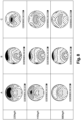
- FIG 8 presents a series of comparative cross-sectional views of the behavior of the air flow I at the end of zone IV, for an air intake pipe devoid of any straightening system (column A), for a pipe air intake provided with a system of the prior art (column B) and for an air intake assembly 100 according to the invention (column C).
- the cuts are made in a transverse plane of the elbow 104, and are given for three different throughput values: 220 kg/h, 440 kg/h and 880 kg/h.
- the air intake assembly 100 has the lowest average flow velocities for the region between 0.4D and 4D, this region corresponding to the positioning zone of the flowmeter 102.
- the air intake assembly 100 makes it possible to slow down and standardize the speed of the air flow to allow better reliability of reading of the flow rate by the flow meter.
Landscapes
- Engineering & Computer Science (AREA)
- Chemical & Material Sciences (AREA)
- Physics & Mathematics (AREA)
- Fluid Mechanics (AREA)
- Combustion & Propulsion (AREA)
- Mechanical Engineering (AREA)
- General Engineering & Computer Science (AREA)
- Measuring Volume Flow (AREA)
- General Physics & Mathematics (AREA)
- Analytical Chemistry (AREA)
- Characterised By The Charging Evacuation (AREA)
Description
- La présente invention concerne un ensemble d'admission d'air pour un moteur automobile, qui comprend un dispositif de redressement d'un flux d'air d'un tuyau d'admission d'air d'un véhicule automobile, pour optimiser la lecture d'un débitmètre.
- Les moteurs à combustion interne fonctionnent sur le principe de la combustion d'air et de carburant. Dans le cas des véhicules automobiles, l'air utilisé provient d'une ligne d'admission d'air qui permet de capter de l'air à l'extérieur du véhicule et de le filtrer avant qu'il ne soit injecté dans le moteur.
- D'une manière courante, les véhicules automobiles comprennent un débitmètre positionné dans un tuyau de la ligne d'admission d'air. Le débitmètre est un instrument de mesure permettant de détecter le débit d'air entrant dans le moteur. Cette détection permet notamment de contrôler le rapport stoechiométrique entre l'air et le combustible dans le moteur. De plus, le débitmètre permet aussi de contrôler le taux de recyclage des gaz d'échappement qui sont réinjectés dans le moteur. Par extension, les mesures du débitmètre sont utilisées pour les homologations aux normes de pollution des véhicules.
- Le débitmètre est donc un élément essentiel dont les mesures doivent être les plus précises possible. Or, le plus souvent, le débitmètre est positionné dans le tuyau d'admission d'air à la sortie de la boite à filtre, dans une zone dans laquelle le flux d'air est instable. En outre, en raison des contraintes de place dans le compartiment moteur du véhicule, le débitmètre est souvent positionné à la sortie d'un coude, ce qui augmente l'instabilité du flux d'air. L'instabilité du flux d'air fausse certaines mesures du débitmètre. Pour stabiliser le flux d'air il est connu de positionner une grille standard en amont du débitmètre. Cette disposition permet de redresser (stabiliser) une partie du flux d'air, mais s'avère insuffisante sur l'ensemble de la plage de débits d'air du fonctionnement du moteur. Ainsi, cette disposition se révèle, par exemple, insatisfaisante pour les bas débits d'air.
- Des solutions permettant de mesurer de manière plus précise le débit d'air par un débitmètre dans une ligne d'admission d'air ont été par ailleurs décrites dans les documents
GB 2 402 971 US 5 918 279 etDE 41 17 110 . - Dans ce contexte, la présente invention a pour objectif de fournir un ensemble d'admission d'air pour un moteur automobile qui permette de stabiliser le flux d'air sur l'ensemble de la plage de débits d'air du fonctionnement du moteur, pour permettre une mesure plus précise du débit d'air par un débitmètre.
- L'invention concerne un ensemble d'admission d'air selon la revendication indépendante 1.
- D'une manière particulièrement avantageuse, les différences de dimensions entre les cellules permettent de stabiliser le flux d'air sur l'ensemble de la plage de débits d'air du fonctionnement du moteur, pour permettre une mesure précise du débit d'air par un débitmètre. Ainsi, l'invention propose un ensemble d'admission d'air pour un moteur automobile qui permet de stabiliser le flux d'air sur l'ensemble de la plage de débits d'air du fonctionnement du moteur, pour permettre une mesure précise du débit d'air par un débitmètre.
- Les parois annulaires peuvent être reliées par un réseau d'entretoises.
- Selon une disposition particulière, la partie périphérique peut présenter une section transversale sensiblement circulaire.
- Le tuyau d'admission d'air peut présenter un coude en aval duquel est positionné le dispositif de redressement d'un flux d'air.
- Les cellules de plus faibles dimensions du dispositif de redressement d'un flux d'air peuvent être positionnées vers l'intérieur du coude.
- D'autres caractéristiques et avantages de la présente invention ressortiront clairement de la description détaillée ci-après de deux modes de réalisation de l'invention donnés à titre d'exemples non limitatifs, en référence aux dessins annexés dans lesquels :
- La
figure 1 est une représentation schématique en perspective d'un ensemble d'admission d'air selon un premier mode de réalisation qui n'est pas conforme à l'invention revendiquée ; - La
figure 2 est une représentation schématique de face d'un dispositif de redressement selon le premier mode de réalisation; - La
figure 3 est une vue de face d'un dispositif de redressement selon le premier mode de réalisation; - La
figure 4 est une représentation schématique en perspective d'un ensemble d'admission d'air selon un deuxième mode de réalisation de l'invention ; - La
figure 5 est une représentation schématique de face d'un dispositif de redressement selon le deuxième mode de réalisation de l'invention ; - La
figure 6 est une représentation schématique de côté d'un dispositif de redressement selon l'invention ; - La
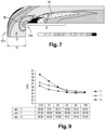
figure 7 est une représentation du comportement d'un flux d'air dans un coude dépourvu de dispositif de redressement ; - La
figure 8 est tableau comparatif du comportement d'un flux d'air dans un coude dépourvu de dispositif de redressement, dans un coude comprenant un dispositif de redressement de l'art antérieur et dans un ensemble d'admission d'air selon l'invention ; - La
figure 9 est un graphique comparatif de l'évolution de la vitesse d'écoulement d'un flux d'air dans un coude, en fonction de la distance par rapport au coude, pour un coude dépourvu de dispositif de redressement, dans un coude comprenant un dispositif de redressement de l'art antérieur et dans un ensemble d'admission d'air selon l'invention. - L'invention porte sur un ensemble d'admission d'air 100, pour un véhicule automobile.
- L'ensemble d'admission d'air 100 comprend un tuyau d'admission d'air 101 présentant un coude 104 en aval duquel sont positionnés un dispositif de redressement d'un flux d'air 1 et un débitmètre 102.
- Le dispositif de redressement d'un flux d'air 1 comprend une partie périphérique 3 et une partie ajourée 4 fixée à la partie périphérique 3.
- Le dispositif de redressement d'un flux d'air 1 peut, par exemple, être réalisé en tôle, ou peut être réalisé en matériau plastique moulé ou injecté.
- Selon les exemples ici présentés, la partie périphérique 3 présente une section transversale sensiblement circulaire. La partie périphérique 3 peut être dimensionnée pour être ajustée serrée dans un tuyau d'admission d'air 101. Selon les exemples présentés en
figure 1 ,4 et6 , la partie périphérique 3 présente une première face transversale 8 et une deuxième face transversale 9. Entre la première face transversale 8 et la deuxième face transversale 9, la partie périphérique 3 présente une cote longitudinale 7 variable suivant un axe longitudinal II de la partie périphérique. Selon l'exemple présenté enfigure 4 , la deuxième face transversale 9 présente une portion concave 9a et une portion convexe 9b. Cette géométrie particulière de la deuxième face transversale 9 fait varier la cote longitudinale 7 entre un minimum et un maximum. La cote longitudinale 7 variable est une disposition technique de l'invention particulièrement avantageuse dont la fonction sera détaillée ultérieurement. - La partie ajourée 4 est fixée à la partie périphérique 3. Selon les exemples ici présentés, la partie ajourée 4 peut être venue de moulage avec la partie périphérique 3.
- La partie ajourée 4 comprend une pluralité de parois 11 définissant des cellules 15.
- Selon un premier mode de réalisation présenté en
figure 2 , la partie ajourée 4 comprend une première série de parois 11a planes orientées suivant l'axe longitudinal II de la partie périphérique 3, parallèles entre elles, et une deuxième série de parois 11b planes orientées suivant l'axe longitudinal II de la partie périphérique 3, parallèles entre elles et sécantes au parois 11a planes de la première série pour former une grille 12. - Chaque paroi 11a et 11b plane présente une cote longitudinale égale à la cote longitudinale 7 de la partie périphérique 3.
- La grille 12 définit une pluralité de cellules 15 traversantes. Les parois 11a et 11b planes sont écartées selon un pas 17 variable et irrégulier, de telle sorte que les cellules 15 présentent des dimensions différentes. La fonction des cellules 15 présentant des dimensions différentes sera détaillée ultérieurement.
- Selon un deuxième mode de réalisation présenté en
figure 3 , la partie ajourée 4 comprend une pluralité de parois 11c annulaires. Chaque paroi 11c annulaire présente une cote longitudinale égale à la cote longitudinale 7 de la partie périphérique 3. Les parois 11c annulaires sont maintenues par un réseau d'entretoises (non représenté). - Les parois 11c annulaires délimitent des cellules 15 traversantes. Les parois 11c annulaires sont excentriques les unes par rapport aux autres, et sont aussi excentriques par rapport à la partie périphérique 3. Ainsi les cellules 15 entre les parois 11c annulaires présentent des dimensions distinctes.
- Le dispositif de redressement d'un flux d'air 1 est positionné en amont du débitmètre 102 par rapport au sens I de circulation du flux d'air dans le tuyau d'admission d'air 101. Le dispositif de redressement du flux d'air 1 peut être positionné de sorte que les cellules 15 de plus faibles dimensions soient orientées vers l'intérieur du coude 104.
- En condition d'utilisation, tel que représenté sur la
figure 7 , dans un tuyau d'admission d'air 101 démuni de dispositif de redressement d'un flux d'air 1, on observe que le flux d'air I présente une vitesse plus importante dans la zone III à l'intérieur du coude 104, que dans le reste du coude 104. Cette différence de vitesse dans le coude 104, engendre une dépression à la sortie du coude 104, qui se traduit par une forte perte de vitesse du flux dans la zone IV à l'issue du coude 104. Il en résulte des turbulences et un important décalage de vitesses au sein du flux d'air I, dans la zone V dans laquelle le débitmètre 102 est usuellement positionné. - Comme représenté sur les
figures 1 et4 , le dispositif de redressement d'un flux d'air 1 est positionné dans la zone IV. Ainsi, à la sortie du coude 104, le flux I traverse le dispositif de redressement d'un flux d'air 1. En traversant le dispositif de redressement d'un flux d'air 1, le flux d'air I s'écoule dans les différentes cellules 15. Les différences de volumes entre les cellules 15 permettent de stabiliser le flux d'air I sur toute la plage de débits d'air du fonctionnement du moteur, pour permettre une mesure plus précise du débit d'air par le débitmètre 102. Par stabiliser, on entend que le dispositif de redressement d'un flux d'air 1 permet d'homogénéiser les vitesses d'écoulement du flux d'air I. - Pour apprécier quantitativement les améliorations apportées par l'invention, on peut se reporter à la
figure 8 qui présente une série de vues en coupe comparatives du comportement du flux d'air I à l'issue de la zone IV, pour un tuyau d'admission d'air dépourvu de tout système de redressement (colonne A), pour un tuyau d'admission d'air muni d'un système de l'art antérieur (colonne B) et pour un ensemble d'admission d'air 100 selon l'invention (colonne C). Les coupes sont réalisées dans un plan transversal du coude 104, et sont données pour trois valeurs de débit différentes : 220 kg/h, 440 kg/h et 880 kg/h. Ainsi, il apparaît que pour les trois vitesses testées, le dispositif de redressement d'un flux d'air 1 permet d'obtenir un flux d'air I présentant une meilleure homogénéité de vitesses d'écoulement. - On peut aussi se reporter au graphique de la
figure 9 qui représente la vitesse moyenne d'écoulement en fonction de la distance au coude 104. La distance est calculée en multiple du diamètre D du coude 104. Le graphique permet de comparer la vitesse moyenne d'écoulement pour un coude dépourvu de tout système de redressement (courbe E), pour un coude muni d'un système de l'art antérieur (courbe F) et pour un ensemble d'admission d'air 100 selon l'invention (courbe G). - Comme on peut l'observer, l'ensemble d'admission d'air 100 présente les vitesses moyennes d'écoulement les plus faibles pour la région comprise entre 0.4D et 4D, cette région correspondant à la zone de positionnement du débitmètre 102.
- Ainsi, l'ensemble d'admission d'air 100 permet de ralentir et homogénéiser la vitesse du flux d'air pour permettre une meilleure fiabilité de lecture du débit par le débitmètre.
Claims (5)
- Ensemble d'admission d'air (100) pour un moteur automobile, comprenant un tuyau d'admission d'air (101), un débitmètre (102) et un dispositif de redressement d'un flux d'air (1) positionné en amont du débitmètre (102) par rapport au sens (I) de circulation du flux d'air dans le tuyau (101), le dispositif de redressement d'un flux d'air (1) comprenant une partie périphérique (3) et une partie ajourée (4) fixée à la partie périphérique (3), ladite partie ajourée (4) comprenant une pluralité de parois (11c) annulaires, la partie périphérique (3) comprenant une première face transversale (8) et une deuxième face transversale (9) et la partie ajourée (4) comprenant une pluralité de parois (11) définissant une pluralité de cellules (15) traversantes, lesdites cellules (15) entre les parois (11c) annulaires présentant des dimensions distinctes, l'ensemble d'admission d'air (100) étant caractérisé en ce que, entre la première face transversale (8) et la deuxième face transversale (9), la partie périphérique (3) présente une cote longitudinale (7) variable suivant un axe longitudinal (II) de la partie périphérique, la deuxième face transversale (9) présentant une portion concave (9a) et une portion convexe (9b) faisant varier la côte longitudinale (7) entre un maximum et un minimum et en ce que les parois (11c) annulaires sont excentriques les unes par rapport aux autres et sont aussi excentriques par rapport à la partie périphérique (3).
- Ensemble d'admission d'air (100) selon la revendication 1, caractérisé en ce que les parois (11c) annulaires sont reliées par un réseau d'entretoises.
- Ensemble d'admission d'air (100) selon la revendication 1 ou 2, caractérisé en ce que la partie périphérique (3) présente une section transversale sensiblement circulaire.
- Ensemble d'admission d'air (100) selon l'une quelconque des revendications 1 à 3, caractérisé en ce que le tuyau d'admission d'air (101) présente un coude (104) en aval duquel est positionné le dispositif de redressement d'un flux d'air (1).
- Ensemble d'admission d'air (100) selon la revendication 4, caractérisé en ce que les cellules (15) de plusfaibles dimensions du dispositif de redressement d'un flux d'air (1) sont positionnées vers l'intérieur du coude (104).
Applications Claiming Priority (2)
| Application Number | Priority Date | Filing Date | Title |
|---|---|---|---|
| FR1759409A FR3072131B1 (fr) | 2017-10-06 | 2017-10-06 | Ensemble d'admission d'air |
| PCT/FR2018/052386 WO2019068992A1 (fr) | 2017-10-06 | 2018-09-28 | Ensemble d'admission d'air |
Publications (2)
| Publication Number | Publication Date |
|---|---|
| EP3669066A1 EP3669066A1 (fr) | 2020-06-24 |
| EP3669066B1 true EP3669066B1 (fr) | 2023-06-07 |
Family
ID=60382418
Family Applications (1)
| Application Number | Title | Priority Date | Filing Date |
|---|---|---|---|
| EP18808410.7A Active EP3669066B1 (fr) | 2017-10-06 | 2018-09-28 | Ensemble d'admission d'air |
Country Status (4)
| Country | Link |
|---|---|
| EP (1) | EP3669066B1 (fr) |
| ES (1) | ES2952986T3 (fr) |
| FR (1) | FR3072131B1 (fr) |
| WO (1) | WO2019068992A1 (fr) |
Families Citing this family (1)
| Publication number | Priority date | Publication date | Assignee | Title |
|---|---|---|---|---|
| CN118111523B (zh) * | 2024-04-26 | 2024-08-16 | 潍柴动力股份有限公司 | 一种整流格栅、空气流量传感器及整流格栅的设计方法 |
Family Cites Families (3)
| Publication number | Priority date | Publication date | Assignee | Title |
|---|---|---|---|---|
| DE19647081A1 (de) * | 1996-11-14 | 1998-05-28 | Bosch Gmbh Robert | Vorrichtung zur Messung der Masse eines strömenden Mediums |
| US6920784B2 (en) * | 2003-06-18 | 2005-07-26 | Visteon Global Technologies, Inc. | Flow conditioning device |
| DE102012211126A1 (de) * | 2012-06-28 | 2014-01-02 | Robert Bosch Gmbh | Sensoranordnung zur Bestimmung wenigstens einer Strömungseigenschaft eines mit einer Hauptströmungsrichtung strömenden fluiden Mediums |
-
2017
- 2017-10-06 FR FR1759409A patent/FR3072131B1/fr not_active Expired - Fee Related
-
2018
- 2018-09-28 ES ES18808410T patent/ES2952986T3/es active Active
- 2018-09-28 EP EP18808410.7A patent/EP3669066B1/fr active Active
- 2018-09-28 WO PCT/FR2018/052386 patent/WO2019068992A1/fr not_active Ceased
Also Published As
| Publication number | Publication date |
|---|---|
| FR3072131B1 (fr) | 2021-03-05 |
| WO2019068992A1 (fr) | 2019-04-11 |
| ES2952986T3 (es) | 2023-11-07 |
| EP3669066A1 (fr) | 2020-06-24 |
| FR3072131A1 (fr) | 2019-04-12 |
Similar Documents
| Publication | Publication Date | Title |
|---|---|---|
| EP3408514B1 (fr) | Echangeur thermique surfacique et traitement acoustique | |
| US20070169548A1 (en) | Air flow measuring device | |
| EP0434578A1 (fr) | Sortie d'échappement à venturi | |
| EP3669066B1 (fr) | Ensemble d'admission d'air | |
| EP3365547B1 (fr) | Dispositif d'atténuation acoustique pour une ligne d'admission | |
| EP3274578B1 (fr) | Dispositif a grilles d'ejection de microjets pour la reduction du bruit de jet d'une turbomachine | |
| EP3626954B1 (fr) | Procede de determination d'un indicateur de cliquetis par determination de la pression globale dans le cylindre | |
| FR3072130B1 (fr) | Ensemble d'admission d'air | |
| KR100909704B1 (ko) | 자동차 배출가스유량 측정장치 | |
| Renz et al. | Improving a Centrifugal Compressor's Performance at Low Mass Flow Rates by Adding an Acoustic Resonator | |
| Park et al. | Study on analytic of opening angles for Muffler variable valve of automobile | |
| EP2497928A1 (fr) | Procédé de détection d'un défaut dans un système comportant un moteur a combustion interne et un turbocompresseur | |
| JP2021038701A (ja) | 排気通路 | |
| JP6312192B2 (ja) | 排気ガス再循環装置用ピトー管式エアフローメータ | |
| WO2009098384A1 (fr) | Procédé de mesure de débit massique de gaz d'échappement circulant dans un système egr d'un moteur thermique de véhicule automobile et débitmètre correspondant. | |
| FR3072132B1 (fr) | Ensemble d'admission d'air | |
| FR3101944A1 (fr) | Portion de conduit d’admission comportant un débitmètre et son écran de protection | |
| WO2024079278A1 (fr) | Sonde de captage de pression | |
| EP2066892B1 (fr) | Systeme de commande d'un moteur à combustion interne de véhicule automobile comprenant un circuit de recirculation des gaz d'échappement du moteur muni d'une vanne de recirculation commandée | |
| CN120291957A (zh) | 排气压力的确定方法、装置及车辆 | |
| FR2905141A1 (fr) | Systeme d'admission de gaz dans un moteur a combustion interne, notamment du type diesel | |
| JP3610444B2 (ja) | エンジン排ガス流量計測システム | |
| JP3610444B6 (ja) | エンジン排ガス流量計測システム | |
| FR3075872A3 (fr) | Methode et dispositif de determination du fonctionnement d'un filtre a particules | |
| WO2011144833A1 (fr) | Moteur thermique equipe d'un turbocompresseur de suralimentation |
Legal Events
| Date | Code | Title | Description |
|---|---|---|---|
| STAA | Information on the status of an ep patent application or granted ep patent |
Free format text: STATUS: UNKNOWN |
|
| STAA | Information on the status of an ep patent application or granted ep patent |
Free format text: STATUS: THE INTERNATIONAL PUBLICATION HAS BEEN MADE |
|
| PUAI | Public reference made under article 153(3) epc to a published international application that has entered the european phase |
Free format text: ORIGINAL CODE: 0009012 |
|
| STAA | Information on the status of an ep patent application or granted ep patent |
Free format text: STATUS: REQUEST FOR EXAMINATION WAS MADE |
|
| 17P | Request for examination filed |
Effective date: 20200318 |
|
| AK | Designated contracting states |
Kind code of ref document: A1 Designated state(s): AL AT BE BG CH CY CZ DE DK EE ES FI FR GB GR HR HU IE IS IT LI LT LU LV MC MK MT NL NO PL PT RO RS SE SI SK SM TR |
|
| AX | Request for extension of the european patent |
Extension state: BA ME |
|
| DAV | Request for validation of the european patent (deleted) | ||
| DAX | Request for extension of the european patent (deleted) | ||
| STAA | Information on the status of an ep patent application or granted ep patent |
Free format text: STATUS: EXAMINATION IS IN PROGRESS |
|
| 17Q | First examination report despatched |
Effective date: 20210420 |
|
| GRAP | Despatch of communication of intention to grant a patent |
Free format text: ORIGINAL CODE: EPIDOSNIGR1 |
|
| STAA | Information on the status of an ep patent application or granted ep patent |
Free format text: STATUS: GRANT OF PATENT IS INTENDED |
|
| INTG | Intention to grant announced |
Effective date: 20230118 |
|
| GRAS | Grant fee paid |
Free format text: ORIGINAL CODE: EPIDOSNIGR3 |
|
| GRAA | (expected) grant |
Free format text: ORIGINAL CODE: 0009210 |
|
| STAA | Information on the status of an ep patent application or granted ep patent |
Free format text: STATUS: THE PATENT HAS BEEN GRANTED |
|
| AK | Designated contracting states |
Kind code of ref document: B1 Designated state(s): AL AT BE BG CH CY CZ DE DK EE ES FI FR GB GR HR HU IE IS IT LI LT LU LV MC MK MT NL NO PL PT RO RS SE SI SK SM TR |
|
| REG | Reference to a national code |
Ref country code: GB Ref legal event code: FG4D Free format text: NOT ENGLISH |
|
| REG | Reference to a national code |
Ref country code: CH Ref legal event code: EP Ref country code: AT Ref legal event code: REF Ref document number: 1575762 Country of ref document: AT Kind code of ref document: T Effective date: 20230615 Ref country code: DE Ref legal event code: R096 Ref document number: 602018051346 Country of ref document: DE |
|
| REG | Reference to a national code |
Ref country code: LT Ref legal event code: MG9D |
|
| REG | Reference to a national code |
Ref country code: NL Ref legal event code: MP Effective date: 20230607 |
|
| PG25 | Lapsed in a contracting state [announced via postgrant information from national office to epo] |
Ref country code: SE Free format text: LAPSE BECAUSE OF FAILURE TO SUBMIT A TRANSLATION OF THE DESCRIPTION OR TO PAY THE FEE WITHIN THE PRESCRIBED TIME-LIMIT Effective date: 20230607 Ref country code: NO Free format text: LAPSE BECAUSE OF FAILURE TO SUBMIT A TRANSLATION OF THE DESCRIPTION OR TO PAY THE FEE WITHIN THE PRESCRIBED TIME-LIMIT Effective date: 20230907 |
|
| RAP4 | Party data changed (patent owner data changed or rights of a patent transferred) |
Owner name: NOVARES FRANCE |
|
| REG | Reference to a national code |
Ref country code: AT Ref legal event code: MK05 Ref document number: 1575762 Country of ref document: AT Kind code of ref document: T Effective date: 20230607 |
|
| PG25 | Lapsed in a contracting state [announced via postgrant information from national office to epo] |
Ref country code: RS Free format text: LAPSE BECAUSE OF FAILURE TO SUBMIT A TRANSLATION OF THE DESCRIPTION OR TO PAY THE FEE WITHIN THE PRESCRIBED TIME-LIMIT Effective date: 20230607 Ref country code: NL Free format text: LAPSE BECAUSE OF FAILURE TO SUBMIT A TRANSLATION OF THE DESCRIPTION OR TO PAY THE FEE WITHIN THE PRESCRIBED TIME-LIMIT Effective date: 20230607 Ref country code: LV Free format text: LAPSE BECAUSE OF FAILURE TO SUBMIT A TRANSLATION OF THE DESCRIPTION OR TO PAY THE FEE WITHIN THE PRESCRIBED TIME-LIMIT Effective date: 20230607 Ref country code: LT Free format text: LAPSE BECAUSE OF FAILURE TO SUBMIT A TRANSLATION OF THE DESCRIPTION OR TO PAY THE FEE WITHIN THE PRESCRIBED TIME-LIMIT Effective date: 20230607 Ref country code: HR Free format text: LAPSE BECAUSE OF FAILURE TO SUBMIT A TRANSLATION OF THE DESCRIPTION OR TO PAY THE FEE WITHIN THE PRESCRIBED TIME-LIMIT Effective date: 20230607 Ref country code: GR Free format text: LAPSE BECAUSE OF FAILURE TO SUBMIT A TRANSLATION OF THE DESCRIPTION OR TO PAY THE FEE WITHIN THE PRESCRIBED TIME-LIMIT Effective date: 20230908 |
|
| PGFP | Annual fee paid to national office [announced via postgrant information from national office to epo] |
Ref country code: DE Payment date: 20230915 Year of fee payment: 6 |
|
| PG25 | Lapsed in a contracting state [announced via postgrant information from national office to epo] |
Ref country code: FI Free format text: LAPSE BECAUSE OF FAILURE TO SUBMIT A TRANSLATION OF THE DESCRIPTION OR TO PAY THE FEE WITHIN THE PRESCRIBED TIME-LIMIT Effective date: 20230607 |
|
| PG25 | Lapsed in a contracting state [announced via postgrant information from national office to epo] |
Ref country code: SK Free format text: LAPSE BECAUSE OF FAILURE TO SUBMIT A TRANSLATION OF THE DESCRIPTION OR TO PAY THE FEE WITHIN THE PRESCRIBED TIME-LIMIT Effective date: 20230607 |
|
| PGFP | Annual fee paid to national office [announced via postgrant information from national office to epo] |
Ref country code: ES Payment date: 20231009 Year of fee payment: 6 |
|
| PG25 | Lapsed in a contracting state [announced via postgrant information from national office to epo] |
Ref country code: IS Free format text: LAPSE BECAUSE OF FAILURE TO SUBMIT A TRANSLATION OF THE DESCRIPTION OR TO PAY THE FEE WITHIN THE PRESCRIBED TIME-LIMIT Effective date: 20231007 |
|
| PG25 | Lapsed in a contracting state [announced via postgrant information from national office to epo] |
Ref country code: SM Free format text: LAPSE BECAUSE OF FAILURE TO SUBMIT A TRANSLATION OF THE DESCRIPTION OR TO PAY THE FEE WITHIN THE PRESCRIBED TIME-LIMIT Effective date: 20230607 Ref country code: SK Free format text: LAPSE BECAUSE OF FAILURE TO SUBMIT A TRANSLATION OF THE DESCRIPTION OR TO PAY THE FEE WITHIN THE PRESCRIBED TIME-LIMIT Effective date: 20230607 Ref country code: RO Free format text: LAPSE BECAUSE OF FAILURE TO SUBMIT A TRANSLATION OF THE DESCRIPTION OR TO PAY THE FEE WITHIN THE PRESCRIBED TIME-LIMIT Effective date: 20230607 Ref country code: PT Free format text: LAPSE BECAUSE OF FAILURE TO SUBMIT A TRANSLATION OF THE DESCRIPTION OR TO PAY THE FEE WITHIN THE PRESCRIBED TIME-LIMIT Effective date: 20231009 Ref country code: IS Free format text: LAPSE BECAUSE OF FAILURE TO SUBMIT A TRANSLATION OF THE DESCRIPTION OR TO PAY THE FEE WITHIN THE PRESCRIBED TIME-LIMIT Effective date: 20231007 Ref country code: EE Free format text: LAPSE BECAUSE OF FAILURE TO SUBMIT A TRANSLATION OF THE DESCRIPTION OR TO PAY THE FEE WITHIN THE PRESCRIBED TIME-LIMIT Effective date: 20230607 Ref country code: CZ Free format text: LAPSE BECAUSE OF FAILURE TO SUBMIT A TRANSLATION OF THE DESCRIPTION OR TO PAY THE FEE WITHIN THE PRESCRIBED TIME-LIMIT Effective date: 20230607 Ref country code: AT Free format text: LAPSE BECAUSE OF FAILURE TO SUBMIT A TRANSLATION OF THE DESCRIPTION OR TO PAY THE FEE WITHIN THE PRESCRIBED TIME-LIMIT Effective date: 20230607 |
|
| PG25 | Lapsed in a contracting state [announced via postgrant information from national office to epo] |
Ref country code: PL Free format text: LAPSE BECAUSE OF FAILURE TO SUBMIT A TRANSLATION OF THE DESCRIPTION OR TO PAY THE FEE WITHIN THE PRESCRIBED TIME-LIMIT Effective date: 20230607 |
|
| REG | Reference to a national code |
Ref country code: DE Ref legal event code: R097 Ref document number: 602018051346 Country of ref document: DE |
|
| PLBE | No opposition filed within time limit |
Free format text: ORIGINAL CODE: 0009261 |
|
| STAA | Information on the status of an ep patent application or granted ep patent |
Free format text: STATUS: NO OPPOSITION FILED WITHIN TIME LIMIT |
|
| PG25 | Lapsed in a contracting state [announced via postgrant information from national office to epo] |
Ref country code: DK Free format text: LAPSE BECAUSE OF FAILURE TO SUBMIT A TRANSLATION OF THE DESCRIPTION OR TO PAY THE FEE WITHIN THE PRESCRIBED TIME-LIMIT Effective date: 20230607 |
|
| REG | Reference to a national code |
Ref country code: CH Ref legal event code: PL |
|
| PG25 | Lapsed in a contracting state [announced via postgrant information from national office to epo] |
Ref country code: SI Free format text: LAPSE BECAUSE OF FAILURE TO SUBMIT A TRANSLATION OF THE DESCRIPTION OR TO PAY THE FEE WITHIN THE PRESCRIBED TIME-LIMIT Effective date: 20230607 |
|
| 26N | No opposition filed |
Effective date: 20240308 |
|
| PG25 | Lapsed in a contracting state [announced via postgrant information from national office to epo] |
Ref country code: LU Free format text: LAPSE BECAUSE OF NON-PAYMENT OF DUE FEES Effective date: 20230928 |
|
| REG | Reference to a national code |
Ref country code: BE Ref legal event code: MM Effective date: 20230930 |
|
| GBPC | Gb: european patent ceased through non-payment of renewal fee |
Effective date: 20230928 |
|
| PG25 | Lapsed in a contracting state [announced via postgrant information from national office to epo] |
Ref country code: SI Free format text: LAPSE BECAUSE OF FAILURE TO SUBMIT A TRANSLATION OF THE DESCRIPTION OR TO PAY THE FEE WITHIN THE PRESCRIBED TIME-LIMIT Effective date: 20230607 Ref country code: LU Free format text: LAPSE BECAUSE OF NON-PAYMENT OF DUE FEES Effective date: 20230928 Ref country code: IT Free format text: LAPSE BECAUSE OF FAILURE TO SUBMIT A TRANSLATION OF THE DESCRIPTION OR TO PAY THE FEE WITHIN THE PRESCRIBED TIME-LIMIT Effective date: 20230607 Ref country code: MC Free format text: LAPSE BECAUSE OF FAILURE TO SUBMIT A TRANSLATION OF THE DESCRIPTION OR TO PAY THE FEE WITHIN THE PRESCRIBED TIME-LIMIT Effective date: 20230607 |
|
| REG | Reference to a national code |
Ref country code: IE Ref legal event code: MM4A |
|
| PG25 | Lapsed in a contracting state [announced via postgrant information from national office to epo] |
Ref country code: IE Free format text: LAPSE BECAUSE OF NON-PAYMENT OF DUE FEES Effective date: 20230928 |
|
| PG25 | Lapsed in a contracting state [announced via postgrant information from national office to epo] |
Ref country code: GB Free format text: LAPSE BECAUSE OF NON-PAYMENT OF DUE FEES Effective date: 20230928 |
|
| PG25 | Lapsed in a contracting state [announced via postgrant information from national office to epo] |
Ref country code: CH Free format text: LAPSE BECAUSE OF NON-PAYMENT OF DUE FEES Effective date: 20230930 |
|
| PG25 | Lapsed in a contracting state [announced via postgrant information from national office to epo] |
Ref country code: IE Free format text: LAPSE BECAUSE OF NON-PAYMENT OF DUE FEES Effective date: 20230928 Ref country code: GB Free format text: LAPSE BECAUSE OF NON-PAYMENT OF DUE FEES Effective date: 20230928 Ref country code: CH Free format text: LAPSE BECAUSE OF NON-PAYMENT OF DUE FEES Effective date: 20230930 |
|
| PG25 | Lapsed in a contracting state [announced via postgrant information from national office to epo] |
Ref country code: BE Free format text: LAPSE BECAUSE OF NON-PAYMENT OF DUE FEES Effective date: 20230930 |
|
| PG25 | Lapsed in a contracting state [announced via postgrant information from national office to epo] |
Ref country code: BG Free format text: LAPSE BECAUSE OF FAILURE TO SUBMIT A TRANSLATION OF THE DESCRIPTION OR TO PAY THE FEE WITHIN THE PRESCRIBED TIME-LIMIT Effective date: 20230607 |
|
| PG25 | Lapsed in a contracting state [announced via postgrant information from national office to epo] |
Ref country code: BG Free format text: LAPSE BECAUSE OF FAILURE TO SUBMIT A TRANSLATION OF THE DESCRIPTION OR TO PAY THE FEE WITHIN THE PRESCRIBED TIME-LIMIT Effective date: 20230607 |
|
| REG | Reference to a national code |
Ref country code: DE Ref legal event code: R119 Ref document number: 602018051346 Country of ref document: DE |
|
| PG25 | Lapsed in a contracting state [announced via postgrant information from national office to epo] |
Ref country code: DE Free format text: LAPSE BECAUSE OF NON-PAYMENT OF DUE FEES Effective date: 20250401 |
|
| PG25 | Lapsed in a contracting state [announced via postgrant information from national office to epo] |
Ref country code: CY Free format text: LAPSE BECAUSE OF FAILURE TO SUBMIT A TRANSLATION OF THE DESCRIPTION OR TO PAY THE FEE WITHIN THE PRESCRIBED TIME-LIMIT; INVALID AB INITIO Effective date: 20180928 |
|
| PG25 | Lapsed in a contracting state [announced via postgrant information from national office to epo] |
Ref country code: HU Free format text: LAPSE BECAUSE OF FAILURE TO SUBMIT A TRANSLATION OF THE DESCRIPTION OR TO PAY THE FEE WITHIN THE PRESCRIBED TIME-LIMIT; INVALID AB INITIO Effective date: 20180928 |
|
| PGFP | Annual fee paid to national office [announced via postgrant information from national office to epo] |
Ref country code: FR Payment date: 20250731 Year of fee payment: 8 |
|
| REG | Reference to a national code |
Ref country code: ES Ref legal event code: FD2A Effective date: 20251031 |
|
| PG25 | Lapsed in a contracting state [announced via postgrant information from national office to epo] |
Ref country code: TR Free format text: LAPSE BECAUSE OF FAILURE TO SUBMIT A TRANSLATION OF THE DESCRIPTION OR TO PAY THE FEE WITHIN THE PRESCRIBED TIME-LIMIT Effective date: 20230607 |
|
| PG25 | Lapsed in a contracting state [announced via postgrant information from national office to epo] |
Ref country code: ES Free format text: LAPSE BECAUSE OF NON-PAYMENT OF DUE FEES Effective date: 20240929 |