EP3669065B1 - Lufteinlassanordnung - Google Patents
Lufteinlassanordnung Download PDFInfo
- Publication number
- EP3669065B1 EP3669065B1 EP18793246.2A EP18793246A EP3669065B1 EP 3669065 B1 EP3669065 B1 EP 3669065B1 EP 18793246 A EP18793246 A EP 18793246A EP 3669065 B1 EP3669065 B1 EP 3669065B1
- Authority
- EP
- European Patent Office
- Prior art keywords
- flow
- air
- air flow
- air intake
- intake assembly
- Prior art date
- Legal status (The legal status is an assumption and is not a legal conclusion. Google has not performed a legal analysis and makes no representation as to the accuracy of the status listed.)
- Active
Links
Images
Classifications
-
- F—MECHANICAL ENGINEERING; LIGHTING; HEATING; WEAPONS; BLASTING
- F02—COMBUSTION ENGINES; HOT-GAS OR COMBUSTION-PRODUCT ENGINE PLANTS
- F02M—SUPPLYING COMBUSTION ENGINES IN GENERAL WITH COMBUSTIBLE MIXTURES OR CONSTITUENTS THEREOF
- F02M35/00—Combustion-air cleaners, air intakes, intake silencers, or induction systems specially adapted for, or arranged on, internal-combustion engines
- F02M35/10—Air intakes; Induction systems
- F02M35/10242—Devices or means connected to or integrated into air intakes; Air intakes combined with other engine or vehicle parts
- F02M35/10262—Flow guides, obstructions, deflectors or the like
-
- F—MECHANICAL ENGINEERING; LIGHTING; HEATING; WEAPONS; BLASTING
- F02—COMBUSTION ENGINES; HOT-GAS OR COMBUSTION-PRODUCT ENGINE PLANTS
- F02M—SUPPLYING COMBUSTION ENGINES IN GENERAL WITH COMBUSTIBLE MIXTURES OR CONSTITUENTS THEREOF
- F02M35/00—Combustion-air cleaners, air intakes, intake silencers, or induction systems specially adapted for, or arranged on, internal-combustion engines
- F02M35/10—Air intakes; Induction systems
- F02M35/10091—Air intakes; Induction systems characterised by details of intake ducts: shapes; connections; arrangements
-
- F—MECHANICAL ENGINEERING; LIGHTING; HEATING; WEAPONS; BLASTING
- F02—COMBUSTION ENGINES; HOT-GAS OR COMBUSTION-PRODUCT ENGINE PLANTS
- F02M—SUPPLYING COMBUSTION ENGINES IN GENERAL WITH COMBUSTIBLE MIXTURES OR CONSTITUENTS THEREOF
- F02M35/00—Combustion-air cleaners, air intakes, intake silencers, or induction systems specially adapted for, or arranged on, internal-combustion engines
- F02M35/10—Air intakes; Induction systems
- F02M35/10373—Sensors for intake systems
- F02M35/10386—Sensors for intake systems for flow rate
-
- G—PHYSICS
- G01—MEASURING; TESTING
- G01F—MEASURING VOLUME, VOLUME FLOW, MASS FLOW OR LIQUID LEVEL; METERING BY VOLUME
- G01F1/00—Measuring the volume flow or mass flow of fluid or fluent solid material wherein the fluid passes through a meter in a continuous flow
-
- F—MECHANICAL ENGINEERING; LIGHTING; HEATING; WEAPONS; BLASTING
- F02—COMBUSTION ENGINES; HOT-GAS OR COMBUSTION-PRODUCT ENGINE PLANTS
- F02M—SUPPLYING COMBUSTION ENGINES IN GENERAL WITH COMBUSTIBLE MIXTURES OR CONSTITUENTS THEREOF
- F02M35/00—Combustion-air cleaners, air intakes, intake silencers, or induction systems specially adapted for, or arranged on, internal-combustion engines
- F02M35/10—Air intakes; Induction systems
- F02M35/10242—Devices or means connected to or integrated into air intakes; Air intakes combined with other engine or vehicle parts
- F02M35/10255—Arrangements of valves; Multi-way valves
-
- G—PHYSICS
- G01—MEASURING; TESTING
- G01F—MEASURING VOLUME, VOLUME FLOW, MASS FLOW OR LIQUID LEVEL; METERING BY VOLUME
- G01F1/00—Measuring the volume flow or mass flow of fluid or fluent solid material wherein the fluid passes through a meter in a continuous flow
- G01F1/68—Measuring the volume flow or mass flow of fluid or fluent solid material wherein the fluid passes through a meter in a continuous flow by using thermal effects
- G01F1/684—Structural arrangements; Mounting of elements, e.g. in relation to fluid flow
- G01F1/6842—Structural arrangements; Mounting of elements, e.g. in relation to fluid flow with means for influencing the fluid flow
-
- G—PHYSICS
- G01—MEASURING; TESTING
- G01F—MEASURING VOLUME, VOLUME FLOW, MASS FLOW OR LIQUID LEVEL; METERING BY VOLUME
- G01F15/00—Details of, or accessories for, apparatus of groups G01F1/00 - G01F13/00 insofar as such details or appliances are not adapted to particular types of such apparatus
-
- G—PHYSICS
- G01—MEASURING; TESTING
- G01F—MEASURING VOLUME, VOLUME FLOW, MASS FLOW OR LIQUID LEVEL; METERING BY VOLUME
- G01F15/00—Details of, or accessories for, apparatus of groups G01F1/00 - G01F13/00 insofar as such details or appliances are not adapted to particular types of such apparatus
- G01F15/02—Compensating or correcting for variations in pressure, density or temperature
- G01F15/028—Compensating or correcting for variations in pressure, density or temperature for low flow rates
-
- Y—GENERAL TAGGING OF NEW TECHNOLOGICAL DEVELOPMENTS; GENERAL TAGGING OF CROSS-SECTIONAL TECHNOLOGIES SPANNING OVER SEVERAL SECTIONS OF THE IPC; TECHNICAL SUBJECTS COVERED BY FORMER USPC CROSS-REFERENCE ART COLLECTIONS [XRACs] AND DIGESTS
- Y02—TECHNOLOGIES OR APPLICATIONS FOR MITIGATION OR ADAPTATION AGAINST CLIMATE CHANGE
- Y02T—CLIMATE CHANGE MITIGATION TECHNOLOGIES RELATED TO TRANSPORTATION
- Y02T10/00—Road transport of goods or passengers
- Y02T10/10—Internal combustion engine [ICE] based vehicles
- Y02T10/12—Improving ICE efficiencies
Definitions
- the present invention relates to an air intake assembly for an automotive engine.
- the air comes from an air intake line which captures the air outside the vehicle and filters it before it is admitted into the engine.
- motor vehicles include a flowmeter positioned in a pipe of the air intake line, see for example document US 2004/255911 A1 .
- the flowmeter is a measuring instrument for measuring the flow of air entering the engine. This measurement makes it possible in particular to control the stoichiometric ratio between the air and the fuel in the engine.
- the flowmeter also makes it possible to control the rate of recycling of the exhaust gases which are reinjected into the engine. By extension, the flowmeter measurements are used for vehicle pollution standards approvals.
- the flowmeter is therefore an essential element, the measurements of which must be as precise as possible.
- the objective of the present invention is to provide an air intake assembly for an automobile engine which makes it possible to precisely measure the flow rate of the air flow over the whole of the air flow range of the operation. of the motor.
- the invention relates to an air intake assembly for an automobile engine, comprising an air intake pipe, a flowmeter and a device for orienting the air flow positioned upstream of the flowmeter. in relation to the direction of air flow in the pipe.
- the device for directing an air flow is adapted to guide the air flow to the flowmeter and has a variable permeability to adjust the speed of the air flow.
- the orientation device makes it possible to concentrate the air flow towards the flowmeter when the air flow flows at a low flow rate.
- the air flow flows towards the flowmeter, to allow precise measurement of the air flow by the flowmeter.
- the invention therefore proposes an air intake assembly for an automobile engine which makes it possible to precisely measure the flow rate of the air flow over the entire range of air flow rates of the operation of the engine.
- the orientation device may have a conical shape with an upstream opening and a downstream opening, to focus the air flow on the flowmeter.
- the orientation device has a conical body comprising a plurality of deflectors elastically movable relative to the conical body.
- the deflectors are adapted to be moved under the pressure of the air flow, to vary the permeability of the orientation device.
- the conical body may have slots separating each deflector.
- the slots allow the movement of each deflector and allow a variation in the permeability of the orientation device.
- the orientation device comprises a conical body having a plurality of openings having different shapes and surfaces.
- the conical body can have a first series of openings, positioned in an upstream region and a second series of openings positioned in a downstream region.
- the openings of the second series can each have a surface greater than the surface of each opening of the first series.
- the orientation device can comprise a diaphragm of conical shape adapted to vary the downstream opening.
- Step (b) can comprise a phase of maintaining a minimum permeability, or of reducing the permeability, for a flow rate, called low flow rate, of between 1 g / s and 10 g / s, in order to concentrate the air flow. towards the flowmeter and increase the speed of the air flow.
- Step (b) can comprise a phase of increasing the permeability for a flow rate, called high flow rate, of between 30 g / s and 250 g / s, in order to reduce the pressure drops.
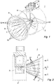
- the invention relates to an air intake assembly 1 for an automobile engine.
- the air intake assembly 1 comprises an air intake pipe 2, a flowmeter 3 and a device 5 for orienting an air flow l positioned upstream of the flowmeter 3 with respect to the direction of circulation of the air flow 1 in the pipe 2.
- the orientation device 5 can, for example, be made of plastic material.
- the orientation device 5 has a conical body 7 with an upstream opening 8 and a downstream opening 9.
- the conical body 7 has a plurality of baffles 10 elastically movable relative to the conical body 7.
- the deflectors 10 are separated by slots 12.
- the deflectors 10 are molded with the conical body 7.
- the deflectors 10 can occupy a multitude of positions between a first and a second extreme position.
- the movement of the deflectors 10 makes it possible to vary the downstream opening 9 of the conical body 7.
- the section of the downstream opening 9 changes between a minimum when the deflectors 10 are in the first extreme position and a maximum when the deflectors 10 are in the second extreme position.
- the function of the downstream opening 9 will be detailed below. According to the example presented here, in the absence of a sufficient air flow, the elasticity of the connection between the deflectors 10 and the conical body 7 maintains the deflectors 10 in the first extreme position.
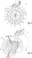
- the orientation device 5 comprises a conical body 7.
- the conical body 7 has a plurality of openings 20.
- the openings 20 have different geometries and surfaces.
- the conical body 7 has a first series of openings 20a, positioned in an upstream region and a second series of openings 20b positioned in a downstream region near the downstream opening 9.
- the openings 20b of the second series each cover a larger area than the openings 20a of the first series.
- the difference in surface area between the openings 20a of the first series and the openings 20b of the second series allows the guide device 5 according to the second embodiment to have variable permeability.
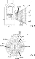
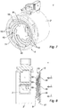
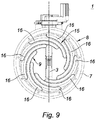
- the guide means the orientation device 5 comprises a diaphragm 15.
- the diaphragm is formed of a series of blades 16 retained in a ring 17.
- the blades 16 are resiliently biased towards a position of minimum opening of the diaphragm 15 , and these move apart to open the diaphragm 15 under the pressure of the air flow.
- the diaphragm 15 has a substantially conical geometry.
- the diaphragm 15 has a downstream opening 9, the section of which varies between a maximum when the diaphragm 15 is in the maximum open position and a minimum when the diaphragm 15 is in the minimum open position.
- the orientation device 5 may have a diameter equivalent to the diameter of the pipe 2, in order to be mounted adjusted in the pipe 2. This technical arrangement makes it possible to guarantee that all of the air flow l passes through the orientation device 5.
- the invention also relates to a method for measuring the flow rate of an air flow 1 circulating in an air intake assembly 1.
- Step (b) can comprise a phase of maintaining a minimum permeability, or of reducing the permeability, for a flow rate, called low flow rate, of between 1 g / s and 10 g / s, in order to concentrate the flow towards the flowmeter and increase the speed of the air flow.
- Step (b) can comprise a phase of increasing the permeability for a flow rate, called high flow rate, of between 30 g / s and 250 g / s, in order to reduce the pressure drops.
- the deflectors 10 reduce the downstream opening 9 to concentrate the air flow l on the flowmeter 3 and increase its speed. This technical arrangement allows the flowmeter 3 to perform a precise measurement of the flow rate of the air flow 1, when the latter flows at a low flow rate.
- the air flow l when the air flow l has a low flow rate, the air flow l flows mainly through the downstream opening 9 and through the openings 20b of the second series of openings 20. Thus , the air flow l is focused on the flowmeter 3 and is not slowed down.
- the diaphragm 15 when the air flow 1 has a low flow rate, the diaphragm 15 reduces the downstream opening 9 to concentrate the air flow 1 on the flow meter 3 and increase its speed.
- This technical arrangement allows the flowmeter 3 to perform a precise measurement of the flow rate of the air flow 1, when the latter flows at a low flow rate.
- the pressure of the air flow separates the deflectors 10 which open the downstream opening 9 to the maximum, to allow a fluid flow of the air flow.
- air flow l reducing pressure drops.
- the air flow l when the air flow l has a high flow rate, the air flow l passes through all of the openings 20 and the downstream opening 9. Thus the air flow l is not idle, which reduces pressure drops.
- the pressure of the air flow l on the diaphragm 15 opens up the downstream opening 9 to the maximum, to allow a fluid flow of the air flow. l by reducing pressure drops.
- the invention provides an air intake assembly for an automobile engine which makes it possible to precisely measure the flow rate of the air flow over the whole of the air flow range of the operation of the engine.
Landscapes
- Engineering & Computer Science (AREA)
- Chemical & Material Sciences (AREA)
- Combustion & Propulsion (AREA)
- Mechanical Engineering (AREA)
- General Engineering & Computer Science (AREA)
- Physics & Mathematics (AREA)
- Fluid Mechanics (AREA)
- Analytical Chemistry (AREA)
- General Physics & Mathematics (AREA)
- Measuring Volume Flow (AREA)
Claims (10)
- Lufteinlassanordnung (1) für einen Kraftfahrzeugmotor, umfassend ein Lufteinlassrohr (2), einen Durchflussmesser (3) und eine Vorrichtung zur Ausrichtung (5) eines Luftstroms, die stromaufwärts von dem Durchflussmesser (3) in Bezug auf die Umlaufrichtung des Luftstroms (l) in dem Rohr (2) positioniert ist, wobei die Vorrichtung zur Ausrichtung (5) des Luftstroms (l) angepasst ist, um den Luftstrom (l) zu dem Durchflussmesser (3) zu leiten, dadurch gekennzeichnet, dass die Vorrichtung zur Ausrichtung (5) des Luftstroms (l) eine variable Durchlässigkeit aufweist, um die Geschwindigkeit des Luftstroms (l) zu regeln.
- Lufteinlassanordnung (1) nach Anspruch 1, dadurch gekennzeichnet, dass die Vorrichtung zur Ausrichtung (5) eine konische Form mit einer stromaufwärtigen Öffnung (8) und einer stromabwärtigen Öffnung (9) aufweist, um den Luftstrom (l) auf den Durchflussmesser (3) zu fokussieren.
- Lufteinlassanordnung (1) nach Anspruch 2, dadurch gekennzeichnet, dass die Vorrichtung zur Ausrichtung (5) einen konischen Körper (7) aufweist, der eine Vielzahl von Abweisern (10) umfasst, die in Bezug auf den konischen Körper (7) elastisch beweglich sind, wobei die Abweiser (10) angepasst sind, um unter dem Druck des Luftstroms (l) bewegt zu werden, um die Durchlässigkeit der Vorrichtung zur Ausrichtung (5) variieren zu lassen.
- Lufteinlassanordnung (1) nach Anspruch 3, dadurch gekennzeichnet, dass der konische Körper (7) Schlitze (12) aufweist, die jeden Abweiser (10) trennen, wobei die Schlitze (12) die Bewegung jedes Abweisers (10) ermöglichen und eine Variation der Durchlässigkeit der Vorrichtung zur Ausrichtung (5) ermöglichen.
- Lufteinlassanordnung (1) nach Anspruch 2, dadurch gekennzeichnet, dass die Vorrichtung zur Ausrichtung (5) einen konischen Körper (7) umfasst, der eine Vielzahl von Öffnungen (20) aufweist, die unterschiedliche Formen und Oberflächen aufweisen.
- Lufteinlassanordnung (1) nach Anspruch 5, dadurch gekennzeichnet, dass der konische Körper (7) eine erste Reihe von Öffnungen (20a) aufweist, die in einem stromaufwärtigen Bereich positioniert sind, und eine zweite Reihe von Öffnungen (20b), die in einem stromabwärtigen Bereich positioniert sind, wobei die Öffnungen (20b) der zweiten Reihe jeweils eine Oberfläche aufweisen, die höher liegt als die Oberfläche jeder Öffnung (20a) der ersten Reihe.
- Lufteinlassanordnung (1) nach Anspruch 2, dadurch gekennzeichnet, dass die Vorrichtung zur Ausrichtung (5) eine Blende (15) in konischer Form umfasst, die angepasst ist, um die stromabwärtige Öffnung (9) variieren zu lassen.
- Verfahren zum Messen des Durchflusses eines Luftstroms (l), der in einer Lufteinlassanordnung (1) nach einem der Ansprüche 1 bis 7 zirkuliert, dadurch gekennzeichnet, dass es folgende Schritte umfasst:- (a) Zirkulieren eines Luftstroms (l), der einen Durchfluss aufweist, in dem Rohr (2);- (b) Variieren der Durchlässigkeit der Vorrichtung zur Ausrichtung (5) je nach Durchfluss des Luftstroms (l), der in dem Rohr (2) zirkuliert, um die Geschwindigkeit des Luftstroms (l) zu regeln und des Luftstrom (l) zu dem Durchflussmesser (3) auszurichten;- (c) Messen des Durchflusses mittels des Durchflussmessers (3).
- Verfahren nach Anspruch 8, dadurch gekennzeichnet, dass der Schritt (b) eine Phase des Aufrechterhaltens einer minimalen Durchlässigkeit oder des Verringerns der Durchlässigkeit für einen Durchfluss, so genannten niedrigen Durchfluss, umfasst, der zwischen 1 g/s und 10 g/s beträgt, um den Luftstrom (l) zu dem Durchflussmesser (3) zu konzentrieren und die Geschwindigkeit des Luftstroms (l) zu erhöhen.
- Verfahren nach Anspruch 9, dadurch gekennzeichnet, dass der Schritt (b) eine Phase des Erhöhens der Durchlässigkeit für einen Durchfluss, so genannten hohen Durchfluss, umfasst, der zwischen 30 g/s und 250 g/s beträgt, um die Druckverluste zu mindern.
Applications Claiming Priority (2)
| Application Number | Priority Date | Filing Date | Title |
|---|---|---|---|
| FR1759414A FR3072132B1 (fr) | 2017-10-09 | 2017-10-09 | Ensemble d'admission d'air |
| PCT/FR2018/052401 WO2019073142A1 (fr) | 2017-10-09 | 2018-09-28 | Ensemble d'admission d'air |
Publications (2)
| Publication Number | Publication Date |
|---|---|
| EP3669065A1 EP3669065A1 (de) | 2020-06-24 |
| EP3669065B1 true EP3669065B1 (de) | 2021-04-07 |
Family
ID=60515643
Family Applications (1)
| Application Number | Title | Priority Date | Filing Date |
|---|---|---|---|
| EP18793246.2A Active EP3669065B1 (de) | 2017-10-09 | 2018-09-28 | Lufteinlassanordnung |
Country Status (5)
| Country | Link |
|---|---|
| US (1) | US11193459B2 (de) |
| EP (1) | EP3669065B1 (de) |
| ES (1) | ES2878304T3 (de) |
| FR (1) | FR3072132B1 (de) |
| WO (1) | WO2019073142A1 (de) |
Family Cites Families (8)
| Publication number | Priority date | Publication date | Assignee | Title |
|---|---|---|---|---|
| US4131441A (en) * | 1976-11-17 | 1978-12-26 | Fram Corporation | Multi-size rain hood |
| FR2738901B1 (fr) | 1995-09-20 | 1997-11-21 | Abb Flakt | Dispositif regulateur de debit d'air perfectionne |
| US5749342A (en) * | 1996-09-03 | 1998-05-12 | Chao; Raymond | Moveable aperture for alteration of intake manifold cross sectional area |
| ES2136006B1 (es) * | 1996-10-22 | 2000-05-16 | Torralba Gimeno Cesar | Compensador de vacio para motores de explosion. |
| ES2234372B1 (es) * | 2002-11-05 | 2006-10-01 | Cesar Torralba Gimeno | Compensador de vacio para motores de explosion. |
| US6913001B2 (en) * | 2003-06-18 | 2005-07-05 | Visteon Global Technologies, Inc. | Hydrocarbon adsorbing device for adsorbing backflow of hydrocarbons from a vehicle engine |
| US10480663B2 (en) * | 2015-07-13 | 2019-11-19 | True Blue Motorsport | Continuously concentric valve with movable flow guides |
| US10584719B2 (en) * | 2017-09-11 | 2020-03-10 | Ford Global Technologies, Llc | Systems and method for a variable inlet device of a compressor |
-
2017
- 2017-10-09 FR FR1759414A patent/FR3072132B1/fr not_active Expired - Fee Related
-
2018
- 2018-09-28 WO PCT/FR2018/052401 patent/WO2019073142A1/fr not_active Ceased
- 2018-09-28 EP EP18793246.2A patent/EP3669065B1/de active Active
- 2018-09-28 ES ES18793246T patent/ES2878304T3/es active Active
- 2018-09-28 US US16/754,678 patent/US11193459B2/en active Active
Non-Patent Citations (1)
| Title |
|---|
| None * |
Also Published As
| Publication number | Publication date |
|---|---|
| FR3072132A1 (fr) | 2019-04-12 |
| US20200355146A1 (en) | 2020-11-12 |
| US11193459B2 (en) | 2021-12-07 |
| FR3072132B1 (fr) | 2019-09-27 |
| ES2878304T3 (es) | 2021-11-18 |
| WO2019073142A1 (fr) | 2019-04-18 |
| EP3669065A1 (de) | 2020-06-24 |
Similar Documents
| Publication | Publication Date | Title |
|---|---|---|
| CA2721423C (fr) | Injection d'air dans la veine d'un compresseur de turbomachine | |
| EP3669065B1 (de) | Lufteinlassanordnung | |
| WO2013076412A1 (fr) | Vanne de controle pour systeme de recirculation des gaz d'echappement d'un moteur a combustion interne | |
| EP3067547B1 (de) | Eingangsanschluss eines turbokompressors mit agr-gasverteiler | |
| EP2108788B1 (de) | Verbrennungsmotor mit abgefasten Einlassleitungen | |
| FR2922939A1 (fr) | Turbomachine comprenant un diffuseur | |
| WO2015128069A1 (fr) | Procede de determination de la pression atmospherique lors du fonctionnement, dans un etat de charge partielle, d'un moteur turbocompressee | |
| CA2857927A1 (fr) | Tuyere convergente-divergente de turbomachine | |
| FR3074523A1 (fr) | Dispositif compact de purification et de recirculation de gaz d'echappement | |
| EP1215377B1 (de) | Gaseinlasssystem für einen Brennkammer, dessen Einlasskanal eine Rille aufweist | |
| FR2893988A1 (fr) | Moteur a combustion interne comprenant un circuit de recirculation de gaz d'echappement simplifie | |
| FR2879249A1 (fr) | Dispositif de suralimentation et de stratification de gaz d'echappement recycles pour moteur a combustion interne, notamment pour vehicule automobile, et procede associe. | |
| FR3018854A3 (fr) | Deflecteur integre au carter de turbocompresseur | |
| FR2910541A1 (fr) | Systeme d'admission de gaz pour la generation d'ecoulement de rotation energetique de tumble | |
| FR3009023A1 (fr) | Boitier papillon et moteur a combustion interne comprenant un tel boitier papillon | |
| EP1640567A1 (de) | Motor mit einem Zylinderkopf, mit mindestens einem Gas-Einlasskanal | |
| FR3130882A1 (fr) | Groupe moteur à combustion interne comportant un circuit d’échappement avec un capteur de concentration d’oxydes d’azote | |
| FR3072130B1 (fr) | Ensemble d'admission d'air | |
| EP1914400A1 (de) | Abgasanlage mit einem Katalysator und einer Temperatursonde | |
| EP1219797A1 (de) | Gaseinlasssystem in einer Brennkammer mit Strömungsablenkungsmitteln | |
| EP4240650A1 (de) | Gondellufteinlass für eine flugzeugantriebsanordnung zur förderung einer schubumkehrphase | |
| EP1591642A1 (de) | Einlasssystem mit Öffnung, die eine Einkerbung zur Übertragung einer Swirl-Bewegung auf die Einlassgase beinhaltet | |
| FR2867512A1 (fr) | Moteur a combustion interne et siege de soupape prevu pour produire un mouvement tourbillonnaire | |
| FR3103515A1 (fr) | Siege de soupape d’echappement presentant un profil aerodynamique optimise | |
| EP1431541A1 (de) | Brennkraftmaschine mit Mitteln zur Variation der Drallintensität |
Legal Events
| Date | Code | Title | Description |
|---|---|---|---|
| STAA | Information on the status of an ep patent application or granted ep patent |
Free format text: STATUS: UNKNOWN |
|
| STAA | Information on the status of an ep patent application or granted ep patent |
Free format text: STATUS: THE INTERNATIONAL PUBLICATION HAS BEEN MADE |
|
| PUAI | Public reference made under article 153(3) epc to a published international application that has entered the european phase |
Free format text: ORIGINAL CODE: 0009012 |
|
| STAA | Information on the status of an ep patent application or granted ep patent |
Free format text: STATUS: REQUEST FOR EXAMINATION WAS MADE |
|
| 17P | Request for examination filed |
Effective date: 20200318 |
|
| AK | Designated contracting states |
Kind code of ref document: A1 Designated state(s): AL AT BE BG CH CY CZ DE DK EE ES FI FR GB GR HR HU IE IS IT LI LT LU LV MC MK MT NL NO PL PT RO RS SE SI SK SM TR |
|
| AX | Request for extension of the european patent |
Extension state: BA ME |
|
| RIN1 | Information on inventor provided before grant (corrected) |
Inventor name: DEMANGEOT, JEROME Inventor name: FACQ, GREGORY |
|
| GRAP | Despatch of communication of intention to grant a patent |
Free format text: ORIGINAL CODE: EPIDOSNIGR1 |
|
| STAA | Information on the status of an ep patent application or granted ep patent |
Free format text: STATUS: GRANT OF PATENT IS INTENDED |
|
| DAV | Request for validation of the european patent (deleted) | ||
| DAX | Request for extension of the european patent (deleted) | ||
| INTG | Intention to grant announced |
Effective date: 20201222 |
|
| GRAS | Grant fee paid |
Free format text: ORIGINAL CODE: EPIDOSNIGR3 |
|
| GRAA | (expected) grant |
Free format text: ORIGINAL CODE: 0009210 |
|
| STAA | Information on the status of an ep patent application or granted ep patent |
Free format text: STATUS: THE PATENT HAS BEEN GRANTED |
|
| AK | Designated contracting states |
Kind code of ref document: B1 Designated state(s): AL AT BE BG CH CY CZ DE DK EE ES FI FR GB GR HR HU IE IS IT LI LT LU LV MC MK MT NL NO PL PT RO RS SE SI SK SM TR |
|
| REG | Reference to a national code |
Ref country code: GB Ref legal event code: FG4D Free format text: NOT ENGLISH |
|
| REG | Reference to a national code |
Ref country code: AT Ref legal event code: REF Ref document number: 1379994 Country of ref document: AT Kind code of ref document: T Effective date: 20210415 Ref country code: CH Ref legal event code: EP |
|
| REG | Reference to a national code |
Ref country code: DE Ref legal event code: R096 Ref document number: 602018015338 Country of ref document: DE |
|
| REG | Reference to a national code |
Ref country code: IE Ref legal event code: FG4D Free format text: LANGUAGE OF EP DOCUMENT: FRENCH |
|
| REG | Reference to a national code |
Ref country code: LT Ref legal event code: MG9D |
|
| REG | Reference to a national code |
Ref country code: NL Ref legal event code: MP Effective date: 20210407 Ref country code: AT Ref legal event code: MK05 Ref document number: 1379994 Country of ref document: AT Kind code of ref document: T Effective date: 20210407 |
|
| PG25 | Lapsed in a contracting state [announced via postgrant information from national office to epo] |
Ref country code: HR Free format text: LAPSE BECAUSE OF FAILURE TO SUBMIT A TRANSLATION OF THE DESCRIPTION OR TO PAY THE FEE WITHIN THE PRESCRIBED TIME-LIMIT Effective date: 20210407 Ref country code: LT Free format text: LAPSE BECAUSE OF FAILURE TO SUBMIT A TRANSLATION OF THE DESCRIPTION OR TO PAY THE FEE WITHIN THE PRESCRIBED TIME-LIMIT Effective date: 20210407 Ref country code: FI Free format text: LAPSE BECAUSE OF FAILURE TO SUBMIT A TRANSLATION OF THE DESCRIPTION OR TO PAY THE FEE WITHIN THE PRESCRIBED TIME-LIMIT Effective date: 20210407 Ref country code: NL Free format text: LAPSE BECAUSE OF FAILURE TO SUBMIT A TRANSLATION OF THE DESCRIPTION OR TO PAY THE FEE WITHIN THE PRESCRIBED TIME-LIMIT Effective date: 20210407 Ref country code: AT Free format text: LAPSE BECAUSE OF FAILURE TO SUBMIT A TRANSLATION OF THE DESCRIPTION OR TO PAY THE FEE WITHIN THE PRESCRIBED TIME-LIMIT Effective date: 20210407 Ref country code: BG Free format text: LAPSE BECAUSE OF FAILURE TO SUBMIT A TRANSLATION OF THE DESCRIPTION OR TO PAY THE FEE WITHIN THE PRESCRIBED TIME-LIMIT Effective date: 20210707 |
|
| REG | Reference to a national code |
Ref country code: ES Ref legal event code: FG2A Ref document number: 2878304 Country of ref document: ES Kind code of ref document: T3 Effective date: 20211118 |
|
| PG25 | Lapsed in a contracting state [announced via postgrant information from national office to epo] |
Ref country code: PT Free format text: LAPSE BECAUSE OF FAILURE TO SUBMIT A TRANSLATION OF THE DESCRIPTION OR TO PAY THE FEE WITHIN THE PRESCRIBED TIME-LIMIT Effective date: 20210809 Ref country code: SE Free format text: LAPSE BECAUSE OF FAILURE TO SUBMIT A TRANSLATION OF THE DESCRIPTION OR TO PAY THE FEE WITHIN THE PRESCRIBED TIME-LIMIT Effective date: 20210407 Ref country code: RS Free format text: LAPSE BECAUSE OF FAILURE TO SUBMIT A TRANSLATION OF THE DESCRIPTION OR TO PAY THE FEE WITHIN THE PRESCRIBED TIME-LIMIT Effective date: 20210407 Ref country code: LV Free format text: LAPSE BECAUSE OF FAILURE TO SUBMIT A TRANSLATION OF THE DESCRIPTION OR TO PAY THE FEE WITHIN THE PRESCRIBED TIME-LIMIT Effective date: 20210407 Ref country code: NO Free format text: LAPSE BECAUSE OF FAILURE TO SUBMIT A TRANSLATION OF THE DESCRIPTION OR TO PAY THE FEE WITHIN THE PRESCRIBED TIME-LIMIT Effective date: 20210707 Ref country code: PL Free format text: LAPSE BECAUSE OF FAILURE TO SUBMIT A TRANSLATION OF THE DESCRIPTION OR TO PAY THE FEE WITHIN THE PRESCRIBED TIME-LIMIT Effective date: 20210407 Ref country code: IS Free format text: LAPSE BECAUSE OF FAILURE TO SUBMIT A TRANSLATION OF THE DESCRIPTION OR TO PAY THE FEE WITHIN THE PRESCRIBED TIME-LIMIT Effective date: 20210807 Ref country code: GR Free format text: LAPSE BECAUSE OF FAILURE TO SUBMIT A TRANSLATION OF THE DESCRIPTION OR TO PAY THE FEE WITHIN THE PRESCRIBED TIME-LIMIT Effective date: 20210708 |
|
| REG | Reference to a national code |
Ref country code: DE Ref legal event code: R097 Ref document number: 602018015338 Country of ref document: DE |
|
| PG25 | Lapsed in a contracting state [announced via postgrant information from national office to epo] |
Ref country code: SK Free format text: LAPSE BECAUSE OF FAILURE TO SUBMIT A TRANSLATION OF THE DESCRIPTION OR TO PAY THE FEE WITHIN THE PRESCRIBED TIME-LIMIT Effective date: 20210407 Ref country code: EE Free format text: LAPSE BECAUSE OF FAILURE TO SUBMIT A TRANSLATION OF THE DESCRIPTION OR TO PAY THE FEE WITHIN THE PRESCRIBED TIME-LIMIT Effective date: 20210407 Ref country code: DK Free format text: LAPSE BECAUSE OF FAILURE TO SUBMIT A TRANSLATION OF THE DESCRIPTION OR TO PAY THE FEE WITHIN THE PRESCRIBED TIME-LIMIT Effective date: 20210407 Ref country code: CZ Free format text: LAPSE BECAUSE OF FAILURE TO SUBMIT A TRANSLATION OF THE DESCRIPTION OR TO PAY THE FEE WITHIN THE PRESCRIBED TIME-LIMIT Effective date: 20210407 Ref country code: RO Free format text: LAPSE BECAUSE OF FAILURE TO SUBMIT A TRANSLATION OF THE DESCRIPTION OR TO PAY THE FEE WITHIN THE PRESCRIBED TIME-LIMIT Effective date: 20210407 Ref country code: SM Free format text: LAPSE BECAUSE OF FAILURE TO SUBMIT A TRANSLATION OF THE DESCRIPTION OR TO PAY THE FEE WITHIN THE PRESCRIBED TIME-LIMIT Effective date: 20210407 |
|
| PLBE | No opposition filed within time limit |
Free format text: ORIGINAL CODE: 0009261 |
|
| STAA | Information on the status of an ep patent application or granted ep patent |
Free format text: STATUS: NO OPPOSITION FILED WITHIN TIME LIMIT |
|
| 26N | No opposition filed |
Effective date: 20220110 |
|
| REG | Reference to a national code |
Ref country code: CH Ref legal event code: PL |
|
| REG | Reference to a national code |
Ref country code: BE Ref legal event code: MM Effective date: 20210930 |
|
| PG25 | Lapsed in a contracting state [announced via postgrant information from national office to epo] |
Ref country code: IS Free format text: LAPSE BECAUSE OF FAILURE TO SUBMIT A TRANSLATION OF THE DESCRIPTION OR TO PAY THE FEE WITHIN THE PRESCRIBED TIME-LIMIT Effective date: 20210807 Ref country code: MC Free format text: LAPSE BECAUSE OF FAILURE TO SUBMIT A TRANSLATION OF THE DESCRIPTION OR TO PAY THE FEE WITHIN THE PRESCRIBED TIME-LIMIT Effective date: 20210407 Ref country code: AL Free format text: LAPSE BECAUSE OF FAILURE TO SUBMIT A TRANSLATION OF THE DESCRIPTION OR TO PAY THE FEE WITHIN THE PRESCRIBED TIME-LIMIT Effective date: 20210407 |
|
| PG25 | Lapsed in a contracting state [announced via postgrant information from national office to epo] |
Ref country code: LU Free format text: LAPSE BECAUSE OF NON-PAYMENT OF DUE FEES Effective date: 20210928 Ref country code: IT Free format text: LAPSE BECAUSE OF FAILURE TO SUBMIT A TRANSLATION OF THE DESCRIPTION OR TO PAY THE FEE WITHIN THE PRESCRIBED TIME-LIMIT Effective date: 20210407 Ref country code: IE Free format text: LAPSE BECAUSE OF NON-PAYMENT OF DUE FEES Effective date: 20210928 Ref country code: BE Free format text: LAPSE BECAUSE OF NON-PAYMENT OF DUE FEES Effective date: 20210930 |
|
| PG25 | Lapsed in a contracting state [announced via postgrant information from national office to epo] |
Ref country code: LI Free format text: LAPSE BECAUSE OF NON-PAYMENT OF DUE FEES Effective date: 20210930 Ref country code: CH Free format text: LAPSE BECAUSE OF NON-PAYMENT OF DUE FEES Effective date: 20210930 |
|
| GBPC | Gb: european patent ceased through non-payment of renewal fee |
Effective date: 20220928 |
|
| PG25 | Lapsed in a contracting state [announced via postgrant information from national office to epo] |
Ref country code: CY Free format text: LAPSE BECAUSE OF FAILURE TO SUBMIT A TRANSLATION OF THE DESCRIPTION OR TO PAY THE FEE WITHIN THE PRESCRIBED TIME-LIMIT Effective date: 20210407 |
|
| PG25 | Lapsed in a contracting state [announced via postgrant information from national office to epo] |
Ref country code: HU Free format text: LAPSE BECAUSE OF FAILURE TO SUBMIT A TRANSLATION OF THE DESCRIPTION OR TO PAY THE FEE WITHIN THE PRESCRIBED TIME-LIMIT; INVALID AB INITIO Effective date: 20180928 |
|
| PG25 | Lapsed in a contracting state [announced via postgrant information from national office to epo] |
Ref country code: GB Free format text: LAPSE BECAUSE OF NON-PAYMENT OF DUE FEES Effective date: 20220928 |
|
| PGFP | Annual fee paid to national office [announced via postgrant information from national office to epo] |
Ref country code: DE Payment date: 20230915 Year of fee payment: 6 |
|
| PGFP | Annual fee paid to national office [announced via postgrant information from national office to epo] |
Ref country code: ES Payment date: 20231009 Year of fee payment: 6 |
|
| PG25 | Lapsed in a contracting state [announced via postgrant information from national office to epo] |
Ref country code: MK Free format text: LAPSE BECAUSE OF FAILURE TO SUBMIT A TRANSLATION OF THE DESCRIPTION OR TO PAY THE FEE WITHIN THE PRESCRIBED TIME-LIMIT Effective date: 20210407 |
|
| PG25 | Lapsed in a contracting state [announced via postgrant information from national office to epo] |
Ref country code: MT Free format text: LAPSE BECAUSE OF FAILURE TO SUBMIT A TRANSLATION OF THE DESCRIPTION OR TO PAY THE FEE WITHIN THE PRESCRIBED TIME-LIMIT Effective date: 20210407 |
|
| REG | Reference to a national code |
Ref country code: DE Ref legal event code: R119 Ref document number: 602018015338 Country of ref document: DE |
|
| PG25 | Lapsed in a contracting state [announced via postgrant information from national office to epo] |
Ref country code: DE Free format text: LAPSE BECAUSE OF NON-PAYMENT OF DUE FEES Effective date: 20250401 |
|
| PGFP | Annual fee paid to national office [announced via postgrant information from national office to epo] |
Ref country code: FR Payment date: 20250731 Year of fee payment: 8 |
|
| REG | Reference to a national code |
Ref country code: ES Ref legal event code: FD2A Effective date: 20251031 |
|
| PG25 | Lapsed in a contracting state [announced via postgrant information from national office to epo] |
Ref country code: TR Free format text: LAPSE BECAUSE OF FAILURE TO SUBMIT A TRANSLATION OF THE DESCRIPTION OR TO PAY THE FEE WITHIN THE PRESCRIBED TIME-LIMIT Effective date: 20210407 |
|
| PG25 | Lapsed in a contracting state [announced via postgrant information from national office to epo] |
Ref country code: ES Free format text: LAPSE BECAUSE OF NON-PAYMENT OF DUE FEES Effective date: 20240929 |