EP3668775B1 - Steering column engineered tape - Google Patents
Steering column engineered tape Download PDFInfo
- Publication number
- EP3668775B1 EP3668775B1 EP18755778.0A EP18755778A EP3668775B1 EP 3668775 B1 EP3668775 B1 EP 3668775B1 EP 18755778 A EP18755778 A EP 18755778A EP 3668775 B1 EP3668775 B1 EP 3668775B1
- Authority
- EP
- European Patent Office
- Prior art keywords
- tape
- section
- box rocker
- steering column
- rocker
- Prior art date
- Legal status (The legal status is an assumption and is not a legal conclusion. Google has not performed a legal analysis and makes no representation as to the accuracy of the status listed.)
- Active
Links
Images




Classifications
-
- F—MECHANICAL ENGINEERING; LIGHTING; HEATING; WEAPONS; BLASTING
- F16—ENGINEERING ELEMENTS AND UNITS; GENERAL MEASURES FOR PRODUCING AND MAINTAINING EFFECTIVE FUNCTIONING OF MACHINES OR INSTALLATIONS; THERMAL INSULATION IN GENERAL
- F16C—SHAFTS; FLEXIBLE SHAFTS; ELEMENTS OR CRANKSHAFT MECHANISMS; ROTARY BODIES OTHER THAN GEARING ELEMENTS; BEARINGS
- F16C3/00—Shafts; Axles; Cranks; Eccentrics
- F16C3/02—Shafts; Axles
- F16C3/03—Shafts; Axles telescopic
-
- B—PERFORMING OPERATIONS; TRANSPORTING
- B62—LAND VEHICLES FOR TRAVELLING OTHERWISE THAN ON RAILS
- B62D—MOTOR VEHICLES; TRAILERS
- B62D1/00—Steering controls, i.e. means for initiating a change of direction of the vehicle
- B62D1/02—Steering controls, i.e. means for initiating a change of direction of the vehicle vehicle-mounted
- B62D1/16—Steering columns
- B62D1/18—Steering columns yieldable or adjustable, e.g. tiltable
- B62D1/187—Steering columns yieldable or adjustable, e.g. tiltable with tilt adjustment; with tilt and axial adjustment
- B62D1/189—Steering columns yieldable or adjustable, e.g. tiltable with tilt adjustment; with tilt and axial adjustment the entire column being tiltable as a unit
-
- B—PERFORMING OPERATIONS; TRANSPORTING
- B62—LAND VEHICLES FOR TRAVELLING OTHERWISE THAN ON RAILS
- B62D—MOTOR VEHICLES; TRAILERS
- B62D1/00—Steering controls, i.e. means for initiating a change of direction of the vehicle
- B62D1/02—Steering controls, i.e. means for initiating a change of direction of the vehicle vehicle-mounted
- B62D1/16—Steering columns
- B62D1/18—Steering columns yieldable or adjustable, e.g. tiltable
- B62D1/181—Steering columns yieldable or adjustable, e.g. tiltable with power actuated adjustment, e.g. with position memory
-
- B—PERFORMING OPERATIONS; TRANSPORTING
- B62—LAND VEHICLES FOR TRAVELLING OTHERWISE THAN ON RAILS
- B62D—MOTOR VEHICLES; TRAILERS
- B62D1/00—Steering controls, i.e. means for initiating a change of direction of the vehicle
- B62D1/02—Steering controls, i.e. means for initiating a change of direction of the vehicle vehicle-mounted
- B62D1/16—Steering columns
- B62D1/18—Steering columns yieldable or adjustable, e.g. tiltable
- B62D1/185—Steering columns yieldable or adjustable, e.g. tiltable adjustable by axial displacement, e.g. telescopically
-
- F—MECHANICAL ENGINEERING; LIGHTING; HEATING; WEAPONS; BLASTING
- F16—ENGINEERING ELEMENTS AND UNITS; GENERAL MEASURES FOR PRODUCING AND MAINTAINING EFFECTIVE FUNCTIONING OF MACHINES OR INSTALLATIONS; THERMAL INSULATION IN GENERAL
- F16C—SHAFTS; FLEXIBLE SHAFTS; ELEMENTS OR CRANKSHAFT MECHANISMS; ROTARY BODIES OTHER THAN GEARING ELEMENTS; BEARINGS
- F16C2204/00—Metallic materials; Alloys
- F16C2204/26—Alloys based on magnesium
-
- F—MECHANICAL ENGINEERING; LIGHTING; HEATING; WEAPONS; BLASTING
- F16—ENGINEERING ELEMENTS AND UNITS; GENERAL MEASURES FOR PRODUCING AND MAINTAINING EFFECTIVE FUNCTIONING OF MACHINES OR INSTALLATIONS; THERMAL INSULATION IN GENERAL
- F16C—SHAFTS; FLEXIBLE SHAFTS; ELEMENTS OR CRANKSHAFT MECHANISMS; ROTARY BODIES OTHER THAN GEARING ELEMENTS; BEARINGS
- F16C2204/00—Metallic materials; Alloys
- F16C2204/60—Ferrous alloys, e.g. steel alloys
-
- F—MECHANICAL ENGINEERING; LIGHTING; HEATING; WEAPONS; BLASTING
- F16—ENGINEERING ELEMENTS AND UNITS; GENERAL MEASURES FOR PRODUCING AND MAINTAINING EFFECTIVE FUNCTIONING OF MACHINES OR INSTALLATIONS; THERMAL INSULATION IN GENERAL
- F16C—SHAFTS; FLEXIBLE SHAFTS; ELEMENTS OR CRANKSHAFT MECHANISMS; ROTARY BODIES OTHER THAN GEARING ELEMENTS; BEARINGS
- F16C2220/00—Shaping
- F16C2220/80—Shaping by separating parts, e.g. by severing, cracking
- F16C2220/82—Shaping by separating parts, e.g. by severing, cracking by cutting
-
- F—MECHANICAL ENGINEERING; LIGHTING; HEATING; WEAPONS; BLASTING
- F16—ENGINEERING ELEMENTS AND UNITS; GENERAL MEASURES FOR PRODUCING AND MAINTAINING EFFECTIVE FUNCTIONING OF MACHINES OR INSTALLATIONS; THERMAL INSULATION IN GENERAL
- F16C—SHAFTS; FLEXIBLE SHAFTS; ELEMENTS OR CRANKSHAFT MECHANISMS; ROTARY BODIES OTHER THAN GEARING ELEMENTS; BEARINGS
- F16C2226/00—Joining parts; Fastening; Assembling or mounting parts
- F16C2226/30—Material joints
- F16C2226/40—Material joints with adhesive
Definitions
- the present disclosure relates generally to a steering column for a motor vehicle and more specifically to a steering column assembly that incorporates tape between an inner diameter of a box rocker and an outer diameter of a column jacket.
- Steering columns in motor vehicles are generally adjustable so as to be able to adapt the position of the steering wheel to requirements of different drivers.
- the vehicle steering wheel is mounted to a telescoping column jacket that is supported within a box rocker.
- at least portions of an outer diameter surface of the column jacket can be caused to ride along at least portions of an inner diameter of the box rocker during telescopic adjustment. It is desirable to mitigate wear between the column jacket and the box rocker and to further inhibit debris such as shavings that may discharged onto the mating surfaces.
- rigid sleeves such as those formed of plastic or metal
- a steering column assembly for a motor vehicle constructed in accordance to the present disclosure includes a box rocker, a column jacket and a first section of tape.
- the box rocker has a rocker body including a box rocker inner surface that defines a box rocker bore.
- the box rocker is configured to be fixed relative to the motor vehicle in an assembled position.
- the column jacket is configured to be slidably received into the box rocker bore.
- the column jacket has a column jacket outer diameter including an outer surface that opposes the box rocker inner surface.
- the first section of tape is disposed between the box rocker inner surface and the column jacket outer surface.
- the first section of tape is at least partially adhered to the box rocker inner surface.
- the first section of tape is further adhered to a face surface of the box rocker body.
- the first section of tape is positioned generally around an upper circumference of the box rocker bore.
- the first section of tape is configured to compress between 20% and 25%.
- the column jacket further comprises an inner jacket tube that opposes the first section of tape.
- the box rocker includes a fluted section provided by a plurality of radially stepped in surfaces and a plurality of radially stepped out surfaces.
- the section of tape is positioned on at least two adjacent radially stepped in surfaces of the plurality of radially stepped in surfaces.
- the plurality of stepped in surfaces collectively provide the box rocker inner surface.
- the inner surface of the box rocker and the outer surface of the column jacket are substantially concentric.
- the column jacket is configured to translate within the box rocker bore. During translation, the outer surface of the column jacket is caused to slidably ride along the first section of tape disposed on the inner surface of the box rocker.
- the column jacket can be formed of steel.
- the box rocker can be formed of magnesium.
- the first section of tape has a thickness of between 0.05 mm and 0.5 mm, preferably between 0.1 mm and 0.2 mm and especially preferred between 0.12 mm and 0.18 mm.
- the first section of tape has one of acrylic or silicone pressure sensitive adhesive.
- the steering column assembly further comprises a second section of tape, distinct from the first section of tape and disposed between the box rocker inner surface and the column jacket outer surface.
- the first and second sections of tape are of different geometries having distinct footprints.
- the steering assembly can additionally include a third section of tape, distinct from the first and second sections of tape and disposed between the box rocker inner surface and the column jacket outer surface.
- a method of assembling a column jacket relative to a box rocker of a steering column assembly for a motor vehicle is provided.
- a mating contact surface of the box rocker is identified.
- a first section of tape is disposed onto the inner surface of a box rocker at the contact surface.
- the column jacket is slidably inserted into a bore defined by the inner surface of the box rocker.
- An outer surface of the column jacket slidably advances along the first section of tape mitigating surface to surface contact between the column jacket and the box rocker.
- the first section of tape is cut from a roll or sheet of tape.
- the first section of tape corresponds to a desired area of the inner surface of the box rocker.
- Disposing the first section of tape can further comprise cutting slots into the tape to create tabs. The tabs are adhered to a face of the box rocker.
- the steering column assembly 10 generally includes a box rocker 12 having a bracket assembly 13, an electric motor assembly 14, a column jacket 16, a biasing mount assembly 18 and engineered tape 20, which can comprise any suitable tape that provides satisfactory compression and wear characteristics (see further explanation below).
- the bracket assembly 13 includes a first bracket 13a and a second bracket 13b.
- the electric motor assembly 14 includes a first electric motor 14a and a second electric motor 14b.
- the first electric motor 14a is coupled with a first worm of a first worm gear, wherein the first worm meshes a first worm wheel.
- the first worm wheel comprises a first bore with a first outer thread.
- a first spindle engages into the thread of the first bore, wherein the first spindle is coupled with a height adjustment mechanism to adjust the column jacket 16 and the box rocker 12 relative to the first bracket 13a.
- the second electric motor 14b is coupled with a second worm of a second worm gear, wherein the second worm meshes a second worm wheel.
- the second worm wheel comprises a second bore with a second outer thread.
- a second spindle engages into the thread of the second bore, wherein the second spindle is coupled with a length adjustment mechanism to adjust the column jacket 16 relative to the box rocker 12 along a longitudinal column jacket axis 60.
- the biasing mount assembly 18 includes a pair of biasing mounts 18a and 18b that are adjustably mounted on the box rocker 12 and configured to urge the column jacket 16 toward the engineered tape 20 disposed on an opposite side of the box rocker 12 as will be described in greater detail herein.
- the first and second brackets 13a and 13b are configured to accept fasteners for mounting the steering column assembly 10 relative to a vehicle.
- the first and second electric motors 14a and 14b are configured to alter an orientation of the box rocker 12 and column jacket 16 relative to a driver in a vehicle. It will be appreciated that the configuration of the motor assembly 14 and bracket assembly 13 is merely exemplary and other arrangements may be used for the steering column assembly 10 within the scope of the present disclosure.
- the column jacket 16 is configured to telescope relative to the box rocker 12 between the positions shown in FIG. 1 and FIG. 3 .
- the engineered tape 20 is positioned between the box rocker 12 and the column jacket 16 to mitigate wear between the box rocker 12 and column jacket 16 and to provide other benefits as explained below.
- the box rocker 12 comprises a rocker body 24 that includes a mounting bore 28 and generally defines a box rocker bore 30.
- the mounting bore 28 is configured to receive a mounting axle 31 that couples with the bracket 13a to facilitate mounting of the box rocker 12 to the vehicle.
- the box rocker bore 30 extends along a bore axis 32 and is generally defined by a fluted section 34 provided by a plurality of radially stepped in surfaces 36 and a plurality of radially stepped out surfaces 38.
- the plurality of stepped in surfaces 36 collectively provide a box rocker inner surface 40 along a box rocker inner diameter 42.
- the box rocker inner surface 40 slidably receives the column jacket 16 as will be understood below. While five stepped in surfaces 36 and four stepped out surfaces 38 are shown, it is appreciated that additional or fewer stepped in and out surfaces 36, 38 may be provided. It is further appreciated that the stepped in and out surfaces 36, 38 may take other geometries within the scope of the present disclosure. Moreover, it will be appreciated that the inner surface 40 may take on a continuous circumferential surface without any fluting.
- Both of the biasing mount assemblies 18a, 18b include a pad 50a, 50b; a biasing member 52a, 52b and a screw 54a, 54b.
- the biasing members 52a and 52b bias the respective pads 50a and 50b into the column jacket outer diameter.
- the biasing mount assemblies 18 locate into arc shaped screw holes 56a and 56b defined in the column jacket 16.
- the screws 54a and 54b facilitate mounting of the biasing mount assemblies 18a and 18b to the column jacket 16.
- the column jacket 16 generally includes an inner jacket tube 58 and a steering shaft 59.
- the column jacket 16 extends along a longitudinal column jacket axis 60.
- the steering shaft 59 includes a steering spindle 62 having a steering wheel mounting feature 64 arranged on a distal end thereof.
- the steering wheel mounting feature 64 includes threads and a splined portion however other arrangements are contemplated.
- the inner jacket tube 58 includes a column jacket outer diameter 70 having an outer surface 72 that opposes the box rocker inner surface 40.
- the box rocker 12 receives the inner jacket (tube) 58.
- the outer surface 72 can have a generally cylindrical profile however other geometries are contemplated for receipt into the box rocker bore 30.
- the box rocker 12 and column jacket 16 can define other complementary shapes such as, but not limited to, hexagonal within the scope of this disclosure.
- the engineered tape 20 is disposed partially onto the inner surface 40. In the example shown, the engineered tape 20 is disposed onto some of the radially stepped in surfaces 36.
- the engineered tape 20 is at least partially adhered to radially stepped in surfaces 36 located generally around an upper circumference of the box rocker bore 30.
- upper ' circumference is used as a reference to an orientation the steering column assembly 10 has while assembled onto a vehicle.
- the outer surface 72 of the inner jacket tube 58 of the column jacket 16 is caused to slidably ride along the engineered tape 20 on the inner surface 40 of the box rocker 12. Because the engineered tape 20 is positioned between the outer surface 72 and the inner surface 40, direct sliding contact between the outer surface 72 of the column jacket 16 and the inner surface 40 of the box rocker 12 is significantly reduced.
- the engineered tape 20 can significantly reduce wear between the column jacket 16 and the box rocker 12. Further, the arrangement can reduce shavings, debris and other particles that can drop or otherwise discharge onto the mating surfaces of the column jacket 16 and box rocker 12. Such an arrangement is particularly advantageous when dissimilar materials are used for the column jacket 16 and box rocker 12. For example, the implementation of engineered tape 20 reduces wear patterns seen between steel column jackets and magnesium box rockers.
- the engineered tape 20 is highly flexible and compressible.
- the engineered tape 20 can compress, flow and adjust into rigid part surface irregularities such as, but not limited to, roughness, grooves, pockets, pin-holes surface waves and tool marks.
- the engineered tape 20 can provide better axis alignment, control and cooperation between moving parts and improve stiffness between the column jacket 16 and box rocker 12.
- FIGS. 10 and 11 A comparison is shown in FIGS. 10 and 11.
- FIG. 10 is a Prior Art example of a box rocker 112 and a column jacket 116 having a rigid member such as a plastic or metal sleeve 120 arranged therebetween according to one example of Prior Art. In the Prior Art arrangement shown in FIG.
- gaps and/or voids 122 can exist between the box rocker 112, column jacket 116 and sleeve 120.
- the box rocker 12, column jacket 16 and engineered tape 20 substantially eliminates such gaps.
- the engineered tape compresses, a more intimate contact results between the outer surface 72 of the column jacket 16 and the inner surface 40 of the box rocker 12.
- voids gaps and surface irregularities are filled.
- stiffness and axis alignment of the overall steering column 10 is improved.
- engineered tape 20 is flexible, compressible and easily cut to a desired shape.
- tape is used herein to encompass film or other materials having similar characteristics with respect to the engineered tape 20.
- the engineered tape 20 does not have pre-defined rigid forms, highly defined shapes, or high tolerance geometries.
- the engineering tape 20 can match rigid mating radii, slots, bores, posts, grooves, or other surfaces of a box rocker. Cost reductions and savings can be realized from the engineered tape 20 as it is more easily assembled when cut from a roll or sheet and placed quickly onto a surface (such as the inner surface 40).
- the engineered tape 20 does not have to closely match rigid part geometries, thus reducing highly machined and tolerance part geometry mismatches.
- the engineered tape 20 can overlap features, cover a desired footprint, be manipulated into positions and adjusted quickly to assemble and perform acceptably.
- the engineered tape 20 can be quickly cut to provide a wide variety of footprints as compared to rigid defined shape metal, hard resin pre-molded or other rigid machined, bent, turned or hard formed components.
- the engineered tape 20 has been cut generally into a shape having a footprint 78 suitable to place onto an area 80 of the inner surface 40.
- the area 80 can be defined as any area where wear protection is desired.
- the engineered tape 20 also has slots 90 cut thereon that generally create tabs 92 that can adhere to a face 94 of the box rocker 12. It will be appreciated that the engineered tape 20 does not necessarily need to be adhered to the face 94. In some examples the engineered tape 20 can be adhered to the face 94 as a visual indicator that installation of the engineered tape 20 has been completed.
- the engineered tape 20 can be adhered to the radially stepped in surfaces 36 around the inner surface 40. While not required, in some examples, the engineered tape 20 can additionally adhere to the radially stepped out surfaces 38. In other examples, some or all of the engineered tape 20 can alternatively be adhered to the outer surface 72 of the column jacket 16.
- engineered tape 20 can be cut into any size suitable for a given application. It is further appreciated that multiple sections of engineered tape 20A, 20B, 20C and/or 20D may be placed around the inner diameter 42 onto the inner surface 40. It may be desirable to use some or all sections of engineered tape 20A, 20B, 20C and/or 20D depending on application. It is further contemplated that some or all of the sections of engineered tape 20A, 20B, 20C and/or 20D may be placed in other locations and/or be cut into different geometries within the scope of the present disclosure.
- the engineered tape 20 can comprise any suitable tape that provides satisfactory compression and wear characteristics.
- Exemplary engineered tapes include, but are not limited to, McMaster Carr Tape 2208T72 marketed by Integument Technologies, Inc. and having product number P550W-A4-36.
- the McMaster Carr tape includes an oxy-fluoropolymer of polytetrafluoroethylene modified to incorporate hydroxyl groups with an acrylic or silicone pressure sensitive adhesive.
- Other suitable tapes include tape marketed by Shenzhen Western Hemisphere Technology Co., Ltd., Part No. WH-013.
- the tape may be formed of glass fiber or Teflon®.
- the tape can have a thickness between 0.05 mm and 0.5 mm, preferably between 0.1 mm and 0.2 mm and especially preferred between 0.12 mm and 0.18 mm.
- the tape can further have surface conformance and tape compression between 0.01 to 0.05 mm. In some examples the tape can compress generally between 20% and 25% and in some instances between approximately 5% and 35%.
Landscapes
- Engineering & Computer Science (AREA)
- Mechanical Engineering (AREA)
- Chemical & Material Sciences (AREA)
- Combustion & Propulsion (AREA)
- Transportation (AREA)
- General Engineering & Computer Science (AREA)
- Ocean & Marine Engineering (AREA)
- Steering Controls (AREA)
- Clamps And Clips (AREA)
Description
- The present disclosure relates generally to a steering column for a motor vehicle and more specifically to a steering column assembly that incorporates tape between an inner diameter of a box rocker and an outer diameter of a column jacket.
- Steering columns in motor vehicles are generally adjustable so as to be able to adapt the position of the steering wheel to requirements of different drivers. In some arrangements the vehicle steering wheel is mounted to a telescoping column jacket that is supported within a box rocker. In general, at least portions of an outer diameter surface of the column jacket can be caused to ride along at least portions of an inner diameter of the box rocker during telescopic adjustment. It is desirable to mitigate wear between the column jacket and the box rocker and to further inhibit debris such as shavings that may discharged onto the mating surfaces. While some prior art configurations incorporate rigid sleeves, such as those formed of plastic or metal, between the column jacket and box rocker a need in the art exists to provide a better solution. In the prior art a steering column showing those features has been described for example in
DE 102012104644 B3 . - The background description provided herein is for the purpose of generally presenting the context of the disclosure. Work of the presently named inventors, to the extent it is described in this background section, as well as aspects of the description that may not otherwise qualify as prior art at the time of filing, are neither expressly nor impliedly admitted as prior art against the present disclosure.
- A steering column assembly for a motor vehicle constructed in accordance to the present disclosure includes a box rocker, a column jacket and a first section of tape. The box rocker has a rocker body including a box rocker inner surface that defines a box rocker bore. The box rocker is configured to be fixed relative to the motor vehicle in an assembled position. The column jacket is configured to be slidably received into the box rocker bore. The column jacket has a column jacket outer diameter including an outer surface that opposes the box rocker inner surface. The first section of tape is disposed between the box rocker inner surface and the column jacket outer surface.
- According to additional features, the first section of tape is at least partially adhered to the box rocker inner surface. The first section of tape is further adhered to a face surface of the box rocker body. The first section of tape is positioned generally around an upper circumference of the box rocker bore. In one example, the first section of tape is configured to compress between 20% and 25%.
- In other features, the column jacket further comprises an inner jacket tube that opposes the first section of tape. The box rocker includes a fluted section provided by a plurality of radially stepped in surfaces and a plurality of radially stepped out surfaces. In one configuration, the section of tape is positioned on at least two adjacent radially stepped in surfaces of the plurality of radially stepped in surfaces. The plurality of stepped in surfaces collectively provide the box rocker inner surface. In one example, the inner surface of the box rocker and the outer surface of the column jacket are substantially concentric.
- In additional features, the column jacket is configured to translate within the box rocker bore. During translation, the outer surface of the column jacket is caused to slidably ride along the first section of tape disposed on the inner surface of the box rocker. The column jacket can be formed of steel. The box rocker can be formed of magnesium. In one example, the first section of tape has a thickness of between 0.05 mm and 0.5 mm, preferably between 0.1 mm and 0.2 mm and especially preferred between 0.12 mm and 0.18 mm. The first section of tape has one of acrylic or silicone pressure sensitive adhesive.
- According to still additional features, the steering column assembly further comprises a second section of tape, distinct from the first section of tape and disposed between the box rocker inner surface and the column jacket outer surface. The first and second sections of tape are of different geometries having distinct footprints. The steering assembly can additionally include a third section of tape, distinct from the first and second sections of tape and disposed between the box rocker inner surface and the column jacket outer surface.
- A method of assembling a column jacket relative to a box rocker of a steering column assembly for a motor vehicle is provided. A mating contact surface of the box rocker is identified. A first section of tape is disposed onto the inner surface of a box rocker at the contact surface. The column jacket is slidably inserted into a bore defined by the inner surface of the box rocker. An outer surface of the column jacket slidably advances along the first section of tape mitigating surface to surface contact between the column jacket and the box rocker.
- According to other features, the first section of tapeis cut from a roll or sheet of tape. The first section of tape corresponds to a desired area of the inner surface of the box rocker. Disposing the first section of tape can further comprise cutting slots into the tape to create tabs. The tabs are adhered to a face of the box rocker.
- The present disclosure will become more fully understood from the detailed description and the accompanying drawings, wherein:
-
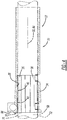
FIG. 1 is a top perspective view of a steering column assembly incorporating engineered tape between a box rocker inner diameter and a column jacket outer diameter and constructed in accordance to the present disclosure, the column jacket located in a first position relative to the box rocker; -
FIG. 2 is a bottom perspective view of the steering column assembly ofFIG. 1 ; -
FIG. 3 is a perspective view of the steering column assembly ofFIG. 1 and shown with the column jacket moved in a second position relative to the box rocker; -
FIG. 4 is a partial cross-sectional view of the steering column assembly taken along lines 4-4 ofFIG. 3 ; -
FIG. 5 is a perspective view of the box rocker ofFIG. 1 and shown without the engineered tape; -
FIG. 6 is a perspective view of the box rocker ofFIG. 1 and shown with the engineered tape positioned in a first location according to one example of the present disclosure; -
FIG. 7 is a front perspective view of the engineered tape shown disposed on the box rocker ofFIG. 1 ; -
FIG. 8 is a partial cross-sectional view of the steering column assembly taken along lines 8-8 ofFIG. 3 ; -
FIG. 9 is an end view of a box rocker incorporating engineered tape positioned at additional locations according to various implementations of the present disclosure; -
FIG. 10 is a cross-sectional view of a box rocker, column jacket and metal sleeve or rigid plastic sleeve according to Prior Art; and -
FIG. 11 is a cross-sectional view of a box rocker, column jacket and engineered tape according to one example of the present disclosure. - With initial reference to
FIGS. 1 and2 , a perspective view of a steering column assembly constructed in accordance to the present teachings is shown and generally identified atreference numeral 10. Thesteering column assembly 10 generally includes abox rocker 12 having abracket assembly 13, anelectric motor assembly 14, acolumn jacket 16, abiasing mount assembly 18 and engineeredtape 20, which can comprise any suitable tape that provides satisfactory compression and wear characteristics (see further explanation below). Thebracket assembly 13 includes afirst bracket 13a and asecond bracket 13b. Theelectric motor assembly 14 includes a firstelectric motor 14a and a secondelectric motor 14b. The firstelectric motor 14a is coupled with a first worm of a first worm gear, wherein the first worm meshes a first worm wheel. The first worm wheel comprises a first bore with a first outer thread. A first spindle engages into the thread of the first bore, wherein the first spindle is coupled with a height adjustment mechanism to adjust thecolumn jacket 16 and thebox rocker 12 relative to thefirst bracket 13a. The secondelectric motor 14b is coupled with a second worm of a second worm gear, wherein the second worm meshes a second worm wheel. The second worm wheel comprises a second bore with a second outer thread. A second spindle engages into the thread of the second bore, wherein the second spindle is coupled with a length adjustment mechanism to adjust thecolumn jacket 16 relative to thebox rocker 12 along a longitudinalcolumn jacket axis 60. - The biasing
mount assembly 18 includes a pair of biasingmounts box rocker 12 and configured to urge thecolumn jacket 16 toward the engineeredtape 20 disposed on an opposite side of thebox rocker 12 as will be described in greater detail herein. The first andsecond brackets steering column assembly 10 relative to a vehicle. The first and secondelectric motors box rocker 12 andcolumn jacket 16 relative to a driver in a vehicle. It will be appreciated that the configuration of themotor assembly 14 andbracket assembly 13 is merely exemplary and other arrangements may be used for thesteering column assembly 10 within the scope of the present disclosure. - The
column jacket 16 is configured to telescope relative to thebox rocker 12 between the positions shown inFIG. 1 andFIG. 3 . As will be described in greater detail herein, the engineeredtape 20 is positioned between thebox rocker 12 and thecolumn jacket 16 to mitigate wear between thebox rocker 12 andcolumn jacket 16 and to provide other benefits as explained below. - With particular reference to
FIGS. 1 ,5 and9 , thebox rocker 12 will be further described. Thebox rocker 12 comprises arocker body 24 that includes a mountingbore 28 and generally defines a box rocker bore 30. The mounting bore 28 is configured to receive a mountingaxle 31 that couples with thebracket 13a to facilitate mounting of thebox rocker 12 to the vehicle. The box rocker bore 30 extends along abore axis 32 and is generally defined by afluted section 34 provided by a plurality of radially stepped insurfaces 36 and a plurality of radially stepped out surfaces 38. The plurality of stepped insurfaces 36 collectively provide a box rockerinner surface 40 along a box rockerinner diameter 42. The box rockerinner surface 40 slidably receives thecolumn jacket 16 as will be understood below. While five stepped insurfaces 36 and four stepped outsurfaces 38 are shown, it is appreciated that additional or fewer stepped in and outsurfaces surfaces inner surface 40 may take on a continuous circumferential surface without any fluting. - With reference now to
FIG. 2 , the biasingmount assembly 18 will be described in greater detail. Both of the biasingmount assemblies pad member screw members respective pads mount assemblies 18 locate into arc shapedscrew holes column jacket 16. Thescrews mount assemblies column jacket 16. - With particular reference now to
FIGS. 1-4 , thecolumn jacket 16 will be further described. Thecolumn jacket 16 generally includes aninner jacket tube 58 and a steeringshaft 59. Thecolumn jacket 16 extends along a longitudinalcolumn jacket axis 60. The steeringshaft 59 includes a steeringspindle 62 having a steeringwheel mounting feature 64 arranged on a distal end thereof. The steeringwheel mounting feature 64 includes threads and a splined portion however other arrangements are contemplated. - The
inner jacket tube 58 includes a column jacketouter diameter 70 having anouter surface 72 that opposes the box rockerinner surface 40. In some instances thebox rocker 12 receives the inner jacket (tube) 58. Theouter surface 72 can have a generally cylindrical profile however other geometries are contemplated for receipt into the box rocker bore 30. For example, thebox rocker 12 andcolumn jacket 16 can define other complementary shapes such as, but not limited to, hexagonal within the scope of this disclosure. In some example shown inFIGS 1-4 and6 , the engineeredtape 20 is disposed partially onto theinner surface 40. In the example shown, the engineeredtape 20 is disposed onto some of the radially stepped insurfaces 36. In this example, the engineeredtape 20 is at least partially adhered to radially stepped insurfaces 36 located generally around an upper circumference of the box rocker bore 30. As used herein "upper"' circumference is used as a reference to an orientation thesteering column assembly 10 has while assembled onto a vehicle. - During translation of the
column jacket 16 within the box rocker bore 30, theouter surface 72 of theinner jacket tube 58 of thecolumn jacket 16 is caused to slidably ride along the engineeredtape 20 on theinner surface 40 of thebox rocker 12. Because the engineeredtape 20 is positioned between theouter surface 72 and theinner surface 40, direct sliding contact between theouter surface 72 of thecolumn jacket 16 and theinner surface 40 of thebox rocker 12 is significantly reduced. The engineeredtape 20 can significantly reduce wear between thecolumn jacket 16 and thebox rocker 12. Further, the arrangement can reduce shavings, debris and other particles that can drop or otherwise discharge onto the mating surfaces of thecolumn jacket 16 andbox rocker 12. Such an arrangement is particularly advantageous when dissimilar materials are used for thecolumn jacket 16 andbox rocker 12. For example, the implementation of engineeredtape 20 reduces wear patterns seen between steel column jackets and magnesium box rockers. - In one advantage of the instant disclosure, the engineered
tape 20 is highly flexible and compressible. The engineeredtape 20 can compress, flow and adjust into rigid part surface irregularities such as, but not limited to, roughness, grooves, pockets, pin-holes surface waves and tool marks. In this regard, the engineeredtape 20 can provide better axis alignment, control and cooperation between moving parts and improve stiffness between thecolumn jacket 16 andbox rocker 12. A comparison is shown inFIGS. 10 and 11. FIG. 10 is a Prior Art example of abox rocker 112 and acolumn jacket 116 having a rigid member such as a plastic ormetal sleeve 120 arranged therebetween according to one example of Prior Art. In the Prior Art arrangement shown inFIG. 10 , gaps and/orvoids 122 can exist between thebox rocker 112,column jacket 116 andsleeve 120. In comparison, turning toFIG. 11 , thebox rocker 12,column jacket 16 and engineeredtape 20 substantially eliminates such gaps. Explained further, because the engineered tape compresses, a more intimate contact results between theouter surface 72 of thecolumn jacket 16 and theinner surface 40 of thebox rocker 12. As a result, voids gaps and surface irregularities are filled. Moreover, stiffness and axis alignment of theoverall steering column 10 is improved. - With particular reference now to
FIGS. 5-8 , the engineeredtape 20 will be further described. As is known,engineered tape 20 is flexible, compressible and easily cut to a desired shape. It will be appreciated that the term "tape" is used herein to encompass film or other materials having similar characteristics with respect to the engineeredtape 20. In this regard, the engineeredtape 20 does not have pre-defined rigid forms, highly defined shapes, or high tolerance geometries. In this regard, theengineering tape 20 can match rigid mating radii, slots, bores, posts, grooves, or other surfaces of a box rocker. Cost reductions and savings can be realized from the engineeredtape 20 as it is more easily assembled when cut from a roll or sheet and placed quickly onto a surface (such as the inner surface 40). The engineeredtape 20 does not have to closely match rigid part geometries, thus reducing highly machined and tolerance part geometry mismatches. The engineeredtape 20 can overlap features, cover a desired footprint, be manipulated into positions and adjusted quickly to assemble and perform acceptably. The engineeredtape 20 can be quickly cut to provide a wide variety of footprints as compared to rigid defined shape metal, hard resin pre-molded or other rigid machined, bent, turned or hard formed components. - In the particular example shown in
FIGS. 6 and7 , the engineeredtape 20 has been cut generally into a shape having afootprint 78 suitable to place onto anarea 80 of theinner surface 40. Thearea 80 can be defined as any area where wear protection is desired. The engineeredtape 20 also hasslots 90 cut thereon that generally createtabs 92 that can adhere to aface 94 of thebox rocker 12. It will be appreciated that the engineeredtape 20 does not necessarily need to be adhered to theface 94. In some examples the engineeredtape 20 can be adhered to theface 94 as a visual indicator that installation of the engineeredtape 20 has been completed. The engineeredtape 20 can be adhered to the radially stepped insurfaces 36 around theinner surface 40. While not required, in some examples, the engineeredtape 20 can additionally adhere to the radially stepped out surfaces 38. In other examples, some or all of the engineeredtape 20 can alternatively be adhered to theouter surface 72 of thecolumn jacket 16. - Again, it is appreciated that the engineered
tape 20 can be cut into any size suitable for a given application. It is further appreciated that multiple sections of engineeredtape inner diameter 42 onto theinner surface 40. It may be desirable to use some or all sections of engineeredtape tape - The engineered
tape 20 can comprise any suitable tape that provides satisfactory compression and wear characteristics. Exemplary engineered tapes include, but are not limited to, McMaster Carr Tape 2208T72 marketed by Integument Technologies, Inc. and having product number P550W-A4-36. The McMaster Carr tape includes an oxy-fluoropolymer of polytetrafluoroethylene modified to incorporate hydroxyl groups with an acrylic or silicone pressure sensitive adhesive. Other suitable tapes include tape marketed by Shenzhen Western Hemisphere Technology Co., Ltd., Part No. WH-013. The tape may be formed of glass fiber or Teflon®. In some non-limiting examples, the tape can have a thickness between 0.05 mm and 0.5 mm, preferably between 0.1 mm and 0.2 mm and especially preferred between 0.12 mm and 0.18 mm. The tape can further have surface conformance and tape compression between 0.01 to 0.05 mm. In some examples the tape can compress generally between 20% and 25% and in some instances between approximately 5% and 35%.
Claims (20)
- A steering column assembly (10) for a motor vehicle, the steering column assembly (10) comprising:a box rocker (12) having a rocker body including a box rocker inner surface (40) that defines a box rocker bore (30), the box rocker (12) configured to be fixed relative to the motor vehicle in an assembled position;a column jacket (16) configured to be slidably received into the box rocker bore (30), the column jacket (16) having a column jacket outer diameter (70) including an outer surface (72) that opposes the box rocker inner surface (40); characterized in thata first section of tape (20) disposed between the box rocker (12) inner surface (40) and the column jacket outer surface (72).
- The steering column assembly of claim 1 wherein the first section of tape (20) is at least partially adhered to the box rocker (12) inner surface (40).
- The steering column assembly of claim 2 wherein the first section of tape (20) is further adhered to a face surface of the box rocker body.
- The steering column assembly of claim 2 wherein the first section of tape (20) is positioned generally around an upper circumference of the box rocker bore (30).
- The steering column assembly of claim 4 wherein the first section of tape (20) is configured to compress between 20% and 25%.
- The steering column assembly of claim 1 wherein the box rocker (12) includes a fluted section provided by a plurality of radially stepped in surfaces (36) and a plurality of radially stepped out surfaces (38), the plurality of stepped in surfaces (36) collectively providing the box rocker inner (40) surface.
- The steering column assembly of claim 6 wherein the first section of tape(20) is positioned onto at least two adjacent radially stepped in surfaces (36) of the plurality of radially stepped in surfaces (36).
- The steering column assembly of claim 1 wherein the inner surface (40) of the box rocker (12) and the outer surface (72) of the column jacket (16) are substantially concentric.
- The steering column assembly of claim 1 wherein the column jacket (16) is configured to translate within the box rocker bore (30), wherein during translation, the outer surface (72) of the column jacket (16) is caused to slidably ride along the first section of tape (20) disposed on the inner surface (40) of the box rocker (12).
- The steering column assembly of claim 1 wherein the column jacket (16) is formed of steel and the box rocker (12) is formed of magnesium.
- The steering column assembly of claim 4 wherein the first section of tape (20) has a thickness of between 0.05 mm and 0.5 mm.
- The steering column assembly of claim 11 wherein the first section of tape (20) has a thickness of between 0.1 mm and 0.2 mm.
- The steering column assembly of claim 12 wherein the first section of tape (20) has a thickness of between 0.12 mm and 0.18 mm.
- The steering column assembly of claim 4 wherein the first section of tape (20) has one of acrylic and silicone pressure sensitive adhesive.
- The steering column assembly of claim 4, further comprising a second section of tape (20), distinct from the first section of tape (20) and disposed between the box rocker inner surface (40) and the column jacket outer surface (72).
- The steering column assembly of claim 15 wherein the first and second sections of tape (20) are of different geometries having distinct footprints.
- The steering column assembly of claim 15, further comprising a third section of tape (20), distinct from the first and second sections of tape (20) and disposed between the box rocker inner surface (40) and the column jacket outer surface (72).
- A method of assembling a column jacket (16) relative to a box rocker (12) of a steering column assembly (10) for a motor vehicle, the method comprising:identifying a mating contact surface of the box rocker (12);disposing a first section of tape (20) onto an inner surface (40) of the box rocker (12) at the mating contact surface; andslidably inserting the column jacket (16) into a bore defined by the inner surface (40) of the box rocker (12) wherein an outer surface (72) of the column jacket slidably advances along the first section of tape (20) mitigating surface to surface contact between the column jacket (16) and the box rocker (12).
- The method of claim 18 wherein disposing the first section of tape (20) comprises:
cutting the first section of tape (20) from one of a roll and sheet, the first section of tape (20) corresponding to a desired area of the inner surface (40) of the box rocker (12). - The method of claim 19 wherein disposing the first section of tape (20) further comprises:cutting slots into the tape (20) to create tabs; andadhering the tabs to a face of the box rocker (12).
Applications Claiming Priority (2)
| Application Number | Priority Date | Filing Date | Title |
|---|---|---|---|
| US15/677,392 US10458462B2 (en) | 2017-08-15 | 2017-08-15 | Steering column engineered tape |
| PCT/EP2018/071803 WO2019034566A1 (en) | 2017-08-15 | 2018-08-10 | Steering column engineered tape |
Publications (2)
| Publication Number | Publication Date |
|---|---|
| EP3668775A1 EP3668775A1 (en) | 2020-06-24 |
| EP3668775B1 true EP3668775B1 (en) | 2021-07-28 |
Family
ID=63244587
Family Applications (1)
| Application Number | Title | Priority Date | Filing Date |
|---|---|---|---|
| EP18755778.0A Active EP3668775B1 (en) | 2017-08-15 | 2018-08-10 | Steering column engineered tape |
Country Status (4)
| Country | Link |
|---|---|
| US (1) | US10458462B2 (en) |
| EP (1) | EP3668775B1 (en) |
| CN (1) | CN111032479B (en) |
| WO (1) | WO2019034566A1 (en) |
Families Citing this family (2)
| Publication number | Priority date | Publication date | Assignee | Title |
|---|---|---|---|---|
| US11396319B2 (en) * | 2020-11-23 | 2022-07-26 | Steering Solutions Ip Holding Corporation | Steering column jacket stiffening sleeve |
| DE102021003660A1 (en) * | 2021-07-09 | 2023-01-12 | Schaeffler Technologies AG & Co. KG | Adjusting device for steering columns of vehicles |
Family Cites Families (13)
| Publication number | Priority date | Publication date | Assignee | Title |
|---|---|---|---|---|
| JPH1053144A (en) | 1996-08-09 | 1998-02-24 | Toyota Motor Corp | Telescopic steering device |
| FR2784343B1 (en) * | 1998-10-07 | 2001-01-05 | Ecia Equip Composants Ind Auto | POSITION ADJUSTABLE STEERING COLUMN ASSEMBLY, FOR EXAMPLE FOR A MOTOR VEHICLE |
| JP2007032324A (en) | 2005-07-25 | 2007-02-08 | Toyota Motor Corp | Control device for internal combustion engine |
| DE102008005256B4 (en) | 2008-01-18 | 2009-10-22 | Thyssenkrupp Presta Ag | Steering column with plastic sliding sleeve |
| US7874588B2 (en) | 2008-02-13 | 2011-01-25 | Nexteer (Beijing) Technology Co., Ltd. | Telescopically adjustable steering column assembly |
| DE102008049747A1 (en) | 2008-09-30 | 2010-04-01 | Saint-Gobain Performance Plastics Pampus Gmbh | Vibration-damping plain bearing composite material and plain bearing bush and plain bearing arrangement |
| CN201494492U (en) * | 2009-09-10 | 2010-06-02 | 浙江天岳汽车电器有限公司 | Straight-line bearing type steering telescopic shaft assembly |
| CN102792036A (en) | 2009-12-18 | 2012-11-21 | 圣戈班性能塑料帕姆普斯有限公司 | Systems, methods and apparatus for tolerance rings with functional layers |
| KR101624234B1 (en) * | 2010-09-29 | 2016-05-25 | 현대자동차주식회사 | Combining structure for Steering Column Mounting with Vibration Isolation |
| JP5765628B2 (en) | 2011-09-26 | 2015-08-19 | アイシン精機株式会社 | Vehicle steering device |
| US20130133461A1 (en) * | 2011-11-30 | 2013-05-30 | Nexteer (Beijing) Technology Co., Ltd. | Energy absorbing steering column assembly |
| DE102012104644B3 (en) | 2012-05-30 | 2013-08-08 | Thyssenkrupp Presta Aktiengesellschaft | Steering column for a motor vehicle |
| DE102013103328A1 (en) | 2013-04-03 | 2014-10-09 | Thyssenkrupp Presta Aktiengesellschaft | Method for producing a steering spindle bearing unit |
-
2017
- 2017-08-15 US US15/677,392 patent/US10458462B2/en active Active
-
2018
- 2018-08-10 CN CN201880052613.6A patent/CN111032479B/en active Active
- 2018-08-10 EP EP18755778.0A patent/EP3668775B1/en active Active
- 2018-08-10 WO PCT/EP2018/071803 patent/WO2019034566A1/en not_active Ceased
Also Published As
| Publication number | Publication date |
|---|---|
| WO2019034566A1 (en) | 2019-02-21 |
| US20190055981A1 (en) | 2019-02-21 |
| CN111032479B (en) | 2022-05-06 |
| EP3668775A1 (en) | 2020-06-24 |
| CN111032479A (en) | 2020-04-17 |
| US10458462B2 (en) | 2019-10-29 |
Similar Documents
| Publication | Publication Date | Title |
|---|---|---|
| CN100439148C (en) | Vehicle power seat slide device | |
| CN100486849C (en) | Apparatus for automatically compensating for clearance of support yoke in rack-and-pinion steering system | |
| US8887590B2 (en) | Automatic clearance compensation device for support yoke of rack-pinion type steering apparatus | |
| US20170015345A1 (en) | Steering column for a motor vehicle | |
| US10458462B2 (en) | Steering column engineered tape | |
| CN107438550B (en) | Steering column with bearing block capable of being flexibly assembled | |
| US9815489B2 (en) | Device for pressing a gear rack against a pinion | |
| CN107428361B (en) | Steering column with adjustable pivot support | |
| EP1396415A3 (en) | Steering column with tubular structure | |
| CN103085856A (en) | Yoke assembly for power steering rack and pinion gear set | |
| KR100861544B1 (en) | Support yoke automatic play compensation for rack pinion type steering system | |
| EP3466752B1 (en) | Gearbox assembly and headrest driver comprising same | |
| WO2006071448A3 (en) | Guide wheel having integrated bearing mount | |
| CN107597892B (en) | Shaping disc assembly of pipe fitting port shaping machine | |
| EP0308155A3 (en) | Cutting and the like tools | |
| KR20210038424A (en) | Mounting system for grinding machines | |
| KR20150051558A (en) | rack bar support device of steering gear for car | |
| US20180327018A1 (en) | Vertical position adjustment device for steering wheel | |
| JPH11222139A (en) | Vehicle steering system | |
| US20060278465A1 (en) | Steering system | |
| KR101734125B1 (en) | Clearance compensator of steering gear for car | |
| JP2013154709A (en) | Steering device for vehicle and rack guide mechanism | |
| US20070028711A1 (en) | Device for pressing a gear rack against a pinion meshing with the gear rack | |
| KR20170116835A (en) | Electronic Telescope Steering Column for Vehicle | |
| KR101786399B1 (en) | Device for supporting steering gear of vehicle |
Legal Events
| Date | Code | Title | Description |
|---|---|---|---|
| STAA | Information on the status of an ep patent application or granted ep patent |
Free format text: STATUS: UNKNOWN |
|
| STAA | Information on the status of an ep patent application or granted ep patent |
Free format text: STATUS: THE INTERNATIONAL PUBLICATION HAS BEEN MADE |
|
| PUAI | Public reference made under article 153(3) epc to a published international application that has entered the european phase |
Free format text: ORIGINAL CODE: 0009012 |
|
| STAA | Information on the status of an ep patent application or granted ep patent |
Free format text: STATUS: REQUEST FOR EXAMINATION WAS MADE |
|
| 17P | Request for examination filed |
Effective date: 20200316 |
|
| AK | Designated contracting states |
Kind code of ref document: A1 Designated state(s): AL AT BE BG CH CY CZ DE DK EE ES FI FR GB GR HR HU IE IS IT LI LT LU LV MC MK MT NL NO PL PT RO RS SE SI SK SM TR |
|
| AX | Request for extension of the european patent |
Extension state: BA ME |
|
| DAV | Request for validation of the european patent (deleted) | ||
| DAX | Request for extension of the european patent (deleted) | ||
| RIN1 | Information on inventor provided before grant (corrected) |
Inventor name: PICHONNAT, CHRISTIAN Inventor name: WELCH, BRYCE Inventor name: MCBRIDE, STEPHEN |
|
| GRAP | Despatch of communication of intention to grant a patent |
Free format text: ORIGINAL CODE: EPIDOSNIGR1 |
|
| STAA | Information on the status of an ep patent application or granted ep patent |
Free format text: STATUS: GRANT OF PATENT IS INTENDED |
|
| INTG | Intention to grant announced |
Effective date: 20210310 |
|
| GRAS | Grant fee paid |
Free format text: ORIGINAL CODE: EPIDOSNIGR3 |
|
| GRAA | (expected) grant |
Free format text: ORIGINAL CODE: 0009210 |
|
| STAA | Information on the status of an ep patent application or granted ep patent |
Free format text: STATUS: THE PATENT HAS BEEN GRANTED |
|
| AK | Designated contracting states |
Kind code of ref document: B1 Designated state(s): AL AT BE BG CH CY CZ DE DK EE ES FI FR GB GR HR HU IE IS IT LI LT LU LV MC MK MT NL NO PL PT RO RS SE SI SK SM TR |
|
| REG | Reference to a national code |
Ref country code: GB Ref legal event code: FG4D |
|
| REG | Reference to a national code |
Ref country code: CH Ref legal event code: EP |
|
| REG | Reference to a national code |
Ref country code: AT Ref legal event code: REF Ref document number: 1414508 Country of ref document: AT Kind code of ref document: T Effective date: 20210815 |
|
| REG | Reference to a national code |
Ref country code: IE Ref legal event code: FG4D |
|
| REG | Reference to a national code |
Ref country code: DE Ref legal event code: R096 Ref document number: 602018020879 Country of ref document: DE |
|
| REG | Reference to a national code |
Ref country code: LT Ref legal event code: MG9D |
|
| REG | Reference to a national code |
Ref country code: NL Ref legal event code: MP Effective date: 20210728 |
|
| REG | Reference to a national code |
Ref country code: AT Ref legal event code: MK05 Ref document number: 1414508 Country of ref document: AT Kind code of ref document: T Effective date: 20210728 |
|
| PG25 | Lapsed in a contracting state [announced via postgrant information from national office to epo] |
Ref country code: RS Free format text: LAPSE BECAUSE OF FAILURE TO SUBMIT A TRANSLATION OF THE DESCRIPTION OR TO PAY THE FEE WITHIN THE PRESCRIBED TIME-LIMIT Effective date: 20210728 Ref country code: SE Free format text: LAPSE BECAUSE OF FAILURE TO SUBMIT A TRANSLATION OF THE DESCRIPTION OR TO PAY THE FEE WITHIN THE PRESCRIBED TIME-LIMIT Effective date: 20210728 Ref country code: HR Free format text: LAPSE BECAUSE OF FAILURE TO SUBMIT A TRANSLATION OF THE DESCRIPTION OR TO PAY THE FEE WITHIN THE PRESCRIBED TIME-LIMIT Effective date: 20210728 Ref country code: ES Free format text: LAPSE BECAUSE OF FAILURE TO SUBMIT A TRANSLATION OF THE DESCRIPTION OR TO PAY THE FEE WITHIN THE PRESCRIBED TIME-LIMIT Effective date: 20210728 Ref country code: FI Free format text: LAPSE BECAUSE OF FAILURE TO SUBMIT A TRANSLATION OF THE DESCRIPTION OR TO PAY THE FEE WITHIN THE PRESCRIBED TIME-LIMIT Effective date: 20210728 Ref country code: LT Free format text: LAPSE BECAUSE OF FAILURE TO SUBMIT A TRANSLATION OF THE DESCRIPTION OR TO PAY THE FEE WITHIN THE PRESCRIBED TIME-LIMIT Effective date: 20210728 Ref country code: BG Free format text: LAPSE BECAUSE OF FAILURE TO SUBMIT A TRANSLATION OF THE DESCRIPTION OR TO PAY THE FEE WITHIN THE PRESCRIBED TIME-LIMIT Effective date: 20211028 Ref country code: AT Free format text: LAPSE BECAUSE OF FAILURE TO SUBMIT A TRANSLATION OF THE DESCRIPTION OR TO PAY THE FEE WITHIN THE PRESCRIBED TIME-LIMIT Effective date: 20210728 Ref country code: NO Free format text: LAPSE BECAUSE OF FAILURE TO SUBMIT A TRANSLATION OF THE DESCRIPTION OR TO PAY THE FEE WITHIN THE PRESCRIBED TIME-LIMIT Effective date: 20211028 Ref country code: PT Free format text: LAPSE BECAUSE OF FAILURE TO SUBMIT A TRANSLATION OF THE DESCRIPTION OR TO PAY THE FEE WITHIN THE PRESCRIBED TIME-LIMIT Effective date: 20211129 Ref country code: NL Free format text: LAPSE BECAUSE OF FAILURE TO SUBMIT A TRANSLATION OF THE DESCRIPTION OR TO PAY THE FEE WITHIN THE PRESCRIBED TIME-LIMIT Effective date: 20210728 |
|
| PG25 | Lapsed in a contracting state [announced via postgrant information from national office to epo] |
Ref country code: PL Free format text: LAPSE BECAUSE OF FAILURE TO SUBMIT A TRANSLATION OF THE DESCRIPTION OR TO PAY THE FEE WITHIN THE PRESCRIBED TIME-LIMIT Effective date: 20210728 Ref country code: LV Free format text: LAPSE BECAUSE OF FAILURE TO SUBMIT A TRANSLATION OF THE DESCRIPTION OR TO PAY THE FEE WITHIN THE PRESCRIBED TIME-LIMIT Effective date: 20210728 Ref country code: GR Free format text: LAPSE BECAUSE OF FAILURE TO SUBMIT A TRANSLATION OF THE DESCRIPTION OR TO PAY THE FEE WITHIN THE PRESCRIBED TIME-LIMIT Effective date: 20211029 |
|
| REG | Reference to a national code |
Ref country code: CH Ref legal event code: PL |
|
| REG | Reference to a national code |
Ref country code: BE Ref legal event code: MM Effective date: 20210831 |
|
| PG25 | Lapsed in a contracting state [announced via postgrant information from national office to epo] |
Ref country code: LI Free format text: LAPSE BECAUSE OF NON-PAYMENT OF DUE FEES Effective date: 20210831 Ref country code: DK Free format text: LAPSE BECAUSE OF FAILURE TO SUBMIT A TRANSLATION OF THE DESCRIPTION OR TO PAY THE FEE WITHIN THE PRESCRIBED TIME-LIMIT Effective date: 20210728 Ref country code: CH Free format text: LAPSE BECAUSE OF NON-PAYMENT OF DUE FEES Effective date: 20210831 |
|
| REG | Reference to a national code |
Ref country code: DE Ref legal event code: R097 Ref document number: 602018020879 Country of ref document: DE |
|
| PG25 | Lapsed in a contracting state [announced via postgrant information from national office to epo] |
Ref country code: SM Free format text: LAPSE BECAUSE OF FAILURE TO SUBMIT A TRANSLATION OF THE DESCRIPTION OR TO PAY THE FEE WITHIN THE PRESCRIBED TIME-LIMIT Effective date: 20210728 Ref country code: SK Free format text: LAPSE BECAUSE OF FAILURE TO SUBMIT A TRANSLATION OF THE DESCRIPTION OR TO PAY THE FEE WITHIN THE PRESCRIBED TIME-LIMIT Effective date: 20210728 Ref country code: RO Free format text: LAPSE BECAUSE OF FAILURE TO SUBMIT A TRANSLATION OF THE DESCRIPTION OR TO PAY THE FEE WITHIN THE PRESCRIBED TIME-LIMIT Effective date: 20210728 Ref country code: MC Free format text: LAPSE BECAUSE OF FAILURE TO SUBMIT A TRANSLATION OF THE DESCRIPTION OR TO PAY THE FEE WITHIN THE PRESCRIBED TIME-LIMIT Effective date: 20210728 Ref country code: LU Free format text: LAPSE BECAUSE OF NON-PAYMENT OF DUE FEES Effective date: 20210810 Ref country code: EE Free format text: LAPSE BECAUSE OF FAILURE TO SUBMIT A TRANSLATION OF THE DESCRIPTION OR TO PAY THE FEE WITHIN THE PRESCRIBED TIME-LIMIT Effective date: 20210728 Ref country code: CZ Free format text: LAPSE BECAUSE OF FAILURE TO SUBMIT A TRANSLATION OF THE DESCRIPTION OR TO PAY THE FEE WITHIN THE PRESCRIBED TIME-LIMIT Effective date: 20210728 Ref country code: AL Free format text: LAPSE BECAUSE OF FAILURE TO SUBMIT A TRANSLATION OF THE DESCRIPTION OR TO PAY THE FEE WITHIN THE PRESCRIBED TIME-LIMIT Effective date: 20210728 |
|
| PLBE | No opposition filed within time limit |
Free format text: ORIGINAL CODE: 0009261 |
|
| STAA | Information on the status of an ep patent application or granted ep patent |
Free format text: STATUS: NO OPPOSITION FILED WITHIN TIME LIMIT |
|
| 26N | No opposition filed |
Effective date: 20220429 |
|
| PG25 | Lapsed in a contracting state [announced via postgrant information from national office to epo] |
Ref country code: IT Free format text: LAPSE BECAUSE OF FAILURE TO SUBMIT A TRANSLATION OF THE DESCRIPTION OR TO PAY THE FEE WITHIN THE PRESCRIBED TIME-LIMIT Effective date: 20210728 Ref country code: IE Free format text: LAPSE BECAUSE OF NON-PAYMENT OF DUE FEES Effective date: 20210810 Ref country code: BE Free format text: LAPSE BECAUSE OF NON-PAYMENT OF DUE FEES Effective date: 20210831 |
|
| REG | Reference to a national code |
Ref country code: DE Ref legal event code: R084 Ref document number: 602018020879 Country of ref document: DE |
|
| PG25 | Lapsed in a contracting state [announced via postgrant information from national office to epo] |
Ref country code: CY Free format text: LAPSE BECAUSE OF FAILURE TO SUBMIT A TRANSLATION OF THE DESCRIPTION OR TO PAY THE FEE WITHIN THE PRESCRIBED TIME-LIMIT Effective date: 20210728 |
|
| PG25 | Lapsed in a contracting state [announced via postgrant information from national office to epo] |
Ref country code: HU Free format text: LAPSE BECAUSE OF FAILURE TO SUBMIT A TRANSLATION OF THE DESCRIPTION OR TO PAY THE FEE WITHIN THE PRESCRIBED TIME-LIMIT; INVALID AB INITIO Effective date: 20180810 |
|
| PG25 | Lapsed in a contracting state [announced via postgrant information from national office to epo] |
Ref country code: MK Free format text: LAPSE BECAUSE OF FAILURE TO SUBMIT A TRANSLATION OF THE DESCRIPTION OR TO PAY THE FEE WITHIN THE PRESCRIBED TIME-LIMIT Effective date: 20210728 |
|
| PG25 | Lapsed in a contracting state [announced via postgrant information from national office to epo] |
Ref country code: MT Free format text: LAPSE BECAUSE OF FAILURE TO SUBMIT A TRANSLATION OF THE DESCRIPTION OR TO PAY THE FEE WITHIN THE PRESCRIBED TIME-LIMIT Effective date: 20210728 |
|
| PGFP | Annual fee paid to national office [announced via postgrant information from national office to epo] |
Ref country code: DE Payment date: 20250820 Year of fee payment: 8 |
|
| PGFP | Annual fee paid to national office [announced via postgrant information from national office to epo] |
Ref country code: GB Payment date: 20250820 Year of fee payment: 8 |
|
| PGFP | Annual fee paid to national office [announced via postgrant information from national office to epo] |
Ref country code: FR Payment date: 20250828 Year of fee payment: 8 |
|
| PG25 | Lapsed in a contracting state [announced via postgrant information from national office to epo] |
Ref country code: TR Free format text: LAPSE BECAUSE OF FAILURE TO SUBMIT A TRANSLATION OF THE DESCRIPTION OR TO PAY THE FEE WITHIN THE PRESCRIBED TIME-LIMIT Effective date: 20210728 |