EP3668741B1 - Common exhaust passage for transport refrigeration unit and vehicle - Google Patents
Common exhaust passage for transport refrigeration unit and vehicle Download PDFInfo
- Publication number
- EP3668741B1 EP3668741B1 EP17783990.9A EP17783990A EP3668741B1 EP 3668741 B1 EP3668741 B1 EP 3668741B1 EP 17783990 A EP17783990 A EP 17783990A EP 3668741 B1 EP3668741 B1 EP 3668741B1
- Authority
- EP
- European Patent Office
- Prior art keywords
- engine
- exhaust passage
- exhaust
- refrigeration unit
- transport
- Prior art date
- Legal status (The legal status is an assumption and is not a legal conclusion. Google has not performed a legal analysis and makes no representation as to the accuracy of the status listed.)
- Active
Links
- 238000005057 refrigeration Methods 0.000 title claims description 82
- 230000003197 catalytic effect Effects 0.000 claims description 24
- 238000000034 method Methods 0.000 claims description 16
- 230000001143 conditioned effect Effects 0.000 claims description 6
- 238000011144 upstream manufacturing Methods 0.000 claims description 6
- 239000003507 refrigerant Substances 0.000 description 38
- 239000003570 air Substances 0.000 description 22
- 239000000446 fuel Substances 0.000 description 21
- 239000002828 fuel tank Substances 0.000 description 14
- 238000010521 absorption reaction Methods 0.000 description 8
- 230000006835 compression Effects 0.000 description 8
- 238000007906 compression Methods 0.000 description 8
- VNWKTOKETHGBQD-UHFFFAOYSA-N methane Chemical compound C VNWKTOKETHGBQD-UHFFFAOYSA-N 0.000 description 8
- 238000004590 computer program Methods 0.000 description 5
- CURLTUGMZLYLDI-UHFFFAOYSA-N Carbon dioxide Chemical compound O=C=O CURLTUGMZLYLDI-UHFFFAOYSA-N 0.000 description 4
- 239000007789 gas Substances 0.000 description 4
- 239000003345 natural gas Substances 0.000 description 4
- 238000012545 processing Methods 0.000 description 4
- 238000001816 cooling Methods 0.000 description 3
- 230000008569 process Effects 0.000 description 3
- 241000251468 Actinopterygii Species 0.000 description 2
- 235000010627 Phaseolus vulgaris Nutrition 0.000 description 2
- 244000046052 Phaseolus vulgaris Species 0.000 description 2
- 230000005540 biological transmission Effects 0.000 description 2
- 239000006227 byproduct Substances 0.000 description 2
- 229910002092 carbon dioxide Inorganic materials 0.000 description 2
- 239000001569 carbon dioxide Substances 0.000 description 2
- 235000013339 cereals Nutrition 0.000 description 2
- 238000002485 combustion reaction Methods 0.000 description 2
- 235000013365 dairy product Nutrition 0.000 description 2
- 239000003814 drug Substances 0.000 description 2
- 235000013399 edible fruits Nutrition 0.000 description 2
- 230000000694 effects Effects 0.000 description 2
- 235000013601 eggs Nutrition 0.000 description 2
- 230000007613 environmental effect Effects 0.000 description 2
- 239000003502 gasoline Substances 0.000 description 2
- 239000003949 liquefied natural gas Substances 0.000 description 2
- 235000013372 meat Nutrition 0.000 description 2
- 230000007246 mechanism Effects 0.000 description 2
- 239000000203 mixture Substances 0.000 description 2
- 235000014571 nuts Nutrition 0.000 description 2
- 230000003287 optical effect Effects 0.000 description 2
- 244000144977 poultry Species 0.000 description 2
- 230000001360 synchronised effect Effects 0.000 description 2
- 235000013311 vegetables Nutrition 0.000 description 2
- IJGRMHOSHXDMSA-UHFFFAOYSA-N Atomic nitrogen Chemical compound N#N IJGRMHOSHXDMSA-UHFFFAOYSA-N 0.000 description 1
- VGGSQFUCUMXWEO-UHFFFAOYSA-N Ethene Chemical compound C=C VGGSQFUCUMXWEO-UHFFFAOYSA-N 0.000 description 1
- 239000005977 Ethylene Substances 0.000 description 1
- CBENFWSGALASAD-UHFFFAOYSA-N Ozone Chemical compound [O-][O+]=O CBENFWSGALASAD-UHFFFAOYSA-N 0.000 description 1
- 239000012080 ambient air Substances 0.000 description 1
- 239000008280 blood Substances 0.000 description 1
- 210000004369 blood Anatomy 0.000 description 1
- 239000003054 catalyst Substances 0.000 description 1
- 238000004891 communication Methods 0.000 description 1
- 230000003750 conditioning effect Effects 0.000 description 1
- 230000008878 coupling Effects 0.000 description 1
- 238000010168 coupling process Methods 0.000 description 1
- 238000005859 coupling reaction Methods 0.000 description 1
- 238000010586 diagram Methods 0.000 description 1
- 238000009429 electrical wiring Methods 0.000 description 1
- 230000005670 electromagnetic radiation Effects 0.000 description 1
- 239000003344 environmental pollutant Substances 0.000 description 1
- 239000000835 fiber Substances 0.000 description 1
- 239000002803 fossil fuel Substances 0.000 description 1
- 230000006870 function Effects 0.000 description 1
- 239000007788 liquid Substances 0.000 description 1
- 239000000463 material Substances 0.000 description 1
- 238000005259 measurement Methods 0.000 description 1
- 238000012986 modification Methods 0.000 description 1
- 230000004048 modification Effects 0.000 description 1
- JCXJVPUVTGWSNB-UHFFFAOYSA-N nitrogen dioxide Inorganic materials O=[N]=O JCXJVPUVTGWSNB-UHFFFAOYSA-N 0.000 description 1
- 231100000719 pollutant Toxicity 0.000 description 1
- 238000010248 power generation Methods 0.000 description 1
Images


Classifications
-
- B—PERFORMING OPERATIONS; TRANSPORTING
- B60—VEHICLES IN GENERAL
- B60K—ARRANGEMENT OR MOUNTING OF PROPULSION UNITS OR OF TRANSMISSIONS IN VEHICLES; ARRANGEMENT OR MOUNTING OF PLURAL DIVERSE PRIME-MOVERS IN VEHICLES; AUXILIARY DRIVES FOR VEHICLES; INSTRUMENTATION OR DASHBOARDS FOR VEHICLES; ARRANGEMENTS IN CONNECTION WITH COOLING, AIR INTAKE, GAS EXHAUST OR FUEL SUPPLY OF PROPULSION UNITS IN VEHICLES
- B60K13/00—Arrangement in connection with combustion air intake or gas exhaust of propulsion units
- B60K13/04—Arrangement in connection with combustion air intake or gas exhaust of propulsion units concerning exhaust
-
- B—PERFORMING OPERATIONS; TRANSPORTING
- B60—VEHICLES IN GENERAL
- B60H—ARRANGEMENTS OF HEATING, COOLING, VENTILATING OR OTHER AIR-TREATING DEVICES SPECIALLY ADAPTED FOR PASSENGER OR GOODS SPACES OF VEHICLES
- B60H1/00—Heating, cooling or ventilating [HVAC] devices
- B60H1/00007—Combined heating, ventilating, or cooling devices
- B60H1/00014—Combined heating, ventilating, or cooling devices for load cargos on load transporting vehicles
-
- B—PERFORMING OPERATIONS; TRANSPORTING
- B60—VEHICLES IN GENERAL
- B60H—ARRANGEMENTS OF HEATING, COOLING, VENTILATING OR OTHER AIR-TREATING DEVICES SPECIALLY ADAPTED FOR PASSENGER OR GOODS SPACES OF VEHICLES
- B60H1/00—Heating, cooling or ventilating [HVAC] devices
- B60H1/00357—Air-conditioning arrangements specially adapted for particular vehicles
- B60H1/00364—Air-conditioning arrangements specially adapted for particular vehicles for caravans or trailers
-
- F—MECHANICAL ENGINEERING; LIGHTING; HEATING; WEAPONS; BLASTING
- F01—MACHINES OR ENGINES IN GENERAL; ENGINE PLANTS IN GENERAL; STEAM ENGINES
- F01N—GAS-FLOW SILENCERS OR EXHAUST APPARATUS FOR MACHINES OR ENGINES IN GENERAL; GAS-FLOW SILENCERS OR EXHAUST APPARATUS FOR INTERNAL COMBUSTION ENGINES
- F01N13/00—Exhaust or silencing apparatus characterised by constructional features ; Exhaust or silencing apparatus, or parts thereof, having pertinent characteristics not provided for in, or of interest apart from, groups F01N1/00 - F01N5/00, F01N9/00, F01N11/00
- F01N13/08—Other arrangements or adaptations of exhaust conduits
- F01N13/082—Other arrangements or adaptations of exhaust conduits of tailpipe, e.g. with means for mixing air with exhaust for exhaust cooling, dilution or evacuation
Definitions
- the subject matter disclosed herein generally relates to the field of transportation refrigeration systems, and more particularly to an apparatus and method of operating the exhaust systems of such transport refrigeration systems.
- cold chain distribution systems are used to transport and distribute cargo, or more specifically perishable goods and environmentally sensitive goods (herein referred to as perishable goods) that may be susceptible to temperature, humidity, and other environmental factors.
- Perishable goods may include but are not limited to fruits, vegetables, grains, beans, nuts, eggs, dairy, seed, flowers, meat, poultry, fish, ice, and pharmaceuticals.
- cold chain distribution systems allow perishable goods to be effectively transported and distributed without damage or other undesirable effects.
- Refrigerated vehicles and trailers are commonly used to transport perishable goods in a cold chain distribution system.
- a transport refrigeration system is mounted to the vehicles or to the trailer in operative association with a cargo space defined within the vehicles or trailer for maintaining a controlled temperature environment within the cargo space.
- transport refrigeration systems used in connection with refrigerated vehicles and refrigerated trailers include a transport refrigeration unit having a refrigerant compressor, a condenser with one or more associated condenser fans, an expansion device, and an evaporator with one or more associated evaporator fans, which are connected via appropriate refrigerant lines in a closed refrigerant flow circuit.
- Air or an air/ gas mixture is drawn from the interior volume of the cargo space by means of the evaporator fan(s) associated with the evaporator, passed through the airside of the evaporator in heat exchange relationship with refrigerant whereby the refrigerant absorbs heat from the air, thereby cooling the air.
- the cooled air is then supplied back to the cargo space.
- the compressor On commercially available transport refrigeration systems used in connection with refrigerated vehicles and refrigerated trailers, the compressor, and typically other components of the transport refrigeration unit, must be powered during transit by a prime mover.
- the compressor In mechanically driven transport refrigeration systems the compressor is driven by the prime mover, either through a direct mechanical coupling or a belt drive, and other components, such as the condenser and evaporator fans are belt driven.
- An "all electric" transport refrigeration system for a refrigerated trailer application is also commercially available through Carrier Corporation.
- a prime mover carried on and considered part of the transport refrigeration system drives an AC synchronous generator that generates AC power.
- the generated AC power is used to power an electric compressor motor for driving the refrigerant compressor of the transport refrigeration unit and also powering electric AC fan motors for driving the condenser and evaporator motors and electric heaters associated with the evaporator.
- the prime mover typically is an engine carried on and considered part of the transport refrigeration unit, while the vehicle includes a separate engine to power the vehicle.
- the engine of the vehicle and the engine of the transport refrigeration unit have separate exhaust lines.
- WO 2016/111960 A1 discloses a fuel cooling system comprising a refrigeration unit and a power generation system including a fuel tank fluidly coupled to an engine, wherein a fuel cooling circuit is fluidly coupled between the fuel tank and the engine.
- a transport refrigeration system comprises: a vehicle having a refrigerated cargo space; a refrigeration unit in operative association with the refrigerated cargo space, the refrigeration unit providing conditioned air to the refrigerated cargo space; a first engine configured to power the refrigeration unit; a first exhaust passage fluidly connected to the first engine and configured to transport exhaust from the first engine; a second engine configured to power the vehicle; and a second exhaust passage fluidly connected to the second engine and configured to transport exhaust from the second engine to a single exhaust exit; wherein the first exhaust passage fluidly connects to the second exhaust passage such that exhaust from the first engine is transported from the first exhaust passage to the single exhaust exit through the second exhaust passage.
- further embodiments may include: a catalytic convertor located within the second exhaust passage such that exhaust transport from the second engine to the single exhaust exit flows through the catalytic converter.
- further embodiments may include that the first exhaust passage is fluidly connected to the second exhaust passage downstream of the catalytic converter.
- further embodiments may include that the first exhaust passage is fluidly connected to the second exhaust passage upstream of the catalytic converter.
- further embodiments may include that the first exhaust passage is located below the refrigeration unit.
- a method of operating a transport refrigeration system comprises: powering a refrigeration unit using a first engine, the refrigeration unit being in operative association with a refrigerated cargo space and provides conditioned air to the refrigerated cargo space; transporting exhaust away from the first engine using a first exhaust passage fluidly connected to the first engine; powering a vehicle using a second engine, the vehicle being connected to the refrigerated cargo space; transporting exhaust away from the second engine using a second exhaust passage, wherein the first exhaust passage is fluidly connected to the second exhaust passage; and expelling exhaust from the first engine and the second engine through a single exhaust exit located in the second exhaust passage.
- further embodiments may include: flowing exhaust from the second engine through a catalytic convertor located in the second exhaust passage.
- further embodiments may include that the first exhaust passage is fluidly connected to the second exhaust passage downstream of the catalytic converter.
- further embodiments may include that the first exhaust passage is fluidly connected to the second exhaust passage upstream of the catalytic converter.
- further embodiments may include that the first exhaust passage is located below the refrigeration unit.
- FIG. 1 shows a schematic illustration of a transport refrigeration system 200
- FIG. 2 shows an enlarged schematic illustration of the transport refrigeration system 200 of FIG. 1
- the transport refrigeration system 200 is being illustrated as a trailer system 100 as seen in FIG. 1 .
- the trailer system 100 includes a vehicle 102 and a transport container 106.
- the vehicle 102 includes an operator's compartment or cab 104 and a second engine 150 which acts as the drive system of the trailer system 100.
- the second engine 150 may include an engine controller 152 configured to control the operation of the second engine 150.
- the engine controller 152 may be an electronic controller including a processor and an associated memory comprising computer-executable instructions that, when executed by the processor, cause the processor to perform various operations.
- the a processor may be but is not limited to a single-processor or multi-processor system of any of a wide array of possible architectures, including field programmable gate array (FPGA), central processing unit (CPU), application specific integrated circuits (ASIC), digital signal processor (DSP) or graphics processing unit (GPU) hardware arranged homogenously or heterogeneously.
- the memory may be a storage device such as, for example, a random access memory (RAM), read only memory (ROM), or other electronic, optical, magnetic or any other computer readable medium
- the fuel that powers the second engine 150 may be at least one of diesel, gasoline, compressed natural gas, and liquefied natural gas. In an embodiment, the fuel is compressed natural gas.
- the fuel to power the second engine 150 of the vehicle 102 is stored in a plurality of second fuel tanks 350.
- the plurality of second fuel tanks 350 are fluidly connected to the second engine 150 through a second fuel line 352.
- the plurality of second fuel tanks 350 are configured to supply fuel to the second engine 150 through the second fuel line 352.
- the transport container 106 is coupled to the vehicle 102.
- the transport container 106 is a refrigerated trailer and includes a top wall 108, a directly opposed bottom wall 110, opposed side walls 112, and a front wall 114, with the front wall 114 being closest to the vehicle 102.
- the transport container 106 further includes a door or doors 117 at a rear wall 116, opposite the front wall 114.
- the walls of the transport container 106 define a refrigerated cargo space 119. It is appreciated by those of skill in the art that embodiments described herein may be applied to non-trailer refrigeration such as, for example a rigid truck or a truck having refrigerate compartment.
- transport refrigeration systems 200 are used to transport and distribute perishable goods and environmentally sensitive goods (herein referred to as perishable goods 118).
- the perishable goods 118 may include but are not limited to fruits, vegetables, grains, beans, nuts, eggs, dairy, seed, flowers, meat, poultry, fish, ice, blood, pharmaceuticals, or any other suitable cargo requiring temperature controlled transport.
- the transport refrigeration system 200 includes a refrigeration unit 22, an electric generation device 24, a first engine 26 for driving the electric generation device 24, and a controller 30.
- the refrigeration unit 22 functions, under the control of the controller 30, to establish and regulate desired environmental parameter(s), such as, for example temperature, pressure, humidity, carbon dioxide, ethylene, ozone, light exposure, vibration exposure, and other conditions in the refrigerated cargo space 119 as known to one of ordinary skill in the art.
- desired environmental parameter(s) such as, for example temperature, pressure, humidity, carbon dioxide, ethylene, ozone, light exposure, vibration exposure, and other conditions in the refrigerated cargo space 119 as known to one of ordinary skill in the art.
- the refrigeration unit 22 is a refrigeration system capable of providing a desired temperature and humidity range.
- the refrigeration unit 22 includes a refrigerant compression device 32, a refrigerant heat rejection heat exchanger 34, an expansion device 36, and a refrigerant heat absorption heat exchanger 38 connected in refrigerant flow communication in a closed loop refrigerant circuit and arranged in a conventional refrigeration cycle.
- the refrigeration unit 22 also includes one or more fans 40 associated with the refrigerant heat rejection heat exchanger 34 and driven by fan motor(s) 42 and one or more fans 44 associated with the refrigerant heat absorption heat exchanger 38 and driven by fan motor(s) 46.
- the refrigeration unit 22 may also include a heater 48 associated with the refrigerant heat absorption heat exchanger 38. In an embodiment, the heater 48 may be an electric resistance heater. It is to be understood that other components (not shown) may be incorporated into the refrigerant circuit as desired, including for example, but not limited to, a suction modulation valve, a receiver, a filter/dryer, an economizer circuit.
- the refrigerant heat rejection heat exchanger 34 may, for example, comprise one or more refrigerant conveying coiled tubes or one or more tube banks formed of a plurality of refrigerant conveying tubes across flow path to the heat outlet 142.
- the fan(s) 40 are operative to pass air, typically ambient air, across the tubes of the refrigerant heat rejection heat exchanger 34 to cool refrigerant vapor passing through the tubes.
- the refrigerant heat rejection heat exchanger 34 may operate either as a refrigerant condenser, such as if the refrigeration unit 22 is operating in a subcritical refrigerant cycle or as a refrigerant gas cooler, such as if the refrigeration unit 22 is operating in a transcritical cycle.
- the refrigerant heat absorption heat exchanger 38 may, for example, also comprise one or more refrigerant conveying coiled tubes or one or more tube banks formed of a plurality of refrigerant conveying tubes extending across flow path from a return air inlet 136.
- the fan(s) 44 are operative to pass air drawn from the refrigerated cargo space 119 across the tubes of the refrigerant heat absorption heat exchanger 38 to heat and evaporate refrigerant liquid passing through the tubes and cool the air.
- the air cooled in traversing the refrigerant heat rejection heat exchanger 38 is supplied back to the refrigerated cargo space 119 through a refrigeration unit outlet 140.
- air when used herein with reference to the atmosphere within the cargo box includes mixtures of air with other gases, such as for example, but not limited to, nitrogen or carbon dioxide, sometimes introduced into a refrigerated cargo box for transport of perishable produce.
- the refrigerant compression device 32 may comprise a single-stage or multiple-stage compressor such as, for example, a reciprocating compressor or a scroll compressor.
- the compression device 32 has a compression mechanism (not shown) driven by an electric motor 50.
- the motor 50 may be disposed internally within the compressor with a drive shaft interconnected with a shaft of the compression mechanism, all sealed within a common housing of the compression device 32.
- the transport refrigeration system 200 also includes a controller 30 configured for controlling operation of the transport refrigeration system 200 including, but not limited to, operation of various components of the refrigerant unit 22 to provide and maintain a desired thermal environment within the refrigerated cargo space 119.
- the controller 30 may also be able to selectively operate the first engine 26, typically through an electronic engine controller 54 operatively associated with the first engine 26.
- the controller 30 and the engine controller 54 may be electronic controllers including a processor and an associated memory comprising computer-executable instructions that, when executed by the processor, cause the processor to perform various operations.
- the a processor may be but is not limited to a single-processor or multi-processor system of any of a wide array of possible architectures, including field programmable gate array (FPGA), central processing unit (CPU), application specific integrated circuits (ASIC), digital signal processor (DSP) or graphics processing unit (GPU) hardware arranged homogenously or heterogeneously.
- the memory may be a storage device such as, for example, a random access memory (RAM), read only memory (ROM), or other electronic, optical, magnetic or any other computer readable medium.
- the refrigeration unit 22 has a plurality of power demand loads, including, but not limited to, the compression device drive motor 50, the drive motor 42 for the fan 40 associated with the refrigerant heat rejection heat exchanger 34, and the drive motor 46 for the fan 44 associated with the refrigerant heat absorption heat exchanger 38.
- the heater 48 also constitutes a power demand load.
- the electric resistance heater 48 may be selectively operated by the controller 30 whenever a control temperature within the temperature controlled cargo box drops below a preset lower temperature limit, which may occur in a cold ambient environment. In such an event the controller 30 would activate the heater 48 to heat air circulated over the heater 48 by the fan(s) 44 associated with the refrigerant heat absorption heat exchanger 38.
- the heater 48 may also be used to de-ice the return air intake 136.
- the first engine 26 is an on-board fossil-fuel engine that drives the electric generation device 24, which generates electrical power.
- the fuel that powers the first engine 26 may be at least one of diesel, gasoline, compressed natural gas and liquefied natural gas. In an embodiment, the fuel is compressed natural gas. In another embodiment, the fuel that powers the first engine 26 is the same fuel that powers the second engine 150 of the vehicle 102 in FIG. 1 .
- the fuel to power the first engine 26 is stored in a plurality of first fuel tanks 330.
- the plurality of first fuel tanks 330 are fluidly connected to the first engine 26 through a first fuel line 332.
- the plurality of first fuel tanks 330 are configured to supply fuel to the first engine 26 through the first fuel line 332.
- the drive shaft of the engine drives the shaft of the electric generation device 24.
- the electric generation device 24 may comprise a single on-board, engine driven AC generator configured to generate alternating current (AC) power including at least one AC voltage at one or more frequencies.
- the electric generation device 24 may, for example, be a permanent magnet AC generator or a synchronous AC generator.
- the electric generation device 24 may comprise a single on-board, engine driven DC generator configured to generate direct current (DC) power at at least one voltage.
- Some electric generation devices may have internal voltage regulators while other electric generation devices do not.
- each of the fan motors 42, 46 and the compression device drive motor 50 may be an AC motor or a DC motor
- various power converters 52 such as AC to DC rectifiers, DC to AC inverters, AC to AC voltage/frequency converters, and DC to DC voltage converters, may be employed in connection with the electric generation device 24 as appropriate.
- the transport refrigeration system 200 may include a voltage sensor 28 to sense the voltage of the electric generation device 24.
- Airflow is circulated into and through the refrigerate cargo space 119 of the transport container 106 by means of the refrigeration unit 22.
- a return airflow 134 flows into the refrigeration unit 22 from the refrigerated cargo space 119 through the refrigeration unit return air intake 136, and across the refrigerant heat absorption heat exchanger 38 via the fan 44, thus conditioning the return airflow 134 to a selected or predetermined temperature.
- the conditioned return airflow 134 now referred to as supply airflow 138, is supplied into the refrigerated cargo space 119 of the transport container 106 through the refrigeration unit outlet 140, which in some embodiments is located near the bottom wall 110 of the container system 106.
- Heat 135 is removed from the refrigerant heat rejection heat exchanger 34 through the heat outlet 142.
- the refrigeration unit 22 may contain an external air inlet 144, as shown in FIG. 2 , to aid in the removal of heat 135 from the refrigerant heat rejection heat exchanger 34 by pulling in external air 137.
- the supply airflow 138 cools the perishable goods 118 in the refrigerated cargo space 119 of the transport container 106. It is to be appreciated that the refrigeration unit 22 can further be operated in reverse to warm the container system 106 when, for example, the outside temperature is very low.
- the return air intake 136, the refrigeration unit outlet 140, the heat outlet 142, and the external air inlet 144 are configured as grilles to help prevent foreign objects from entering the refrigeration unit 22.
- the transport refrigeration system 200 includes a single filling point 310.
- the single filling point 310 is fluidly connected to the plurality of second fuel tanks 350 and the plurality of first fuel tanks 330 through a filling line 312.
- the single filling point 310 is configured to receive fuel from a filling station, such as for example a gas station.
- a filling station such as for example a gas station.
- the single filling point 310 distributes the fuel received to the plurality of second fuel tanks 350 and the plurality of first fuel tanks 330. It is understood that the embodiments disclosed herein may be applied to the refrigeration system 200 with more than one filling point and are not limited to having a single point 310.
- the transport refrigeration system 200 includes a single exhaust system 170.
- the first engine 26 (see FIG. 2 ) produces exhaust 21(see FIG. 3 ) as a byproduct from the combustion of fuel from the first fuel tanks 330.
- the exhaust 21 from the first engine 26 is transported through a first exhaust passage 23 fluidly connecting the first engine 26 to the single exhaust system 170.
- the first exhaust passage 23 is located below the refrigeration unit 22.
- locating the first exhaust passage 23 below the refrigeration unit helps avoid clearance issues as the vehicle 102 may be required to pass under low hanging objects, such as, for example, bridges.
- the second engine 150 produces exhaust 151 (see FIG. 3 ) as a byproduct from the combustion of fuel from the second fuel tanks 350.
- the exhaust 151 from the second engine 150 is transported through a second exhaust passage 154 fluidly connecting the second engine 150 to a single exhaust exit located within the single exhaust system 170.
- the first exhaust passage 23 fluidly connects to the second exhaust passage 154 within the singe exhaust system 170 such that the exhaust 21 from the first engine 26 and the exhaust 151 from the second engine 150 exits the single exhaust system 170 through the single exhaust exit 178.
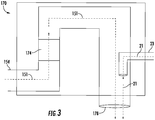
- FIG. 3 shows exhaust 21 from the first engine 26 entering the single exhaust system 170 through the first exhaust passage 23 and exhaust 151 from the second engine 150 entering the single exhaust system 170 from the second exhaust passage 154.
- Exhaust 151 from the second engine 150 will pass through a catalytic converter 174 containing a catalyst to convert pollutants within the exhaust 151 from the second engine 150 and then the exhaust 151 will be expelled out the single exhaust exit 178.
- the first exhaust passage 23 fluidly connects to the second exhaust passage 154 within the single exhaust system 170 and allows exhaust 21 from the first engine 26 to enter the second exhaust passage 154 and then exit the second exhaust passage 154 through the single exhaust exit 178.
- the first exhaust passage 23 fluidly connects to the second exhaust passage 154 downstream of the catalytic converter 174, such that the exhaust 21 from the first engine 26 does not pass through the catalytic converter 174.
- the first exhaust passage 23 fluidly connects to the second exhaust passage 154 upstream of the catalytic converter 174, such that the exhaust 21 from the first engine 26 does pass through the catalytic converter 174.
- the exhaust 21 from the first engine 26 may need to pass through the catalytic converter 174 in the second exhaust passage 154 if the first engine 26 does not contain a catalytic converter or similar system.
- FIG. 4 shows a flow chart of method 400 of operating a transport refrigeration system 200, in accordance with an embodiment of the disclosure.
- a refrigeration unit 22 is powered using a first engine 26.
- the refrigeration unit 22 is in operative association with a refrigerated cargo space 119 and provides conditioned air to the refrigerated cargo space 119.
- exhaust 21 is transported away from the first engine 26 using a first exhaust passage 23 fluidly connected to the first engine 26.
- a vehicle 102 is powered using a second engine 150. The vehicle 102 being connected to the refrigerated cargo space 119.
- exhaust 151 is transported away from the second engine 150 using a second exhaust passage 154.
- the first exhaust passage 23 is fluidly connected to the second exhaust passage 154.
- the second exhaust passage 154 includes a catalytic converter 174 and the first exhaust passage 23 may be fluidly connected to the second exhaust passage 154 downstream of the catalytic converter 174.
- the first exhaust passage 23 may be fluidly connected to the second exhaust passage 154 upstream of the catalytic converter 174.
- exhaust 21 from the first engine 26 and exhaust 151 from the second engine 150 is expelled through a single exhaust exit 178 located in the second exhaust passage 154.
- embodiments can be in the form of processor-implemented processes and devices for practicing those processes, such as a processor.
- Embodiments can also be in the form of computer program code containing instructions embodied in tangible media, such as network cloud storage, SD cards, flash drives, floppy diskettes, CD ROMs, hard drives, or any other computer-readable storage medium, wherein, when the computer program code is loaded into and executed by a computer, the computer becomes a device for practicing the embodiments.
- Embodiments can also be in the form of computer program code, for example, whether stored in a storage medium, loaded into and/or executed by a computer, or transmitted over some transmission medium, loaded into and/or executed by a computer, or transmitted over some transmission medium, such as over electrical wiring or cabling, through fiber optics, or via electromagnetic radiation, wherein, when the computer program code is loaded into an executed by a computer, the computer becomes an device for practicing the embodiments.
- the computer program code segments configure the microprocessor to create specific logic circuits.
Description
- The subject matter disclosed herein generally relates to the field of transportation refrigeration systems, and more particularly to an apparatus and method of operating the exhaust systems of such transport refrigeration systems.
- Typically, cold chain distribution systems are used to transport and distribute cargo, or more specifically perishable goods and environmentally sensitive goods (herein referred to as perishable goods) that may be susceptible to temperature, humidity, and other environmental factors. Perishable goods may include but are not limited to fruits, vegetables, grains, beans, nuts, eggs, dairy, seed, flowers, meat, poultry, fish, ice, and pharmaceuticals. Advantageously, cold chain distribution systems allow perishable goods to be effectively transported and distributed without damage or other undesirable effects.
- Refrigerated vehicles and trailers are commonly used to transport perishable goods in a cold chain distribution system. A transport refrigeration system is mounted to the vehicles or to the trailer in operative association with a cargo space defined within the vehicles or trailer for maintaining a controlled temperature environment within the cargo space.
- Conventionally, transport refrigeration systems used in connection with refrigerated vehicles and refrigerated trailers include a transport refrigeration unit having a refrigerant compressor, a condenser with one or more associated condenser fans, an expansion device, and an evaporator with one or more associated evaporator fans, which are connected via appropriate refrigerant lines in a closed refrigerant flow circuit. Air or an air/ gas mixture is drawn from the interior volume of the cargo space by means of the evaporator fan(s) associated with the evaporator, passed through the airside of the evaporator in heat exchange relationship with refrigerant whereby the refrigerant absorbs heat from the air, thereby cooling the air. The cooled air is then supplied back to the cargo space.
- On commercially available transport refrigeration systems used in connection with refrigerated vehicles and refrigerated trailers, the compressor, and typically other components of the transport refrigeration unit, must be powered during transit by a prime mover. In mechanically driven transport refrigeration systems the compressor is driven by the prime mover, either through a direct mechanical coupling or a belt drive, and other components, such as the condenser and evaporator fans are belt driven.
- An "all electric" transport refrigeration system for a refrigerated trailer application is also commercially available through Carrier Corporation. In the all electric transport refrigeration system, a prime mover carried on and considered part of the transport refrigeration system, drives an AC synchronous generator that generates AC power. The generated AC power is used to power an electric compressor motor for driving the refrigerant compressor of the transport refrigeration unit and also powering electric AC fan motors for driving the condenser and evaporator motors and electric heaters associated with the evaporator.
- The prime mover typically is an engine carried on and considered part of the transport refrigeration unit, while the vehicle includes a separate engine to power the vehicle. Commonly, the engine of the vehicle and the engine of the transport refrigeration unit have separate exhaust lines.
-
WO 2016/111960 A1 discloses a fuel cooling system comprising a refrigeration unit and a power generation system including a fuel tank fluidly coupled to an engine, wherein a fuel cooling circuit is fluidly coupled between the fuel tank and the engine. - According to one aspect of the invention, a transport refrigeration system is provided. The transport refrigeration system comprises: a vehicle having a refrigerated cargo space; a refrigeration unit in operative association with the refrigerated cargo space, the refrigeration unit providing conditioned air to the refrigerated cargo space; a first engine configured to power the refrigeration unit; a first exhaust passage fluidly connected to the first engine and configured to transport exhaust from the first engine; a second engine configured to power the vehicle; and a second exhaust passage fluidly connected to the second engine and configured to transport exhaust from the second engine to a single exhaust exit; wherein the first exhaust passage fluidly connects to the second exhaust passage such that exhaust from the first engine is transported from the first exhaust passage to the single exhaust exit through the second exhaust passage.
- Optionally, further embodiments may include: a catalytic convertor located within the second exhaust passage such that exhaust transport from the second engine to the single exhaust exit flows through the catalytic converter.
- Optionally, further embodiments may include that the first exhaust passage is fluidly connected to the second exhaust passage downstream of the catalytic converter.
- Optionally, further embodiments may include that the first exhaust passage is fluidly connected to the second exhaust passage upstream of the catalytic converter.
- Optionally, further embodiments may include that the first exhaust passage is located below the refrigeration unit.
- According to another aspect of the invention, a method of operating a transport refrigeration system is provided. The method comprises: powering a refrigeration unit using a first engine, the refrigeration unit being in operative association with a refrigerated cargo space and provides conditioned air to the refrigerated cargo space; transporting exhaust away from the first engine using a first exhaust passage fluidly connected to the first engine; powering a vehicle using a second engine, the vehicle being connected to the refrigerated cargo space; transporting exhaust away from the second engine using a second exhaust passage, wherein the first exhaust passage is fluidly connected to the second exhaust passage; and expelling exhaust from the first engine and the second engine through a single exhaust exit located in the second exhaust passage.
- Optionally, further embodiments may include: flowing exhaust from the second engine through a catalytic convertor located in the second exhaust passage.
- Optionally, further embodiments may include that the first exhaust passage is fluidly connected to the second exhaust passage downstream of the catalytic converter.
- Optionally, further embodiments may include that the first exhaust passage is fluidly connected to the second exhaust passage upstream of the catalytic converter.
- Optionally, further embodiments may include that the first exhaust passage is located below the refrigeration unit.
- Technical effects of embodiments of the present invention include utilizing the exhaust passage of the vehicle to convey exhaust from a transportation refrigeration unit to a single exhaust exit.
- The foregoing features and elements may be combined in various combinations without exclusivity, unless expressly indicated otherwise, and within the scope of the claims. These features and elements as well as the operation thereof will become more apparent in light of the following description and the accompanying drawings. It should be understood, however, that the following description and drawings are intended to be illustrative and explanatory in nature and non-limiting.
- The following descriptions should not be considered limiting in any way. With reference to the accompanying drawings, like elements are numbered alike:
-
FIG. 1 is a schematic illustration of a transport refrigeration system having a single exhaust system, according to an embodiment of the present disclosure; -
FIG. 2 is an enlarged schematic illustration of the transport refrigeration system ofFIG. 1 , according to an embodiment of the present disclosure; -
FIG. 3 is a schematic illustration of the exhaust system of the transport refrigeration system ofFIG. 1 , according to an embodiment of the present disclosure; and -
FIG. 4 is a flow diagram illustrating a method of operating a transportation refrigeration system, according to an embodiment of the present disclosure. - A detailed description of one or more embodiments of the disclosed apparatus and method are presented herein by way of exemplification and not limitation with reference to the Figures.
- Referring to
FIGs. 1-2 .FIG. 1 shows a schematic illustration of atransport refrigeration system 200 andFIG. 2 shows an enlarged schematic illustration of thetransport refrigeration system 200 ofFIG. 1 . Thetransport refrigeration system 200 is being illustrated as atrailer system 100 as seen inFIG. 1 . Thetrailer system 100 includes avehicle 102 and atransport container 106. Thevehicle 102 includes an operator's compartment orcab 104 and asecond engine 150 which acts as the drive system of thetrailer system 100. Thesecond engine 150 may include anengine controller 152 configured to control the operation of thesecond engine 150. Theengine controller 152 may be an electronic controller including a processor and an associated memory comprising computer-executable instructions that, when executed by the processor, cause the processor to perform various operations. The a processor may be but is not limited to a single-processor or multi-processor system of any of a wide array of possible architectures, including field programmable gate array (FPGA), central processing unit (CPU), application specific integrated circuits (ASIC), digital signal processor (DSP) or graphics processing unit (GPU) hardware arranged homogenously or heterogeneously. The memory may be a storage device such as, for example, a random access memory (RAM), read only memory (ROM), or other electronic, optical, magnetic or any other computer readable medium - The fuel that powers the
second engine 150 may be at least one of diesel, gasoline, compressed natural gas, and liquefied natural gas. In an embodiment, the fuel is compressed natural gas. In the illustrated embodiment, the fuel to power thesecond engine 150 of thevehicle 102 is stored in a plurality ofsecond fuel tanks 350. The plurality ofsecond fuel tanks 350 are fluidly connected to thesecond engine 150 through asecond fuel line 352. The plurality ofsecond fuel tanks 350 are configured to supply fuel to thesecond engine 150 through thesecond fuel line 352. Thetransport container 106 is coupled to thevehicle 102. Thetransport container 106 is a refrigerated trailer and includes atop wall 108, a directly opposedbottom wall 110, opposedside walls 112, and afront wall 114, with thefront wall 114 being closest to thevehicle 102. Thetransport container 106 further includes a door ordoors 117 at arear wall 116, opposite thefront wall 114. The walls of thetransport container 106 define a refrigeratedcargo space 119. It is appreciated by those of skill in the art that embodiments described herein may be applied to non-trailer refrigeration such as, for example a rigid truck or a truck having refrigerate compartment. - Typically,
transport refrigeration systems 200 are used to transport and distribute perishable goods and environmentally sensitive goods (herein referred to as perishable goods 118). Theperishable goods 118 may include but are not limited to fruits, vegetables, grains, beans, nuts, eggs, dairy, seed, flowers, meat, poultry, fish, ice, blood, pharmaceuticals, or any other suitable cargo requiring temperature controlled transport. - As seen in
FIG. 2 , thetransport refrigeration system 200 includes arefrigeration unit 22, anelectric generation device 24, afirst engine 26 for driving theelectric generation device 24, and acontroller 30. Therefrigeration unit 22 functions, under the control of thecontroller 30, to establish and regulate desired environmental parameter(s), such as, for example temperature, pressure, humidity, carbon dioxide, ethylene, ozone, light exposure, vibration exposure, and other conditions in the refrigeratedcargo space 119 as known to one of ordinary skill in the art. In an embodiment, therefrigeration unit 22 is a refrigeration system capable of providing a desired temperature and humidity range. - The
refrigeration unit 22 includes arefrigerant compression device 32, a refrigerant heatrejection heat exchanger 34, anexpansion device 36, and a refrigerant heatabsorption heat exchanger 38 connected in refrigerant flow communication in a closed loop refrigerant circuit and arranged in a conventional refrigeration cycle. Therefrigeration unit 22 also includes one ormore fans 40 associated with the refrigerant heatrejection heat exchanger 34 and driven by fan motor(s) 42 and one ormore fans 44 associated with the refrigerant heatabsorption heat exchanger 38 and driven by fan motor(s) 46. Therefrigeration unit 22 may also include aheater 48 associated with the refrigerant heatabsorption heat exchanger 38. In an embodiment, theheater 48 may be an electric resistance heater. It is to be understood that other components (not shown) may be incorporated into the refrigerant circuit as desired, including for example, but not limited to, a suction modulation valve, a receiver, a filter/dryer, an economizer circuit. - The refrigerant heat
rejection heat exchanger 34 may, for example, comprise one or more refrigerant conveying coiled tubes or one or more tube banks formed of a plurality of refrigerant conveying tubes across flow path to theheat outlet 142. The fan(s) 40 are operative to pass air, typically ambient air, across the tubes of the refrigerant heatrejection heat exchanger 34 to cool refrigerant vapor passing through the tubes. The refrigerant heatrejection heat exchanger 34 may operate either as a refrigerant condenser, such as if therefrigeration unit 22 is operating in a subcritical refrigerant cycle or as a refrigerant gas cooler, such as if therefrigeration unit 22 is operating in a transcritical cycle. - The refrigerant heat
absorption heat exchanger 38 may, for example, also comprise one or more refrigerant conveying coiled tubes or one or more tube banks formed of a plurality of refrigerant conveying tubes extending across flow path from areturn air inlet 136. The fan(s) 44 are operative to pass air drawn from the refrigeratedcargo space 119 across the tubes of the refrigerant heatabsorption heat exchanger 38 to heat and evaporate refrigerant liquid passing through the tubes and cool the air. The air cooled in traversing the refrigerant heatrejection heat exchanger 38 is supplied back to the refrigeratedcargo space 119 through arefrigeration unit outlet 140. It is to be understood that the term "air" when used herein with reference to the atmosphere within the cargo box includes mixtures of air with other gases, such as for example, but not limited to, nitrogen or carbon dioxide, sometimes introduced into a refrigerated cargo box for transport of perishable produce. - The
refrigerant compression device 32 may comprise a single-stage or multiple-stage compressor such as, for example, a reciprocating compressor or a scroll compressor. Thecompression device 32 has a compression mechanism (not shown) driven by anelectric motor 50. In an embodiment, themotor 50 may be disposed internally within the compressor with a drive shaft interconnected with a shaft of the compression mechanism, all sealed within a common housing of thecompression device 32. - The
transport refrigeration system 200 also includes acontroller 30 configured for controlling operation of thetransport refrigeration system 200 including, but not limited to, operation of various components of therefrigerant unit 22 to provide and maintain a desired thermal environment within the refrigeratedcargo space 119. Thecontroller 30 may also be able to selectively operate thefirst engine 26, typically through anelectronic engine controller 54 operatively associated with thefirst engine 26. Thecontroller 30 and theengine controller 54 may be electronic controllers including a processor and an associated memory comprising computer-executable instructions that, when executed by the processor, cause the processor to perform various operations. The a processor may be but is not limited to a single-processor or multi-processor system of any of a wide array of possible architectures, including field programmable gate array (FPGA), central processing unit (CPU), application specific integrated circuits (ASIC), digital signal processor (DSP) or graphics processing unit (GPU) hardware arranged homogenously or heterogeneously. The memory may be a storage device such as, for example, a random access memory (RAM), read only memory (ROM), or other electronic, optical, magnetic or any other computer readable medium. - The
refrigeration unit 22 has a plurality of power demand loads, including, but not limited to, the compressiondevice drive motor 50, thedrive motor 42 for thefan 40 associated with the refrigerant heatrejection heat exchanger 34, and thedrive motor 46 for thefan 44 associated with the refrigerant heatabsorption heat exchanger 38. In the depicted embodiment, theheater 48 also constitutes a power demand load. Theelectric resistance heater 48 may be selectively operated by thecontroller 30 whenever a control temperature within the temperature controlled cargo box drops below a preset lower temperature limit, which may occur in a cold ambient environment. In such an event thecontroller 30 would activate theheater 48 to heat air circulated over theheater 48 by the fan(s) 44 associated with the refrigerant heatabsorption heat exchanger 38. Theheater 48 may also be used to de-ice thereturn air intake 136. - The
first engine 26 is an on-board fossil-fuel engine that drives theelectric generation device 24, which generates electrical power. The fuel that powers thefirst engine 26 may be at least one of diesel, gasoline, compressed natural gas and liquefied natural gas. In an embodiment, the fuel is compressed natural gas. In another embodiment, the fuel that powers thefirst engine 26 is the same fuel that powers thesecond engine 150 of thevehicle 102 inFIG. 1 . In the illustrated embodiment ofFIG. 1 , the fuel to power thefirst engine 26 is stored in a plurality offirst fuel tanks 330. The plurality offirst fuel tanks 330 are fluidly connected to thefirst engine 26 through afirst fuel line 332. The plurality offirst fuel tanks 330 are configured to supply fuel to thefirst engine 26 through thefirst fuel line 332. - The drive shaft of the engine drives the shaft of the
electric generation device 24. In an electrically powered embodiment of the refrigeration unit 20, theelectric generation device 24 may comprise a single on-board, engine driven AC generator configured to generate alternating current (AC) power including at least one AC voltage at one or more frequencies. In an embodiment, theelectric generation device 24 may, for example, be a permanent magnet AC generator or a synchronous AC generator. In another embodiment, theelectric generation device 24 may comprise a single on-board, engine driven DC generator configured to generate direct current (DC) power at at least one voltage. Some electric generation devices may have internal voltage regulators while other electric generation devices do not. As each of thefan motors device drive motor 50 may be an AC motor or a DC motor, it is to be understood thatvarious power converters 52, such as AC to DC rectifiers, DC to AC inverters, AC to AC voltage/frequency converters, and DC to DC voltage converters, may be employed in connection with theelectric generation device 24 as appropriate. Thetransport refrigeration system 200 may include avoltage sensor 28 to sense the voltage of theelectric generation device 24. - Airflow is circulated into and through the
refrigerate cargo space 119 of thetransport container 106 by means of therefrigeration unit 22. Areturn airflow 134 flows into therefrigeration unit 22 from the refrigeratedcargo space 119 through the refrigeration unitreturn air intake 136, and across the refrigerant heatabsorption heat exchanger 38 via thefan 44, thus conditioning thereturn airflow 134 to a selected or predetermined temperature. The conditionedreturn airflow 134, now referred to assupply airflow 138, is supplied into therefrigerated cargo space 119 of thetransport container 106 through therefrigeration unit outlet 140, which in some embodiments is located near thebottom wall 110 of thecontainer system 106.Heat 135 is removed from the refrigerant heatrejection heat exchanger 34 through theheat outlet 142. Therefrigeration unit 22 may contain anexternal air inlet 144, as shown inFIG. 2 , to aid in the removal ofheat 135 from the refrigerant heatrejection heat exchanger 34 by pulling inexternal air 137. Thesupply airflow 138 cools theperishable goods 118 in the refrigeratedcargo space 119 of thetransport container 106. It is to be appreciated that therefrigeration unit 22 can further be operated in reverse to warm thecontainer system 106 when, for example, the outside temperature is very low. In the illustrated embodiment, thereturn air intake 136, therefrigeration unit outlet 140, theheat outlet 142, and theexternal air inlet 144 are configured as grilles to help prevent foreign objects from entering therefrigeration unit 22. - Further, in the illustrated embodiment of
FIG. 1 , thetransport refrigeration system 200 includes asingle filling point 310. Thesingle filling point 310 is fluidly connected to the plurality ofsecond fuel tanks 350 and the plurality offirst fuel tanks 330 through afilling line 312. Thesingle filling point 310 is configured to receive fuel from a filling station, such as for example a gas station. When thesingle filling point 310 receives fuel, thesingle filling point 310 distributes the fuel received to the plurality ofsecond fuel tanks 350 and the plurality offirst fuel tanks 330. It is understood that the embodiments disclosed herein may be applied to therefrigeration system 200 with more than one filling point and are not limited to having asingle point 310. - Further, in the illustrated embodiment of
FIG. 1 , thetransport refrigeration system 200 includes asingle exhaust system 170. The first engine 26 (seeFIG. 2 ) produces exhaust 21(seeFIG. 3 ) as a byproduct from the combustion of fuel from thefirst fuel tanks 330. Theexhaust 21 from thefirst engine 26 is transported through afirst exhaust passage 23 fluidly connecting thefirst engine 26 to thesingle exhaust system 170. In an embodiment, thefirst exhaust passage 23 is located below therefrigeration unit 22. Advantageously, locating thefirst exhaust passage 23 below the refrigeration unit helps avoid clearance issues as thevehicle 102 may be required to pass under low hanging objects, such as, for example, bridges. - The
second engine 150 produces exhaust 151 (seeFIG. 3 ) as a byproduct from the combustion of fuel from thesecond fuel tanks 350. Theexhaust 151 from thesecond engine 150 is transported through asecond exhaust passage 154 fluidly connecting thesecond engine 150 to a single exhaust exit located within thesingle exhaust system 170. Thefirst exhaust passage 23 fluidly connects to thesecond exhaust passage 154 within thesinge exhaust system 170 such that theexhaust 21 from thefirst engine 26 and theexhaust 151 from thesecond engine 150 exits thesingle exhaust system 170 through thesingle exhaust exit 178. - Referring now to
FIG. 3 with continued reference toFIGs. 1 and2 .FIG. 3 showsexhaust 21 from thefirst engine 26 entering thesingle exhaust system 170 through thefirst exhaust passage 23 andexhaust 151 from thesecond engine 150 entering thesingle exhaust system 170 from thesecond exhaust passage 154. Exhaust 151 from thesecond engine 150 will pass through acatalytic converter 174 containing a catalyst to convert pollutants within theexhaust 151 from thesecond engine 150 and then theexhaust 151 will be expelled out thesingle exhaust exit 178. As seen inFIG. 3 , thefirst exhaust passage 23 fluidly connects to thesecond exhaust passage 154 within thesingle exhaust system 170 and allowsexhaust 21 from thefirst engine 26 to enter thesecond exhaust passage 154 and then exit thesecond exhaust passage 154 through thesingle exhaust exit 178. In an embodiment, thefirst exhaust passage 23 fluidly connects to thesecond exhaust passage 154 downstream of thecatalytic converter 174, such that theexhaust 21 from thefirst engine 26 does not pass through thecatalytic converter 174. In an alternate embodiment, thefirst exhaust passage 23 fluidly connects to thesecond exhaust passage 154 upstream of thecatalytic converter 174, such that theexhaust 21 from thefirst engine 26 does pass through thecatalytic converter 174. Theexhaust 21 from thefirst engine 26 may need to pass through thecatalytic converter 174 in thesecond exhaust passage 154 if thefirst engine 26 does not contain a catalytic converter or similar system. - Referring now to
FIG. 4 , with continued reference toFIGs. 1-3 .FIG. 4 shows a flow chart ofmethod 400 of operating atransport refrigeration system 200, in accordance with an embodiment of the disclosure. Atblock 404, arefrigeration unit 22 is powered using afirst engine 26. Therefrigeration unit 22 is in operative association with arefrigerated cargo space 119 and provides conditioned air to the refrigeratedcargo space 119. Atblock 406,exhaust 21 is transported away from thefirst engine 26 using afirst exhaust passage 23 fluidly connected to thefirst engine 26. Atblock 408, avehicle 102 is powered using asecond engine 150. Thevehicle 102 being connected to the refrigeratedcargo space 119. - At
block 410,exhaust 151 is transported away from thesecond engine 150 using asecond exhaust passage 154. As discussed above, thefirst exhaust passage 23 is fluidly connected to thesecond exhaust passage 154. As further discussed above, thesecond exhaust passage 154 includes acatalytic converter 174 and thefirst exhaust passage 23 may be fluidly connected to thesecond exhaust passage 154 downstream of thecatalytic converter 174. In an alternate embodiment, thefirst exhaust passage 23 may be fluidly connected to thesecond exhaust passage 154 upstream of thecatalytic converter 174. Atblock 412,exhaust 21 from thefirst engine 26 andexhaust 151 from thesecond engine 150 is expelled through asingle exhaust exit 178 located in thesecond exhaust passage 154. - While the above description has described the flow process of
FIG. 4 in a particular order, it should be appreciated that unless otherwise specifically required in the attached claims that the ordering of the steps may be varied. - As described above, embodiments can be in the form of processor-implemented processes and devices for practicing those processes, such as a processor. Embodiments can also be in the form of computer program code containing instructions embodied in tangible media, such as network cloud storage, SD cards, flash drives, floppy diskettes, CD ROMs, hard drives, or any other computer-readable storage medium, wherein, when the computer program code is loaded into and executed by a computer, the computer becomes a device for practicing the embodiments. Embodiments can also be in the form of computer program code, for example, whether stored in a storage medium, loaded into and/or executed by a computer, or transmitted over some transmission medium, loaded into and/or executed by a computer, or transmitted over some transmission medium, such as over electrical wiring or cabling, through fiber optics, or via electromagnetic radiation, wherein, when the computer program code is loaded into an executed by a computer, the computer becomes an device for practicing the embodiments. When implemented on a general-purpose microprocessor, the computer program code segments configure the microprocessor to create specific logic circuits.
- The term "about" is intended to include the degree of error associated with measurement of the particular quantity based upon the equipment available at the time of filing the application. For example, "about" can include a range of ± 8% or 5%, or 2% of a given value.
- The terminology used herein is for the purpose of describing particular embodiments only and is not intended to be limiting of the present disclosure. As used herein, the singular forms "a", "an" and "the" are intended to include the plural forms as well, unless the context clearly indicates otherwise. It will be further understood that the terms "comprises" and/or "comprising," when used in this specification, specify the presence of stated features, integers, steps, operations, elements, and/or components, but do not preclude the presence or addition of one or more other features, integers, steps, operations, element components, and/or groups thereof.
- While the present invention has been described with reference to an exemplary embodiment or embodiments, it will be understood by those skilled in the art that various changes may be made and equivalents may be substituted for elements thereof without departing from the scope of the present invention as defined by the claims. In addition, many modifications may be made to adapt a particular situation or material to the teachings of the present invention without departing from the scope thereof as defined by the claims. Therefore, it is intended that the present invention not be limited to the particular embodiment disclosed as the best mode contemplated for carrying out this present invention, but that the present invention will include all embodiments falling within the scope of the claims.
Claims (10)
- A transport refrigeration system (200) comprising:a vehicle (102) having a refrigerated cargo space (119);a refrigeration unit (22) in operative association with the refrigerated cargo space, the refrigeration unit providing conditioned air to the refrigerated cargo space;a first engine (26) configured to power the refrigeration unit;a first exhaust passage (23) fluidly connected to the first engine and configured to transport exhaust (21) from the first engine;a second engine (150) configured to power the vehicle; anda second exhaust passage (154) fluidly connected to the second engine and configured to transport exhaust (151) from the second engine to a single exhaust exit (178);characterized in that the first exhaust passage (23) fluidly connects to the second exhaust passage (154) such that exhaust (21) from the first engine is transported from the first exhaust passage to the single exhaust exit (178) through the second exhaust passage (154).
- The transport refrigeration system (200) of claim 1, further comprising:
a catalytic convertor (174) located within the second exhaust passage (154) such that exhaust transported from the second engine (150) to the single exhaust exit (178) flows through the catalytic converter. - The transport refrigeration system (200) of claim 2, wherein:
the first exhaust passage (23) is fluidly connected to the second exhaust passage (154) downstream of the catalytic converter (174). - The transport refrigeration system (200) of claim 2, wherein:
the first exhaust passage (23) is fluidly connected to the second exhaust passage (154) upstream of the catalytic converter (174). - The transport refrigeration system (200) of any preceding claim, wherein:
the first exhaust passage (23) is located below the refrigeration unit (22). - A method (400) of operating a transport refrigeration system (200), the method comprising:powering (404) a refrigeration unit (22) using a first engine (26), the refrigeration unit being in operative association with a refrigerated cargo space (119) and providing conditioned air to the refrigerated cargo space;transporting (406) exhaust (21) away from the first engine using a first exhaust passage (23) fluidly connected to the first engine;powering (408) a vehicle (102) using a second engine (150), the vehicle being connected to the refrigerated cargo space (119);transporting (410) exhaust (151) away from the second engine (150) using a second exhaust passage (154), characterized in the first exhaust passage (23) is fluidly connected to the second exhaust passage (154); andexpelling (412) exhaust from the first engine and the second engine through a single exhaust exit (178) located in the second exhaust passage (154).
- The method (400) of claim 6, wherein prior to the expelling (412), the method further comprises:
flowing exhaust (151) from the second engine (150) through a catalytic convertor (174) located in the second exhaust passage (154). - The method (400) of claim 7, wherein:
the first exhaust passage (23) is fluidly connected to the second exhaust passage (154) downstream of the catalytic converter (174). - The method (400) of claim 7, wherein:
the first exhaust passage (23) is fluidly connected to the second exhaust passage (154) upstream of the catalytic converter (174). - The method (400) of any of claims 6 to 9, wherein:
the first exhaust passage (23) is located below the refrigeration unit (22).
Applications Claiming Priority (1)
| Application Number | Priority Date | Filing Date | Title |
|---|---|---|---|
| PCT/IB2017/001217 WO2019034902A1 (en) | 2017-08-18 | 2017-08-18 | Common exhaust passage for transport refrigeration unit and vehicle |
Publications (2)
| Publication Number | Publication Date |
|---|---|
| EP3668741A1 EP3668741A1 (en) | 2020-06-24 |
| EP3668741B1 true EP3668741B1 (en) | 2021-09-29 |
Family
ID=60083357
Family Applications (1)
| Application Number | Title | Priority Date | Filing Date |
|---|---|---|---|
| EP17783990.9A Active EP3668741B1 (en) | 2017-08-18 | 2017-08-18 | Common exhaust passage for transport refrigeration unit and vehicle |
Country Status (4)
| Country | Link |
|---|---|
| US (1) | US11571964B2 (en) |
| EP (1) | EP3668741B1 (en) |
| CN (1) | CN111212752B (en) |
| WO (1) | WO2019034902A1 (en) |
Families Citing this family (1)
| Publication number | Priority date | Publication date | Assignee | Title |
|---|---|---|---|---|
| US10920681B2 (en) * | 2016-12-13 | 2021-02-16 | Carrier Corporation | Pressure control valve system |
Family Cites Families (25)
| Publication number | Priority date | Publication date | Assignee | Title |
|---|---|---|---|---|
| US2475841A (en) * | 1944-06-15 | 1949-07-12 | U S Thermo Control Co | Air conditioning unit |
| US2789234A (en) * | 1956-01-16 | 1957-04-16 | Eastern Malleable Iron Company | Auxiliary power unit for vehicles |
| US4217764A (en) * | 1978-07-05 | 1980-08-19 | Sheller-Globe Corporation | Roof mounted motor vehicle air conditioner |
| EP0184685A3 (en) * | 1984-12-13 | 1987-04-08 | KANIUT, Herbert Maximilian | Split-engine for motor-vehicles, with a divided crankshaft, and an engine cross-shaft for auxiliary-drives |
| US5058704A (en) * | 1988-11-21 | 1991-10-22 | Yu Chuen Huan | Turbo jet muffler |
| US5519994A (en) * | 1994-02-18 | 1996-05-28 | Tennessee Gas Pipeline Company | Muffler with inlet pipe equalizer |
| US6223546B1 (en) * | 1999-04-21 | 2001-05-01 | Robert A. Chopko | Electrically powered transport refrigeration unit |
| DE19934790A1 (en) * | 1999-07-27 | 2001-02-08 | Bosch Gmbh Robert | Drive system for motor vehicles |
| US6306056B1 (en) * | 1999-12-17 | 2001-10-23 | Daimlerchrysler Corporation | Dual engine hybrid electric vehicle |
| US7017339B2 (en) * | 2004-03-12 | 2006-03-28 | Daimlerchrysler Corporation | Exhaust system catalyst assembly for a dual crankshaft engine |
| SE528119C2 (en) * | 2004-08-06 | 2006-09-05 | Scania Cv Ab | Arrangement for supplying a medium to an exhaust line of an internal combustion engine |
| DE102006015964A1 (en) * | 2006-04-05 | 2007-10-18 | Arvinmeritor Emissions Technologies Gmbh | Assembly for mixing a medium with the exhaust gas flow of a motor vehicle exhaust system |
| US8272432B2 (en) * | 2007-11-28 | 2012-09-25 | GM Global Technology Operations LLC | HVAC thermal storage for hybrid vehicle |
| US7971433B2 (en) * | 2008-02-14 | 2011-07-05 | Ford Global Technologies, Llc | Helical exhaust passage |
| US20100146956A1 (en) * | 2008-12-11 | 2010-06-17 | Grudynski Iii John M | Automotive exhaust system |
| JP5864901B2 (en) * | 2011-05-19 | 2016-02-17 | 日野自動車株式会社 | Manual regeneration of particulate filter |
| US8932530B2 (en) * | 2011-12-27 | 2015-01-13 | Komatsu Ltd. | Reducing agent aqueous solution mixing device and exhaust gas post-treatment device |
| US8851494B1 (en) * | 2012-01-11 | 2014-10-07 | Christopher E. Strang | Combined step/muffler housing for a land vehicle |
| EP2847528B1 (en) * | 2012-05-10 | 2019-05-01 | Carrier Corporation | Supply air discharge for a refrigerated container |
| JP2014234735A (en) * | 2013-05-31 | 2014-12-15 | ヤマハ発動機株式会社 | Motorcycle |
| DE102014014316B3 (en) * | 2014-10-01 | 2016-02-25 | Winter Fahrzeugtechnik GmbH | Vans for pharmaceuticals and chemicals |
| US20170370332A1 (en) | 2015-01-07 | 2017-12-28 | Carrier Corporation | Fuel cooling system and method |
| US20180100415A9 (en) | 2015-04-22 | 2018-04-12 | Carrier Corporation | Systems of preventing engine bearing damage |
| US9689295B1 (en) * | 2016-01-29 | 2017-06-27 | Ford Global Technologies, Llc | Method and system for exhaust gas heat recovery |
| DE102016121672A1 (en) * | 2016-11-11 | 2018-05-17 | Rheinmetall Landsysteme Gmbh | Drive for vehicles, in particular combat vehicles |
-
2017
- 2017-08-18 EP EP17783990.9A patent/EP3668741B1/en active Active
- 2017-08-18 CN CN201780096052.5A patent/CN111212752B/en active Active
- 2017-08-18 US US16/638,316 patent/US11571964B2/en active Active
- 2017-08-18 WO PCT/IB2017/001217 patent/WO2019034902A1/en unknown
Also Published As
| Publication number | Publication date |
|---|---|
| US20200164738A1 (en) | 2020-05-28 |
| CN111212752A (en) | 2020-05-29 |
| EP3668741A1 (en) | 2020-06-24 |
| CN111212752B (en) | 2023-06-23 |
| US11571964B2 (en) | 2023-02-07 |
| WO2019034902A1 (en) | 2019-02-21 |
Similar Documents
| Publication | Publication Date | Title |
|---|---|---|
| EP3472542B1 (en) | Transport refrigeration system with a battery system and corresponding method | |
| EP3472541B1 (en) | Mechanical subcooler with battery supplement | |
| EP3463961B1 (en) | Single point filling for an independent refrigeration unit driven by a separate engine | |
| US20210331559A1 (en) | Communication interface module for energy management | |
| US11548353B2 (en) | Battery powered transportation refrigeration unit with variable inverter | |
| US11472266B2 (en) | Engine exhaust gas cooling system for transport refrigeration system | |
| US11667229B2 (en) | Natural gas tank pressure control for transport refrigeration unit | |
| EP3668741B1 (en) | Common exhaust passage for transport refrigeration unit and vehicle | |
| US11117449B2 (en) | Fuel system control for refrigeration unit engine | |
| US11345210B2 (en) | High voltage auxiliary power unit for a transportation refrigeration system | |
| US20210252939A1 (en) | Automatic transportation refrigeration unit settings following real time location | |
| CN108778803B (en) | Return air inlet grille deicing method | |
| EP3833572B1 (en) | Crash detection system for transport refrigeration units | |
| EP3452752B1 (en) | Method of improving compressed natural gas tank fill |
Legal Events
| Date | Code | Title | Description |
|---|---|---|---|
| STAA | Information on the status of an ep patent application or granted ep patent |
Free format text: STATUS: UNKNOWN |
|
| STAA | Information on the status of an ep patent application or granted ep patent |
Free format text: STATUS: THE INTERNATIONAL PUBLICATION HAS BEEN MADE |
|
| PUAI | Public reference made under article 153(3) epc to a published international application that has entered the european phase |
Free format text: ORIGINAL CODE: 0009012 |
|
| STAA | Information on the status of an ep patent application or granted ep patent |
Free format text: STATUS: REQUEST FOR EXAMINATION WAS MADE |
|
| 17P | Request for examination filed |
Effective date: 20200225 |
|
| AK | Designated contracting states |
Kind code of ref document: A1 Designated state(s): AL AT BE BG CH CY CZ DE DK EE ES FI FR GB GR HR HU IE IS IT LI LT LU LV MC MK MT NL NO PL PT RO RS SE SI SK SM TR |
|
| AX | Request for extension of the european patent |
Extension state: BA ME |
|
| DAV | Request for validation of the european patent (deleted) | ||
| DAX | Request for extension of the european patent (deleted) | ||
| GRAP | Despatch of communication of intention to grant a patent |
Free format text: ORIGINAL CODE: EPIDOSNIGR1 |
|
| STAA | Information on the status of an ep patent application or granted ep patent |
Free format text: STATUS: GRANT OF PATENT IS INTENDED |
|
| INTG | Intention to grant announced |
Effective date: 20210309 |
|
| GRAS | Grant fee paid |
Free format text: ORIGINAL CODE: EPIDOSNIGR3 |
|
| GRAA | (expected) grant |
Free format text: ORIGINAL CODE: 0009210 |
|
| STAA | Information on the status of an ep patent application or granted ep patent |
Free format text: STATUS: THE PATENT HAS BEEN GRANTED |
|
| AK | Designated contracting states |
Kind code of ref document: B1 Designated state(s): AL AT BE BG CH CY CZ DE DK EE ES FI FR GB GR HR HU IE IS IT LI LT LU LV MC MK MT NL NO PL PT RO RS SE SI SK SM TR |
|
| REG | Reference to a national code |
Ref country code: GB Ref legal event code: FG4D |
|
| REG | Reference to a national code |
Ref country code: CH Ref legal event code: EP Ref country code: AT Ref legal event code: REF Ref document number: 1433903 Country of ref document: AT Kind code of ref document: T Effective date: 20211015 |
|
| REG | Reference to a national code |
Ref country code: DE Ref legal event code: R096 Ref document number: 602017046829 Country of ref document: DE |
|
| REG | Reference to a national code |
Ref country code: IE Ref legal event code: FG4D |
|
| REG | Reference to a national code |
Ref country code: NL Ref legal event code: FP |
|
| REG | Reference to a national code |
Ref country code: LT Ref legal event code: MG9D |
|
| PG25 | Lapsed in a contracting state [announced via postgrant information from national office to epo] |
Ref country code: RS Free format text: LAPSE BECAUSE OF FAILURE TO SUBMIT A TRANSLATION OF THE DESCRIPTION OR TO PAY THE FEE WITHIN THE PRESCRIBED TIME-LIMIT Effective date: 20210929 Ref country code: SE Free format text: LAPSE BECAUSE OF FAILURE TO SUBMIT A TRANSLATION OF THE DESCRIPTION OR TO PAY THE FEE WITHIN THE PRESCRIBED TIME-LIMIT Effective date: 20210929 Ref country code: HR Free format text: LAPSE BECAUSE OF FAILURE TO SUBMIT A TRANSLATION OF THE DESCRIPTION OR TO PAY THE FEE WITHIN THE PRESCRIBED TIME-LIMIT Effective date: 20210929 Ref country code: LT Free format text: LAPSE BECAUSE OF FAILURE TO SUBMIT A TRANSLATION OF THE DESCRIPTION OR TO PAY THE FEE WITHIN THE PRESCRIBED TIME-LIMIT Effective date: 20210929 Ref country code: BG Free format text: LAPSE BECAUSE OF FAILURE TO SUBMIT A TRANSLATION OF THE DESCRIPTION OR TO PAY THE FEE WITHIN THE PRESCRIBED TIME-LIMIT Effective date: 20211229 Ref country code: NO Free format text: LAPSE BECAUSE OF FAILURE TO SUBMIT A TRANSLATION OF THE DESCRIPTION OR TO PAY THE FEE WITHIN THE PRESCRIBED TIME-LIMIT Effective date: 20211229 Ref country code: FI Free format text: LAPSE BECAUSE OF FAILURE TO SUBMIT A TRANSLATION OF THE DESCRIPTION OR TO PAY THE FEE WITHIN THE PRESCRIBED TIME-LIMIT Effective date: 20210929 |
|
| REG | Reference to a national code |
Ref country code: AT Ref legal event code: MK05 Ref document number: 1433903 Country of ref document: AT Kind code of ref document: T Effective date: 20210929 |
|
| PG25 | Lapsed in a contracting state [announced via postgrant information from national office to epo] |
Ref country code: LV Free format text: LAPSE BECAUSE OF FAILURE TO SUBMIT A TRANSLATION OF THE DESCRIPTION OR TO PAY THE FEE WITHIN THE PRESCRIBED TIME-LIMIT Effective date: 20210929 Ref country code: GR Free format text: LAPSE BECAUSE OF FAILURE TO SUBMIT A TRANSLATION OF THE DESCRIPTION OR TO PAY THE FEE WITHIN THE PRESCRIBED TIME-LIMIT Effective date: 20211230 |
|
| PG25 | Lapsed in a contracting state [announced via postgrant information from national office to epo] |
Ref country code: AT Free format text: LAPSE BECAUSE OF FAILURE TO SUBMIT A TRANSLATION OF THE DESCRIPTION OR TO PAY THE FEE WITHIN THE PRESCRIBED TIME-LIMIT Effective date: 20210929 |
|
| PG25 | Lapsed in a contracting state [announced via postgrant information from national office to epo] |
Ref country code: IS Free format text: LAPSE BECAUSE OF FAILURE TO SUBMIT A TRANSLATION OF THE DESCRIPTION OR TO PAY THE FEE WITHIN THE PRESCRIBED TIME-LIMIT Effective date: 20220129 Ref country code: SK Free format text: LAPSE BECAUSE OF FAILURE TO SUBMIT A TRANSLATION OF THE DESCRIPTION OR TO PAY THE FEE WITHIN THE PRESCRIBED TIME-LIMIT Effective date: 20210929 Ref country code: RO Free format text: LAPSE BECAUSE OF FAILURE TO SUBMIT A TRANSLATION OF THE DESCRIPTION OR TO PAY THE FEE WITHIN THE PRESCRIBED TIME-LIMIT Effective date: 20210929 Ref country code: PT Free format text: LAPSE BECAUSE OF FAILURE TO SUBMIT A TRANSLATION OF THE DESCRIPTION OR TO PAY THE FEE WITHIN THE PRESCRIBED TIME-LIMIT Effective date: 20220131 Ref country code: PL Free format text: LAPSE BECAUSE OF FAILURE TO SUBMIT A TRANSLATION OF THE DESCRIPTION OR TO PAY THE FEE WITHIN THE PRESCRIBED TIME-LIMIT Effective date: 20210929 Ref country code: ES Free format text: LAPSE BECAUSE OF FAILURE TO SUBMIT A TRANSLATION OF THE DESCRIPTION OR TO PAY THE FEE WITHIN THE PRESCRIBED TIME-LIMIT Effective date: 20210929 Ref country code: EE Free format text: LAPSE BECAUSE OF FAILURE TO SUBMIT A TRANSLATION OF THE DESCRIPTION OR TO PAY THE FEE WITHIN THE PRESCRIBED TIME-LIMIT Effective date: 20210929 Ref country code: CZ Free format text: LAPSE BECAUSE OF FAILURE TO SUBMIT A TRANSLATION OF THE DESCRIPTION OR TO PAY THE FEE WITHIN THE PRESCRIBED TIME-LIMIT Effective date: 20210929 Ref country code: AL Free format text: LAPSE BECAUSE OF FAILURE TO SUBMIT A TRANSLATION OF THE DESCRIPTION OR TO PAY THE FEE WITHIN THE PRESCRIBED TIME-LIMIT Effective date: 20210929 |
|
| REG | Reference to a national code |
Ref country code: DE Ref legal event code: R097 Ref document number: 602017046829 Country of ref document: DE |
|
| PG25 | Lapsed in a contracting state [announced via postgrant information from national office to epo] |
Ref country code: DK Free format text: LAPSE BECAUSE OF FAILURE TO SUBMIT A TRANSLATION OF THE DESCRIPTION OR TO PAY THE FEE WITHIN THE PRESCRIBED TIME-LIMIT Effective date: 20210929 |
|
| PLBE | No opposition filed within time limit |
Free format text: ORIGINAL CODE: 0009261 |
|
| STAA | Information on the status of an ep patent application or granted ep patent |
Free format text: STATUS: NO OPPOSITION FILED WITHIN TIME LIMIT |
|
| 26N | No opposition filed |
Effective date: 20220630 |
|
| PG25 | Lapsed in a contracting state [announced via postgrant information from national office to epo] |
Ref country code: SI Free format text: LAPSE BECAUSE OF FAILURE TO SUBMIT A TRANSLATION OF THE DESCRIPTION OR TO PAY THE FEE WITHIN THE PRESCRIBED TIME-LIMIT Effective date: 20210929 |
|
| PG25 | Lapsed in a contracting state [announced via postgrant information from national office to epo] |
Ref country code: IT Free format text: LAPSE BECAUSE OF FAILURE TO SUBMIT A TRANSLATION OF THE DESCRIPTION OR TO PAY THE FEE WITHIN THE PRESCRIBED TIME-LIMIT Effective date: 20210929 |
|
| PG25 | Lapsed in a contracting state [announced via postgrant information from national office to epo] |
Ref country code: MC Free format text: LAPSE BECAUSE OF FAILURE TO SUBMIT A TRANSLATION OF THE DESCRIPTION OR TO PAY THE FEE WITHIN THE PRESCRIBED TIME-LIMIT Effective date: 20210929 |
|
| REG | Reference to a national code |
Ref country code: CH Ref legal event code: PL |
|
| PG25 | Lapsed in a contracting state [announced via postgrant information from national office to epo] |
Ref country code: LU Free format text: LAPSE BECAUSE OF NON-PAYMENT OF DUE FEES Effective date: 20220818 Ref country code: LI Free format text: LAPSE BECAUSE OF NON-PAYMENT OF DUE FEES Effective date: 20220831 Ref country code: CH Free format text: LAPSE BECAUSE OF NON-PAYMENT OF DUE FEES Effective date: 20220831 |
|
| REG | Reference to a national code |
Ref country code: BE Ref legal event code: MM Effective date: 20220831 |
|
| PG25 | Lapsed in a contracting state [announced via postgrant information from national office to epo] |
Ref country code: IE Free format text: LAPSE BECAUSE OF NON-PAYMENT OF DUE FEES Effective date: 20220818 |
|
| PGFP | Annual fee paid to national office [announced via postgrant information from national office to epo] |
Ref country code: NL Payment date: 20230721 Year of fee payment: 7 |
|
| PG25 | Lapsed in a contracting state [announced via postgrant information from national office to epo] |
Ref country code: BE Free format text: LAPSE BECAUSE OF NON-PAYMENT OF DUE FEES Effective date: 20220831 |
|
| PGFP | Annual fee paid to national office [announced via postgrant information from national office to epo] |
Ref country code: GB Payment date: 20230720 Year of fee payment: 7 |
|
| PGFP | Annual fee paid to national office [announced via postgrant information from national office to epo] |
Ref country code: FR Payment date: 20230720 Year of fee payment: 7 Ref country code: DE Payment date: 20230720 Year of fee payment: 7 |