EP3668334B1 - Weighted bag - Google Patents
Weighted bag Download PDFInfo
- Publication number
- EP3668334B1 EP3668334B1 EP18846134.7A EP18846134A EP3668334B1 EP 3668334 B1 EP3668334 B1 EP 3668334B1 EP 18846134 A EP18846134 A EP 18846134A EP 3668334 B1 EP3668334 B1 EP 3668334B1
- Authority
- EP
- European Patent Office
- Prior art keywords
- shell
- bag
- angling
- figures
- extending
- Prior art date
- Legal status (The legal status is an assumption and is not a legal conclusion. Google has not performed a legal analysis and makes no representation as to the accuracy of the status listed.)
- Active
Links
Images








Classifications
-
- A—HUMAN NECESSITIES
- A63—SPORTS; GAMES; AMUSEMENTS
- A63B—APPARATUS FOR PHYSICAL TRAINING, GYMNASTICS, SWIMMING, CLIMBING, OR FENCING; BALL GAMES; TRAINING EQUIPMENT
- A63B21/00—Exercising apparatus for developing or strengthening the muscles or joints of the body by working against a counterforce, with or without measuring devices
- A63B21/06—User-manipulated weights
- A63B21/0601—Special physical structures of used masses
- A63B21/0603—Fluid-like particles, e.g. gun shot or sand
-
- A—HUMAN NECESSITIES
- A63—SPORTS; GAMES; AMUSEMENTS
- A63B—APPARATUS FOR PHYSICAL TRAINING, GYMNASTICS, SWIMMING, CLIMBING, OR FENCING; BALL GAMES; TRAINING EQUIPMENT
- A63B21/00—Exercising apparatus for developing or strengthening the muscles or joints of the body by working against a counterforce, with or without measuring devices
- A63B21/06—User-manipulated weights
- A63B21/072—Dumb-bells, bar-bells or the like, e.g. weight discs having an integral peripheral handle
-
- A—HUMAN NECESSITIES
- A45—HAND OR TRAVELLING ARTICLES
- A45C—PURSES; LUGGAGE; HAND CARRIED BAGS
- A45C13/00—Details; Accessories
- A45C13/10—Arrangement of fasteners
- A45C13/1023—Arrangement of fasteners with elongated profiles fastened by sliders
- A45C13/103—Arrangement of zip-fasteners
-
- A—HUMAN NECESSITIES
- A45—HAND OR TRAVELLING ARTICLES
- A45C—PURSES; LUGGAGE; HAND CARRIED BAGS
- A45C13/00—Details; Accessories
- A45C13/26—Special adaptations of handles
-
- A—HUMAN NECESSITIES
- A45—HAND OR TRAVELLING ARTICLES
- A45C—PURSES; LUGGAGE; HAND CARRIED BAGS
- A45C13/00—Details; Accessories
- A45C13/10—Arrangement of fasteners
- A45C2013/1015—Arrangement of fasteners of hook and loop type
-
- A—HUMAN NECESSITIES
- A63—SPORTS; GAMES; AMUSEMENTS
- A63B—APPARATUS FOR PHYSICAL TRAINING, GYMNASTICS, SWIMMING, CLIMBING, OR FENCING; BALL GAMES; TRAINING EQUIPMENT
- A63B21/00—Exercising apparatus for developing or strengthening the muscles or joints of the body by working against a counterforce, with or without measuring devices
- A63B21/40—Interfaces with the user related to strength training; Details thereof
- A63B21/4027—Specific exercise interfaces
- A63B21/4033—Handles, pedals, bars or platforms
- A63B21/4035—Handles, pedals, bars or platforms for operation by hand
-
- A—HUMAN NECESSITIES
- A63—SPORTS; GAMES; AMUSEMENTS
- A63B—APPARATUS FOR PHYSICAL TRAINING, GYMNASTICS, SWIMMING, CLIMBING, OR FENCING; BALL GAMES; TRAINING EQUIPMENT
- A63B2209/00—Characteristics of used materials
-
- A—HUMAN NECESSITIES
- A63—SPORTS; GAMES; AMUSEMENTS
- A63B—APPARATUS FOR PHYSICAL TRAINING, GYMNASTICS, SWIMMING, CLIMBING, OR FENCING; BALL GAMES; TRAINING EQUIPMENT
- A63B2209/00—Characteristics of used materials
- A63B2209/10—Characteristics of used materials with adhesive type surfaces, i.e. hook and loop-type fastener
-
- A—HUMAN NECESSITIES
- A63—SPORTS; GAMES; AMUSEMENTS
- A63B—APPARATUS FOR PHYSICAL TRAINING, GYMNASTICS, SWIMMING, CLIMBING, OR FENCING; BALL GAMES; TRAINING EQUIPMENT
- A63B2210/00—Space saving
- A63B2210/50—Size reducing arrangements for stowing or transport
-
- A—HUMAN NECESSITIES
- A63—SPORTS; GAMES; AMUSEMENTS
- A63B—APPARATUS FOR PHYSICAL TRAINING, GYMNASTICS, SWIMMING, CLIMBING, OR FENCING; BALL GAMES; TRAINING EQUIPMENT
- A63B2225/00—Miscellaneous features of sport apparatus, devices or equipment
- A63B2225/62—Inflatable
Definitions
- the disclosure relates in general to weightlifting devices, and more particularly, to a weighted bag for use in various weightlifting and other exercises.
- shape changing devices include, but are not limited to shape changing platforms, such as hemispherically shaped structures which are semi-rigid, inflatable structures and the like. Other such devices include balls or bags that can be lifted, carried, thrown or otherwise manipulated.
- the present invention relates to a bag for weightlifting and similar exercises as defined in claim 1.
- a bag configured to be filled with a filler material, including a shell having a central body portion that is elongated between opposed first and second ends and has a top and a bottom extending between the first and second ends, where the central body portion and the first and second ends of the shell combine to define and enclose an inner cavity configured for containing the filler material, and where the shell has an opening providing access to the inner cavity and a closure mechanism configured for selectively opening and closing the opening, as well as a handle assembly engaged with the shell.
- the handle assembly includes a first gripping member connected to the shell proximate a first juncture between the top and the first end and a second gripping member connected to the shell proximate a second juncture between the top and the second end.
- the first gripping member extends outward from the shell at an oblique angle to at least one of the top, the first end, and the lateral centerline
- the second gripping member extends outward from the shell at an oblique angle to at least one of the top, the second end, and the lateral centerline.
- the first gripping member includes a first loop having ends connected to front and rear sides of the shell, and the second gripping member includes a second loop having ends connected to the front and rear sides of the shell.
- the shell is formed of a single panel extending around front and rear sides of the shell and connected to itself by seams at the first and second ends and a lateral seam extending between the first and second ends.
- the lateral seam extends across the rear side of the shell, and the opening is defined on the front side of the shell.
- the handle assembly further includes a first base connected to the shell and extending on the front side and the rear side of the shell and having a first crossing portion extending over the top between the front side and the rear side proximate a first juncture between the top and the first end, and a second base connected to the shell and extending on the front side and the rear side and having a second crossing portion extending over the top between the front side and the rear side proximate a second juncture between the top and the second end.
- the first gripping member is connected to the first base and extends outward from the first base
- the second gripping member is connected to the second base and extends outward from the second base.
- the first crossing portion has a first inner edge and the second crossing portion has a second inner edge, and the first and second inner edges each form angles of 80-100° with the top of the shell.
- the shell has a rectangular shape defined by the top, the bottom, and the first and second ends, and/or the shell is configured to have an oval shape when viewed from the first or second end when filled.
- the shell has a length measured between the first and second ends and a height measured between the top and the bottom, and the length is at least two times the height.
- a bag configured to be filled with a filler material, including a shell having a front side and a back side and having a central body portion and opposed first and second ends, the central body portion having a top and a bottom extending between the first and second ends, where the central body portion and the first and second ends of the shell combine to define and enclose an inner cavity configured for containing the filler material, and where the shell has an opening providing access to the inner cavity, as well as a handle assembly engaged with the shell.
- the handle assembly includes a first base connected to the shell and extending on the front side and the rear side and having a first crossing portion extending over the top between the front side and the rear side proximate a first juncture between the top and the first end, a first gripping member connected to the first base and extending outward from the first base, a second base connected to the shell and extending on the front side and the rear side and having a second crossing portion extending over the top between the front side and the rear side proximate a second juncture between the top and the second end, and a second gripping member connected to the second base and extending outward from the second base.
- the first crossing portion has a first inner edge and the second crossing portion has a second inner edge, and the first and second inner edges each form angles of 80-100° with the top of the shell.
- the first base further includes a first front angling portion extending on the front side of the shell to the top of the shell at oblique angles to the first end and the top of the shell and a first rear angling portion extending on the rear side of the shell to the top of the shell at oblique angles to the first end and the top of the shell, where the first crossing portion extends between the first front angling portion and the first rear angling portion.
- the first front angling portion extends on the front side of the shell from the first end to the top of the shell
- the first rear angling portion extends on the rear side of the shell from the first end to the top of the shell.
- the second base further includes a second front angling portion extending on the front side of the shell from the second end to the top of the shell at oblique angles to the second end and the top of the shell and a second rear angling portion extending on the rear side of the shell from the second end to the top of the shell at oblique angles to the second end and the top of the shell, where the second crossing portion extends between the second front angling portion and the second rear angling portion.
- the first crossing portion forms juncture angles with the first front angling portion and the first rear angling portion that are 110-140°.
- the first crossing portion has a first width between the first inner edge and a first outer edge of the first crossing portion, and the first front angling portion and the first rear angling portion have widths defined between inner and outer edges thereof, where the first width is smaller than the widths of the first front angling portion and the first rear angling portion.
- the first base is formed of a continuous panel, and the first base is folded over itself at the first crossing portion, such that a first surface of the continuous panel forms an outer surface of the first front angling portion and an inner surface of the first rear angling portion.
- the shell has a lateral centerline extending between the first and second ends, where the first gripping member extends outward from the first base at an oblique angle to at least one of the top, the first end, and the lateral centerline, and the second gripping member extends outward from the first base at an oblique angle to at least one of the top, the second end, and the lateral centerline.
- the first gripping member includes a first loop having ends connected to the first base on the front and rear sides of the shell and the second gripping member includes a second loop having ends connected to the second base on the front and rear sides of the shell.
- the shell is formed of a single panel extending around the front and rear sides and connected to itself by seams at the first and second ends and a lateral seam extending between the first and second ends.
- the lateral seam extends across the rear side of the shell, and the opening is defined on the front side of the shell.
- the shell has a rectangular shape defined by the top, the bottom, and the first and second ends, and/or the shell is configured to have an oval shape when viewed from the first or second end when filled.
- the weighted bag 10 includes an outer shell 12 and handle assembly 14.
- the handle assembly 14 is coupled to the outer shell 12 by two or more points along the weighted bag 10, such as by a strap assembly 70 as described herein.
- the weighted bag 10 as shown in Figures 1-8 is configured for weightlifting and similar exercises, and can be lifted, carried, thrown, dropped, and otherwise used to enhance strength, agility and the like.
- the outer shell 12 shown in Figures 1-8 , comprises one or more panels 20 that are connected by one or more seams 22, an opening 24 with a shell closure member 26.
- Each of the panels 20 has an inner surface 31 defining an inner cavity 21 configured to hold a filler material 16 and an outer surface 32 opposite the inner surface 31.
- the shell 12 has a top 38 and a bottom 39, such that the opening 24 is positioned on the top 38, and the bag 10 is configured to rest on the bottom 39. It is understood that the top 38 and the bottom 39 are relative terms that depend on the orientation of the bag 10.
- the inner surface 31 and outer surface 32 of the panels 20 may be defined by one or more surfacing layers that may be of substantially equal or variable materials. Generally, these are two or greater ply configuration coupled together. In the configuration shown, the panels are shown as singular pieces with the understanding that they may represent multiple plies of material. In one embodiment, the panels 20 are formed from a two ply construction, with the outer and inner plies comprising different grades of ballistic nylon fabric (the outside being of 1000 denier and the inside being of 500 denier). Of course, other configurations are contemplated.
- the panels 20 include at least two opposed end panels 50 and central body panel 58.
- Each end panel 50 has an outer panel 51, an inner panel 52, and slot 57 defined between the inner and outer panels 51, 52.
- the outer panel 51 is coupled to the inner panel 52 by any number of different structures, but not limited to, cross- stitching, heat sealing, adhesive, among others.
- Each slot 57 in this embodiment extends between the outer and inner panels 51, 52 and has upper and lower openings 53 to permit passage into and out of the slot 57, and the slot 57 extends continuously between the openings 53.
- the outer and inner panels 51, 52 are connected together around the exteriors of the panels 51, 52, and in other embodiments, the panels 51, 52 may have inner walls, seams, adhesives, heat sealing, or other structures that define a slot 57 that is narrower than the widths of the panels 51, 52.
- the end panels 50 are substantially parallel with each other, and the central body panel 58 extends between the end panels 50.
- the shell 12 in the embodiment of Figures 1-8 is entirely or substantially defined by the end panels 50 and the central body panel 58.
- the shell 12 defines a cylindrical configuration, having a circular cylindrical portion or central body portion 54 formed by the central body panel 58 and circular flat or bulged ends 55 formed by the end panels 50.
- the shell 12 may have a different shape, such as an oval cylinder, a cube, a rectangular cylinder, a triangular cylinder, etc.
- the cylindrical portion 54 may simply be referred to as a "central body portion" when describing a shell 12 having a cylindrical shape or any other shape.
- the relative sizes and shapes of the end panels 50 and the central body panel 58 may be different in other embodiments, and the cylindrical portion 54 and/or the ends 55 may be formed of a greater of smaller number of panels in other embodiments.
- the cylindrical portion 54 and the ends 55 may each be formed by one or more panels 22.
- the bag 10 has an opening 24 and a filling mechanism 25 that is accessible through the opening 24 for filling the bag 10.
- the opening 24 in the embodiment of Figures 1-8 is placed along the central body panel 58 in such a manner that it allows entry to the inner cavity 21 of the bag 10.
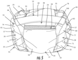
- the opening 24 shown in Figures 1 and 5 is oriented along the length of central body panel 58 at the top of the bag 10, but the opening 24 may be oriented and/or located differently in other embodiments.
- the opening 24 includes a closure member 26 (also called a shell closure member) configured for releasably closing the opening 24. When engaged, the shell closure member 26 resists the movement of filler material 16 into or out of the opening 24. In the configuration shown, the opening 24 and the shell closure member 26 are positioned directly below the natural position of the handle 60, which can reduce the stresses that are placed in the region surrounding the opening.
- the opening 24 is defined by first side edge 140, second side edge 142, first end 144, and second end 146 which collectively define the perimeter of the opening.
- the first side edge 140 and second side edge 142 are opposite and substantially parallel to each other and separated by the width of the opening 24. Further, the first end 144 and second end 146 are opposite to each other and separated by the length of the opening 24.
- the first side edge 140 and second side edge 142 are connected at their respective ends by first end 144 and second end 146.
- the first and second ends 144, 146 may be formed as V-shaped or U-shaped structures in one embodiment or may be straight linear sides that are substantially parallel to each other and perpendicular to the side edges 140, 142 in another embodiment.
- the opening 24 has an elongated rectangular configuration in the embodiment of Figures 1-8 , and the opening 24 may have a differently-shaped configuration in other embodiments.
- the shell closure member 26 is substantially planar to the opening 24 and coupled in such a way to edges of opening 24 that closure of the shell closure member 26 substantially closes the opening 24.
- the shell closure member 26, in the configuration of Figures 1-8 includes a zipper. In this configuration, the dimensions of the opening 24 are similar to the size of the shell closure member 26. In other words, the lengths of the edges of the shell closure member 26 are substantially parallel and comparable to the first side edge 140 and second side edge 142 of the opening 24. In contemplated configurations, the shell closure member 26 is secured in a manner that ensures close coupling along the entire edges 140, 142 of the opening 24.
- the shell closure member 26 may have other configurations, such as a hook and loop fastener, snaps, buttons, flaps, and other fastening and/or closing structures or combinations of such structures may be utilized. It is understood that the configuration of the shell closure member 26 may depend at least partially on the configuration of the opening 24. For example, a shell closure member 26 in the form of a zipper may not be usable or optimal with some opening 24 configurations, and another type of closure member 26 may be used.
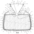
- the filling mechanism 25 includes a funnel structure 27 having a flexible encircling wall 160 forming a funnel shape, a grasping handle or grasping member 168, a filling mechanism closure member 170, and securing member 176.
- the flexible encircling wall 160 has a proximal end 161, a distal end 162, a lower exit 164, and an upper inlet 166.
- the proximal end 161 and distal end 162 are on opposite ends of the funnel 27, and the proximal end 161 is a fixed end connected to the shell 12, while the distal end 162 is a free end that can be extended out of the shell 12 through the opening 24 or retracted into the shell 12.
- the proximal end 161 is connected to the inner surface 130 of the outer shell 12, as shown in Figures 6-8 , and the connection between the proximal end 161 and the shell 12 forms a lower perimeter of the funnel 27.
- the proximal end 161 of the funnel 27 is secured to the inner surface of the shell 12 around the entire opening 24, along a connection line spaced from the opening 24. This configuration resists leakage of the filler material 16 through the connection between the proximal end 161 and the shell 12 and also provides a pocket 17 inside the opening 24 where the funnel 27 can be placed after collapsing, e.g., by folding or rolling, as described herein.
- the distal end 162 when fully extended and expanded, forms an upper perimeter of the funnel, and it is understood that the upper perimeter may be larger than the lower perimeter in one embodiment.
- the funnel 27 may have a neck or narrowest portion 163 that is located between the proximal and distal ends 161, 162 and has a perimeter and a maximum width that are smaller than the perimeters and maximum widths at the proximal and distal ends 161, 162.
- the neck 163 is located closer to the proximal end 161 than the distal end 162 and is configured to be generally located within the opening 24 when the funnel 27 is fully extended and expanded.
- the wall 160 in Figures 6-8 including the lower exit 164 and the upper inlet 166, may be substantially oval or rectangular in shape in one embodiment, but these components are subject to variable changes in length and width in contemplated configurations and desired sizes of the weighted bag 10. It is to be understood the openings (exit 164 and inlet 166) are substantially large enough to allow entry of physical materials, such as sand or polymer beads, with minimal interference or resistance from the filling mechanisms 25.
- the funnel 27 may have one or more grasping handles 168 at or near the distal end 162 to assist in pulling the funnel 27 through the opening 24 and/or opening the funnel closure 170 as described herein.
- the funnel 27 in Figures 6-8 has two grasping handles 168 on opposite sides of the inlet 166, with each grasping handle 168 in the form of a thin strap connected to the exterior of the wall 160 of the funnel 27.
- the grasping handles 168 are oriented to extend outwardly from the distal end 162 when the funnel 27 is in an open and extended position. Placement of the grasping handle 168 on the funnel is variable and subject to change in contemplated configurations of the funnel 27.
- the grasping handle 168 may be connected to the wall 160 by stitching, adhesive, or heat sealing, among other techniques, or a combination of such techniques.
- the funnel 27 also has a funnel closure 170 configured to close the inlet 166 to resist egress of the particulate material 16.
- the funnel closure 170 includes a first engaging portion 172 and second engaging portion 174 positioned on opposite sides 165, 167 of the wall 160 at the inlet 166 proximate the distal end 162 and configured to engage each other to releasably close the inlet 166.
- the first engaging portion 172 and second engaging portion 174 include elongated strips of complementary hook and loop materials that releasably connect to each other when engaged.
- the engaging portions 172, 174 when engaged, seal the sides 165, 167 to each other to close the upper inlet 166 and resist the entry or exit of material through the upper inlet 166.
- the strips forming the first and second engaging portions 172, 174 extend equal distances along the entirety of both sides of the inlet 166 to completely close the inlet 166 when engaged.
- other releasable connecting or fastening structures can be used as the funnel closure 170, such as snaps, buttons, zippers, and the like, as well as complementary structures when appropriate, or combinations of different structures.
- the funnel 27 also includes a funnel securing structure 176 configured to secure and further resist ingress or egress of material through the funnel 27.
- the funnel securing structure 176 in Figures 6-8 includes a first securing member 177 and a second securing member 178 that are configured to engage each other to releasably close the inlet 166.
- the funnel securing structure 176 in Figures 6-8 is lower on the flexible encircling wall 160 than the funnel closure 170.
- the securing members 177, 178 in this embodiment are connected to the outer surface of the flexible encircling wall 160 on opposite sides 165, 167 of the wall 160 at different distances from the distal end 162.
- the first securing member 177 is connected to the first side 165 closer to the distal end 162, and the second securing member 178 is connected to the second side 167 farther from the distal end 162.
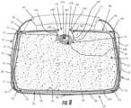
- the wall 160 is configured to be rolled or folded by rolling or folding the first side 165 over the second side 167 as shown in Figure 8 to achieve engagement of the securing members 177, 178 to releasably retain the funnel 27 in the rolled or folded position.
- the securing members 177, 178 include elongated strips of complementary hook and loop materials that releasably connect to each other when engaged.
- the size and positioning of the securing members 177, 178 may be different in other embodiments.
- the securing structure 176 may have a different configuration in other embodiments, such as any configuration of the funnel closure 170 discussed herein.
- the inner cavity 21 of the outer shell 12 has filler material 16 within it when the device is prepared for use.
- Filler material 16 is designed to be a heavy but loose and flowable material including, but not limited to, sand, polymer beads, or other such particulate materials.
- the bag 10 has an inner bag 135 connected around the opening 24 to contain the filler material 16, with seams (not shown) that define the shape of the inner bag 135 and/or connect pieces forming the inner bag 135.
- the inner bag 135 has an open end 136 that is connected to the shell 12 around the opening 24 such that the inner bag 135 is in communication with the exit 164 of the funnel 27.
- the inner bag 135 and the shell 12 may be designed differently in materials, connections (e.g., seams 22), and structure.
- the materials, connections, and structure of the shell 12 may be configured for strength, durability, abrasion resistance, and comfort in handling, while the materials, connections, and structure of the inner bag 135 may be configured primarily for strength and resisting leakage.
- the bag 10 can be filled by opening the shell closure member 26 to open the opening 24 and extending the filling mechanism 25 through the opening 24.
- the funnel 27 in Figures 6-8 can be fully extended by pulling the funnel 27 through the opening, disconnecting the securing structure 176, and then fully extending the funnel 27.
- the funnel 27 can be opened by disconnecting the closure 170 to open the inlet 166, which may be done with the assistance of the grasping handles 168. It is noted that the grasping handles may also be used to hold the upper inlet 166 open during filling.
- the filler material 16 can be filled into the cavity 21 (and the inner bag 135 if present) by entering through the upper inlet 166, travelling through the funnel 27, and exiting into the bag 10 through the lower exit 164.
- the closure 170 of the filling mechanism 25 is manipulated to close the inlet 166.
- the first and second engaging portions 172, 174 are engaged with each other to close the inlet 166 of the funnel 27.
- the filling mechanism 25 can also then be collapsed into the opening 24, using the securing structure 176 to further secure the collapsed filling mechanism 25.
- the funnel 27 is collapsed by rolling or folding the top of the flexible encircling wall 160 at such amounts and to such a degree to cause the securing members 177, 178 to engage with each other and secure the funnel 27 in a collapsed position.
- the filling mechanism 25 can then be pushed through opening 24 and into the cavity 21 of the shell 12, and the shell closure member 26 is then manipulated to close the opening 24.
- the funnel 27 is received within a pocket 17 defined below the opening 24 between the proximal end 161 of the funnel 27 and the inner surface 31 of the shell 12.
- the resultant configuration of the filling mechanism 25 is sealed against ingress and egress of material in multiple ways, including by the shell closure member 26, the filling mechanism closure 170, and the folding or rolling of the filling mechanism 25 (secured by the securing structure 176), which creates a tortuous path for the filling material 16 to escape.
- the handle assembly 14 of the bag 10 in Figures 1-8 includes a handle 60 and a strap assembly 70 including one or more straps connecting the handle 60 to the shell 12 to permit the bag 10 to be lifted by grasping the handle 60.
- the strap assembly 70 includes at least one circumferential strap 71 that extends partially or completely around the circumference of the cylindrical portion 54 of the shell 12.
- the strap assembly 70 in Figures 1-8 includes first and second circumferential or peripheral straps 71 extending around at least a portion of the periphery of the shell 12, and a central or transverse strap 80 extending around at least a portion of the periphery of the shell 12 transverse to the circumferential straps 71.
- the circumferential straps 71 as shown in Figures 1-5 extend parallel to each other around the cylindrical portion 54 of the shell 12, with the two circumferential straps 71 each located proximate one of the ends 55, and the central strap 80 extends around the cylindrical portion 54 and the circular ends 55 of the shell 12 perpendicular or transverse to both circumferential straps 71.
- circumferential is used herein with respect to a circular cylindrical structure as shown in Figures 1-8 , but that the term “peripheral” may be used to describe these straps for use with a structure that is not necessarily circular.
- circumferential and peripheral as used herein are not intended to imply that the relevant strap necessarily extends around the entire circumference or periphery of the bag 10, but only specify the direction in which the strap extends, i.e., around the circumference or periphery.
- the first and second circumferential straps 71 extend from opposite ends 66 of the handle 60 circumferentially around the periphery of the cylindrical portion 54, around the bottom 39 of the shell 12, and back toward the top 38 of the shell 12 to engage the handle 60.
- the first circumferential strap 71 in this embodiment includes a first strap portion 74 that engages the handle 60 at one end 66 and extends in a first circumferential direction around a portion of the cylindrical portion 54 of the shell 12 and a second strap portion 75 that engages the handle 60 at one end 66 and extends in a second, opposite circumferential direction around a portion of the cylindrical portion 54 of the shell 12.
- the strap portions 74, 75 of the first circumferential strap 71 are joined together at a joint 76 on the bottom 39 of the shell 12 to form a single strap 71.
- the strap portions 74, 75 may be parts of a single, integral or continuous strap 71, or may not connect together, e.g., such as by connecting to the shell 12.
- the second circumferential strap 71 in Figures 1-5 is similarly configured, including a first strap portion 77 that engages the handle 60 at one end 66 and extends in a first circumferential direction around a portion of the cylindrical portion 54 of the shell 12 and a second strap portion 78 that engages the handle 60 at one end 66 and extends in a second, opposite circumferential direction around a portion of the cylindrical portion 54 of the shell 12.
- the strap portions 77, 78 of the second circumferential strap 71 are joined together at a joint 79 on the bottom 39 of the shell 12 to form a single strap 71.
- the strap portions 77, 78 may be parts of a single, integral or continuous strap 71, or may not connect together, e.g., such as by connecting to the shell 12.
- the joints 76, 79 are formed by a combination of stitching and adhesives in one embodiment, but may be formed by additional connecting structures and techniques described herein, or combinations thereof.
- first strap portions 74, 77 of the first and second circumferential straps 71 are formed as an integral or continuous strap 72 that extends from the joint 76 into and through the handle 60 and to the other joint 79, and the second strap portions 75, 78 of the first and second circumferential straps 71 are similarly formed as an integral or continuous strap 73.
- first and second circumferential straps are all formed as part of a continuous strap, connected by the joints 76, 79.
- a "continuous" strap as used herein refers to a strap that functions or operates as a single piece (which may have joints or other junctures within), while an “integral” strap as used herein refers to a strap that is formed of a single, integral piece without joints, seams, etc.
- These straps 72, 73 each extend circumferentially around the same side of the cylindrical portion 54 proximate opposite ends 55 in this embodiment, but it is understood that in another embodiment the straps 72, 73 may cross each other within the handle 60 and extend on opposite sides.
- the strap portions 74, 75, 77, 78 in this embodiment engage the handle 60 at least by extending through the handle 60, and may be fixedly connected to the handle 60, or the handle 60 may be able to slide with respect to the strap portions 74, 75, 77, 78.
- the strap portions 74, 75, 76, 77 may be separate pieces that are separately engaged with the handle 60, or each circumferential strap 71 may itself be formed as a single piece engaged with the handle 60.
- both of the circumferential straps 71 may be formed by a single-piece strap that extends twice through the handle 60 and around both ends of the cylindrical portion 54 of the shell 12. It is understood that the engagement between the strap portions 74, 75, 77, 78 and the handle 60 and the shell 12 is sufficient that the shell 12 can be lifted by exerting an upward force on the handle 60.
- the circumferential straps 71 are connected to or engaged with the shell 12 in a slidable configuration by retaining structures 28 in the form of loop assemblies or belt loop assemblies, rather than being fixedly connected to the shell 12. It is understood that the retaining structures 28 may be referred to as loop assemblies 28 in discussing the embodiment of Figures 1-5 herein, but that other retaining structures may be used to achieve similar functionality. In another embodiment, one or both of the circumferential straps 71 may be provided in the same or a similar configuration while being fixedly connected to the shell 12, such as by stitching, adhesive, heat sealing, etc.
- the loop assemblies 28 in Figures 1-5 are positioned around the cylindrical portion 54 of the shell 12 at or proximate to the opposed ends 55, and may be referred to as a first end loop assembly 28 and a second end loop assembly 28.
- the first end loop assembly 28 secures the first circumferential strap 71 to the shell 12
- the second end loop assembly 28 secures the second circumferential strap 71 to the shell 12.
- the loop assemblies 28 in this configuration extend in both circumferential directions around the cylindrical portion 54 of the shell 12, from the top 38 to the bottom 39 of the shell 12.
- the shell 12 in Figures 1-5 also has circumferential supports 30 that are fixedly connected to the shell 12 (e.g., to the central body panel 58) circumferentially around the cylindrical portion 54 proximate the ends 55 and extend beneath the loop assemblies 28.
- the circumferential supports 30 in the embodiment of Figures 1-5 are connected to the shell 12 around the entire circumference of the shell 12 and across the entire width of each support 30, except for the locations where the circumferential supports 30 cross the opening 24 and the closure 26, where the circumferential supports 30 are connected only around the outer edge (the junctures with the end panels 50).
- the circumferential supports 30 may be made from woven nylon or other durable fabric material and may be connected to the shell 12 by stitching and adhesives in one embodiment, but may be differently configured in other embodiments.
- the loop assemblies 28 in the embodiment of Figures 1-5 each include a plurality of cross supports 33 that define a channel 35 beneath the cross supports 33, such that the cross supports 33 extend across the channel 35.
- the cross supports 33 in Figures 1-5 are arranged in an alternating or oscillating pattern, where each cross support 33 is oriented at an oblique angle to the circumferential direction, the longitudinal direction (i.e., between the ends 55), the channels 35, the circumferential straps 71, and the seams 22 around the end panels 50 (e.g., a "zig-zag" pattern).
- adjacent cross supports 33 have triangular gaps 37 between them to expose portions of the circumferential straps 71 beneath.
- each cross support 33 overlaps with the end(s) of the adjacent cross support(s) 33 as shown in Figures 1-5 , and these overlapping portions of the cross supports 33 are stitched together at the points of connection between the cross supports 33 and the shell 12.
- These points of connection may be formed by continuous circumferential seams 29 that are spaced from each other, parallel to each other, and located on opposite sides of the respective channel 35, as shown in Figures 1-5 .
- the cross supports 33 form angles of 55-60° or 50-65° with the edges of the circumferential supports and/or the circumferential direction, and adjacent cross supports 33 are oriented at angles of 60-70° with each other, although other angular orientations may be used in other embodiments.
- Each channel 35 in the embodiment of Figures 1-5 is defined by a single strip of material that is folded over itself to form an overlapping, alternating pattern and stitched at and around the folds to the shell 12 to form the cross supports 33.
- the cross supports 33 defining each channel 35 may be separate pieces that are connected together.
- the cross supports 33 in the embodiment of Figures 1-5 are connected directly to the circumferential supports 30, but this configuration may vary. In this configuration, the circumferential straps 71 are slidably restrained between the loop assemblies 28 and the circumferential supports 30, and the circumferential supports 30 provide strength, durability, and abrasion resistance at these areas.
- the channels 35 are defined between the undersides of the cross supports 33 and the confronting surface of the shell 12, which may include the circumferential supports 30 as in the embodiment of Figures 1-5 , or the outer surface 32 of the shell 12 or other structures in other configurations.
- the cross supports 33 are connected to the circumferential supports 30, and both such structures are connected to the shell 12, by two parallel, spaced circumferential seams 29.
- one of such circumferential seams 29 also forms the connection between the outer and inner end panels 51, 52 and the center body panel 58.
- the cross supports 33 may be directly connected to the shell 12 along such circumferential seams 29.
- the channels 35 of each of the loop assemblies 28 in Figures 1-5 include an entrance region 34 at or near the top 38 of the bag 10, and an exit region 36 at or near the bottom 39 of the bag 10.
- the circumferential straps 71 extend through the channels 35, such that each of the strap portions 74, 75, 77, 78 extends into the entrance region 34 of one of the channels 35, through the respective channel 35, and out the exit region 36 of the channel 35.
- the joints 76, 79 of the circumferential straps 71 are located in the spaces between the exit regions 36 of the two channels 35 of the respective loop assembly 28.
- the retaining structures 28 may not be in the form of loop assemblies with cross supports 33, and may instead use solid or porous panels to create the channels 35, similar to the slots 57, or may use a different structure for retaining the circumferential straps 71. It is understood that the retaining structures or loop assemblies 28 and associated structures such as the circumferential supports 30 are not illustrated in Figures 6-8 for simplification purposes.
- the strapping assembly 70 also includes a central strap or transverse strap 80 that extends in a peripheral direction from the handle 60 around both ends 55 of the shell 12.
- the central strap 80 includes first and second central strap portions 81, 82 that are engaged with the handle 60 and extend from the ends 66 of the handle 60 around opposite ends 55 of the shell 12, and the strap portions 81, 82 of the central strap 80 are joined together at a joint 83 on the bottom 39 of the shell 12 to form a single strap 80.
- the central strap 80 is formed as a single piece, extending through the handle 60 to form the strap portions 81, 82 on opposite sides of the handle 60 and having two ends that meet at the joint 83.
- the central strap portions 81, 82 may be separate pieces that are separately engaged with the handle 60.
- the joint 83 is formed by a combination of stitching and adhesives in one embodiment, but may be formed by additional connecting structures and techniques described herein, or combinations thereof.
- the central strap portions 81, 82 may not connect to each other, and may instead be connected to the shell 12 on the ends 55 or on the bottom 39. It is understood that the engagement between the strap portions 81, 82 and the handle 60 and the shell 12 is sufficient that the shell 12 can be lifted by exerting an upward force on the handle 60.
- the portions 81, 82 of the central strap 80 in Figures 1-8 extend around the ends 55 of the shell 12 by extending through the slots 57 in the ends 55. As shown in Figures 6-8 , the central strap portions 81, 82 extend between the outer and inner panels 51, 52 and through the upper and lower openings 53 to pass into and out of the slot 57. The central strap portions 81, 82 further extend beneath the circumferential straps 71 and across the bottom 39 of the shell 12 in this embodiment.
- the central strap 80 is slidably received within the slots 57 and is not fixedly connected to the shell 12 in the embodiment of Figures 1-8 , but one or both of the central strap portions 81, 82 may be fixedly connected to the shell 12, e.g., within the slot 57 or on the bottom 39 of the shell 12. In another embodiment, the strap portions 81, 82 may extend around the ends 55 of the shell 12 by extending on the outsides of the outer panels 51.
- the inner panels 52 and/or the slots 57 may be absent, or the slots 57 may be created by an external structure, in such a configuration.
- the strap assembly 70 in the embodiment of Figures 1-8 assists with distribution of forces around the shell 12, allowing the bag 10 to be handled roughly and even thrown into the air (e.g., 4,6 m (15 feet) or more) and landing on the ground, while containing heavy filler material 16 (e.g., 22,7-45,3 kg (50-100 pounds)).
- the positions and orientations of the straps 71, 80 distribute the forces of lifting and throwing by the handle 60 evenly around the shell 12 and avoid concentration of stresses that can result at seams, bonds, or other fixed connections.
- the ability of the straps 71, 80 to slide and move with respect to the shell 12 allows more even exertion of forces on the straps 71, 80 and allows each strap 71, 80 to compensate for forces exerted unevenly on other straps 71, 80.
- the configuration of the strap assembly 70 further improves durability of the straps 71, 80 themselves and of the bag 10 as a whole, among other benefits.
- the handle 60 in the embodiment of Figures 1-8 is formed as an elongated tubular body 62 having a circular cross section and a central bore or passage 64 extending between opposing ends 66 along the direction of elongation.
- the body 62 is also slightly curved or arcuate in this configuration, rising in the middle with respect to the ends 66.
- the handle 60 is oriented to extend longitudinally with respect to the shell 12, i.e., between the ends 55 and parallel to the central axis of the cylindrical portion 54.
- the outer surface of the body 62 of the handle 60 forms a grasping surface configured to be grasped by the user, and a coating, sleeve, or other structure applied to the body 62 to enhance gripping.
- the handle 60 may also have a coating, sleeve, or other structure applied to the inside of the central passage 64 to either increase or decrease grip or friction with respect to the straps 72, 73, 80 that extend through the central passage 64.
- the handle 60 and/or the body 62 thereof may be made from a flexible and resilient material, such as a PVC hose material or the like.
- the handle 60 is positioned above the outer shell 12 and the opening 24.
- the handle 60 may have a different structure or material construction, including different shapes including, but are not limited to, ovals, squares, rectangles, or other shapes.
- the handle 60 may not have a central passage 64, such as in an embodiment where the straps 72, 73, 80 are not continuous or where the handle 60 has other structures for engaging continuous straps 72, 73, 80.
- the handle 60 may have structures for fixedly connecting to the straps 71, 80.
- One embodiment of a method for assembly of a weighted bag 10 as shown in Figures 1-8 may be performed using stitching, adhesives, heat sealing or pressing, or various other connection techniques to form seams and other connections between the various components.
- the loop assemblies 28 in this embodiment are constructed by folding four strips of material to form the cross supports 33 and fixedly connecting the cross supports 33 (e.g., by stitching, adhesives, heat sealing, etc.) along the edges of the circumferential supports 30 to create the alternating configuration of the cross supports 33.
- the cross supports 33 are not connected along the middle of the circumferential supports 30 to define the channels 35 between the cross supports 33 and the circumferential supports 30.
- the circumferential straps 71 and the central strap 80 are connected to the handle 60, which is accomplished in the embodiment of Figures 1-8 by pulling and/or pushing the single-piece straps 72, 73, 80 through the central passage 64 of the handle 60, such that the straps 72, 73, 80 extend from both ends 66 of the handle.
- the straps 72, 73, 80 may be connected together at one or more points within the handle 60 in one embodiment.
- the funnel 27 is assembled by creating the encircling wall 160, e.g., from a single piece of fabric wrapped and connected to itself to form a funnel structure.
- the engaging portions 172, 174 and the securing members 177, 178 are connected to the wall 160 in appropriate locations, in the form of complementary strips of hook and loop material, in the embodiment of Figures 1-8 .
- the grasping handles 168 may also be connected to the wall 160 at or proximate the inlet 166, and in one embodiment, the grasping handles 168 are connected prior to the engaging portions 172, 174 such that the engaging portions 172, 174 overlay the grasping portions 168.
- the central body panel 58 is prepared by cutting the opening 24 through the central body panel 58 and the shell closure member 26 is connected to the opening 24.
- the shell closure member 26 may be provided with a shroud or other cover to protect the shell closure member 26 and increase comfort if the shell closure member 26 is contacted by the user during use, including a moveable cover or a static cover, e.g., to cover rigid surfaces such as zipper teeth.
- the circumferential supports 30 and the loop assemblies 28 are then positioned over and connected to the outer surface 32 of the central body panel 58 along opposite edges of the central body panel 58.
- the inner bag 135 is connected to the central body panel 58 by connecting the open end 136 around the opening 24 on the inner surface 31.
- the inner bag 135 may be formed before connecting to the central body panel 58, such as by connecting several panels of material together or using seams to form a single piece of material in the correct shape for the inner bag 135.
- the funnel 27 is also connected to the central body panel 58. by connecting the proximal end 161 of the wall 160 around the opening 24 on the inner surface 31.
- the funnel 27 and the inner bag 135 may be connected together to the central body panel 58.
- the shell 12 is then completed by connecting the end panels 50 to the central body panel 58 around the seams 22 shaped to form the cylindrical portion 54 with circular ends 55.
- the inner panels 52 and the outer panels 51 are connected to the central body panel 58 with the same seam 22 or connection, and in another embodiment, the inner panels 52 are connected before the outer panels 51.
- the inner panels 52 are connected around their entire perimeters in this configuration, and the outer panels 51 are connected around the majority of the perimeters, but are not connected in strategic areas to form the slots 57. It is understand that a cover or lining may be applied around the openings 53 of each slot 57 for durability and abrasion resistance.
- the handle assembly 14 is then coupled to the shell 12 by extending the circumferential strap portions 74, 75, 77, 78 through the channels 35 and joining them at the joints 76, 79 to form the circumferential straps 71, and extending the central strap portions 81, 82 through the slots 57, and then joining them at the joint 83 to form the central strap 80.
- the bag 10 of Figures 1-8 is substantially complete after these steps have been accomplished.
- Figures 9-11 illustrate another embodiment of a weighted bag 210 that includes many components and features in common with the bag 10 illustrated in Figures 1-8 and described herein. Such common features and components are referenced in Figures 9-11 with the same reference numbers used herein with respect to Figures 1-8 , and such common features and components may not be re-described herein in detail with respect to the embodiment of Figures 9-11 . While not illustrated in the drawings, the bag 210 of Figures 9-11 includes a filling mechanism 25 that is the same or similar to the filling mechanism 25 described herein and shown in Figures 6-8 , in one embodiment.
- the filling mechanism 25 in this embodiment includes a funnel 27 having all the structural elements described herein with respect to the funnel 27 of Figures 6-8 and functioning in the same manner, but may include additional or alternate features as described herein in other embodiments.
- the bag 210 in Figures 9-11 has a funnel 27 having a flexible encircling wall 160 with a proximal end 161 connected to the inner surface 31 of the shell 12 around the opening 24 and a distal end 162 that can be pulled through the opening 24 to extend the funnel 27 for filling.
- the wall 160 of the funnel 27 in this embodiment defines an inlet 166 proximate the distal end 162 and an exit 164 into the shell 12, and the funnel 27 also has a funnel closure 170 includes a first engaging portion 172 and second engaging portion 174 positioned on opposite sides 165, 167 of the wall 160 at the inlet 166 and securing members 176 as shown in Figures 6-8 and described herein.
- the bag 210 in Figures 9-11 also has an inner bag 135, as shown in Figures 6-8 and described herein, which is also not illustrated in Figures 9-11 . It is understood that the inner bag 135 in the embodiment of Figures 9-11 is shaped to be consistent with the shape of the shell 12 of the bag 210.
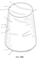
- the shell 12 of the bag 210 in Figures 9-11 has a frusto-conical or tapered shape, and may be formed by multiple panels 20 connected by seams 22 as described herein.
- the shell 12 defines a tapered configuration, having a central body portion 212 formed by a central body panel 214 and circular flat or bulged ends 216, 217 formed by end panels 218, 219.
- the central body portion 212 in Figures 9-11 is formed as a tapered portion and has a frusto-conical shape that has a smaller width, perimeter (e.g., circumference), and cross-sectional area (relative to the central axis of the shell 12) at the bottom 38 and a larger width, perimeter, and cross-sectional area at the top 39, and the central body panel 214 is formed to create this shape.
- the central body portion 212 has a continuous linear taper between the ends 216, 217 when viewed from the side or in cross-section in the embodiment of Figures 9-11 .
- the contour and taper of the central body portion 212 may be different in other embodiments, for example, a concavely curved taper creating a funnel shape, or a convexly curved taper, or a non-continuous linear taper. Additionally, in another embodiment, the central body portion 212 may not be tapered the entire distance between the ends 216, 217, i.e., the tapered portion may be a smaller portion of the central body portion 212. In such a configuration, the central body portion 212 may have a non-tapered portion or a reverse-tapered portion adjacent the tapered portion.
- the ends 216, 217 of the shell 12 in the embodiment of Figures 9-11 are circular in shape, and the end panels 218, 219 forming the ends 216 are circular panels that may be bulged or flat.
- the top end 216 and the top end panel 218 have larger widths, perimeters (e.g., circumferences) and surface areas than the bottom end 217 and the bottom end panel 219, which complements the taper of the central body portion 212.
- the top end 216 may have a width of 30,5-50,8cm, or 35,6-45,7cm ( 12-20 in., or 14-18 in)
- the bottom end 217 may have a width of 15,2-35,6 cm, or 20,3-30,5 cm (6-14 in., or 8-12 in) and the height of the central body portion 212 may be 48.3-63,5 cm, or 50,8-62,2 cm ( 19-25 in., or 20-24.5 in.).
- the bag 210 may be larger or smaller, but the ends 216, 217 may have similar proportions, i.e., the ratio of the width of the top end 216 to the width of the bottom end 217 is 1.25:1 - 2:1 or 1.5:1 - 1.75:1.
- the ratio of the area of the top end 216 to the area of the bottom end 217 is 1.5:1 - 4:1 or 2.25:1 - 3:1
- the taper angle T of the central body portion 212 in such a configuration is 6-10°, or 7-9°, with respect to the vertical direction and/or central axis of the shell 12. It is understood that the central axis is an axis that passes through the center of volume of the shell 12 when fully expanded and passes through the geometric center of the top and bottom ends 216, 217, which may be an axis of symmetry in a symmetrical structure.
- the bag 210 in Figures 9-11 is configured for lifting by the user holding the bag 210 against his/her chest and wrapping his/her arms around the central body portion 212, and the tapering of the central body portion 212 produces a shape that is advantageous for such usage, by aiding the user in holding the bag 210 without downward slippage due to the weight of the bag 210.
- the bag 210 has an opening 24 on the top 38 of the shell 12, which is formed by an opening along the centerline of the top end panel 218 in the embodiment of Figures 9-11 .
- the opening 24 is provided with a closure mechanism 26 in the form of a zipper in this embodiment. It is understood that the opening 24 and the closure mechanism 26 may have any structure discussed herein with respect to the opening 24 and the closure mechanism 26 of Figures 1-8 .
- the opening 24 and the closure mechanism 26 in this embodiment function in the same way as in the bag 10 of Figures 1-8 , whereby the closure mechanism 26 opens to allow the funnel 27 to be extended for filling the bag 210, and the closure mechanism 26 can be closed after collapsing the funnel 27 to seal the opening 24.
- the closure mechanism 26 in Figures 9-11 has a moveable cover 220 that can be moved to cover the opening 24 as shown in Figure 9 , or to uncover the opening 24 as shown in Figure 10 .
- the cover 220 in Figures 9-11 is in the form of a flap that is anchored at a proximal end 221 and has a free distal end 222 that can be folded to cover or uncover the opening 24 as desired.
- the bag 210 in this embodiment has a releasable connecting structure 223 configured for retaining the cover 220 to the top 38 of the shell 12 to cover the opening 24, including complementary engaging members 224, 225 in the form of strips of hook and loop material.
- the releasable connecting structure 223 illustrated in Figure 10 includes engaging members 224 in the form of two strips of hook and loop material connected to the top end panel 218 along opposite sides of the opening 24 and another one or more engaging members 225 in the form of a complementary strip of hook and loop material connected to the underside of the cover 220.
- the bag 210 may be made using the same materials and techniques described herein with respect to the embodiment of Figures 1-8 .
- the shell 12, the inner bag 135, and the filling mechanism 25 can be assembled in a similar manner as the same components in Figures 1-8 .
- Assembly of the bag 210 in Figures 9-11 further includes connecting the engaging members 224 to the top end panel 218 around the opening 24 and connecting the engaging member 225 to the underside of the cover 220, and then connecting the cover 220 to the shell 12, using any of the connection structures and techniques described herein, including stitching, adhesives, and heat sealing, among others.
- Figures 12-18 illustrate an embodiment of a weighted bag 310 of the invention that includes many components and features in common with the bag 10 illustrated in Figures 1-8 and the bag 210 illustrated in Figures 9-11 and described herein.
- Such common features and components are referenced in Figures 12-18 with the same reference numbers used herein with respect to Figures 1-11 , and such common features and components may not be re-described herein in detail with respect to the embodiment of Figures 12-18 .
- the bag 310 of Figures 12-18 includes a filling mechanism 25 that is the same or similar to the filling mechanism 25 described herein and shown in Figures 6-8 , in one embodiment.
- the filling mechanism 25 in this embodiment includes a funnel 27 having all the structural elements described herein with respect to the funnel 27 of Figures 6-8 and functioning in the same manner, but may include additional or alternate features as described herein in other embodiments.
- the bag 310 in Figures 12-18 has a funnel 27 having a flexible encircling wall 160 with a proximal end 161 connected to the inner surface 31 of the shell 12 around the opening 24 and a distal end 162 that can be pulled through the opening 24 to extend the funnel 27 for filling.
- the wall 160 of the funnel 27 in this embodiment defines an inlet 166 proximate the distal end 162 and an exit 164 into the shell 12, and the funnel 27 also has a funnel closure 170 includes a first engaging portion 172 and second engaging portion 174 positioned on opposite sides 165, 167 of the wall 160 at the inlet 166 and securing members 176 as shown in Figures 6-8 and described herein.
- the bag 310 in Figures 12-18 also has an inner bag 135, as shown in Figures 6-8 and described herein, which is also not illustrated in Figures 12-18 . It is understood that the inner bag 135 in the embodiment of Figures 12-18 is shaped to be consistent with the shape of the shell 12 of the bag 210.
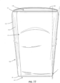
- the shell 12 of the bag 310 in Figures 12-18 has a rectangular shape from the front and the rear and an oval shape (when filled) from the sides.
- the shell 12 defines a rectangular configuration that is elongated between two opposed ends 315.
- the shell 12 has a central body portion 312 formed by a single panel 314 that is wrapped around a top 316 and a bottom 318 of the central body portion 312 and is connected to itself along end seams 313 at opposed ends 315 and along a lateral seam 317 extending between the ends 315 on the rear side 319 of the shell 12.
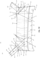
- the rear seam 317 extends across the rear side parallel to the lateral centerline L of the shell 12 (see Figure 13 ) and below the lateral centerline L, i.e., between the lateral centerline L and the bottom 318.
- the shell 12 of the bag 310 in Figures 12-18 is elongated between the ends 315 to form the rectangular shape having four corners 324.
- the corners 324 retain semi-pointed shapes, while the top 316 and bottom 318 become rounded to create the oval shape of the filled shell 12.
- the top 316 and bottom 318 may develop a slight outward curvature toward the corners 324 and a more flattened shape near the lateral centerline of the bag 310.
- the shell 12 may have a different shape in other embodiments, and/or the shell 12 may be made from multiple panels in other embodiments.
- the bag 310 has an opening 24 on the front 320 of the shell 12, which is formed by an opening through the panel 314 along the centerline of the front 320 in the embodiment of Figures 12-18 .
- the opening 24 is provided with a closure mechanism 26 in the form of a zipper in this embodiment. It is understood that the opening 24 and the closure mechanism 26 may have any structure discussed herein with respect to the opening 24 and the closure mechanism 26 of Figures 1-8 .
- the opening 24 and the closure mechanism 26 in this embodiment function in the same way as in the bag 10 of Figures 1-8 , whereby the closure mechanism 26 opens to allow the funnel 27 to be extended for filling the bag 310, and the closure mechanism 26 can be closed after collapsing the funnel 27 to seal the opening 24.
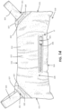
- the closure mechanism 26 in Figures 12-18 has a fixed cover 325 that covers one end of the opening 24 as shown in Figure 14 .
- the cover 325 is positioned so that the handle 326 of the zipper of the closure mechanism 26 can be positioned beneath the cover 325 when the closure mechanism 26 is in the closed position, in order to avoid the zipper handle 326 from pressing into the user's skin during use, enhancing comfort.
- the cover 325 in Figure 14 is in the form of an arch that is anchored at the ends and arches over the end of the opening 24.
- the bag 310 has two handles 321 connected to the shell 12 near the junctures between the top 316 and the ends 315, i.e., the corners 324 along the top 316 of the shell 12 in the rectangular shell 12 shown in Figures 12-18 .
- the handles 321 in this embodiment each include a base 322 fixedly connected to the shell 12 and a gripping member 323 extending outward from the base 322.
- the gripping members 323 are each formed as a loop for the user's hand to extend through in the embodiment of Figures 12-18 .
- each of the gripping members 323 has ends that are connected to the front and rear sides 320, 319 of the shell 12 with the gripping member 323 forming a loop configuration between these connections.
- the gripping members 323 are connected only to the front and rear side 320, 319 of the shell 12 and still have a loop configuration.
- the gripping members 323 extend outward at oblique angles A with the lateral centerline L of the shell 12 (see Figure 13 ) and oblique angles B with the nearest peripheral edges of the shell 12.
- the angles A are approximately 45° (40-50°) to the lateral centerline L
- the angles B are approximately 135° (125-145°) with the nearest peripheral edge, i.e., the top 316 or the nearest end 315 of the shell 12 in this embodiment.
- the angles B are measured with respect to the edges 334 of the gripping members 323 that are nearest the respective peripheral edge of the shell 12.
- the gripping members 323 may extend outward at angles A that are 30-60° to the lateral centerline L of the shell 12), and the edges 334 of the gripping members 323 form angles B of approximately 120-150° with the nearest peripheral edge, i.e., the top 316 or the nearest end 315 of the shell 12 in such embodiments. It is understood that the angles A and B described herein are measured with respect to the gripping members 323 when extended to their furthest degree of extension in their most natural direction of extension, as shown in Figure 13 .
- the angle A measured with respect to the lateral centerline L can be measured with respect to either edge 334 or the geometric centerline GC of the gripping member 323 in an embodiment as in Figure 13 where the edges 334 and the geometric centerline GC are all parallel to each other, although in some less symmetrical configurations, the geometric centerline GC may be a more appropriate.
- the angle A can be measured with respect to at least one of the edges and/or the geometric centerline.
- the angles A and B are measured when the bag 310 is empty and pressed flat to the ground.
- each base 322 of the handles 321 is connected to the shell 12 proximate the top corners 324, and the bases 322 in Figures 12-18 extend on both the front side 320 and the rear side 319 of the shell 12 to permit the gripping members 323 to connect to both sides 319, 320.
- each base 322 is formed of a single strip of material that extends from the nearest end 315 at an angle across the front 320 of the shell 12, over the top 316 of the shell 12, and then at an angle across the rear 319 of the shell 12 back to the end 315. In this configuration, the base 322 is not connected to the corner 324, leaving the corner 324 exposed.
- the base 322 in this configuration has a crossing portion 327 that extends over the top 316 of the shell 12, and the inner edge 328 of the crossing portion 327 (i.e., farthest edge inward from the nearest end 315) in Figures 12-18 extends approximately perpendicular (90°) to the top 316 of the shell 12 when the bag 310 is empty and pressed to the ground.
- the angle C between the inner edge 328 of the crossing portion 327 and the top 316 of the shell 12 is 80-100° or 85-95°.
- the inner edge 328 of the crossing portion 327 may additionally or alternately form the same or similar angles with respect to the lateral centerline L of the shell 12 and/or a line (not shown) extending directly between the top corners 324 on the shell 12.
- the inner edge 328 of the crossing portion 327 is a straight edge in the embodiment of Figures 12-18 , i.e., the inner edge 328 would be straight and linear if the base 322 were laid flat. Additionally, the base 322 in Figures 12-18 has angling portions 329 that angle across the front and rear sides 320, 319 of the shell and juncture with the crossing portion 327, and the inner edge 330 of each angling portion 329 forms a juncture angle D with the crossing portion 327 that is 110-140° or 120-130°.
- the angle E at the juncture between the inner edge 330 of each angling portion 329 and the nearest end 315 of the shell 12 is 40-70° or 50-60°. It is understood that the angles C, D, and E are measured when the bag 310 is empty and pressed flat to the ground.
- the crossing portion 327 in the embodiment of Figures 12-18 has a narrower width measured between the inner edge 328 and the opposite (outer) edge that is smaller than the widths of the angling portions 329.
- Each base 322 may be formed of an integral or continuous panel or strap having first and second opposed surfaces 331, 332, in one embodiment.
- the first surface 331 forms the outer surface of the angling portion 329 on the front side 320 of the shell 12 and the inner surface of the angling portion 329 (contacting the shell 12) on the rear side 319 of the shell 12
- the second surface 332 forms the outer surface of the angling portion 329 on the rear side 319 of the shell 12 and the inner surface of the angling portion 329 (contacting the shell 12) on the front side 320 of the shell 12.
- angles A-E described herein provide a more ergonomic and athletically efficient form for the bag, which is designed to be picked up by a user and thrown over his/her back for carrying so that the top 316 rests on the user's neck and shoulders.
- the angles A-B of the gripping members 323 provide effective and comfortable angles for lifting and carrying, and the angles C-E of the base 322 provide durability and advantageous distribution of forces and stresses on the shell 12 during lifting and carrying.
- the angle C between the inner edge 328 of the crossing portion 327 and the top 316 of the shell 12 avoids excessive concentration of stresses at the juncture between the base 322 and the top 316 of the shell 12, which can result in separation of the base 322 from the shell 12 and/or ripping of the shell 12 at that location. It is also noted that the position of the rear seam 317 below the lateral centerline L of the shell 12 avoids stress concentrations at the seam 317 by distancing the seam 317 from the handles 321 and also reduces the chance that the user will carry the bag 310 with the seam 317 in contact with his/her neck or shoulders, which could reduce comfort.
- the bag 310 may be made using the same materials and techniques described herein with respect to the embodiment of Figures 1-8 .
- the shell 12, the inner bag 135, and the filling mechanism 25 can be assembled in a similar manner as the same components in Figures 1-8 .
- Assembly of the bag 310 in Figures 12-18 further includes connecting the gripping members 323 to the bases 322 of the handles 321, and then connecting the handles 321 to the top side 316 of the shell 12, using any of the connection structures and techniques described herein, including stitching, adhesives, and heat sealing, among others.
- top,” “bottom,” “front,” “back,” “side,” “rear,” “proximal,” “distal,” and the like, as used herein, are intended for illustrative and relative purposes only and do not limit the embodiments in any way. None in this specification should be construed as requiring a specific three dimensional orientation of structures in order to fall within the scope of this invention, unless explicitly specified by the claims. Additionally, the term “plurality,” as used herein, indicates any number greater than one, either disjunctively or conjunctively, as necessary, up to an infinite number. For quantitative values described herein that do not include decimal points, each digit to the left of the decimal point is considered to be a significant digit. The scope of protection of the present invention is only limited by the accompanying claims.
Landscapes
- Health & Medical Sciences (AREA)
- Life Sciences & Earth Sciences (AREA)
- Biophysics (AREA)
- Orthopedic Medicine & Surgery (AREA)
- General Health & Medical Sciences (AREA)
- Physical Education & Sports Medicine (AREA)
- Bag Frames (AREA)
- Purses, Travelling Bags, Baskets, Or Suitcases (AREA)
Description
- The disclosure relates in general to weightlifting devices, and more particularly, to a weighted bag for use in various weightlifting and other exercises.
- The use of different devices in the lifting of weights and general exercising is well known in the art. Many such exercises and lifts generally utilize a rigid or solid weight that is coupled to a handle, a bar or a cable and pulley system. Such devices include lat machines, barbells, kettlebells, dumbbells and the like.
- Increasingly, however, dynamic, or shape changing devices have been utilized. These devices include, but are not limited to shape changing platforms, such as hemispherically shaped structures which are semi-rigid, inflatable structures and the like. Other such devices include balls or bags that can be lifted, carried, thrown or otherwise manipulated.
- Problematically, these non-rigid, flexible devices tend to experience unpredictable forces and non-uniform loading depending on how they are manipulated and/or how they are grasped, dropped or otherwise impacted. At the same time, the material from which such devices are made, by definition, are generally flexible and capable of shape changing. Moreover, where a handle or the like is introduced, the coupling of the handle to the bag is problematic and often a source of deterioration, degradation and failure of the bag. For example openings, tears, rips and the like are often formed proximate the stitching or other joining between the handle and the bag panels, as stress concentrations are experienced in such locations.
- Document
US2012/149536A shows a weighted exercise tubular bag to be filled with e.g. send, and provided with a pair of handles running substantially perpendicular to the length of bag body with grips positioned atop the tubular bag. - The present invention relates to a bag for weightlifting and similar exercises as defined in
claim 1. - Other aspects of the disclosure relate to a bag configured to be filled with a filler material, including a shell having a central body portion that is elongated between opposed first and second ends and has a top and a bottom extending between the first and second ends, where the central body portion and the first and second ends of the shell combine to define and enclose an inner cavity configured for containing the filler material, and where the shell has an opening providing access to the inner cavity and a closure mechanism configured for selectively opening and closing the opening, as well as a handle assembly engaged with the shell. The handle assembly includes a first gripping member connected to the shell proximate a first juncture between the top and the first end and a second gripping member connected to the shell proximate a second juncture between the top and the second end. The first gripping member extends outward from the shell at an oblique angle to at least one of the top, the first end, and the lateral centerline, and the second gripping member extends outward from the shell at an oblique angle to at least one of the top, the second end, and the lateral centerline.
- According to one aspect, the first gripping member includes a first loop having ends connected to front and rear sides of the shell, and the second gripping member includes a second loop having ends connected to the front and rear sides of the shell.
- According to another aspect, the shell is formed of a single panel extending around front and rear sides of the shell and connected to itself by seams at the first and second ends and a lateral seam extending between the first and second ends. In one configuration, the lateral seam extends across the rear side of the shell, and the opening is defined on the front side of the shell.
- According to a further aspect, the handle assembly further includes a first base connected to the shell and extending on the front side and the rear side of the shell and having a first crossing portion extending over the top between the front side and the rear side proximate a first juncture between the top and the first end, and a second base connected to the shell and extending on the front side and the rear side and having a second crossing portion extending over the top between the front side and the rear side proximate a second juncture between the top and the second end. The first gripping member is connected to the first base and extends outward from the first base, and the second gripping member is connected to the second base and extends outward from the second base. In one configuration, the first crossing portion has a first inner edge and the second crossing portion has a second inner edge, and the first and second inner edges each form angles of 80-100° with the top of the shell.
- According to yet another aspect, the shell has a rectangular shape defined by the top, the bottom, and the first and second ends, and/or the shell is configured to have an oval shape when viewed from the first or second end when filled.
- According to a still further aspect, the shell has a length measured between the first and second ends and a height measured between the top and the bottom, and the length is at least two times the height.
- Other aspects of the disclosure relate to a bag configured to be filled with a filler material, including a shell having a front side and a back side and having a central body portion and opposed first and second ends, the central body portion having a top and a bottom extending between the first and second ends, where the central body portion and the first and second ends of the shell combine to define and enclose an inner cavity configured for containing the filler material, and where the shell has an opening providing access to the inner cavity, as well as a handle assembly engaged with the shell. The handle assembly includes a first base connected to the shell and extending on the front side and the rear side and having a first crossing portion extending over the top between the front side and the rear side proximate a first juncture between the top and the first end, a first gripping member connected to the first base and extending outward from the first base, a second base connected to the shell and extending on the front side and the rear side and having a second crossing portion extending over the top between the front side and the rear side proximate a second juncture between the top and the second end, and a second gripping member connected to the second base and extending outward from the second base. The first crossing portion has a first inner edge and the second crossing portion has a second inner edge, and the first and second inner edges each form angles of 80-100° with the top of the shell.
- According to one aspect, the first base further includes a first front angling portion extending on the front side of the shell to the top of the shell at oblique angles to the first end and the top of the shell and a first rear angling portion extending on the rear side of the shell to the top of the shell at oblique angles to the first end and the top of the shell, where the first crossing portion extends between the first front angling portion and the first rear angling portion. In one configuration, the first front angling portion extends on the front side of the shell from the first end to the top of the shell, and the first rear angling portion extends on the rear side of the shell from the first end to the top of the shell. In an additional configuration, the second base further includes a second front angling portion extending on the front side of the shell from the second end to the top of the shell at oblique angles to the second end and the top of the shell and a second rear angling portion extending on the rear side of the shell from the second end to the top of the shell at oblique angles to the second end and the top of the shell, where the second crossing portion extends between the second front angling portion and the second rear angling portion. In a further configuration, the first crossing portion forms juncture angles with the first front angling portion and the first rear angling portion that are 110-140°. In yet another configuration, the first crossing portion has a first width between the first inner edge and a first outer edge of the first crossing portion, and the first front angling portion and the first rear angling portion have widths defined between inner and outer edges thereof, where the first width is smaller than the widths of the first front angling portion and the first rear angling portion. In a still further configuration, the first base is formed of a continuous panel, and the first base is folded over itself at the first crossing portion, such that a first surface of the continuous panel forms an outer surface of the first front angling portion and an inner surface of the first rear angling portion.
- According to another aspect, the shell has a lateral centerline extending between the first and second ends, where the first gripping member extends outward from the first base at an oblique angle to at least one of the top, the first end, and the lateral centerline, and the second gripping member extends outward from the first base at an oblique angle to at least one of the top, the second end, and the lateral centerline.
- According to a further aspect, the first gripping member includes a first loop having ends connected to the first base on the front and rear sides of the shell and the second gripping member includes a second loop having ends connected to the second base on the front and rear sides of the shell.
- According to yet another aspect, the shell is formed of a single panel extending around the front and rear sides and connected to itself by seams at the first and second ends and a lateral seam extending between the first and second ends. In one configuration the lateral seam extends across the rear side of the shell, and the opening is defined on the front side of the shell.
- According to a still further aspect, the shell has a rectangular shape defined by the top, the bottom, and the first and second ends, and/or the shell is configured to have an oval shape when viewed from the first or second end when filled.
- Other features and advantages of the disclosure will be apparent from the following description taken in conjunction with the attached drawings.
- The disclosure will now be described with reference to the drawings wherein:
-
Figure 1 is a front perspective view of one embodiment of a weighted bag which is not part of the present invention; -
Figure 2 is a front elevation view of the weighted bag ofFigure 1 ; -
Figure 3 is a rear elevation view of the weighted bag ofFigure 1 ; -
Figure 4 is a bottom elevation view of the weighted bag ofFigure 1 ; -
Figure 5 is a bottom elevation view of the weighted bag ofFigure 1 ; -
Figure 6 is a cross-section view of the weighted bag ofFigure 1 taken along a central plane, with a filling mechanism in the form of a funnel extended from the weighted bag and a filling material filling the weighted bag; -
Figure 7 is a cross-section view of the weighted bag ofFigure 6 , with the funnel in a partially-collapsed configuration; -
Figure 8 is a cross-section view of the weighted bag ofFigure 6 , with the funnel in a fully collapsed configuration; -
Figure 9 is a front perspective view of another embodiment of a weighted bag which is not part of the present invention; -
Figure 10 is a front perspective view of the weighted bag ofFigure 9 , with a releasable cover of the bag moved to expose an opening of the bag; -
Figure 10A is a bottom front perspective view of the weighted bag ofFigure 9 ; -
Figure 11 is a front elevation view of the weighted bag ofFigure 9 ; -
Figure 12 is a rear perspective view of a weighted bag according to aspects of the present invention; -
Figure 13 is a rear elevation view of the weighted bag ofFigure 12 ; -
Figure 14 is a front elevation view of the weighted bag ofFigure 12 ; -
Figure 15 is a right side elevation view of the weighted bag ofFigure 12 ; -
Figure 16 is a left side elevation view of the weighted bag ofFigure 12 ; -
Figure 17 is a magnified view of a portion of the weighted bag ofFigure 13 ; and -
Figure 18 is a magnified view of a portion of the weighted bag ofFigure 14 . - It will be understood that like or analogous elements and/or components, referred to herein, may be identified throughout the drawings by like reference characters. In addition, it will be understood that the drawings are merely schematic representations of the invention, and some of the components may have been distorted from actual scale for purposes of pictorial clarity.
- Referring now to the drawings and in particular to
Figures 1-8 , a weighted bag with a handle for weightlifting is shown generally atreference number 10. Theweighted bag 10 includes anouter shell 12 and handleassembly 14. Thehandle assembly 14 is coupled to theouter shell 12 by two or more points along theweighted bag 10, such as by astrap assembly 70 as described herein. Theweighted bag 10 as shown inFigures 1-8 is configured for weightlifting and similar exercises, and can be lifted, carried, thrown, dropped, and otherwise used to enhance strength, agility and the like. - The
outer shell 12, shown inFigures 1-8 , comprises one ormore panels 20 that are connected by one ormore seams 22, anopening 24 with ashell closure member 26. Each of thepanels 20 has aninner surface 31 defining aninner cavity 21 configured to hold afiller material 16 and anouter surface 32 opposite theinner surface 31. Theshell 12 has a top 38 and a bottom 39, such that theopening 24 is positioned on the top 38, and thebag 10 is configured to rest on the bottom 39. It is understood that the top 38 and the bottom 39 are relative terms that depend on the orientation of thebag 10. - It is to be understood the
inner surface 31 andouter surface 32 of thepanels 20 may be defined by one or more surfacing layers that may be of substantially equal or variable materials. Generally, these are two or greater ply configuration coupled together. In the configuration shown, the panels are shown as singular pieces with the understanding that they may represent multiple plies of material. In one embodiment, thepanels 20 are formed from a two ply construction, with the outer and inner plies comprising different grades of ballistic nylon fabric (the outside being of 1000 denier and the inside being of 500 denier). Of course, other configurations are contemplated. - With reference to the example embodiment of the
outer shell 12 inFigures 1-8 , thepanels 20 include at least twoopposed end panels 50 andcentral body panel 58. Eachend panel 50 has anouter panel 51, aninner panel 52, and slot 57 defined between the inner andouter panels outer panel 51 is coupled to theinner panel 52 by any number of different structures, but not limited to, cross- stitching, heat sealing, adhesive, among others. Eachslot 57 in this embodiment, as shown inFigures 6-8 , extends between the outer andinner panels lower openings 53 to permit passage into and out of theslot 57, and theslot 57 extends continuously between theopenings 53. In one embodiment, as shown inFigures 1-5 , the outer andinner panels panels panels slot 57 that is narrower than the widths of thepanels Figures 1-8 , theend panels 50 are substantially parallel with each other, and thecentral body panel 58 extends between theend panels 50. Theshell 12 in the embodiment ofFigures 1-8 is entirely or substantially defined by theend panels 50 and thecentral body panel 58. In this embodiment, theshell 12 defines a cylindrical configuration, having a circular cylindrical portion orcentral body portion 54 formed by thecentral body panel 58 and circular flat or bulged ends 55 formed by theend panels 50. In other embodiments, theshell 12 may have a different shape, such as an oval cylinder, a cube, a rectangular cylinder, a triangular cylinder, etc. It is understood that thecylindrical portion 54 may simply be referred to as a "central body portion" when describing ashell 12 having a cylindrical shape or any other shape. Likewise, the relative sizes and shapes of theend panels 50 and thecentral body panel 58 may be different in other embodiments, and thecylindrical portion 54 and/or theends 55 may be formed of a greater of smaller number of panels in other embodiments. In general, thecylindrical portion 54 and theends 55 may each be formed by one ormore panels 22. - In the embodiment of
Figures 1-8 , thebag 10 has anopening 24 and afilling mechanism 25 that is accessible through theopening 24 for filling thebag 10. Theopening 24 in the embodiment ofFigures 1-8 is placed along thecentral body panel 58 in such a manner that it allows entry to theinner cavity 21 of thebag 10. Theopening 24 shown inFigures 1 and5 is oriented along the length ofcentral body panel 58 at the top of thebag 10, but theopening 24 may be oriented and/or located differently in other embodiments. Theopening 24 includes a closure member 26 (also called a shell closure member) configured for releasably closing theopening 24. When engaged, theshell closure member 26 resists the movement offiller material 16 into or out of theopening 24. In the configuration shown, theopening 24 and theshell closure member 26 are positioned directly below the natural position of thehandle 60, which can reduce the stresses that are placed in the region surrounding the opening. - As shown in
Figures 1 and5-8 , theopening 24 is defined byfirst side edge 140,second side edge 142,first end 144, andsecond end 146 which collectively define the perimeter of the opening. Thefirst side edge 140 andsecond side edge 142 are opposite and substantially parallel to each other and separated by the width of theopening 24. Further, thefirst end 144 andsecond end 146 are opposite to each other and separated by the length of theopening 24. Thefirst side edge 140 andsecond side edge 142 are connected at their respective ends byfirst end 144 andsecond end 146. The first and second ends 144, 146 may be formed as V-shaped or U-shaped structures in one embodiment or may be straight linear sides that are substantially parallel to each other and perpendicular to the side edges 140, 142 in another embodiment. Generally, theopening 24 has an elongated rectangular configuration in the embodiment ofFigures 1-8 , and theopening 24 may have a differently-shaped configuration in other embodiments. - The
shell closure member 26 is substantially planar to theopening 24 and coupled in such a way to edges of opening 24 that closure of theshell closure member 26 substantially closes theopening 24. Theshell closure member 26, in the configuration ofFigures 1-8 , includes a zipper. In this configuration, the dimensions of theopening 24 are similar to the size of theshell closure member 26. In other words, the lengths of the edges of theshell closure member 26 are substantially parallel and comparable to thefirst side edge 140 andsecond side edge 142 of theopening 24. In contemplated configurations, theshell closure member 26 is secured in a manner that ensures close coupling along theentire edges opening 24. In other embodiments, theshell closure member 26 may have other configurations, such as a hook and loop fastener, snaps, buttons, flaps, and other fastening and/or closing structures or combinations of such structures may be utilized. It is understood that the configuration of theshell closure member 26 may depend at least partially on the configuration of theopening 24. For example, ashell closure member 26 in the form of a zipper may not be usable or optimal with someopening 24 configurations, and another type ofclosure member 26 may be used. - In the embodiment of
Figures 1-8 , thefilling mechanism 25 includes afunnel structure 27 having a flexibleencircling wall 160 forming a funnel shape, a grasping handle or graspingmember 168, a fillingmechanism closure member 170, and securingmember 176. With particular reference toFigures 6-8 , the flexibleencircling wall 160 has aproximal end 161, adistal end 162, alower exit 164, and anupper inlet 166. Theproximal end 161 anddistal end 162 are on opposite ends of thefunnel 27, and theproximal end 161 is a fixed end connected to theshell 12, while thedistal end 162 is a free end that can be extended out of theshell 12 through theopening 24 or retracted into theshell 12. - The
proximal end 161 is connected to the inner surface 130 of theouter shell 12, as shown inFigures 6-8 , and the connection between theproximal end 161 and theshell 12 forms a lower perimeter of thefunnel 27. In the configuration ofFigures 6-8 , theproximal end 161 of thefunnel 27 is secured to the inner surface of theshell 12 around theentire opening 24, along a connection line spaced from theopening 24. This configuration resists leakage of thefiller material 16 through the connection between theproximal end 161 and theshell 12 and also provides apocket 17 inside theopening 24 where thefunnel 27 can be placed after collapsing, e.g., by folding or rolling, as described herein. Thedistal end 162, when fully extended and expanded, forms an upper perimeter of the funnel, and it is understood that the upper perimeter may be larger than the lower perimeter in one embodiment. Further, thefunnel 27 may have a neck ornarrowest portion 163 that is located between the proximal anddistal ends distal ends Figures 6-8 , theneck 163 is located closer to theproximal end 161 than thedistal end 162 and is configured to be generally located within theopening 24 when thefunnel 27 is fully extended and expanded. It is to be understood the actual circumference or width at some locations are subject to change in shape, size and/or width during operation, articulation and folding of thefunnel 27, and that the relative circumferences and widths described herein are the maximum such dimensions when thefunnel 27 is fully extended and expanded. Thewall 160 inFigures 6-8 , including thelower exit 164 and theupper inlet 166, may be substantially oval or rectangular in shape in one embodiment, but these components are subject to variable changes in length and width in contemplated configurations and desired sizes of theweighted bag 10. It is to be understood the openings (exit 164 and inlet 166) are substantially large enough to allow entry of physical materials, such as sand or polymer beads, with minimal interference or resistance from the fillingmechanisms 25. - The
funnel 27 may have one or moregrasping handles 168 at or near thedistal end 162 to assist in pulling thefunnel 27 through theopening 24 and/or opening thefunnel closure 170 as described herein. Thefunnel 27 inFigures 6-8 has twograsping handles 168 on opposite sides of theinlet 166, with eachgrasping handle 168 in the form of a thin strap connected to the exterior of thewall 160 of thefunnel 27. The grasping handles 168 are oriented to extend outwardly from thedistal end 162 when thefunnel 27 is in an open and extended position. Placement of the graspinghandle 168 on the funnel is variable and subject to change in contemplated configurations of thefunnel 27. The graspinghandle 168 may be connected to thewall 160 by stitching, adhesive, or heat sealing, among other techniques, or a combination of such techniques. - The
funnel 27 also has afunnel closure 170 configured to close theinlet 166 to resist egress of theparticulate material 16. In the embodiment ofFigures 6-8 , thefunnel closure 170 includes a firstengaging portion 172 and second engagingportion 174 positioned onopposite sides wall 160 at theinlet 166 proximate thedistal end 162 and configured to engage each other to releasably close theinlet 166. The firstengaging portion 172 and second engagingportion 174 include elongated strips of complementary hook and loop materials that releasably connect to each other when engaged. The engagingportions sides upper inlet 166 and resist the entry or exit of material through theupper inlet 166. In the embodiment ofFigures 6-8 , the strips forming the first and second engagingportions inlet 166 to completely close theinlet 166 when engaged. In other embodiments, other releasable connecting or fastening structures can be used as thefunnel closure 170, such as snaps, buttons, zippers, and the like, as well as complementary structures when appropriate, or combinations of different structures. - The
funnel 27 also includes afunnel securing structure 176 configured to secure and further resist ingress or egress of material through thefunnel 27. Thefunnel securing structure 176 inFigures 6-8 includes a first securingmember 177 and asecond securing member 178 that are configured to engage each other to releasably close theinlet 166. Thefunnel securing structure 176 inFigures 6-8 is lower on the flexibleencircling wall 160 than thefunnel closure 170. The securingmembers encircling wall 160 onopposite sides wall 160 at different distances from thedistal end 162. Thefirst securing member 177 is connected to thefirst side 165 closer to thedistal end 162, and the second securingmember 178 is connected to thesecond side 167 farther from thedistal end 162. In this configuration, thewall 160 is configured to be rolled or folded by rolling or folding thefirst side 165 over thesecond side 167 as shown inFigure 8 to achieve engagement of the securingmembers funnel 27 in the rolled or folded position. The securingmembers members structure 176 may have a different configuration in other embodiments, such as any configuration of thefunnel closure 170 discussed herein. - The
inner cavity 21 of theouter shell 12 hasfiller material 16 within it when the device is prepared for use.Filler material 16 is designed to be a heavy but loose and flowable material including, but not limited to, sand, polymer beads, or other such particulate materials. In the embodiment ofFigures 1-8 , thebag 10 has aninner bag 135 connected around theopening 24 to contain thefiller material 16, with seams (not shown) that define the shape of theinner bag 135 and/or connect pieces forming theinner bag 135. Theinner bag 135 has anopen end 136 that is connected to theshell 12 around theopening 24 such that theinner bag 135 is in communication with theexit 164 of thefunnel 27. In this configuration,filler 16 fed into theinner cavity 21 through thefilling mechanism 25 enters theinner bag 135 and is held by theinner bag 135. Theinner bag 135 and theshell 12 may be designed differently in materials, connections (e.g., seams 22), and structure. For example, the materials, connections, and structure of theshell 12 may be configured for strength, durability, abrasion resistance, and comfort in handling, while the materials, connections, and structure of theinner bag 135 may be configured primarily for strength and resisting leakage. - The
bag 10 can be filled by opening theshell closure member 26 to open theopening 24 and extending thefilling mechanism 25 through theopening 24. Thefunnel 27 inFigures 6-8 can be fully extended by pulling thefunnel 27 through the opening, disconnecting the securingstructure 176, and then fully extending thefunnel 27. When fully extended, thefunnel 27 can be opened by disconnecting theclosure 170 to open theinlet 166, which may be done with the assistance of the grasping handles 168. It is noted that the grasping handles may also be used to hold theupper inlet 166 open during filling. Once open, thefiller material 16 can be filled into the cavity 21 (and theinner bag 135 if present) by entering through theupper inlet 166, travelling through thefunnel 27, and exiting into thebag 10 through thelower exit 164. - After the desired amount of
filler material 16 has been fed into theinner cavity 21 of theweighted bag 10, theclosure 170 of thefilling mechanism 25 is manipulated to close theinlet 166. In the embodiment ofFigures 6-8 , the first and second engagingportions inlet 166 of thefunnel 27. Thefilling mechanism 25 can also then be collapsed into theopening 24, using the securingstructure 176 to further secure thecollapsed filling mechanism 25. In the embodiment ofFigures 6-8 , thefunnel 27 is collapsed by rolling or folding the top of the flexibleencircling wall 160 at such amounts and to such a degree to cause the securingmembers funnel 27 in a collapsed position. Thefilling mechanism 25 can then be pushed throughopening 24 and into thecavity 21 of theshell 12, and theshell closure member 26 is then manipulated to close theopening 24. In this collapsed configuration, thefunnel 27 is received within apocket 17 defined below theopening 24 between theproximal end 161 of thefunnel 27 and theinner surface 31 of theshell 12. The resultant configuration of thefilling mechanism 25 is sealed against ingress and egress of material in multiple ways, including by theshell closure member 26, thefilling mechanism closure 170, and the folding or rolling of the filling mechanism 25 (secured by the securing structure 176), which creates a tortuous path for the fillingmaterial 16 to escape. - The
handle assembly 14 of thebag 10 inFigures 1-8 includes ahandle 60 and astrap assembly 70 including one or more straps connecting thehandle 60 to theshell 12 to permit thebag 10 to be lifted by grasping thehandle 60. In one embodiment where theshell 12 has a cylindrical shape, such as shown inFigures 1-8 , thestrap assembly 70 includes at least onecircumferential strap 71 that extends partially or completely around the circumference of thecylindrical portion 54 of theshell 12. Thestrap assembly 70 inFigures 1-8 includes first and second circumferential orperipheral straps 71 extending around at least a portion of the periphery of theshell 12, and a central ortransverse strap 80 extending around at least a portion of the periphery of theshell 12 transverse to the circumferential straps 71. The circumferential straps 71 as shown inFigures 1-5 extend parallel to each other around thecylindrical portion 54 of theshell 12, with the twocircumferential straps 71 each located proximate one of theends 55, and thecentral strap 80 extends around thecylindrical portion 54 and the circular ends 55 of theshell 12 perpendicular or transverse to both circumferential straps 71. It is noted that the term "circumferential" is used herein with respect to a circular cylindrical structure as shown inFigures 1-8 , but that the term "peripheral" may be used to describe these straps for use with a structure that is not necessarily circular. The terms "circumferential" and "peripheral" as used herein are not intended to imply that the relevant strap necessarily extends around the entire circumference or periphery of thebag 10, but only specify the direction in which the strap extends, i.e., around the circumference or periphery. - In the embodiment of
Figures 1-5 , the first and secondcircumferential straps 71 extend from opposite ends 66 of thehandle 60 circumferentially around the periphery of thecylindrical portion 54, around the bottom 39 of theshell 12, and back toward the top 38 of theshell 12 to engage thehandle 60. The firstcircumferential strap 71 in this embodiment includes afirst strap portion 74 that engages thehandle 60 at oneend 66 and extends in a first circumferential direction around a portion of thecylindrical portion 54 of theshell 12 and asecond strap portion 75 that engages thehandle 60 at oneend 66 and extends in a second, opposite circumferential direction around a portion of thecylindrical portion 54 of theshell 12. Thestrap portions circumferential strap 71 are joined together at a joint 76 on the bottom 39 of theshell 12 to form asingle strap 71. In other embodiments, thestrap portions continuous strap 71, or may not connect together, e.g., such as by connecting to theshell 12. The secondcircumferential strap 71 inFigures 1-5 is similarly configured, including afirst strap portion 77 that engages thehandle 60 at oneend 66 and extends in a first circumferential direction around a portion of thecylindrical portion 54 of theshell 12 and asecond strap portion 78 that engages thehandle 60 at oneend 66 and extends in a second, opposite circumferential direction around a portion of thecylindrical portion 54 of theshell 12. Thestrap portions circumferential strap 71 are joined together at a joint 79 on the bottom 39 of theshell 12 to form asingle strap 71. In other embodiments, thestrap portions continuous strap 71, or may not connect together, e.g., such as by connecting to theshell 12. Thejoints - In the embodiment of
Figures 1-5 , thefirst strap portions circumferential straps 71 are formed as an integral orcontinuous strap 72 that extends from the joint 76 into and through thehandle 60 and to the other joint 79, and thesecond strap portions circumferential straps 71 are similarly formed as an integral orcontinuous strap 73. In this embodiment, the first and second circumferential straps are all formed as part of a continuous strap, connected by thejoints straps cylindrical portion 54 proximate opposite ends 55 in this embodiment, but it is understood that in another embodiment thestraps handle 60 and extend on opposite sides. Thestrap portions handle 60 at least by extending through thehandle 60, and may be fixedly connected to thehandle 60, or thehandle 60 may be able to slide with respect to thestrap portions strap portions handle 60, or eachcircumferential strap 71 may itself be formed as a single piece engaged with thehandle 60. In a further embodiment, both of thecircumferential straps 71 may be formed by a single-piece strap that extends twice through thehandle 60 and around both ends of thecylindrical portion 54 of theshell 12. It is understood that the engagement between thestrap portions handle 60 and theshell 12 is sufficient that theshell 12 can be lifted by exerting an upward force on thehandle 60. - In the embodiment of
Figures 1-5 , thecircumferential straps 71 are connected to or engaged with theshell 12 in a slidable configuration by retainingstructures 28 in the form of loop assemblies or belt loop assemblies, rather than being fixedly connected to theshell 12. It is understood that the retainingstructures 28 may be referred to asloop assemblies 28 in discussing the embodiment ofFigures 1-5 herein, but that other retaining structures may be used to achieve similar functionality. In another embodiment, one or both of thecircumferential straps 71 may be provided in the same or a similar configuration while being fixedly connected to theshell 12, such as by stitching, adhesive, heat sealing, etc. Theloop assemblies 28 inFigures 1-5 are positioned around thecylindrical portion 54 of theshell 12 at or proximate to the opposed ends 55, and may be referred to as a firstend loop assembly 28 and a secondend loop assembly 28. In the embodiment ofFigures 1-5 , the firstend loop assembly 28 secures the firstcircumferential strap 71 to theshell 12, and the secondend loop assembly 28 secures the secondcircumferential strap 71 to theshell 12. Theloop assemblies 28 in this configuration extend in both circumferential directions around thecylindrical portion 54 of theshell 12, from the top 38 to the bottom 39 of theshell 12. - The
shell 12 inFigures 1-5 also hascircumferential supports 30 that are fixedly connected to the shell 12 (e.g., to the central body panel 58) circumferentially around thecylindrical portion 54 proximate theends 55 and extend beneath theloop assemblies 28. The circumferential supports 30 in the embodiment ofFigures 1-5 are connected to theshell 12 around the entire circumference of theshell 12 and across the entire width of eachsupport 30, except for the locations where the circumferential supports 30 cross theopening 24 and theclosure 26, where the circumferential supports 30 are connected only around the outer edge (the junctures with the end panels 50). The circumferential supports 30 may be made from woven nylon or other durable fabric material and may be connected to theshell 12 by stitching and adhesives in one embodiment, but may be differently configured in other embodiments. - The
loop assemblies 28 in the embodiment ofFigures 1-5 each include a plurality of cross supports 33 that define achannel 35 beneath the cross supports 33, such that the cross supports 33 extend across thechannel 35. The cross supports 33 inFigures 1-5 are arranged in an alternating or oscillating pattern, where eachcross support 33 is oriented at an oblique angle to the circumferential direction, the longitudinal direction (i.e., between the ends 55), thechannels 35, thecircumferential straps 71, and theseams 22 around the end panels 50 (e.g., a "zig-zag" pattern). In this configuration, adjacent cross supports 33 havetriangular gaps 37 between them to expose portions of thecircumferential straps 71 beneath. In one configuration, the end of eachcross support 33 overlaps with the end(s) of the adjacent cross support(s) 33 as shown inFigures 1-5 , and these overlapping portions of the cross supports 33 are stitched together at the points of connection between the cross supports 33 and theshell 12. These points of connection may be formed by continuouscircumferential seams 29 that are spaced from each other, parallel to each other, and located on opposite sides of therespective channel 35, as shown inFigures 1-5 . In one embodiment, the cross supports 33 form angles of 55-60° or 50-65° with the edges of the circumferential supports and/or the circumferential direction, and adjacent cross supports 33 are oriented at angles of 60-70° with each other, although other angular orientations may be used in other embodiments. - Each
channel 35 in the embodiment ofFigures 1-5 is defined by a single strip of material that is folded over itself to form an overlapping, alternating pattern and stitched at and around the folds to theshell 12 to form the cross supports 33. In another embodiment, the cross supports 33 defining eachchannel 35 may be separate pieces that are connected together. The cross supports 33 in the embodiment ofFigures 1-5 are connected directly to the circumferential supports 30, but this configuration may vary. In this configuration, thecircumferential straps 71 are slidably restrained between theloop assemblies 28 and the circumferential supports 30, and the circumferential supports 30 provide strength, durability, and abrasion resistance at these areas. Thechannels 35 are defined between the undersides of the cross supports 33 and the confronting surface of theshell 12, which may include the circumferential supports 30 as in the embodiment ofFigures 1-5 , or theouter surface 32 of theshell 12 or other structures in other configurations. Additionally, in one embodiment, the cross supports 33 are connected to the circumferential supports 30, and both such structures are connected to theshell 12, by two parallel, spaced circumferential seams 29. In the embodiment ofFigures 1-8 , one of suchcircumferential seams 29 also forms the connection between the outer andinner end panels center body panel 58. In another embodiment, where acircumferential support 30 or other support layer is not present, the cross supports 33 may be directly connected to theshell 12 along suchcircumferential seams 29. - The
channels 35 of each of theloop assemblies 28 inFigures 1-5 include anentrance region 34 at or near the top 38 of thebag 10, and anexit region 36 at or near the bottom 39 of thebag 10. In this configuration, thecircumferential straps 71 extend through thechannels 35, such that each of thestrap portions entrance region 34 of one of thechannels 35, through therespective channel 35, and out theexit region 36 of thechannel 35. Thejoints circumferential straps 71 are located in the spaces between theexit regions 36 of the twochannels 35 of therespective loop assembly 28. In another embodiment, the retainingstructures 28 may not be in the form of loop assemblies with cross supports 33, and may instead use solid or porous panels to create thechannels 35, similar to theslots 57, or may use a different structure for retaining the circumferential straps 71. It is understood that the retaining structures orloop assemblies 28 and associated structures such as the circumferential supports 30 are not illustrated inFigures 6-8 for simplification purposes. - The strapping
assembly 70 also includes a central strap ortransverse strap 80 that extends in a peripheral direction from thehandle 60 around both ends 55 of theshell 12. Thecentral strap 80 includes first and secondcentral strap portions handle 60 and extend from theends 66 of thehandle 60 around opposite ends 55 of theshell 12, and thestrap portions central strap 80 are joined together at a joint 83 on the bottom 39 of theshell 12 to form asingle strap 80. In the embodiment ofFigures 1-8 , thecentral strap 80 is formed as a single piece, extending through thehandle 60 to form thestrap portions handle 60 and having two ends that meet at the joint 83. In another embodiment, thecentral strap portions handle 60. The joint 83 is formed by a combination of stitching and adhesives in one embodiment, but may be formed by additional connecting structures and techniques described herein, or combinations thereof. In another embodiment, thecentral strap portions shell 12 on theends 55 or on the bottom 39. It is understood that the engagement between thestrap portions handle 60 and theshell 12 is sufficient that theshell 12 can be lifted by exerting an upward force on thehandle 60. - The
portions central strap 80 inFigures 1-8 extend around theends 55 of theshell 12 by extending through theslots 57 in the ends 55. As shown inFigures 6-8 , thecentral strap portions inner panels lower openings 53 to pass into and out of theslot 57. Thecentral strap portions circumferential straps 71 and across the bottom 39 of theshell 12 in this embodiment. Thecentral strap 80 is slidably received within theslots 57 and is not fixedly connected to theshell 12 in the embodiment ofFigures 1-8 , but one or both of thecentral strap portions shell 12, e.g., within theslot 57 or on the bottom 39 of theshell 12. In another embodiment, thestrap portions ends 55 of theshell 12 by extending on the outsides of theouter panels 51. Theinner panels 52 and/or theslots 57 may be absent, or theslots 57 may be created by an external structure, in such a configuration. - The
strap assembly 70 in the embodiment ofFigures 1-8 assists with distribution of forces around theshell 12, allowing thebag 10 to be handled roughly and even thrown into the air (e.g., 4,6 m (15 feet) or more) and landing on the ground, while containing heavy filler material 16 (e.g., 22,7-45,3 kg (50-100 pounds)). The positions and orientations of thestraps handle 60 evenly around theshell 12 and avoid concentration of stresses that can result at seams, bonds, or other fixed connections. Additionally, the ability of thestraps shell 12 allows more even exertion of forces on thestraps strap other straps strap assembly 70 further improves durability of thestraps bag 10 as a whole, among other benefits. - The
handle 60 in the embodiment ofFigures 1-8 is formed as an elongatedtubular body 62 having a circular cross section and a central bore orpassage 64 extending between opposing ends 66 along the direction of elongation. Thebody 62 is also slightly curved or arcuate in this configuration, rising in the middle with respect to the ends 66. In this embodiment, thehandle 60 is oriented to extend longitudinally with respect to theshell 12, i.e., between theends 55 and parallel to the central axis of thecylindrical portion 54. The outer surface of thebody 62 of thehandle 60 forms a grasping surface configured to be grasped by the user, and a coating, sleeve, or other structure applied to thebody 62 to enhance gripping. Thehandle 60 may also have a coating, sleeve, or other structure applied to the inside of thecentral passage 64 to either increase or decrease grip or friction with respect to thestraps central passage 64. In one embodiment, thehandle 60 and/or thebody 62 thereof may be made from a flexible and resilient material, such as a PVC hose material or the like. In the embodiment ofFigures 1-8 , thehandle 60 is positioned above theouter shell 12 and theopening 24. In other embodiments, thehandle 60 may have a different structure or material construction, including different shapes including, but are not limited to, ovals, squares, rectangles, or other shapes. In another embodiment, thehandle 60 may not have acentral passage 64, such as in an embodiment where thestraps handle 60 has other structures for engagingcontinuous straps handle 60 may have structures for fixedly connecting to thestraps - One embodiment of a method for assembly of a
weighted bag 10 as shown inFigures 1-8 may be performed using stitching, adhesives, heat sealing or pressing, or various other connection techniques to form seams and other connections between the various components. Theloop assemblies 28 in this embodiment are constructed by folding four strips of material to form the cross supports 33 and fixedly connecting the cross supports 33 (e.g., by stitching, adhesives, heat sealing, etc.) along the edges of the circumferential supports 30 to create the alternating configuration of the cross supports 33. The cross supports 33 are not connected along the middle of the circumferential supports 30 to define thechannels 35 between the cross supports 33 and the circumferential supports 30. The circumferential straps 71 and thecentral strap 80 are connected to thehandle 60, which is accomplished in the embodiment ofFigures 1-8 by pulling and/or pushing the single-piece straps 72, 73, 80 through thecentral passage 64 of thehandle 60, such that thestraps straps handle 60 in one embodiment. - The
funnel 27 is assembled by creating theencircling wall 160, e.g., from a single piece of fabric wrapped and connected to itself to form a funnel structure. The engagingportions members wall 160 in appropriate locations, in the form of complementary strips of hook and loop material, in the embodiment ofFigures 1-8 . The grasping handles 168 may also be connected to thewall 160 at or proximate theinlet 166, and in one embodiment, the graspinghandles 168 are connected prior to the engagingportions portions portions 168. - The
central body panel 58 is prepared by cutting theopening 24 through thecentral body panel 58 and theshell closure member 26 is connected to theopening 24. Theshell closure member 26 may be provided with a shroud or other cover to protect theshell closure member 26 and increase comfort if theshell closure member 26 is contacted by the user during use, including a moveable cover or a static cover, e.g., to cover rigid surfaces such as zipper teeth. The circumferential supports 30 and theloop assemblies 28 are then positioned over and connected to theouter surface 32 of thecentral body panel 58 along opposite edges of thecentral body panel 58. Theinner bag 135 is connected to thecentral body panel 58 by connecting theopen end 136 around theopening 24 on theinner surface 31. Theinner bag 135 may be formed before connecting to thecentral body panel 58, such as by connecting several panels of material together or using seams to form a single piece of material in the correct shape for theinner bag 135. Thefunnel 27 is also connected to thecentral body panel 58. by connecting theproximal end 161 of thewall 160 around theopening 24 on theinner surface 31. In one embodiment, thefunnel 27 and theinner bag 135 may be connected together to thecentral body panel 58. - The
shell 12 is then completed by connecting theend panels 50 to thecentral body panel 58 around theseams 22 shaped to form thecylindrical portion 54 with circular ends 55. In one embodiment, theinner panels 52 and theouter panels 51 are connected to thecentral body panel 58 with thesame seam 22 or connection, and in another embodiment, theinner panels 52 are connected before theouter panels 51. Theinner panels 52 are connected around their entire perimeters in this configuration, and theouter panels 51 are connected around the majority of the perimeters, but are not connected in strategic areas to form theslots 57. It is understand that a cover or lining may be applied around theopenings 53 of eachslot 57 for durability and abrasion resistance. Thehandle assembly 14 is then coupled to theshell 12 by extending thecircumferential strap portions channels 35 and joining them at thejoints circumferential straps 71, and extending thecentral strap portions slots 57, and then joining them at the joint 83 to form thecentral strap 80. Thebag 10 ofFigures 1-8 is substantially complete after these steps have been accomplished. -
Figures 9-11 illustrate another embodiment of aweighted bag 210 that includes many components and features in common with thebag 10 illustrated inFigures 1-8 and described herein. Such common features and components are referenced inFigures 9-11 with the same reference numbers used herein with respect toFigures 1-8 , and such common features and components may not be re-described herein in detail with respect to the embodiment ofFigures 9-11 . While not illustrated in the drawings, thebag 210 ofFigures 9-11 includes afilling mechanism 25 that is the same or similar to thefilling mechanism 25 described herein and shown inFigures 6-8 , in one embodiment. Thefilling mechanism 25 in this embodiment includes afunnel 27 having all the structural elements described herein with respect to thefunnel 27 ofFigures 6-8 and functioning in the same manner, but may include additional or alternate features as described herein in other embodiments. For example, thebag 210 inFigures 9-11 has afunnel 27 having a flexibleencircling wall 160 with aproximal end 161 connected to theinner surface 31 of theshell 12 around theopening 24 and adistal end 162 that can be pulled through theopening 24 to extend thefunnel 27 for filling. Thewall 160 of thefunnel 27 in this embodiment defines aninlet 166 proximate thedistal end 162 and anexit 164 into theshell 12, and thefunnel 27 also has afunnel closure 170 includes a firstengaging portion 172 and second engagingportion 174 positioned onopposite sides wall 160 at theinlet 166 and securingmembers 176 as shown inFigures 6-8 and described herein. Thebag 210 inFigures 9-11 also has aninner bag 135, as shown inFigures 6-8 and described herein, which is also not illustrated inFigures 9-11 . It is understood that theinner bag 135 in the embodiment ofFigures 9-11 is shaped to be consistent with the shape of theshell 12 of thebag 210. - The
shell 12 of thebag 210 inFigures 9-11 has a frusto-conical or tapered shape, and may be formed bymultiple panels 20 connected byseams 22 as described herein. In this embodiment, theshell 12 defines a tapered configuration, having acentral body portion 212 formed by acentral body panel 214 and circular flat or bulged ends 216, 217 formed byend panels central body portion 212 inFigures 9-11 is formed as a tapered portion and has a frusto-conical shape that has a smaller width, perimeter (e.g., circumference), and cross-sectional area (relative to the central axis of the shell 12) at the bottom 38 and a larger width, perimeter, and cross-sectional area at the top 39, and thecentral body panel 214 is formed to create this shape. Thecentral body portion 212 has a continuous linear taper between theends Figures 9-11 . The contour and taper of thecentral body portion 212 may be different in other embodiments, for example, a concavely curved taper creating a funnel shape, or a convexly curved taper, or a non-continuous linear taper. Additionally, in another embodiment, thecentral body portion 212 may not be tapered the entire distance between theends central body portion 212. In such a configuration, thecentral body portion 212 may have a non-tapered portion or a reverse-tapered portion adjacent the tapered portion. - The ends 216, 217 of the
shell 12 in the embodiment ofFigures 9-11 are circular in shape, and theend panels ends 216 are circular panels that may be bulged or flat. Thetop end 216 and thetop end panel 218 have larger widths, perimeters (e.g., circumferences) and surface areas than thebottom end 217 and thebottom end panel 219, which complements the taper of thecentral body portion 212. In one embodiment, thetop end 216 may have a width of 30,5-50,8cm, or 35,6-45,7cm ( 12-20 in., or 14-18 in), thebottom end 217 may have a width of 15,2-35,6 cm, or 20,3-30,5 cm (6-14 in., or 8-12 in) and the height of thecentral body portion 212 may be 48.3-63,5 cm, or 50,8-62,2 cm ( 19-25 in., or 20-24.5 in.). In another embodiment, thebag 210 may be larger or smaller, but the ends 216, 217 may have similar proportions, i.e., the ratio of the width of thetop end 216 to the width of thebottom end 217 is 1.25:1 - 2:1 or 1.5:1 - 1.75:1. In such embodiments, the ratio of the area of thetop end 216 to the area of thebottom end 217 is 1.5:1 - 4:1 or 2.25:1 - 3:1 In ashell 12 where thecentral body portion 212 has a continuous linear taper, the taper angle T of thecentral body portion 212 in such a configuration is 6-10°, or 7-9°, with respect to the vertical direction and/or central axis of theshell 12. It is understood that the central axis is an axis that passes through the center of volume of theshell 12 when fully expanded and passes through the geometric center of the top and bottom ends 216, 217, which may be an axis of symmetry in a symmetrical structure. Thebag 210 inFigures 9-11 is configured for lifting by the user holding thebag 210 against his/her chest and wrapping his/her arms around thecentral body portion 212, and the tapering of thecentral body portion 212 produces a shape that is advantageous for such usage, by aiding the user in holding thebag 210 without downward slippage due to the weight of thebag 210. - The
bag 210 has anopening 24 on the top 38 of theshell 12, which is formed by an opening along the centerline of thetop end panel 218 in the embodiment ofFigures 9-11 . Theopening 24 is provided with aclosure mechanism 26 in the form of a zipper in this embodiment. It is understood that theopening 24 and theclosure mechanism 26 may have any structure discussed herein with respect to theopening 24 and theclosure mechanism 26 ofFigures 1-8 . Theopening 24 and theclosure mechanism 26 in this embodiment function in the same way as in thebag 10 ofFigures 1-8 , whereby theclosure mechanism 26 opens to allow thefunnel 27 to be extended for filling thebag 210, and theclosure mechanism 26 can be closed after collapsing thefunnel 27 to seal theopening 24. Theclosure mechanism 26 inFigures 9-11 has amoveable cover 220 that can be moved to cover theopening 24 as shown inFigure 9 , or to uncover theopening 24 as shown inFigure 10 . Thecover 220 inFigures 9-11 is in the form of a flap that is anchored at aproximal end 221 and has a freedistal end 222 that can be folded to cover or uncover theopening 24 as desired. Additionally, thebag 210 in this embodiment has a releasable connectingstructure 223 configured for retaining thecover 220 to the top 38 of theshell 12 to cover theopening 24, including complementary engagingmembers structure 223 illustrated inFigure 10 includes engagingmembers 224 in the form of two strips of hook and loop material connected to thetop end panel 218 along opposite sides of theopening 24 and another one or moreengaging members 225 in the form of a complementary strip of hook and loop material connected to the underside of thecover 220. - The
bag 210 may be made using the same materials and techniques described herein with respect to the embodiment ofFigures 1-8 . In particular, theshell 12, theinner bag 135, and thefilling mechanism 25 can be assembled in a similar manner as the same components inFigures 1-8 . Assembly of thebag 210 inFigures 9-11 further includes connecting the engagingmembers 224 to thetop end panel 218 around theopening 24 and connecting the engagingmember 225 to the underside of thecover 220, and then connecting thecover 220 to theshell 12, using any of the connection structures and techniques described herein, including stitching, adhesives, and heat sealing, among others. -
Figures 12-18 illustrate an embodiment of aweighted bag 310 of the invention that includes many components and features in common with thebag 10 illustrated inFigures 1-8 and thebag 210 illustrated inFigures 9-11 and described herein. Such common features and components are referenced inFigures 12-18 with the same reference numbers used herein with respect toFigures 1-11 , and such common features and components may not be re-described herein in detail with respect to the embodiment ofFigures 12-18 . While not illustrated in the drawings, thebag 310 ofFigures 12-18 includes afilling mechanism 25 that is the same or similar to thefilling mechanism 25 described herein and shown inFigures 6-8 , in one embodiment. Thefilling mechanism 25 in this embodiment includes afunnel 27 having all the structural elements described herein with respect to thefunnel 27 ofFigures 6-8 and functioning in the same manner, but may include additional or alternate features as described herein in other embodiments. For example, thebag 310 inFigures 12-18 has afunnel 27 having a flexibleencircling wall 160 with aproximal end 161 connected to theinner surface 31 of theshell 12 around theopening 24 and adistal end 162 that can be pulled through theopening 24 to extend thefunnel 27 for filling. Thewall 160 of thefunnel 27 in this embodiment defines aninlet 166 proximate thedistal end 162 and anexit 164 into theshell 12, and thefunnel 27 also has afunnel closure 170 includes a firstengaging portion 172 and second engagingportion 174 positioned onopposite sides wall 160 at theinlet 166 and securingmembers 176 as shown inFigures 6-8 and described herein. Thebag 310 inFigures 12-18 also has aninner bag 135, as shown inFigures 6-8 and described herein, which is also not illustrated inFigures 12-18 . It is understood that theinner bag 135 in the embodiment ofFigures 12-18 is shaped to be consistent with the shape of theshell 12 of thebag 210. - The
shell 12 of thebag 310 inFigures 12-18 has a rectangular shape from the front and the rear and an oval shape (when filled) from the sides. In this embodiment, theshell 12 defines a rectangular configuration that is elongated between two opposed ends 315. Theshell 12 has acentral body portion 312 formed by asingle panel 314 that is wrapped around a top 316 and abottom 318 of thecentral body portion 312 and is connected to itself along end seams 313 at opposed ends 315 and along alateral seam 317 extending between theends 315 on therear side 319 of theshell 12. Therear seam 317 extends across the rear side parallel to the lateral centerline L of the shell 12 (seeFigure 13 ) and below the lateral centerline L, i.e., between the lateral centerline L and the bottom 318. Theshell 12 of thebag 310 inFigures 12-18 is elongated between theends 315 to form the rectangular shape having fourcorners 324. When thebag 310 is filled with the fillingmaterial 16, thecorners 324 retain semi-pointed shapes, while the top 316 and bottom 318 become rounded to create the oval shape of the filledshell 12. In this configuration, the top 316 and bottom 318 may develop a slight outward curvature toward thecorners 324 and a more flattened shape near the lateral centerline of thebag 310. Theshell 12 may have a different shape in other embodiments, and/or theshell 12 may be made from multiple panels in other embodiments. - The
bag 310 has anopening 24 on thefront 320 of theshell 12, which is formed by an opening through thepanel 314 along the centerline of the front 320 in the embodiment ofFigures 12-18 . Theopening 24 is provided with aclosure mechanism 26 in the form of a zipper in this embodiment. It is understood that theopening 24 and theclosure mechanism 26 may have any structure discussed herein with respect to theopening 24 and theclosure mechanism 26 ofFigures 1-8 . Theopening 24 and theclosure mechanism 26 in this embodiment function in the same way as in thebag 10 ofFigures 1-8 , whereby theclosure mechanism 26 opens to allow thefunnel 27 to be extended for filling thebag 310, and theclosure mechanism 26 can be closed after collapsing thefunnel 27 to seal theopening 24. Theclosure mechanism 26 inFigures 12-18 has a fixedcover 325 that covers one end of theopening 24 as shown inFigure 14 . Thecover 325 is positioned so that thehandle 326 of the zipper of theclosure mechanism 26 can be positioned beneath thecover 325 when theclosure mechanism 26 is in the closed position, in order to avoid the zipper handle 326 from pressing into the user's skin during use, enhancing comfort. Thecover 325 inFigure 14 is in the form of an arch that is anchored at the ends and arches over the end of theopening 24. - The
bag 310 has twohandles 321 connected to theshell 12 near the junctures between the top 316 and theends 315, i.e., thecorners 324 along the top 316 of theshell 12 in therectangular shell 12 shown inFigures 12-18 . Thehandles 321 in this embodiment each include a base 322 fixedly connected to theshell 12 and a grippingmember 323 extending outward from thebase 322. The grippingmembers 323 are each formed as a loop for the user's hand to extend through in the embodiment ofFigures 12-18 . In this embodiment, each of the grippingmembers 323 has ends that are connected to the front andrear sides shell 12 with the grippingmember 323 forming a loop configuration between these connections. The grippingmembers 323 are connected only to the front andrear side shell 12 and still have a loop configuration. The grippingmembers 323 extend outward at oblique angles A with the lateral centerline L of the shell 12 (seeFigure 13 ) and oblique angles B with the nearest peripheral edges of theshell 12. In one embodiment, the angles A are approximately 45° (40-50°) to the lateral centerline L, and the angles B are approximately 135° (125-145°) with the nearest peripheral edge, i.e., the top 316 or thenearest end 315 of theshell 12 in this embodiment. The angles B are measured with respect to theedges 334 of the grippingmembers 323 that are nearest the respective peripheral edge of theshell 12. In other embodiments, the grippingmembers 323 may extend outward at angles A that are 30-60° to the lateral centerline L of the shell 12), and theedges 334 of the grippingmembers 323 form angles B of approximately 120-150° with the nearest peripheral edge, i.e., the top 316 or thenearest end 315 of theshell 12 in such embodiments. It is understood that the angles A and B described herein are measured with respect to the grippingmembers 323 when extended to their furthest degree of extension in their most natural direction of extension, as shown inFigure 13 . It is also understood that the angle A measured with respect to the lateral centerline L can be measured with respect to either edge 334 or the geometric centerline GC of the grippingmember 323 in an embodiment as inFigure 13 where theedges 334 and the geometric centerline GC are all parallel to each other, although in some less symmetrical configurations, the geometric centerline GC may be a more appropriate. In other words, the angle A can be measured with respect to at least one of the edges and/or the geometric centerline. It is further understood that the angles A and B are measured when thebag 310 is empty and pressed flat to the ground. - The
bases 322 of thehandles 321 are connected to theshell 12 proximate thetop corners 324, and thebases 322 inFigures 12-18 extend on both thefront side 320 and therear side 319 of theshell 12 to permit thegripping members 323 to connect to bothsides Figures 12-18 , each base 322 is formed of a single strip of material that extends from thenearest end 315 at an angle across thefront 320 of theshell 12, over the top 316 of theshell 12, and then at an angle across the rear 319 of theshell 12 back to theend 315. In this configuration, thebase 322 is not connected to thecorner 324, leaving thecorner 324 exposed. The base 322 in this configuration has a crossingportion 327 that extends over the top 316 of theshell 12, and theinner edge 328 of the crossing portion 327 (i.e., farthest edge inward from the nearest end 315) inFigures 12-18 extends approximately perpendicular (90°) to the top 316 of theshell 12 when thebag 310 is empty and pressed to the ground. In other words, the angle C between theinner edge 328 of the crossingportion 327 and the top 316 of theshell 12 is 80-100° or 85-95°. Theinner edge 328 of the crossingportion 327 may additionally or alternately form the same or similar angles with respect to the lateral centerline L of theshell 12 and/or a line (not shown) extending directly between thetop corners 324 on theshell 12. This configuration is shown in greater detail inFigures 17-18 . Theinner edge 328 of the crossingportion 327 is a straight edge in the embodiment ofFigures 12-18 , i.e., theinner edge 328 would be straight and linear if the base 322 were laid flat. Additionally, the base 322 inFigures 12-18 has anglingportions 329 that angle across the front andrear sides portion 327, and theinner edge 330 of each anglingportion 329 forms a juncture angle D with the crossingportion 327 that is 110-140° or 120-130°. The angle E at the juncture between theinner edge 330 of each anglingportion 329 and thenearest end 315 of theshell 12 is 40-70° or 50-60°. It is understood that the angles C, D, and E are measured when thebag 310 is empty and pressed flat to the ground. The crossingportion 327 in the embodiment ofFigures 12-18 has a narrower width measured between theinner edge 328 and the opposite (outer) edge that is smaller than the widths of the anglingportions 329. - The narrower width and the angles C and D in the embodiment of
Figures 12-18 are created by folding the base 322 over itself toward thenearest end 315 of theshell 12 and connecting the foldedportion 333 to thebase 322, as shown inFigure 17 . Each base 322 may be formed of an integral or continuous panel or strap having first and secondopposed surfaces first surface 331 forms the outer surface of the anglingportion 329 on thefront side 320 of theshell 12 and the inner surface of the angling portion 329 (contacting the shell 12) on therear side 319 of theshell 12, and thesecond surface 332 forms the outer surface of the anglingportion 329 on therear side 319 of theshell 12 and the inner surface of the angling portion 329 (contacting the shell 12) on thefront side 320 of theshell 12. - The angles A-E described herein provide a more ergonomic and athletically efficient form for the bag, which is designed to be picked up by a user and thrown over his/her back for carrying so that the top 316 rests on the user's neck and shoulders. The angles A-B of the gripping
members 323 provide effective and comfortable angles for lifting and carrying, and the angles C-E of the base 322 provide durability and advantageous distribution of forces and stresses on theshell 12 during lifting and carrying. As one particular example, the angle C between theinner edge 328 of the crossingportion 327 and the top 316 of theshell 12 avoids excessive concentration of stresses at the juncture between the base 322 and the top 316 of theshell 12, which can result in separation of the base 322 from theshell 12 and/or ripping of theshell 12 at that location. It is also noted that the position of therear seam 317 below the lateral centerline L of theshell 12 avoids stress concentrations at theseam 317 by distancing theseam 317 from thehandles 321 and also reduces the chance that the user will carry thebag 310 with theseam 317 in contact with his/her neck or shoulders, which could reduce comfort. - The
bag 310 may be made using the same materials and techniques described herein with respect to the embodiment ofFigures 1-8 . In particular, theshell 12, theinner bag 135, and thefilling mechanism 25 can be assembled in a similar manner as the same components inFigures 1-8 . Assembly of thebag 310 inFigures 12-18 further includes connecting the grippingmembers 323 to thebases 322 of thehandles 321, and then connecting thehandles 321 to thetop side 316 of theshell 12, using any of the connection structures and techniques described herein, including stitching, adhesives, and heat sealing, among others. - The terms "top," "bottom," "front," "back," "side," "rear," "proximal," "distal," and the like, as used herein, are intended for illustrative and relative purposes only and do not limit the embodiments in any way. Nothing in this specification should be construed as requiring a specific three dimensional orientation of structures in order to fall within the scope of this invention, unless explicitly specified by the claims. Additionally, the term "plurality," as used herein, indicates any number greater than one, either disjunctively or conjunctively, as necessary, up to an infinite number. For quantitative values described herein that do not include decimal points, each digit to the left of the decimal point is considered to be a significant digit. The scope of protection of the present invention is only limited by the accompanying claims.
Claims (14)
- A bag (310) for weightlifting and similar exercises configured to be filled with a filler material (16), comprising:a shell (12) comprising a central body portion (312) that is elongated between opposed first and second ends (315) and has a top (316) and a bottom (318) extending between the first and second ends (315), the shell (12) further having opposed front and rear sides (320, 319), the shell (12) having a lateral centerline extending between the first and second ends (315), wherein the central body portion (312) and the first and second ends (315) of the shell (12) combine to define and enclose an inner cavity configured for containing the filler material (16), and wherein the shell (12) has an opening (24) providing access to the inner cavity and a closure mechanism (26) configured for selectively opening (24) and closing the opening (24); anda handle assembly comprising:a first gripping member (323) connected to the shell (12) proximate a first juncture between the top (316) and the first end (315) wherein the first gripping member (323) extends outward from the shell (12) at oblique angles to the top (316), the first end (315), and the lateral centerline, anda first base (322) connected to the shell (12) and extending on the front side (320) and the rear side (319) of the shell (12) and having:a first crossing portion (327) extending over the top (316) between the front side (320) and the rear side (319) proximate a first juncture between the top (316) and the first end (315),a first front angling portion (329) extending on the front side of the shell (12) from the first end (315) to the top of the shell (12) at oblique angles to the first end (315) and the top of the shell (12), anda first rear angling portion (329) extending on the rear side of the shell (12) from the first end (315) to the top of the shell (12) at oblique angles to the first end (315) and the top of the shell (12),wherein the first crossing portion (327) extends between the first front angling portion (329) and the first rear angling portion (329),wherein the first gripping member (323) comprises ends connected at the first base (322) to the front and rear sides (320, 319) of the shell (12), forming a first loop configuration between these connections and wherein the first gripping member (323) extends outward from the first base (322),wherein the handle assembly further comprises:a second gripping member (323) connected to the shell (12) proximate a second juncture between the top (316) and the second end (315),wherein the second gripping member (323) extends outward from the shell (12) at oblique angles to the top (316), the second end (315), and the lateral centerline (L),a second base (322) connected to the shell (12) and extending on the front side (320) and the rear side (319) and having:a second crossing portion (327) extending over the top (316) between the front side (320) and the rear side (319) proximate a second juncture between the top (316) and the second end (315), anda second front angling portion (329) extending on the front side of the shell (12) from the second end (315) to the top of the shell (12) at oblique angles to the second end (315) and the top of the shell (12), anda second rear angling portion (329) extending on the rear side of the shell (12) from the second end to the top of the shell (12) at oblique angles to the second end (315) and the top of the shell (12),wherein the second crossing portion (327) extends between the second front angling portion (329) and the second rear angling portion (329),wherein the second gripping member (323) comprises ends connected at the second base (322) to the front and rear sides of the shell (12), forming a second loop configuration between these connections, and wherein the second gripping member (323) extends outward from the second base (322).
- The bag (310) of claim 1, wherein the shell (12) is formed of a single panel (314) extending around the front and rear sides (320, 319) of the shell (12) and connected to itself by seams at the first and second ends (315) and a lateral seam (317) extending between the first and second ends (315).
- The bag (310) of claim 2, wherein the lateral seam (317) extends across the rear side (319) of the shell (12), and the opening (24) is defined on the front side of the shell (12).
- The bag (310) of claim 1, further comprising an inner bag (135) positioned in the inner cavity and connected to an inner surface of the shell (12), wherein the inner bag (135) is in communication with the opening (24) and is configured to be filled with the filler material (16) through the opening (24).
- The bag (310) of claim 1, wherein the first crossing portion (327) has a first inner edge (328) extending over the top of the shell (12) and the second crossing portion (327) has a second inner edge (328) extending over the top of the shell (12), and wherein the first and second inner edges (328) each form angles (C) of 80-100° with the top of the shell (12) when the bag (310) is empty and pressed flat.
- The bag (310) of claim 1, wherein the shell (12) has a rectangular shape defined by the top (316), the bottom (318), and the first and second ends (315), and the first juncture and the second juncture are corners of the rectangular shape along the top of the shell (12).
- The bag (310) of claim 1, wherein the shell (12) has a length measured between the first and second ends (315) and a height measured between the top (316) and the bottom (318), and wherein the length is at least two times the height.
- The bag (310) of claim 1, wherein the shell (12) is configured to have an oval shape when viewed from the first or second end (315).
- The bag (310) of claim 1, wherein the first front angling portion (329) of the first base extends on the front side of the shell (12) from the first end (315) to the top of the shell (12), and the first rear angling portion (329) of the first base (322) extends on the rear side of the shell (12) from the first end (315) to the top of the shell (12).
- The bag (310) of claim 9, wherein the second front angling portion (329) of the second base extends on the front side of the shell (12) from the second end (315) to the top of the shell (12), and the second rear angling portion of the second base (322) extends on the rear side of the shell (12) from the second end (315) to the top of the shell (12).
- The bag (310) of claim 1, wherein each of the first front and rear angling portions (329) has an inner edge (330) forming a juncture angle (D) with the first crossing portion (327) that is 110-140°, when the bag (310) is empty and pressed flat.
- The bag (310) of claim 11, wherein each of the second front and rear angling portions (329) has an inner edge (330) forming a juncture angle (D) with the second crossing portion (327) that is 110-140°, when the bag (310) is empty and pressed flat.
- The bag (310) of claim 1, wherein the first crossing portion (327) has a first width between the first inner edge (328) and a first outer edge of the first crossing portion (327), and the first front angling portion (329) and the first rear angling portion (329) of the first base (322) have widths defined between inner and outer edges (328) thereof, and wherein the first width is smaller than the widths of the first front angling portion and the first rear angling portion (329).
- The bag (310) of claim 1, wherein the first base (322) is formed of a continuous panel, and the first base is folded over itself at the first crossing portion, such that a first surface of the continuous panel forms an outer surface of the first front angling portion (329) and an inner surface of the first rear angling portion (329).
Applications Claiming Priority (3)
| Application Number | Priority Date | Filing Date | Title |
|---|---|---|---|
| US201762544973P | 2017-08-14 | 2017-08-14 | |
| US201762544957P | 2017-08-14 | 2017-08-14 | |
| PCT/US2018/046716 WO2019036476A2 (en) | 2017-08-14 | 2018-08-14 | BAG LESTÉ |
Publications (3)
| Publication Number | Publication Date |
|---|---|
| EP3668334A2 EP3668334A2 (en) | 2020-06-24 |
| EP3668334A4 EP3668334A4 (en) | 2021-05-19 |
| EP3668334B1 true EP3668334B1 (en) | 2024-10-16 |
Family
ID=70725529
Family Applications (1)
| Application Number | Title | Priority Date | Filing Date |
|---|---|---|---|
| EP18846134.7A Active EP3668334B1 (en) | 2017-08-14 | 2018-08-14 | Weighted bag |
Country Status (2)
| Country | Link |
|---|---|
| EP (1) | EP3668334B1 (en) |
| DE (3) | DE202018006978U1 (en) |
Citations (1)
| Publication number | Priority date | Publication date | Assignee | Title |
|---|---|---|---|---|
| USD672414S1 (en) * | 2011-07-25 | 2012-12-11 | Escape Fitness Limited | Weighted bag for exercise |
Family Cites Families (6)
| Publication number | Priority date | Publication date | Assignee | Title |
|---|---|---|---|---|
| US3443397A (en) * | 1968-05-31 | 1969-05-13 | Anheuser Busch | Barrel cooler |
| USD586560S1 (en) * | 2008-01-15 | 2009-02-17 | J. Choo Limited | Handbag |
| USD615137S1 (en) * | 2008-04-14 | 2010-05-04 | Ivan Radnev Ivanov | Training bag |
| US20120149536A1 (en) * | 2010-12-10 | 2012-06-14 | Crystal Lee Trimble | Heavy duty fitness equipment bag |
| DE202014100859U1 (en) * | 2014-02-26 | 2014-06-05 | Aerobis Ltd. | Container for the introduction of loads, in particular for exercise |
| WO2017087423A1 (en) * | 2015-11-16 | 2017-05-26 | Ellen Croft | Convertible fitness bag |
-
2018
- 2018-08-14 DE DE202018006978.7U patent/DE202018006978U1/en active Active
- 2018-08-14 EP EP18846134.7A patent/EP3668334B1/en active Active
- 2018-08-14 DE DE202018006980.9U patent/DE202018006980U1/en active Active
- 2018-08-14 DE DE202018006979.5U patent/DE202018006979U1/en active Active
Patent Citations (1)
| Publication number | Priority date | Publication date | Assignee | Title |
|---|---|---|---|---|
| USD672414S1 (en) * | 2011-07-25 | 2012-12-11 | Escape Fitness Limited | Weighted bag for exercise |
Also Published As
| Publication number | Publication date |
|---|---|
| EP3668334A2 (en) | 2020-06-24 |
| EP3668334A4 (en) | 2021-05-19 |
| DE202018006978U1 (en) | 2025-02-10 |
| DE202018006980U1 (en) | 2025-02-10 |
| DE202018006979U1 (en) | 2025-02-10 |
Similar Documents
| Publication | Publication Date | Title |
|---|---|---|
| US12420133B2 (en) | Weighted bag | |
| US10149997B1 (en) | Weighted bag | |
| US12508490B2 (en) | Weighted bag and shell for holding one or more weighted articles | |
| US20120149536A1 (en) | Heavy duty fitness equipment bag | |
| US10561886B2 (en) | Sand training bag | |
| US7785008B2 (en) | Planar loaded operably conformable material containment system | |
| US11930905B2 (en) | Rolling collapsible travel luggage | |
| EP2926870B1 (en) | A weight training apparatus | |
| US20180085619A1 (en) | Exercise weights and methods of making exercise weights | |
| US20200215375A1 (en) | Modular handheld weight training apparatus and clo-sure system | |
| AU2020380602A1 (en) | Training bag | |
| US2669272A (en) | Sandbag | |
| US20110314640A1 (en) | Attachable Gel Strap Wrap and Method | |
| US20100018968A1 (en) | Handle for collapsible container | |
| DE60102105T2 (en) | Handle for storage bags | |
| WO2019036476A2 (en) | BAG LESTÉ | |
| EP3668334A2 (en) | Weighted bag | |
| EP3197643B1 (en) | Tool container assembly | |
| US20250001233A1 (en) | Weighted bag and weightlifting assembly | |
| JP2000511080A (en) | Air bag type golf bag | |
| US20140346209A1 (en) | Ski and sports equipment carrier: ski mule | |
| RU67556U1 (en) | TARA FOR A CAR WHEEL | |
| WO2008018878A1 (en) | Lifting bag device | |
| JP2023550315A (en) | inflatable plyometric box | |
| JP2004168327A (en) | Split type bottom opening container |
Legal Events
| Date | Code | Title | Description |
|---|---|---|---|
| STAA | Information on the status of an ep patent application or granted ep patent |
Free format text: STATUS: THE INTERNATIONAL PUBLICATION HAS BEEN MADE |
|
| PUAI | Public reference made under article 153(3) epc to a published international application that has entered the european phase |
Free format text: ORIGINAL CODE: 0009012 |
|
| STAA | Information on the status of an ep patent application or granted ep patent |
Free format text: STATUS: REQUEST FOR EXAMINATION WAS MADE |
|
| 17P | Request for examination filed |
Effective date: 20200312 |
|
| AK | Designated contracting states |
Kind code of ref document: A2 Designated state(s): AL AT BE BG CH CY CZ DE DK EE ES FI FR GB GR HR HU IE IS IT LI LT LU LV MC MK MT NL NO PL PT RO RS SE SI SK SM TR |
|
| AX | Request for extension of the european patent |
Extension state: BA ME |
|
| DAV | Request for validation of the european patent (deleted) | ||
| DAX | Request for extension of the european patent (deleted) | ||
| A4 | Supplementary search report drawn up and despatched |
Effective date: 20210419 |
|
| RIC1 | Information provided on ipc code assigned before grant |
Ipc: A41B 13/04 20060101AFI20210413BHEP Ipc: A45C 11/20 20060101ALI20210413BHEP Ipc: A45C 11/22 20060101ALI20210413BHEP Ipc: A45C 13/00 20060101ALI20210413BHEP Ipc: A45C 13/10 20060101ALI20210413BHEP Ipc: A45C 13/26 20060101ALI20210413BHEP Ipc: A45C 13/02 20060101ALI20210413BHEP |
|
| STAA | Information on the status of an ep patent application or granted ep patent |
Free format text: STATUS: EXAMINATION IS IN PROGRESS |
|
| 17Q | First examination report despatched |
Effective date: 20230215 |
|
| GRAP | Despatch of communication of intention to grant a patent |
Free format text: ORIGINAL CODE: EPIDOSNIGR1 |
|
| STAA | Information on the status of an ep patent application or granted ep patent |
Free format text: STATUS: GRANT OF PATENT IS INTENDED |
|
| INTG | Intention to grant announced |
Effective date: 20230726 |
|
| GRAJ | Information related to disapproval of communication of intention to grant by the applicant or resumption of examination proceedings by the epo deleted |
Free format text: ORIGINAL CODE: EPIDOSDIGR1 |
|
| STAA | Information on the status of an ep patent application or granted ep patent |
Free format text: STATUS: EXAMINATION IS IN PROGRESS |
|
| GRAP | Despatch of communication of intention to grant a patent |
Free format text: ORIGINAL CODE: EPIDOSNIGR1 |
|
| STAA | Information on the status of an ep patent application or granted ep patent |
Free format text: STATUS: GRANT OF PATENT IS INTENDED |
|
| INTC | Intention to grant announced (deleted) | ||
| INTG | Intention to grant announced |
Effective date: 20231220 |
|
| GRAJ | Information related to disapproval of communication of intention to grant by the applicant or resumption of examination proceedings by the epo deleted |
Free format text: ORIGINAL CODE: EPIDOSDIGR1 |
|
| STAA | Information on the status of an ep patent application or granted ep patent |
Free format text: STATUS: EXAMINATION IS IN PROGRESS |
|
| GRAP | Despatch of communication of intention to grant a patent |
Free format text: ORIGINAL CODE: EPIDOSNIGR1 |
|
| STAA | Information on the status of an ep patent application or granted ep patent |
Free format text: STATUS: GRANT OF PATENT IS INTENDED |
|
| INTG | Intention to grant announced |
Effective date: 20240507 |
|
| GRAS | Grant fee paid |
Free format text: ORIGINAL CODE: EPIDOSNIGR3 |
|
| GRAA | (expected) grant |
Free format text: ORIGINAL CODE: 0009210 |
|
| STAA | Information on the status of an ep patent application or granted ep patent |
Free format text: STATUS: THE PATENT HAS BEEN GRANTED |
|
| AK | Designated contracting states |
Kind code of ref document: B1 Designated state(s): AL AT BE BG CH CY CZ DE DK EE ES FI FR GB GR HR HU IE IS IT LI LT LU LV MC MK MT NL NO PL PT RO RS SE SI SK SM TR |
|
| REG | Reference to a national code |
Ref country code: GB Ref legal event code: FG4D |
|
| REG | Reference to a national code |
Ref country code: CH Ref legal event code: EP Ref country code: DE Ref legal event code: R096 Ref document number: 602018075598 Country of ref document: DE |
|
| REG | Reference to a national code |
Ref country code: IE Ref legal event code: FG4D |
|
| REG | Reference to a national code |
Ref country code: LT Ref legal event code: MG9D |
|
| REG | Reference to a national code |
Ref country code: NL Ref legal event code: MP Effective date: 20241016 |
|
| REG | Reference to a national code |
Ref country code: AT Ref legal event code: MK05 Ref document number: 1732172 Country of ref document: AT Kind code of ref document: T Effective date: 20241016 |
|
| PG25 | Lapsed in a contracting state [announced via postgrant information from national office to epo] |
Ref country code: NL Free format text: LAPSE BECAUSE OF FAILURE TO SUBMIT A TRANSLATION OF THE DESCRIPTION OR TO PAY THE FEE WITHIN THE PRESCRIBED TIME-LIMIT Effective date: 20241016 |
|
| PG25 | Lapsed in a contracting state [announced via postgrant information from national office to epo] |
Ref country code: NL Free format text: LAPSE BECAUSE OF FAILURE TO SUBMIT A TRANSLATION OF THE DESCRIPTION OR TO PAY THE FEE WITHIN THE PRESCRIBED TIME-LIMIT Effective date: 20241016 |
|
| PG25 | Lapsed in a contracting state [announced via postgrant information from national office to epo] |
Ref country code: IS Free format text: LAPSE BECAUSE OF FAILURE TO SUBMIT A TRANSLATION OF THE DESCRIPTION OR TO PAY THE FEE WITHIN THE PRESCRIBED TIME-LIMIT Effective date: 20250216 Ref country code: PT Free format text: LAPSE BECAUSE OF FAILURE TO SUBMIT A TRANSLATION OF THE DESCRIPTION OR TO PAY THE FEE WITHIN THE PRESCRIBED TIME-LIMIT Effective date: 20250217 Ref country code: HR Free format text: LAPSE BECAUSE OF FAILURE TO SUBMIT A TRANSLATION OF THE DESCRIPTION OR TO PAY THE FEE WITHIN THE PRESCRIBED TIME-LIMIT Effective date: 20241016 |
|
| PG25 | Lapsed in a contracting state [announced via postgrant information from national office to epo] |
Ref country code: FI Free format text: LAPSE BECAUSE OF FAILURE TO SUBMIT A TRANSLATION OF THE DESCRIPTION OR TO PAY THE FEE WITHIN THE PRESCRIBED TIME-LIMIT Effective date: 20241016 |
|
| PG25 | Lapsed in a contracting state [announced via postgrant information from national office to epo] |
Ref country code: BG Free format text: LAPSE BECAUSE OF FAILURE TO SUBMIT A TRANSLATION OF THE DESCRIPTION OR TO PAY THE FEE WITHIN THE PRESCRIBED TIME-LIMIT Effective date: 20241016 |
|
| PG25 | Lapsed in a contracting state [announced via postgrant information from national office to epo] |
Ref country code: ES Free format text: LAPSE BECAUSE OF FAILURE TO SUBMIT A TRANSLATION OF THE DESCRIPTION OR TO PAY THE FEE WITHIN THE PRESCRIBED TIME-LIMIT Effective date: 20241016 |
|
| PG25 | Lapsed in a contracting state [announced via postgrant information from national office to epo] |
Ref country code: NO Free format text: LAPSE BECAUSE OF FAILURE TO SUBMIT A TRANSLATION OF THE DESCRIPTION OR TO PAY THE FEE WITHIN THE PRESCRIBED TIME-LIMIT Effective date: 20250116 |
|
| PG25 | Lapsed in a contracting state [announced via postgrant information from national office to epo] |
Ref country code: AT Free format text: LAPSE BECAUSE OF FAILURE TO SUBMIT A TRANSLATION OF THE DESCRIPTION OR TO PAY THE FEE WITHIN THE PRESCRIBED TIME-LIMIT Effective date: 20241016 Ref country code: LV Free format text: LAPSE BECAUSE OF FAILURE TO SUBMIT A TRANSLATION OF THE DESCRIPTION OR TO PAY THE FEE WITHIN THE PRESCRIBED TIME-LIMIT Effective date: 20241016 Ref country code: GR Free format text: LAPSE BECAUSE OF FAILURE TO SUBMIT A TRANSLATION OF THE DESCRIPTION OR TO PAY THE FEE WITHIN THE PRESCRIBED TIME-LIMIT Effective date: 20250117 |
|
| PG25 | Lapsed in a contracting state [announced via postgrant information from national office to epo] |
Ref country code: PL Free format text: LAPSE BECAUSE OF FAILURE TO SUBMIT A TRANSLATION OF THE DESCRIPTION OR TO PAY THE FEE WITHIN THE PRESCRIBED TIME-LIMIT Effective date: 20241016 |
|
| PG25 | Lapsed in a contracting state [announced via postgrant information from national office to epo] |
Ref country code: RS Free format text: LAPSE BECAUSE OF FAILURE TO SUBMIT A TRANSLATION OF THE DESCRIPTION OR TO PAY THE FEE WITHIN THE PRESCRIBED TIME-LIMIT Effective date: 20250116 |
|
| PG25 | Lapsed in a contracting state [announced via postgrant information from national office to epo] |
Ref country code: SM Free format text: LAPSE BECAUSE OF FAILURE TO SUBMIT A TRANSLATION OF THE DESCRIPTION OR TO PAY THE FEE WITHIN THE PRESCRIBED TIME-LIMIT Effective date: 20241016 |
|
| PG25 | Lapsed in a contracting state [announced via postgrant information from national office to epo] |
Ref country code: DK Free format text: LAPSE BECAUSE OF FAILURE TO SUBMIT A TRANSLATION OF THE DESCRIPTION OR TO PAY THE FEE WITHIN THE PRESCRIBED TIME-LIMIT Effective date: 20241016 |
|
| REG | Reference to a national code |
Ref country code: DE Ref legal event code: R097 Ref document number: 602018075598 Country of ref document: DE |
|
| PG25 | Lapsed in a contracting state [announced via postgrant information from national office to epo] |
Ref country code: EE Free format text: LAPSE BECAUSE OF FAILURE TO SUBMIT A TRANSLATION OF THE DESCRIPTION OR TO PAY THE FEE WITHIN THE PRESCRIBED TIME-LIMIT Effective date: 20241016 |
|
| PG25 | Lapsed in a contracting state [announced via postgrant information from national office to epo] |
Ref country code: RO Free format text: LAPSE BECAUSE OF FAILURE TO SUBMIT A TRANSLATION OF THE DESCRIPTION OR TO PAY THE FEE WITHIN THE PRESCRIBED TIME-LIMIT Effective date: 20241016 |
|
| PG25 | Lapsed in a contracting state [announced via postgrant information from national office to epo] |
Ref country code: SK Free format text: LAPSE BECAUSE OF FAILURE TO SUBMIT A TRANSLATION OF THE DESCRIPTION OR TO PAY THE FEE WITHIN THE PRESCRIBED TIME-LIMIT Effective date: 20241016 |
|
| PG25 | Lapsed in a contracting state [announced via postgrant information from national office to epo] |
Ref country code: CZ Free format text: LAPSE BECAUSE OF FAILURE TO SUBMIT A TRANSLATION OF THE DESCRIPTION OR TO PAY THE FEE WITHIN THE PRESCRIBED TIME-LIMIT Effective date: 20241016 |
|
| PG25 | Lapsed in a contracting state [announced via postgrant information from national office to epo] |
Ref country code: IT Free format text: LAPSE BECAUSE OF FAILURE TO SUBMIT A TRANSLATION OF THE DESCRIPTION OR TO PAY THE FEE WITHIN THE PRESCRIBED TIME-LIMIT Effective date: 20241016 |
|
| PLBE | No opposition filed within time limit |
Free format text: ORIGINAL CODE: 0009261 |
|
| STAA | Information on the status of an ep patent application or granted ep patent |
Free format text: STATUS: NO OPPOSITION FILED WITHIN TIME LIMIT |
|
| PG25 | Lapsed in a contracting state [announced via postgrant information from national office to epo] |
Ref country code: SE Free format text: LAPSE BECAUSE OF FAILURE TO SUBMIT A TRANSLATION OF THE DESCRIPTION OR TO PAY THE FEE WITHIN THE PRESCRIBED TIME-LIMIT Effective date: 20241016 |
|
| 26N | No opposition filed |
Effective date: 20250717 |
|
| PGFP | Annual fee paid to national office [announced via postgrant information from national office to epo] |
Ref country code: DE Payment date: 20250827 Year of fee payment: 8 |
|
| PGFP | Annual fee paid to national office [announced via postgrant information from national office to epo] |
Ref country code: GB Payment date: 20250827 Year of fee payment: 8 |
|
| REG | Reference to a national code |
Ref country code: CH Ref legal event code: H13 Free format text: ST27 STATUS EVENT CODE: U-0-0-H10-H13 (AS PROVIDED BY THE NATIONAL OFFICE) Effective date: 20260324 |
|
| PG25 | Lapsed in a contracting state [announced via postgrant information from national office to epo] |
Ref country code: MC Free format text: LAPSE BECAUSE OF FAILURE TO SUBMIT A TRANSLATION OF THE DESCRIPTION OR TO PAY THE FEE WITHIN THE PRESCRIBED TIME-LIMIT Effective date: 20241016 |
|
| PG25 | Lapsed in a contracting state [announced via postgrant information from national office to epo] |
Ref country code: LU Free format text: LAPSE BECAUSE OF NON-PAYMENT OF DUE FEES Effective date: 20250814 |
|
| PG25 | Lapsed in a contracting state [announced via postgrant information from national office to epo] |
Ref country code: CH Free format text: LAPSE BECAUSE OF NON-PAYMENT OF DUE FEES Effective date: 20250831 |