EP3668131A1 - Système de communication sans fil, dispositif de réseau, dispositif utilisateur, station de base sans fil, et procédé de communication sans fil - Google Patents
Système de communication sans fil, dispositif de réseau, dispositif utilisateur, station de base sans fil, et procédé de communication sans fil Download PDFInfo
- Publication number
- EP3668131A1 EP3668131A1 EP18844358.4A EP18844358A EP3668131A1 EP 3668131 A1 EP3668131 A1 EP 3668131A1 EP 18844358 A EP18844358 A EP 18844358A EP 3668131 A1 EP3668131 A1 EP 3668131A1
- Authority
- EP
- European Patent Office
- Prior art keywords
- capability
- capability information
- identifier
- user device
- unit
- Prior art date
- Legal status (The legal status is an assumption and is not a legal conclusion. Google has not performed a legal analysis and makes no representation as to the accuracy of the status listed.)
- Withdrawn
Links
Images


Classifications
-
- H—ELECTRICITY
- H04—ELECTRIC COMMUNICATION TECHNIQUE
- H04W—WIRELESS COMMUNICATION NETWORKS
- H04W8/00—Network data management
- H04W8/22—Processing or transfer of terminal data, e.g. status or physical capabilities
- H04W8/24—Transfer of terminal data
-
- H—ELECTRICITY
- H04—ELECTRIC COMMUNICATION TECHNIQUE
- H04W—WIRELESS COMMUNICATION NETWORKS
- H04W92/00—Interfaces specially adapted for wireless communication networks
- H04W92/04—Interfaces between hierarchically different network devices
- H04W92/045—Interfaces between hierarchically different network devices between access point and backbone network device
-
- H—ELECTRICITY
- H04—ELECTRIC COMMUNICATION TECHNIQUE
- H04W—WIRELESS COMMUNICATION NETWORKS
- H04W76/00—Connection management
- H04W76/10—Connection setup
- H04W76/11—Allocation or use of connection identifiers
-
- H—ELECTRICITY
- H04—ELECTRIC COMMUNICATION TECHNIQUE
- H04W—WIRELESS COMMUNICATION NETWORKS
- H04W76/00—Connection management
- H04W76/20—Manipulation of established connections
- H04W76/27—Transitions between radio resource control [RRC] states
-
- H—ELECTRICITY
- H04—ELECTRIC COMMUNICATION TECHNIQUE
- H04W—WIRELESS COMMUNICATION NETWORKS
- H04W8/00—Network data management
- H04W8/22—Processing or transfer of terminal data, e.g. status or physical capabilities
-
- H—ELECTRICITY
- H04—ELECTRIC COMMUNICATION TECHNIQUE
- H04W—WIRELESS COMMUNICATION NETWORKS
- H04W88/00—Devices specially adapted for wireless communication networks, e.g. terminals, base stations or access point devices
- H04W88/02—Terminal devices
- H04W88/06—Terminal devices adapted for operation in multiple networks or having at least two operational modes, e.g. multi-mode terminals
Definitions
- the present invention relates to a radio communication system, a network device, a user device, a radio base station and a radio communication method capable of handling UE Capability.
- 3rd Generation Partnership Project specifies Long Term Evolution (LTE), and with an aim of further speeding, specifies LTE-Advanced (hereinbelow, the LTE includes the LTE-Advanced).
- LTE Long Term Evolution
- NR 5G New Radio
- a radio base station (eNB) and a mobility management entity (MME) acquire the UE Capability (capability information) that indicates the capability supported by UE. Specifically, each time the UE is attached to the MME, the MME acquires the UE Capability transmitted from the UE and retains it as a UE Context. Moreover, when an idle UE becomes active, the MME notifies the eNB, that forms a cell to which the UE belongs, of the UE Capability of the retained UE.
- UE Capability Capability information
- the MME duplicates a same UE Capability every time in order to retain an independent UE Capability for each UE Context.
- the eNB and the MME retain a plurality of duplicate UE Capabilities having mutually same contents, wastage of the memory resources of the eNB and MME has been pointed out in addition to an increase in the amount of data signals attributable to the notifications of the UE Capabilities.
- identifiers that can uniquely identify the respective UE Capabilities having mutually same contents be defined and used to acquire and manage UE Capabilities (for example, see Non-Patent Document 1).
- Non-Patent Document 1 " NR UE capabilities, size reduction and simplification”, R2-1707210, 3GPP TSG-RAN WG2 NR Ad Hoc, 3GPP, June 2017
- One object of the present invention is to provide a radio communication system, a network device, a user device, a radio base station and a radio communication method capable of efficiently acquiring the UE Capability and notifying the CN of the UE Capability, when an identifier of UE Capability is used to acquire the UE Capability and notify the CN of the UE Capability.
- a radio communication system is a radio communication system (radio communication system 10) that includes a network device (CN 200), a radio base station (gNB 100), and a user device (UE 50).
- the network device includes an identifier acquiring unit (identifier acquiring unit 210) that acquires from the user device an identifier (UE Capability ID) of capability information (UE Capability) that indicates a capability of the user device; a capability information managing unit (capability information managing unit 220) that manages the capability information and the identifier by associating them with each other; and an acquisition instruction transmitting unit 240 that transmits, based on the identifier acquired by the identifier acquiring unit and the capability information managed by the capability information managing unit, to the radio base station an instruction (Opt.
- identifier acquiring unit 210) that acquires from the user device an identifier (UE Capability ID) of capability information (UE Capability) that indicates a capability of the user device
- a capability information managing unit that manages the capability information and the identifier by
- the radio base station includes an acquisition instruction receiving unit (acquisition instruction receiving unit 120) that receives the acquisition instruction; a capability information enquiring unit (capability information enquiring unit 130) that transmits, based on the acquisition instruction, to the user device an enquiry for the capability information; and a capability information transmitting unit (capability information transmitting unit 140) that transmits to the network device the capability information received from the user device.
- acquisition instruction receiving unit 120 acquisition instruction receiving unit 120
- capability information enquiring unit capability information enquiring unit 130
- capability information transmitting unit capability information transmitting unit
- the user device includes an identifier transmitting unit (identifier transmitting unit 53) that transmits the identifier; an enquiry receiving unit (enquiry receiving unit 55) that receives the enquiry; and a capability information transmitting unit (capability information transmitting unit 140) that transmits to the radio base station the capability information based on the enquiry.
- identifier transmitting unit 53 that transmits the identifier
- enquiry receiving unit that receives the enquiry
- capability information transmitting unit capability information transmitting unit 140
- a network device includes an identifier acquiring unit that acquires from a user device an identifier of capability information that indicates a capability of the user device; a capability information managing unit that manages the capability information and the identifier by associating them with each other; and an acquisition instruction transmitting unit that transmits, based on the identifier acquired by the identifier acquiring unit and the capability information managed by the capability information managing unit, to a radio base station an instruction to acquire the capability information.
- a user device includes an identifier transmitting unit that transmits towards a network device an identifier of capability information that indicates a capability of the user device; an enquiry receiving unit that receives an enquiry about the capability information transmitted from the network device based on a status of the association between the identifier and the capability information; and a capability information transmitting unit that transmits to a radio base station the capability information based on the enquiry.
- a radio base station includes an acquisition instruction receiving unit that receives an instruction to acquire capability information that indicates a capability of a user device; a capability information enquiring unit that transmits to the user device an enquiry for the capability information, based on the acquisition instruction; and a capability information transmitting unit that transmits to a network device the capability information received from the user device.
- a radio communication method includes transmitting in which a user device transmits towards a network device an identifier of capability information that indicates a capability of the user device; acquiring in which the network device acquires the identifier from the user device; transmitting in which the network device transmits, based on the acquired identifier and the capability information managed by the network device, to a radio base station an instruction to acquire the capability information; receiving in which the radio base station receives the acquisition instruction; transmitting in which the radio base station transmits an enquiry about the capability information, based on the acquisition instruction; receiving in which the user device receives the enquiry; transmitting in which the user device transmits to the radio base station the capability information, based on the enquiry; and transmitting in which the radio base station transmits to the network device the capability information received from the user device.
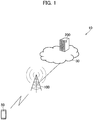
- FIG. 1 is an overall structural diagram of a radio communication system 10 according to the present embodiment.
- the radio communication system 10 is a radio communication system using 5G New Radio (NR) and includes a user device 50 (hereinafter, UE 50), a radio base station 100 (hereinafter, gNB 100) and a core network node 200 (hereinafter, CN 200).
- NR 5G New Radio
- UE 50 user device 50
- gNB 100 radio base station 100
- CN 200 core network node 200
- the radio communication system 10 is not necessarily limited to the radio communication system using the NR.
- the radio communication system 10 can be a radio communication system using an LTE (E-UTRAN).
- the UE 50 and the gNB 100 perform radio communication using NR. Particularly, in the present embodiment, the UE 50 transmits towards the gNB 100 and the CN 200, the UE Capability (capability information) that indicates the capabilities supported by the UE 50, and also a UE Capability ID (identifier) that uniquely identifies the UE Capability.
- the UE Capability Capability information
- identifier UE Capability ID
- the CN 200 is a network device that constitutes a core network 30, and provides mobility management function, and the like of the UE 50. Particularly, in the present embodiment, the CN 200 manages the association of a plurality of UE Capabilities with the UE Capability IDs.
- CN 200 As a concrete example of the CN 200, the example of Access and Mobility Management Function (AMF) is cited. But the function of CN 200 can be included in the other network devices, without being limited to AMF.
- AMF Access and Mobility Management Function
- a functional block configuration of the radio communication system 10 is explained below. Specifically, functional block configurations of the UE 50, the gNB 100 and the CN 200 are explained below. For convenience, the following explanation is given in the order of the CN 200, the gNB 100, and the UE 50.
- FIG. 2 is a functional block diagram of the CN 200.
- the CN 200 includes an identifier acquiring unit 210, a capability information managing unit 220, a management table retaining unit 230, and an acquisition instruction transmitting unit 240.
- the identifier acquiring unit 210 acquires from the UE 50 the identifier of the UE Capability that indicates the capability of the UE 50. Specifically, the identifier acquiring unit 210 acquires the UE Capability IDs that uniquely identify the respective UE Capabilities having mutually same contents.
- the method of assigning the UE Capability ID is not limited to any particular method.
- the result obtained by inputting the content of the UE Capability into the hash function can be used as the UE Capability ID.
- the gNB 100 and the CN 200 use the UE Capability to perform various controls of the UE 50.
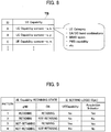
- the UE Capability includes a UE Category, CA (Carrier Aggregation) / DC (Dual Connectivity) band combinations, MIMO layers, a PWS (Public Warning System) capability, and the like.
- the identifier acquiring unit 210 can acquire the UE Capability ID transmitted from the UE 50, by using the message of Non-Access Stratum (NAS) between the UE 50 and the core network 30, more specifically, the CN 200.
- NAS Non-Access Stratum
- the identifier acquiring unit 210 can acquire the UE Capability ID that is included in the Attach Request. Moreover, the identifier acquiring unit 210 can, without limiting to an Attach Request, request for identifier acquisition by issuing a Security Mode Command or an Identity Request to get a Security Mode Complete or Identity Response message that includes the UE Capability ID.
- the identifier acquiring unit 210 can, by using the message of Access Stratum between the UE 50 and the gNB 100, acquire the UE Capability ID transmitted from the UE 50. Specifically, the identifier acquiring unit 210 acquires the UE Capability ID included in the Initial UE Message transmitted from the gNB 100 to the CN 200, in accordance with RRC Connection Setup Complete transmitted by the UE 50 to the gNB 100.
- the capability information managing unit 220 manages the UE Capabilities and the UE Capability IDs by associating them with each other. Specifically, the capability information managing unit 220 registers new and updates the existing associations in the management table retained by the management table retaining unit 230.
- FIG. 8 shows an example of the management table.
- the management table TB is constituted by the UE Capability IDs (the "ID" shown in the figure) associated with the respective UE Capabilities.
- the UE Capability includes UE Category and the like, whereas the UE Capability ID can uniquely identify the contents of the UE Capability.
- the management table retaining unit 230 retains the management table TB, which contains the UE Capability IDs and the UE Capabilities associated with them. Specifically, the management table retaining unit 230 modifies the contents of the management table TB, based on an instruction from the capability information managing unit 220.
- the acquisition instruction transmitting unit 240 transmits to the gNB 100 an instruction to acquire the UE Capability. Specifically, based on the UE Capability ID acquired by the identifier acquiring unit 210 and the UE Capability managed by the capability information managing unit 220, the acquisition instruction transmitting unit 240 transmits to the gNB 100, the instruction to acquire the UE Capability.
- the acquisition instruction transmitting unit 240 transmits such acquisition instruction when the UE Capability associated with the UE Capability ID acquired by the identifier acquiring unit 210 is not retained in the management table TB.
- the acquisition instruction transmitting unit 240 transmits the acquisition instruction by using an information element (IE) of the UE Capability that is included in the Initial Context Setup Request.
- IE information element
- the acquisition instruction transmitting unit 240 transmits the Initial Context Setup Request that includes the UE Capability associated with that ID.
- the acquisition instruction transmitting unit 240 does not include the respective UE Capability in the Initial Context Setup Request. Accordingly, it is possible to prompt the gNB 100 to acquire the UE Capability.
- the acquisition instruction is issued inexplicitly by omitting the respective UE Capability from the Initial Context Setup Request, but messages (or information elements) that explicitly indicate acquisition of UE Capability can also be used.
- the acquisition instruction transmitting unit 240 can transmit the Initial Context Setup Request (the acquisition instruction) that includes an Acquisition Indicator that indicates that the UE Capability associated with the UE Capability ID has already been retained.
- FIG. 3 is a functional block diagram of the gNB 100.
- the gNB 100 includes a radio communication unit 110, a message processing unit 115, an acquisition instruction receiving unit 120, a capability information enquiring unit 130, a capability information transmitting unit 140, a capability information managing unit 150, and a management table retaining unit 160.
- the radio communication unit 110 performs radio communication using the NR system. Specifically, the radio communication unit 110 transmits to / receives from the UE 50 a radio signal using the NR system. User data or control data are multiplexed in the radio signal. Moreover, the control data is transmitted / received by using a radio resource control layer (RRC layer) message.
- RRC layer radio resource control layer
- the message processing unit 115 performs processing of a message that is transmitted to / received from the UE 50. Moreover, the message processing unit 115 performs processing of a message that is transmitted to / received from the CN 200.
- the message processing unit 115 transmits / receives the messages of AS (RRC Connection Setup, RRC Connection Setup Complete, and the like) to / from the UE 50. Moreover, the message processing unit 115 transmits to and receives from the CN 200 the S1-AP messages (Initial UE Message, Initial Context Setup Request, and the like).
- AS RRC Connection Setup, RRC Connection Setup Complete, and the like
- S1-AP messages Initial UE Message, Initial Context Setup Request, and the like.
- the acquisition instruction receiving unit 120 receives the UE Capability acquisition instruction from the CN 200. Specifically, the acquisition instruction receiving unit 120 acquires the information element (IE) of the UE Capability that is included in the Initial Context Setup Request.
- IE information element
- the capability information enquiring unit 130 transmits based on the acquisition instruction received by the acquisition instruction receiving unit 120, a UE Capability enquiry to the UE 50. Specifically, when the acquisition instruction commands the capability information enquiring unit 130 to acquire the capability information of the UE 50, the capability information enquiring unit 130 transmits to the UE 50 the UE capability enquiry, which is the message of AS.
- the capability information enquiring unit 130 receives from the UE 50 the UE Capability information, which is a response message to the UE Capability Enquiry.
- the UE Capability information includes the UE Capability that indicates the capability of the UE 50.
- the capability information transmitting unit 140 transmits to the CN 200, the UE Capability received from the UE 50. Specifically, the capability information transmitting unit 140 acquires the UE Capability of the UE 50. The UE Capability is included in the UE Capability information received by the capability information enquiring unit 130. The capability information transmitting unit 140 transmits to the CN 200, the UE Capability Info Indication, which is an S1-AP message that includes the UE Capability.
- the capability information managing unit 150 manages the UE Capabilities and the UE Capability IDs by associating them with each other.
- the functions of the capability information managing unit 150 are substantially the same as that of the capability information managing unit 220 of the CN 200 explained above.
- the capability information managing unit 150 constitutes a capability information managing unit on the base station side.
- the capability information managing unit 150 which is generally installed only in the CN 200, can also be installed in the gNB 100 for managing the UE Capabilities and the UE Capability IDs by associating them with each other. In other words, the capability information managing unit 150 is not mandatory.
- the capability information managing unit 150 manages the UE Capabilities and the associated UE Capability IDs only when the UE 50 is in a Radio Resource Connection (RRC) established state. In other words, when the status of the UE 50 is RRC Idle, the capability information managing unit 150 does not manage the association of UE Capabilities and the UE Capability IDs of the UE 50, and deletes from the management table TB (see FIG. 8 ) the association of the UE Capabilities with the UE Capability IDs.
- RRC Radio Resource Connection
- the management table retaining unit 160 retains the management table TB, which contains the UE Capability IDs and the UE Capabilities associated with them.
- the function of the management table retaining unit 160 is substantially the same as that of the management table retaining unit 230 of the CN 200 explained above.
- the management table retaining unit 160 modifies the contents of the management table TB based on an instruction from the capability information managing unit 150.
- FIG. 4 is a functional block diagram of the UE 50.
- the UE 50 includes a radio communication unit 51, an identifier transmitting unit 53, an enquiry receiving unit 55, and a capability information transmitting unit 57.
- the radio communication unit 51 performs radio communication using the NR system. Specifically, the radio communication unit 51 transmits to / receives from the gNB 100 a radio signal using the NR system.
- the RRC layer message, user data, and the like are multiplexed in the radio signal.
- the identifier transmitting unit 53 transmits the UE Capability ID that identifies the UE Capability of the UE 50. Specifically, the identifier transmitting unit 53 can transmit the UE Capability ID to the gNB 100 by using the NAS message. For example, as explained above, the identifier transmitting unit 53 can transmit the Attach Request that includes the UE Capability ID. Moreover, the identifier transmitting unit 53 can, without limiting to the Attach Request, transmit the UE Capability ID along with the Security Mode Complete or Identity Response based on the request issued using Security Mode Command or Identity Request.
- the identifier transmitting unit 53 can also transmit the UE Capability ID to the gNB 100 by using the message of AS. Specifically, the identifier transmitting unit 53 can transmit the RRC Connection Setup Complete that includes the UE Capability ID.
- the enquiry receiving unit 55 receives an enquiry about the capability information transmitted by the gNB 100 (the capability information enquiring unit 130) . Specifically, the enquiry receiving unit 55 receives the UE Capability Enquiry that is transmitted by the gNB 100.
- the capability information transmitting unit 57 transmits, based on the enquiry received by the enquiry receiving unit 55, the capability information of the UE 50 to the gNB 100. Specifically, the capability information transmitting unit 57 transmits, based on the UE Capability Enquiry received by the enquiry receiving unit 55, the UE Capability of the UE 50 to the gNB 100.
- Radio communication system 10 Operation of the radio communication system 10 is explained below. Specifically, acquisition of the capability information by using the identifier (UE Capability ID) that identifies the capability information (UE Capability) of the UE 50 as well as the registration and update operations of the associations between capabilities and identifiers are explained.
- UE Capability ID the identifier that identifies the capability information (UE Capability) of the UE 50 as well as the registration and update operations of the associations between capabilities and identifiers are explained.
- FIG. 5 shows the acquisition sequence of the UE Capability ID and the update sequence of the management table TB (operation example 1). As shown in FIG. 5 , a mandatory sequence is indicated by a solid line, and a non-mandatory, that is, an optional sequence is indicated by a broken line.
- the UE 50 transmits to the gNB 100 an RRC Connection Request to establish an RRC connection.
- the gNB 100 returns to the UE 50 an RRC Connection Setup, which is a response to the RRC Connection Request (Steps 1, 2). Accordingly, settings related to RRC connection are performed.
- the UE 50 transmits, upon completion of the settings, the RRC Connection Setup Complete to the gNB 100 (Step 3).
- the RRC Connection Setup Complete includes an Attach Request, which is a NAS message.
- the gNB 100 transmits to the CN 200 an Initial UE Message that includes the Attach Request (Step 4).
- the Attach Request includes the UE Capability ID that identifies the UE Capability of the UE 50.
- the UE 50 can use other NAS messages, specifically, Security Mode Complete or Identity Response, to transmit the UE Capability ID to the CN 200 (Steps 6, 7). More specifically, the CN 200 can request for acquisition of the UE Capability ID by using Security Mode Command or Identity Request, and the UE 50 can transmit Security Mode Complete or Identity Response that includes the UE Capability ID.
- the CN 200 can request for acquisition of the UE Capability ID by using Security Mode Command or Identity Request, and the UE 50 can transmit Security Mode Complete or Identity Response that includes the UE Capability ID.
- the CN 200 acquires the UE Capability ID included in the NAS message and judges whether or not to acquire the UE Capability of the UE 50 (Step 7a).
- the CN 200 transmits the Initial Context Setup Request that includes the associated UE Capability (Option (Opt.) UE Capability in the figure) (Step 8). Accordingly, in this case, the CN 200 performs various controls of the UE 50 by using the UE Capability retained in the management table TB.
- the CN 200 does not include the UE Capability in the Initial Context Setup Request. Accordingly, it is possible to prompt the gNB 100 to acquire the UE Capability.
- the gNB 100 judges, based on the UE Capability included in the Initial Context Setup Request, whether or not to acquire the UE Capability of the UE 50 (step 8a). Specifically, when the UE Capability is not included in the Initial Context Setup Request, the gNB 100 judges that the UE Capability of the UE 50 be acquired.
- the gNB 100 transmits the UE Capability Enquiry to the UE 50 (Step 9).
- the UE 50 returns to the gNB 100 the UE Capability information that includes the UE Capability of the UE 50 (Step 10).
- the gNB 100 stores the received UE Capability (Step 10a). Moreover, when the gNB 100 receives the UE Capability information that includes the UE Capability, it transmits the UE Capability Info Indication to the CN 200 (Step 11) . Furthermore, when the UE Capability is included in the Initial Context Setup Request, the gNB 100 does not execute Steps 9 and 11 and stores the UE Capability received at Step 8 (Step 10a).
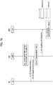
- FIG. 6 shows the acquisition sequence of the UE Capability ID and the update sequence of the management table TB (operation example 2).
- a part of the communication sequence that is different from the sequence explained in operation example 1 is mainly explained below, and a part that is similar to the operation example 1 is appropriately omitted.
- the NAS message is used in the UE Capability ID (identifier) notification, but in the present operation example, the message of AS is used.
- the UE 50 transmits to the gNB 100 the RRC Connection Setup Complete that includes the UE Capability ID (Step 3). Moreover, the gNB 100 transmits to the CN 200 the Initial UE Message that includes the UE Capability ID (Step 4). That is, the gNB 100 transfers the UE Capability ID included in the RRC Connection Setup Complete to the Initial UE Message.
- FIGS. 7A and 7B show the acquisition sequence of the UE Capability ID and the update sequence of the management table TB (operation example 3).
- a part of the communication sequence that is different from the sequence explained in operation example 1 and 2 is mainly explained below, and a part that is similar to the operation example 1 and 2 is appropriately omitted.
- the NAS message is used in the UE Capability ID (identifier) notification, but in the present operation example, the message of AS is used.
- the operation example 2 also uses the same type of message. Furthermore, in the present operation example, both the CN 200 and the gNB 100 retain and update the management table TB.
- the gNB 100 acquires the UE Capability ID included in the RRC Connection Setup Complete and judges whether or not to acquire the UE Capability of the UE 50 (Step 3a).
- the gNB 100 transmits an Initial UE Message that includes an Acquisition Indicator and a UE Capability ID that indicate that the UE Capability associated with the UE Capability ID has already been retained (Step 4) .
- the gNB 100 transmits the Initial UE Message that includes only the UE Capability ID and not the Acquisition Indicator.
- the CN 200 judges, based on the received UE Capability ID and on the presence or absence of the Acquisition Indicator, whether or not to acquire the UE Capability of the UE 50 (Step 7a) .
- the CN 200 determines, based on whether the UE Capability ID is registered in the management table TB and whether the Acquisition Indicator is present, the setting contents of the information element (IE), specifically, Opt. UE Capability and Opt. Indicator, to be included in the Initial Context Setup Request.
- IE information element
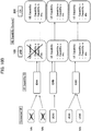
- FIG. 9 shows the setting logic of the information element (IE) included in the Initial Context Setup Request.
- the Acquisition Indicator (Opt. Indicator) indicates whether or not the UE Capability associated with the UE Capability ID is retained in the management table TB of the CN 200. If the UE Capability is retained, the Acquisition Indicator is set (Yes in the figure) accordingly.
- whether the UE Capability is to be included (Yes in the figure) or not (No in the figure) is set in accordance with whether or not the UE Capability is retained in the management table TB of the gNB 100 and CN 200. Furthermore, in both the operation examples 1 and 2, in the case of pattern 1, specifically, when the UE Capability is already retained in the CN 200, the UE Capability was set to Yes (that is, include UE Capability), but in the present operation example, even in such a case, the UE Capability is set to No. Accordingly, the amount of data signals attributable to the transmission of the UE Capability can be saved. Moreover, because the gNB 100 already has the UE Capability in its management table TB, the CN 200 need not transmit the UE Capability.
- the UE Capability can be assumed to be retained in a state shown in pattern 3, but it cannot basically be retained in a state shown in pattern 2 (excluding, however, the cases of failure of the CN 200, and the like).
- the CN 200 transmits to the gNB 100 an Initial Context Setup Request that includes the UE Capability and the Acquisition Indicator determined by such setting logic (Step 8) .
- the gNB 100 judges whether or not to acquire the UE Capability of the UE 50 (Step 8a).
- the gNB 100 judges, when the UE Capability is set in the Initial Context Setup Request, or when the UE Capability is not set in the Initial Context Setup Request but the Acquisition Indicator is set (Yes), that the UE Capability of the UE 50 not be acquired. On the other hand, when the setting logic of the UE Capability and the Acquisition Indicator is other than the above setting logics, the gNB 100 judges that the UE Capability of the UE 50 be acquired.
- Step 8a onwards is similar to that explained in operation example 2.
- the UE Capability ID is included in the RRC Connection Setup Complete and the Initial UE Message
- the Acquisition Indicator is included in the Initial UE Message and the Initial Context Setup Request.
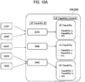
- FIGS. 10A and 10B each show an example of the methods of managing the UE Capability.
- FIG. 10A shows an example in which both the gNB 100 and the CN 200 always manage (store) the UE Capabilities having mutually same contents.
- FIG. 10B shows an example in which the gNB 100 manages (stores) the UE Capability only when the status of UE is RRC_CONNECTED.
- the data on the association between the UE Capability IDs and the UE Capabilities is always retained in the management table TB.
- the CN 200 acquires from the UE 50 the UE Capability identifier (UE Capability ID) that indicates the capability of the UE 50, and manages the UE Capabilities and the UE Capability IDs by associating them with each other. Moreover, based on the management conditions, the CN 200 transmits to the gNB 100 the instruction to acquire the UE Capability (Opt. UE Capability of the Initial Context Setup Request).
- UE Capability ID UE Capability identifier
- the CN 200 transmits to the gNB 100 the instruction to acquire the UE Capability (Opt. UE Capability of the Initial Context Setup Request).
- the gNB 100 acquires the UE Capability of the UE 50 based on the acquisition instructions.
- the gNB 100 can acquire the UE Capability only if the CN 200 has not retained the UE Capability ID and the associated UE Capability. Accordingly, when using the UE Capability identifier to acquire the UE Capability and send the notification of the UE Capability, it is possible to efficiently acquire the UE Capability and notify the CN 200 of the UE Capability.
- the present embodiment because it is possible to ease the unnecessary burden of managing duplicate UE Capabilities having mutually same contents, wastage of memory resources of the CN 200 can be prevented. Furthermore, because the number of UE Capability notifications (UE Capability information and UE Capability Info Indication) can be reduced, the amount of data signals attributable to the notifications of the UE Capabilities can also be saved.
- UE Capability notifications UE Capability information and UE Capability Info Indication
- the gNB 100 also retains the management table TB, it is possible to ease the unnecessary burden of managing duplicate UE Capabilities having mutually same contents, and to prevent the wastage of memory resources of the gNB 100.
- the message of NAS or AS can be used to acquire the UE Capability ID and notify the CN 200 of the UE Capability ID. Therefore, it is possible to select the suitable and appropriate mode of notifying and acquiring the UE Capability ID for the implementation of the radio communication system 10, and the like.
- the gNB 100 manages the UE Capabilities and the UE Capability IDs by associating them with each other only when the UE 50 is in an RRC established (RRC_CONNECTED) state. Therefore, it is possible to prevent the wastage of memory resources of the gNB 100 more effectively.
- the CN 200 can transmit, without setting the UE Capability, the Initial Context Setup Request that includes only the Acquisition Indicator that indicates that the UE Capability associated with the UE Capability ID has already been retained. As a result, the amount of data signals attributable to the notification of the UE Capability can be saved.
- each functional block may be realized by one device combined physically and / or logically.
- two or more devices separated physically and / or logically may be directly and / or indirectly connected (for example, wired and / or wireless) to each other, and each functional block may be realized by these plural devices.
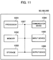
- FIG. 11 is a diagram showing an example of a hardware configuration of the devices. As shown in FIG. 11 , each of the devices can be configured as a computer device including a processor 1001, a memory 1002, a storage 1003, a communication device 1004, an input device 1005, an output device 1006, and a bus 1007.
- the functional blocks of the devices can be realized by any of hardware elements of the computer device or a desired combination of the hardware elements.
- the processor 1001 for example, operates an operating system to control the entire computer.
- the processor 1001 can be configured with a central processing unit (CPU) including an interface with a peripheral device, a control device, a computing device, a register, and the like.
- CPU central processing unit
- the memory 1002 is a computer readable recording medium and is configured, for example, with at least one of ROM (Read Only Memory), EPROM (Erasable Programmable ROM), EEPROM (Electrically Erasable Programmable ROM), RAM (Random Access Memory), and the like.
- the memory 1002 can be called register, cache, main memory (main memory), and the like.
- the memory 1002 can store therein a computer program (computer program codes), software modules, and the like that can execute the method according to the above embodiments.
- the storage 1003 is a computer readable recording medium.
- Examples of the storage 1003 include an optical disk such as CD-ROM (Compact Disc ROM), a hard disk drive, a flexible disk, a magneto-optical disk (for example, a compact disk, a digital versatile disk, a Blu-ray (Registered Trademark) disk), a smart card, a flash memory (for example, a card, a stick, a key drive), a floppy (Registered Trademark) disk, a magnetic strip, and the like.
- the storage 1003 can be called an auxiliary storage device.
- the recording medium can be, for example, a database including the memory 1002 and / or the storage 1003, a server, or other appropriate medium.
- the communication device 1004 is hardware (transmission / reception device) capable of performing communication between computers via a wired and / or wireless network.
- the communication device 1004 is also called, for example, a network device, a network controller, a network card, a communication module, and the like.
- the input device 1005 is an input device (for example, a keyboard, a mouse, a microphone, a switch, a button, a sensor, and the like) that accepts input from the outside.
- the output device 1006 is an output device (for example, a display, a speaker, an LED lamp, and the like) that outputs data to the outside. Note that, the input device 1005 and the output device 1006 may be integrated (for example, a touch screen).
- the respective devices such as the processor 1001 and the memory 1002, are connected to each other with the bus 1007 for communicating information there among.
- the bus 1007 can be constituted by a single bus or can be constituted by separate buses between the devices.
- the manner of notification of information is not limited to the one explained in the embodiments, and the notification may be performed in other manner.
- the notification of information can be performed by physical layer signaling (for example, DCI (Downlink Control Information), UCI (Uplink Control Information)), upper layer signaling (for example, RRC signaling, MAC (Medium Access Control) signaling, notification information (MIB (Master Information Block), SIB (System Information Block)), other signals, or a combination thereof.
- the RRC signaling can be called an RRC message
- the RRC signaling can be, for example, an RRC Connection Setup message, an RRC Connection Reconfiguration message, and the like.
- the input / output information can be stored in a specific location (for example, a memory) or can be managed in a management table.
- the information to be input / output can be overwritten, updated, or added.
- the information can be deleted after outputting.
- the inputted information can be transmitted to another device.
- the specific operations performed by the gNB 100 and the CN 200 can be performed by another network node (device).
- functions of the gNB 100 and the CN 200 can be provided by combining a plurality of other network nodes.
- the used parameter and the like can be represented by an absolute value, can be expressed as a relative value from a predetermined value, or can be represented by corresponding other information.
- the radio resource can be indicated by an index.
- the gNB 100 can accommodate one or more (for example, three) cells (also called sectors).
- the entire coverage area of the base station can be divided into a plurality of smaller areas.
- communication service can be provided by a base station subsystem (for example, a small base station for indoor use RRH: Remote Radio Head).
- the term “cell” or “sector” refers to a part or all of the coverage area of a base station and / or a base station subsystem that performs communication service in this coverage.
- base station eNB
- cell refers to a part or all of the coverage area of a base station and / or a base station subsystem that performs communication service in this coverage.
- base station eNB
- cell refers to a part or all of the coverage area of a base station and / or a base station subsystem that performs communication service in this coverage.
- base station eNodeB
- gNB gNodeB
- an access point a femtocell, a small cell, and the like.
- the UE 50 is called by the persons skilled in the art as a subscriber station, a mobile unit, a subscriber unit, a radio unit, a remote unit, a mobile device, a radio device, a radio communication device, a remote device, a mobile subscriber station, an access terminal, a mobile terminal, a radio terminal, a remote terminal, a handset, a user agent, a mobile client, a client, or with some other suitable term.
- the phrase “based on” does not mean “based only on” unless explicitly stated otherwise. In other words, the phrase “based on” means both “based only on” and “based at least on”.
- any reference to an element using a designation such as “first”, “second”, and the like used in the present specification generally does not limit the amount or order of those elements. Such designations can be used in the present specification as a convenient way to distinguish between two or more elements. Thus, the reference to the first and second elements does not imply that only two elements can be adopted, or that the first element must precede the second element in some or the other manner.
- the present invention is useful in that, when using the UE Capability identifier to acquire the UE Capability and send the notification of the UE Capability, it is possible to efficiently acquire the UE Capability and send the notification of the UE Capability.
Landscapes
- Engineering & Computer Science (AREA)
- Computer Networks & Wireless Communication (AREA)
- Signal Processing (AREA)
- Databases & Information Systems (AREA)
- Mobile Radio Communication Systems (AREA)
Applications Claiming Priority (2)
| Application Number | Priority Date | Filing Date | Title |
|---|---|---|---|
| JP2017155811 | 2017-08-10 | ||
| PCT/JP2018/029742 WO2019031540A1 (fr) | 2017-08-10 | 2018-08-08 | Système de communication sans fil, dispositif de réseau, dispositif utilisateur, station de base sans fil, et procédé de communication sans fil |
Publications (2)
| Publication Number | Publication Date |
|---|---|
| EP3668131A1 true EP3668131A1 (fr) | 2020-06-17 |
| EP3668131A4 EP3668131A4 (fr) | 2021-04-21 |
Family
ID=65272353
Family Applications (1)
| Application Number | Title | Priority Date | Filing Date |
|---|---|---|---|
| EP18844358.4A Withdrawn EP3668131A4 (fr) | 2017-08-10 | 2018-08-08 | Système de communication sans fil, dispositif de réseau, dispositif utilisateur, station de base sans fil, et procédé de communication sans fil |
Country Status (5)
| Country | Link |
|---|---|
| US (1) | US11647381B2 (fr) |
| EP (1) | EP3668131A4 (fr) |
| JP (1) | JP7168569B2 (fr) |
| CN (1) | CN111164996B (fr) |
| WO (1) | WO2019031540A1 (fr) |
Cited By (1)
| Publication number | Priority date | Publication date | Assignee | Title |
|---|---|---|---|---|
| EP3852411A4 (fr) * | 2019-03-28 | 2021-12-15 | Guangdong Oppo Mobile Telecommunications Corp., Ltd. | Procédé et dispositif de distribution d'identifiant de capacité |
Families Citing this family (13)
| Publication number | Priority date | Publication date | Assignee | Title |
|---|---|---|---|---|
| GB2566965A (en) * | 2017-09-28 | 2019-04-03 | Samsung Electronics Co Ltd | Improvements in and relating to connection setup |
| CN112738893B (zh) * | 2018-09-21 | 2022-04-12 | 华为技术有限公司 | 用户终端的能力信息传输方法、相关装置、存储介质及系统 |
| WO2020067987A1 (fr) * | 2018-09-27 | 2020-04-02 | Telefonaktiebolaget Lm Ericsson (Publ) | Distribution incrémentale d'informations de capacité d'équipement utilisateur à l'aide d'un identificateur de modèle |
| EP3834444B1 (fr) * | 2018-10-03 | 2023-08-09 | Sony Group Corporation | Procédé d'identification de capacités d'un terminal dans un réseau sans fil |
| US10701700B2 (en) * | 2018-10-29 | 2020-06-30 | Apple Inc. | Signaling messaging and UE capability with tag and compression |
| WO2020106200A1 (fr) * | 2018-11-20 | 2020-05-28 | Telefonaktiebolaget Lm Ericsson (Publ) | Signalisation d'informations de capacité radio entre un nœud radio et un nœud de fonction de gestion d'accès et de mobilité (amf) |
| WO2020164097A1 (fr) | 2019-02-15 | 2020-08-20 | Zte Corporation | Signalisation d'identifiants de capacités de dispositifs |
| CN111866992B (zh) * | 2019-04-30 | 2022-04-05 | 华为技术有限公司 | 一种通信方法及装置 |
| EP3963830A1 (fr) * | 2019-05-01 | 2022-03-09 | Nokia Technologies Oy | Signalisation de capacités d'équipement utilisateur optimisée comprenant la récupération à partir d'une défaillance de base de données |
| US11611948B2 (en) * | 2019-05-02 | 2023-03-21 | Qualcomm Incorporated | Paging techniques for balanced power savings and public warning system monitoring |
| WO2020227897A1 (fr) * | 2019-05-13 | 2020-11-19 | Guangdong Oppo Mobile Telecommunications Corp.,Ltd. | Appareil et procédé destinés à l'interfonctionnement de système |
| EP3981182A1 (fr) * | 2019-06-04 | 2022-04-13 | Sony Group Corporation | Procédé de gestion des capacités de terminal dans un réseau de communication sans fil |
| WO2021094070A1 (fr) * | 2019-11-15 | 2021-05-20 | Sony Corporation | Procédé et appareil permettant de gérer des capacités d'équipement utilisateur dans un réseau sans fil |
Family Cites Families (16)
| Publication number | Priority date | Publication date | Assignee | Title |
|---|---|---|---|---|
| WO2012111971A2 (fr) * | 2011-02-15 | 2012-08-23 | Samsung Electronics Co., Ltd. | Procédé et appareil pour service poste à poste dans un système de communication sans fil |
| GB2493705A (en) * | 2011-08-11 | 2013-02-20 | Nec Corp | Mobile radio communications performance measurement and network optimization |
| CN102932765B (zh) * | 2011-08-12 | 2015-06-03 | 华为技术有限公司 | 能力信息获取的方法及设备 |
| WO2014047949A1 (fr) * | 2012-09-29 | 2014-04-03 | 华为技术有限公司 | Procédé, dispositif et système de communication coopérative multiutilisateur |
| US9253809B2 (en) * | 2012-10-05 | 2016-02-02 | Qualcomm Incorporated | Apparatus and methods for improved user equipment (UE) capability signaling |
| CN106664549B (zh) * | 2014-08-15 | 2020-05-19 | 苹果公司 | 用于性能信息设置的演进节点b和用户设备的方法和装置 |
| US10631287B2 (en) * | 2014-09-26 | 2020-04-21 | Samsung Electronics Co., Ltd. | Method and apparatus for supporting multi-radio access technology |
| WO2017078580A1 (fr) * | 2015-11-02 | 2017-05-11 | Telefonaktiebolaget Lm Ericsson (Publ) | Gestion de capacités de dispositif |
| JP6144369B1 (ja) | 2016-01-07 | 2017-06-07 | 株式会社Nttドコモ | 基地局、及びコンテクスト情報保持方法 |
| JP6651633B2 (ja) * | 2016-01-07 | 2020-02-19 | 華為技術有限公司Huawei Technologies Co.,Ltd. | データスケジューリング方法、基地局およびシステム |
| CN110463231A (zh) * | 2017-03-24 | 2019-11-15 | 英特尔公司 | 用于基于组的服务配给的系统和方法 |
| CN110786024B (zh) * | 2017-07-31 | 2023-09-08 | 华为技术有限公司 | 一种定位辅助数据的发送方法、设备及系统 |
| GB2566965A (en) * | 2017-09-28 | 2019-04-03 | Samsung Electronics Co Ltd | Improvements in and relating to connection setup |
| WO2019086309A1 (fr) * | 2017-10-30 | 2019-05-09 | Sony Corporation | Dispositif terminal, équipement d'infrastructure et procédés associés |
| ES2921051T3 (es) * | 2018-05-11 | 2022-08-17 | Guangdong Oppo Mobile Telecommunications Corp Ltd | Método de transmisión de señales, estación base y nodo de red |
| US11910391B2 (en) * | 2018-08-10 | 2024-02-20 | Google Llc | Methods and apparatus for an uplink control channel in NOMA asynchronous transmissions |
-
2018
- 2018-08-08 EP EP18844358.4A patent/EP3668131A4/fr not_active Withdrawn
- 2018-08-08 WO PCT/JP2018/029742 patent/WO2019031540A1/fr unknown
- 2018-08-08 US US16/637,580 patent/US11647381B2/en active Active
- 2018-08-08 CN CN201880064473.4A patent/CN111164996B/zh active Active
- 2018-08-08 JP JP2019535698A patent/JP7168569B2/ja active Active
Cited By (1)
| Publication number | Priority date | Publication date | Assignee | Title |
|---|---|---|---|---|
| EP3852411A4 (fr) * | 2019-03-28 | 2021-12-15 | Guangdong Oppo Mobile Telecommunications Corp., Ltd. | Procédé et dispositif de distribution d'identifiant de capacité |
Also Published As
| Publication number | Publication date |
|---|---|
| EP3668131A4 (fr) | 2021-04-21 |
| US20200260264A1 (en) | 2020-08-13 |
| CN111164996B (zh) | 2023-05-02 |
| JP7168569B2 (ja) | 2022-11-09 |
| WO2019031540A1 (fr) | 2019-02-14 |
| US11647381B2 (en) | 2023-05-09 |
| CN111164996A (zh) | 2020-05-15 |
| JPWO2019031540A1 (ja) | 2020-08-20 |
Similar Documents
| Publication | Publication Date | Title |
|---|---|---|
| US11647381B2 (en) | Radio communication system, network device, user device, radio base station and radio communication method | |
| US10952276B2 (en) | Radio communication system | |
| US11323976B2 (en) | Network device and radio communication method | |
| CN110999440B (zh) | 无线基站及无线通信方法 | |
| US10542580B2 (en) | Radio communication system | |
| US11323311B2 (en) | Radio communication system and radio base station | |
| US11523454B2 (en) | Radio communication system and radio communication method | |
| US11265967B2 (en) | User device for setting packet data convergence protocol entity in dual connectivity | |
| JP6751717B2 (ja) | 無線通信システム、ゲートウェイ装置、移動管理エンティティ及び通信制御方法 | |
| EP3668267B1 (fr) | Station de base de radio et procédé de commande de communication | |
| CA3033340A1 (fr) | Generation d'un marqueur terminal d'un flux de donnees dans le controle des transferts axes sur les flux | |
| US11825538B2 (en) | Radio communication system and radio base station | |
| JPWO2019193879A1 (ja) | ユーザ装置、ネットワーク装置及び無線通信方法 |
Legal Events
| Date | Code | Title | Description |
|---|---|---|---|
| STAA | Information on the status of an ep patent application or granted ep patent |
Free format text: STATUS: THE INTERNATIONAL PUBLICATION HAS BEEN MADE |
|
| PUAI | Public reference made under article 153(3) epc to a published international application that has entered the european phase |
Free format text: ORIGINAL CODE: 0009012 |
|
| STAA | Information on the status of an ep patent application or granted ep patent |
Free format text: STATUS: REQUEST FOR EXAMINATION WAS MADE |
|
| 17P | Request for examination filed |
Effective date: 20200218 |
|
| AK | Designated contracting states |
Kind code of ref document: A1 Designated state(s): AL AT BE BG CH CY CZ DE DK EE ES FI FR GB GR HR HU IE IS IT LI LT LU LV MC MK MT NL NO PL PT RO RS SE SI SK SM TR |
|
| AX | Request for extension of the european patent |
Extension state: BA ME |
|
| DAV | Request for validation of the european patent (deleted) | ||
| DAX | Request for extension of the european patent (deleted) | ||
| A4 | Supplementary search report drawn up and despatched |
Effective date: 20210323 |
|
| RIC1 | Information provided on ipc code assigned before grant |
Ipc: H04W 8/22 20090101AFI20210317BHEP Ipc: H04W 92/04 20090101ALI20210317BHEP |
|
| STAA | Information on the status of an ep patent application or granted ep patent |
Free format text: STATUS: THE APPLICATION HAS BEEN WITHDRAWN |
|
| 18W | Application withdrawn |
Effective date: 20220725 |