EP3667634A1 - Method of assessing a pilot emotional state - Google Patents
Method of assessing a pilot emotional state Download PDFInfo
- Publication number
- EP3667634A1 EP3667634A1 EP19214621.5A EP19214621A EP3667634A1 EP 3667634 A1 EP3667634 A1 EP 3667634A1 EP 19214621 A EP19214621 A EP 19214621A EP 3667634 A1 EP3667634 A1 EP 3667634A1
- Authority
- EP
- European Patent Office
- Prior art keywords
- pilot
- emotional state
- flight
- data
- probability
- Prior art date
- Legal status (The legal status is an assumption and is not a legal conclusion. Google has not performed a legal analysis and makes no representation as to the accuracy of the status listed.)
- Ceased
Links
Images


Classifications
-
- G—PHYSICS
- G06—COMPUTING OR CALCULATING; COUNTING
- G06V—IMAGE OR VIDEO RECOGNITION OR UNDERSTANDING
- G06V40/00—Recognition of biometric, human-related or animal-related patterns in image or video data
- G06V40/10—Human or animal bodies, e.g. vehicle occupants or pedestrians; Body parts, e.g. hands
- G06V40/16—Human faces, e.g. facial parts, sketches or expressions
- G06V40/174—Facial expression recognition
-
- G—PHYSICS
- G06—COMPUTING OR CALCULATING; COUNTING
- G06V—IMAGE OR VIDEO RECOGNITION OR UNDERSTANDING
- G06V40/00—Recognition of biometric, human-related or animal-related patterns in image or video data
- G06V40/20—Movements or behaviour, e.g. gesture recognition
-
- G—PHYSICS
- G08—SIGNALLING
- G08B—SIGNALLING SYSTEMS, e.g. PERSONAL CALLING SYSTEMS; ORDER TELEGRAPHS; ALARM SYSTEMS
- G08B21/00—Alarms responsive to a single specified undesired or abnormal condition and not otherwise provided for
- G08B21/02—Alarms for ensuring the safety of persons
- G08B21/06—Alarms for ensuring the safety of persons indicating a condition of sleep, e.g. anti-dozing alarms
-
- A—HUMAN NECESSITIES
- A61—MEDICAL OR VETERINARY SCIENCE; HYGIENE
- A61B—DIAGNOSIS; SURGERY; IDENTIFICATION
- A61B5/00—Measuring for diagnostic purposes; Identification of persons
- A61B5/103—Measuring devices for testing the shape, pattern, colour, size or movement of the body or parts thereof, for diagnostic purposes
- A61B5/11—Measuring movement of the entire body or parts thereof, e.g. head or hand tremor or mobility of a limb
- A61B5/1126—Measuring movement of the entire body or parts thereof, e.g. head or hand tremor or mobility of a limb using a particular sensing technique
- A61B5/1128—Measuring movement of the entire body or parts thereof, e.g. head or hand tremor or mobility of a limb using a particular sensing technique using image analysis
-
- A—HUMAN NECESSITIES
- A61—MEDICAL OR VETERINARY SCIENCE; HYGIENE
- A61B—DIAGNOSIS; SURGERY; IDENTIFICATION
- A61B5/00—Measuring for diagnostic purposes; Identification of persons
- A61B5/16—Devices for psychotechnics; Testing reaction times ; Devices for evaluating the psychological state
- A61B5/163—Devices for psychotechnics; Testing reaction times ; Devices for evaluating the psychological state by tracking eye movement, gaze, or pupil change
-
- A—HUMAN NECESSITIES
- A61—MEDICAL OR VETERINARY SCIENCE; HYGIENE
- A61B—DIAGNOSIS; SURGERY; IDENTIFICATION
- A61B5/00—Measuring for diagnostic purposes; Identification of persons
- A61B5/16—Devices for psychotechnics; Testing reaction times ; Devices for evaluating the psychological state
- A61B5/165—Evaluating the state of mind, e.g. depression, anxiety
-
- A—HUMAN NECESSITIES
- A61—MEDICAL OR VETERINARY SCIENCE; HYGIENE
- A61B—DIAGNOSIS; SURGERY; IDENTIFICATION
- A61B5/00—Measuring for diagnostic purposes; Identification of persons
- A61B5/16—Devices for psychotechnics; Testing reaction times ; Devices for evaluating the psychological state
- A61B5/18—Devices for psychotechnics; Testing reaction times ; Devices for evaluating the psychological state for vehicle drivers or machine operators
-
- A—HUMAN NECESSITIES
- A61—MEDICAL OR VETERINARY SCIENCE; HYGIENE
- A61B—DIAGNOSIS; SURGERY; IDENTIFICATION
- A61B5/00—Measuring for diagnostic purposes; Identification of persons
- A61B5/68—Arrangements of detecting, measuring or recording means, e.g. sensors, in relation to patient
- A61B5/6887—Arrangements of detecting, measuring or recording means, e.g. sensors, in relation to patient mounted on external non-worn devices, e.g. non-medical devices
- A61B5/6888—Cabins
-
- A—HUMAN NECESSITIES
- A61—MEDICAL OR VETERINARY SCIENCE; HYGIENE
- A61B—DIAGNOSIS; SURGERY; IDENTIFICATION
- A61B5/00—Measuring for diagnostic purposes; Identification of persons
- A61B5/74—Details of notification to user or communication with user or patient; User input means
- A61B5/746—Alarms related to a physiological condition, e.g. details of setting alarm thresholds or avoiding false alarms
-
- B—PERFORMING OPERATIONS; TRANSPORTING
- B64—AIRCRAFT; AVIATION; COSMONAUTICS
- B64D—EQUIPMENT FOR FITTING IN OR TO AIRCRAFT; FLIGHT SUITS; PARACHUTES; ARRANGEMENT OR MOUNTING OF POWER PLANTS OR PROPULSION TRANSMISSIONS IN AIRCRAFT
- B64D45/00—Aircraft indicators or protectors not otherwise provided for
- B64D45/0015—Devices specially adapted for the protection against criminal attack, e.g. anti-hijacking systems
- B64D45/0051—Devices specially adapted for the protection against criminal attack, e.g. anti-hijacking systems by monitoring passengers or crew on aircraft
- B64D45/0053—Devices specially adapted for the protection against criminal attack, e.g. anti-hijacking systems by monitoring passengers or crew on aircraft using visual equipment, e.g. cameras
-
- G—PHYSICS
- G10—MUSICAL INSTRUMENTS; ACOUSTICS
- G10L—SPEECH ANALYSIS TECHNIQUES OR SPEECH SYNTHESIS; SPEECH RECOGNITION; SPEECH OR VOICE PROCESSING TECHNIQUES; SPEECH OR AUDIO CODING OR DECODING
- G10L25/00—Speech or voice analysis techniques not restricted to a single one of groups G10L15/00 - G10L21/00
- G10L25/48—Speech or voice analysis techniques not restricted to a single one of groups G10L15/00 - G10L21/00 specially adapted for particular use
- G10L25/51—Speech or voice analysis techniques not restricted to a single one of groups G10L15/00 - G10L21/00 specially adapted for particular use for comparison or discrimination
- G10L25/63—Speech or voice analysis techniques not restricted to a single one of groups G10L15/00 - G10L21/00 specially adapted for particular use for comparison or discrimination for estimating an emotional state
-
- A—HUMAN NECESSITIES
- A61—MEDICAL OR VETERINARY SCIENCE; HYGIENE
- A61B—DIAGNOSIS; SURGERY; IDENTIFICATION
- A61B2503/00—Evaluating a particular growth phase or type of persons or animals
- A61B2503/20—Workers
- A61B2503/22—Motor vehicles operators, e.g. drivers, pilots, captains
-
- A—HUMAN NECESSITIES
- A61—MEDICAL OR VETERINARY SCIENCE; HYGIENE
- A61B—DIAGNOSIS; SURGERY; IDENTIFICATION
- A61B5/00—Measuring for diagnostic purposes; Identification of persons
- A61B5/0059—Measuring for diagnostic purposes; Identification of persons using light, e.g. diagnosis by transillumination, diascopy, fluorescence
- A61B5/0077—Devices for viewing the surface of the body, e.g. camera, magnifying lens
-
- A—HUMAN NECESSITIES
- A61—MEDICAL OR VETERINARY SCIENCE; HYGIENE
- A61B—DIAGNOSIS; SURGERY; IDENTIFICATION
- A61B5/00—Measuring for diagnostic purposes; Identification of persons
- A61B5/68—Arrangements of detecting, measuring or recording means, e.g. sensors, in relation to patient
- A61B5/6887—Arrangements of detecting, measuring or recording means, e.g. sensors, in relation to patient mounted on external non-worn devices, e.g. non-medical devices
- A61B5/6893—Cars
-
- B—PERFORMING OPERATIONS; TRANSPORTING
- B64—AIRCRAFT; AVIATION; COSMONAUTICS
- B64D—EQUIPMENT FOR FITTING IN OR TO AIRCRAFT; FLIGHT SUITS; PARACHUTES; ARRANGEMENT OR MOUNTING OF POWER PLANTS OR PROPULSION TRANSMISSIONS IN AIRCRAFT
- B64D45/00—Aircraft indicators or protectors not otherwise provided for
- B64D45/0015—Devices specially adapted for the protection against criminal attack, e.g. anti-hijacking systems
- B64D45/0059—Devices specially adapted for the protection against criminal attack, e.g. anti-hijacking systems by communicating emergency situations to ground control or between crew members
Definitions
- Contemporary aircraft travel flight paths that generally includes a climb, a cruise, and a descent. Pilots along with flight management systems (FMS) implement the flight plan.
- the FMS may generate the flight plan by taking into account parameters specific to the aircraft and to the flight conditions such as the payload, the weight of the aircraft, the quantity of fuel onboard, temperature, wind, altitude, etc., and of the time constraints imposed by the air traffic control.
- the flight plan may describe all the waypoints or positions through which the aircraft is to pass, with the altitude and corresponding speed at each waypoint.
- Pilot emotion state can vary before takeoff or during the course of any flight. If real-time data of a pilot is indicative of an emotional state outside baseline pilot parameters, it can be beneficial to alert a ground crew to the pilot's emotional state. For example, if real-time pilot data shows a sudden spike or drop in pulse rate, this might be indicative of a pilot medical condition, to which the system might alert emergency medical personnel. In another example, if real-time pilot data before flight shows a pilot is angry or stressed beyond a normal pilot baseline model, it might be beneficial to alert a ground crew.
- the disclosure relates to a method of assessing a pilot emotional state and sending an alert based on the emotional state.
- the method includes tracking during a time period, using at least one sensor, one of an image sensor data, voice data or a biometric parameter of a pilot. Determining, using a controller that is operatively connected to at least one sensor, a probability of a likely emotional state from a list of emotional states of a pilot based on one of the image sensor data, voice data or the biometric parameter. Comparing, using a processor, the probability of one of the likely emotional states of the pilot with a baseline emotional state of the pilot. Sending, using the controller, an alert if most likely emotional state deviates from the baseline emotional state by a predetermined threshold.
- the disclosure relates to a method of adjusting a flight crew before a planned flight.
- the method includes tracking over a time period, using at least one sensor, image sensor data, voice data or a biometric parameter of a pilot over one or more flights of an aircraft before the planned flight. Determining during the one or more flights, using a controller that is operatively connected to the at least one sensor, a probability for each likely emotional state from a list of emotional states of a pilot based on one of the image sensor data, voice data or the biometric parameter. Comparing, using a processor, the probability of one of the likely emotional states of the pilot with a baseline model emotional state of the pilot. Determining if the emotional state of the pilot varies based on the flight crew. Adjusting, using the controller, the crew roster prior to the planned flight if the emotional state of the pilot is one of stress or anger when working with a specific flight crew.
- aspects of the present disclosure are directed to a method of assessing a pilot emotional state and sending an alert if the emotional state falls outside a predetermined threshold.
- emotional state means a pilot's current physical condition or behavior that is indicative a pilot's current state of mind. Prior to or during operation of an aircraft, it can be important to understand the emotional state of a pilot to understand if the pilot is stressed, angry, happy, relaxed, intoxicated, having a medical issue, etc. If a pilot is stressed, angry, intoxicated, or having a medical issue it may be beneficial to remove the pilot from service of the aircraft or in some cases alert medical personnel.
- a pilot's voice, body movements, eye movements and various biometric parameters such as heart rate and blood pressure can be monitored and stored as data.
- Baseline statistics can be stored that are indicative of pilot's emotional or behavioral state. These statistics can used as a comparison for understanding a pilot's current emotional state. For example, if real-time data of a pilot is indicative of anger, i.e. loud voice, darting eye movements, high pulse rate, the system might alert a ground crew to the pilot's emotional state. In another example, if the real-time data shows a sudden spike or drop in pulse rate, this might be indicative of a pilot medical condition, to which the system might alert emergency medical personal. In these cases, it might be beneficial to remove the pilot from service of the aircraft.
- pilot stress levels and behaviors can be function of the pilot's personal habits such as food intake, exercise, and even sleep habits.
- Baseline models of pilot's ordinary or typical emotional state can be developed to provide a threshold indictor of the pilot baseline emotional state characteristics.
- the pilot's emotional state can vary over time or even flight-to-flight. For example, if a pilot did not get much rest before a flight, the pilot might become stressed or angry more easily. In other words, fatigue might increase stress or anger sensitivity to workload and minor changes in pilot environment can have a larger detrimental impact.
- it can be beneficial to track a pilot's emotional state during flight and adjust the pilot's workload when the pilot's emotional state exceeds a predetermined threshold.
- a set can include any number of the respectively described elements, including only one element. All directional references (e.g., radial, axial, proximal, distal, upper, lower, upward, downward, left, right, lateral, front, back, top, bottom, above, below, vertical, horizontal, clockwise, counterclockwise, upstream, downstream, forward, aft, etc.) are only used for identification purposes to aid the reader's understanding of the present disclosure, and do not create limitations, particularly as to the position, orientation, or use of the disclosure. Connection references (e.g., attached, coupled, connected, and joined) are to be construed broadly and can include intermediate members between a collection of elements and relative movement between elements unless otherwise indicated. As such, connection references do not necessarily infer that two elements are directly connected and in fixed relation to one another.
- the exemplary drawings are for purposes of illustration only and the dimensions, positions, order, and relative sizes reflected in the drawings attached hereto can vary.
- a “controller” can include at least one processor and memory.
- the memory can include Random Access Memory (RAM), Read-Only Memory (ROM), flash memory, or one or more different types of portable electronic memory, such as discs, DVDs, CD-ROMs, etc., or any suitable combination of these types of memory.
- the processor can be configured to run any suitable programs or executable instructions designed to carry out various methods, functionality, processing tasks, calculations, or the like, to enable or achieve the technical operations or operations described herein.
- the program can include a computer program product that can include machine-readable media for carrying or having machine-executable instructions or data structures stored thereon.
- Such machine-readable media can be any available media, which can be accessed by a general purpose or special purpose computer or other machine with a processor.
- a computer program can include routines, programs, objects, components, data structures, algorithms, etc., that have the technical effect of performing particular tasks or implement particular abstract data types.
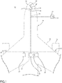
- FIG. 1 schematically illustrates an aircraft 10 according to various aspects described herein.
- One or more propulsion engines 12 can be coupled to a fuselage 14, a cockpit 16 can be positioned in the fuselage 14, and wing assemblies 18 can extend outward from the fuselage 14.
- a plurality of aircraft systems 20 that enable proper operation of the aircraft 10 can be included as well as a flight control computer 22 (or "computer” 22). While a commercial aircraft has been illustrated, it is contemplated that aspects of the disclosure can be used in any type of legacy aircraft, for example, without limitation, fixed-wing, rotating-wing, rocket, or personal aircraft.
- the plurality of aircraft systems 20 can reside within the cockpit 16, within an electronics and equipment bay 23, or in other locations throughout the aircraft 10 including that they can be associated with the engines 12.
- Such aircraft systems 20 can include but are not limited to: an electrical system, an oxygen system, hydraulics and/or pneumatics system, a fuel system, a propulsion system, navigation systems, flight controls, audio/video systems, an Integrated Vehicle Health Management (IVHM) system, and systems associated with the mechanical structure of the aircraft 10.
- IVHM Integrated Vehicle Health Management
- a variety of aircraft systems 20 have been illustrated for exemplary purposes and it will be understood that they are only a few of the systems that can be included in the aircraft 10.
- a data network 26 over which the plurality of aircraft systems 20 can communicate with each other and provide information to a crew of the aircraft 10 can be included.
- the aircraft systems 20 can output various information to a flight deck 30 located in a cockpit 16 of the aircraft 10.
- a communication interface 40 can be located within the aircraft 10 and operably coupled to at least some of the plurality of aircraft systems 20.
- the communication interface 40 has been illustrated as being included in the cockpit 16. It is contemplated that the communication interface 40 can be located in other locations within the aircraft 10 including within the electronics and equipment bay 23. Although only one communication interface 40 has been illustrated, it is contemplated that the aircraft 10 can have multiple communication interfaces.
- the communication interface 40 can be utilized for communication with other aircraft or a ground station 31, such as by radio contact in a non-limiting example.
- the communication interface 40 can transmit or receive data, including audio or visual data as appropriate.
- the ground station 31 can be in communication with the data network 26 or communication interface 40.
- the ground station 31 can have a processor and software and capabilities for uploading or downloading software or data to the aircraft.
- the ground station 31 might also capability to store, analyze, and manipulate flight data with data analysis or other statistical software.
- the aircraft 10 might also have a computing system capable of storing, analyzing, and manipulating flight data with data analysis or other statistical software.
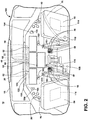
- FIG. 2 illustrates a portion of the cockpit 16 of the aircraft 10 and an exemplary flight deck 30 having various instruments 50 and flight displays 52.
- a first pilot (herein, a "pilot”) can be present in a seat 54 at the left side of the cockpit 16 and a second pilot (herein, a "co-pilot”) can be present at the right side of the cockpit 16 in a seat 55 and the flight deck 30 can be located in front of the pilot and co-pilot and can provide the flight crew with information to aid in operating the aircraft 10.
- the flight displays 52 can include either primary flight displays or multi-function displays and can display a wide range of aircraft, flight, navigation, and other information used in the operation and control of the aircraft 10. Further, both the various instruments 50 and flight displays 52 of the flight deck 30 can provide one or more visual indicia indicative of a corresponding health condition of one or more of the aircraft systems 20.
- the instruments 50 and flight displays 52 can be laid out in any manner including having fewer or more instruments or displays. Further, the flight displays 52 need not be coplanar and need not be the same size.
- a touch screen display or touch screen surface can be included in the flight display 52 and may be used by one or more flight crew members, including the pilot and co-pilot, to interact with the systems of the aircraft 10. Such touch screen surface can take any suitable form including that of a liquid crystal display (LCD) and can use various physical or electrical attributes to sense inputs from the flight crew. It is contemplated that the flight display 52 can be dynamic and that one or more cursor control devices 56 and/or one or more multifunction keyboards 58 can be included in the cockpit 16 and can be used by one or more flight crew members to interact with the systems of the aircraft 10. In this manner, the flight deck 30 can be considered a user interface for the aircraft systems 20 and the aircraft 10.
- the flight control computer 22 can be operably coupled to components of the aircraft 10 including the aircraft systems 20, instruments 50, flight displays 52, touch screen surfaces, cursor control devices 56, keyboards 58, etc.
- the flight control computer 22 can receive inputs from any number of aircraft systems 20 or software programs responsible for managing the acquisition and storage of data.
- the flight control computer 22 can also be in the form of a controller, and can be connected with other controllers of the aircraft 10.
- the flight control computer 22 can include memory 60 and processing units 62, which can be running any suitable programs to implement a graphical user interface (GUI) and operating system.
- GUI graphical user interface
- the flight control computer 22 can include or be associated with, any suitable number of individual microprocessors, power supplies, storage devices, interface cards, auto flight systems, flight management computers, and other standard components.
- the flight control computer 22 can include or cooperate with any number of software programs (e.g., flight management programs) or instructions designed to carry out the various methods, process tasks, calculations, and control/display functions necessary for operation of the aircraft 10.
- the communication interface 40 can be communicably coupled to the flight control computer 22 or other processors of the aircraft 10 as well as any number of the plurality of aircraft systems 20 to transfer information on and off the aircraft 10.
- the communication interface 40 can include any desired communication mechanism capable of wirelessly linking with other systems and devices, such as by radio contact in a non-limiting example.
- one of the aircraft systems 20 can be in the form of a distress tracker 21 configured to transmit a state of aircraft distress (for example, "normal,” "abnormal,” or "distressed").
- a pilot tracking system or tracking system 100 is illustrated as being in communication with the flight control computer 22. It will be understood that the tracking system 100 can be hard wired to the flight control computer 22 or can communicate in any suitable manner with the flight control computer 22 including via wireless communication. Alternatively, the tracking system 100 can be included as a module within the flight control computer 22.
- the tracking system 100 can include at least one imaging module 102 and at least one audio module 104.
- the imaging module 102 can include an image sensor 103 configured to sense visual information about a pilot or co-pilot, such as rapid eye movement, eyes moving one direction or another, being open or closed, a direction of gaze, or a facial state such as eyebrows raised or lowered, by way of non-limiting examples and provide an output signal based thereon.
- the image sensor 103 can be configured to capture or sense images beyond the human visible spectrum such as in the infrared, ultraviolet, electromagnetic or other range.
- An eye movement or body movement parameter can be stored by the tracking system 100
- the imaging module 102 or the flight control computer 22 can also be in signal communication with any of the flight displays 52, such as to display a visual indication based on the sensed visual information from the imaging module 102.
- the audio module 104 can include an audio sensor 105 configured to sense audio information about a pilot or co-pilot, such as a language being spoken in the cockpit 16, a voice volume, tone, slurred or altered speech, a speech pattern, or sounds that can occur due to pilot or co-pilot interaction with an aircraft system 20 such as striking the flight deck 30 or typing on the multifunction keyboard 58 and provide an output signal based thereon.
- the audio module 104 can be configured to use voice recognition and language analysis to help sense a pilot's emotional state.
- the audio module 104 can also provide audio feedback or sound to the pilot or co-pilot, such as through speakers mounted within the cockpit or through headphones worn by the pilot or co-pilot. Further, the audio module 104 can be in signal communication with the imaging module 102.
- the imaging module 102 can provide an indication for transmission through the audio module 104, such as spoken commands in a low-visibility environment within the cockpit 16.
- the audio module 104 can also provide a signal for transmission via the imaging module 102, such as a flashing light display or text-based indicator to be read by a pilot or co-pilot.
- At least one biometric sensor 106 configured to sense a biometric parameter of the pilot or co-pilot can be included in the tracking system 100.
- a biometric sensor 106 positioned on the first seat 54 can be configured to sense or detect a heart rate, breathing rate, perspiration rate, or bodily motion of the pilot when the pilot is sitting in the first seat 54.
- the biometric sensor 106 can be positioned on a wearable device such as a wrist strap or headband.
- the biometric sensor 106 can be in the form of an optical sensor, e.g. a camera that monitors the pilot or co-pilot.
- a seat tracking module 108 can control a seat distance 110 between the first seat 54 and the flight deck 30. While not shown, the second seat 55 can also include such a seat tracking module 108. Further, a seat belt sensor 112 can sense the position of a seat belt 70 on the first seat 54 or the second seat 55, such as the seat belt 70 being buckled or unbuckled.
- a haptic feedback generator 114 can be coupled or integrated with either or both of the first and second seats 54, 55.
- the haptic feedback generator 114 can be configured to vibrate, such as a steady or varying vibration pattern, to provide feedback to the pilot or co-pilot.
- the haptic feedback generator 114 can vibrate on a righthand portion or left-hand portion of the seat 54, 55 to indicate to a pilot or co-pilot which direction to bank the aircraft 10 for correct orientation when flying.
- a timer 115 can also be included in the tracking system 100 and is illustrated as being coupled to the flight deck 30.
- the timer 115 can be positioned anywhere within or outside of the cockpit 16.
- the timer 115 can be configured to track an elapsed time of an event or to provide an alarm or other indication at a predetermined time.
- Non-limiting examples where the timer 115 can be utilized include tracking an elapsed time of flight, an elapsed time of a pilot interaction with an aircraft system 20 (such as updating flight records via the multifunction keyboard 58), tracking an elapsed sleep time, indicating a time for changing a flight direction, or indicating a wake time.
- An additional controller 120 having a processor 122 and a memory 124 can also be included in the tracking system 100.
- the controller 120 is illustrated as being coupled to the flight deck 30 and in signal communication with any or all of the flight control computer 22, instruments 50, flight displays 52, memory 60, processing unit 62, imaging module 102, audio module 104, biometric sensor 106, seat tracking module 108, seat belt sensor 112, haptic feedback generator 114, or timer 115. Dashed lines have been used to illustrate a portion of the signal connection between the above-described components. The lack of a dashed line for signal connections is done for clarity of the figures, and it will be understood that components not connected by a dashed line can nonetheless be in signal communication.
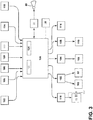
- FIG. 3 schematically illustrates components of the tracking system 100 in exemplary communicative connection, where a separate controller 120 is shown in signal connection with the various modules and sensors described above.
- the flight control computer 22 can be utilized or that each module or any combination of modules can include their own controller, processor, or memory.
- Arrows have been included to indicate an exemplary signal or control direction, and are provided for clarity in discussion. It will be understood that any signal communication or control between connected components in FIG. 3 can be transmitted in either direction, and an arrow's illustrated direction does not imply a one-way signal or control direction.
- a door lock module 116 with a door lock sensor 117 can further be included in the tracking system 100.
- a cockpit door 72 can include the door lock module 116 configured to sense whether the door 72 is locked or unlock.
- the module 116 can also automatically lock or unlock the door 72 based on a control signal within the tracking system 100.
- the controller 120 can be operably connected to and receive input from any or all of the flight control computer 22, image sensor 103, audio sensor 105, biometric sensor 106, seat tracking module 108, seat belt sensor 112, haptic feedback generator 114, timer 115, or door lock module 116. Any of the inputs received by the controller 120 can be stored in the memory 124.
- the memory 124 can store a history of audio input or recordings from data gathered within the cockpit 16, or an elapsed time since a pilot last interacted with a flight display 52 ( FIG. 2 ).
- the processor 122 of the controller 120 can send a signal or control command to any or all of the imaging module 102, audio module 104, seat tracking module 108, haptic feedback generator 114, or door lock module 116.
- the processor 122 can send a signal to the imaging module 102, such as a visual message to be read by the pilot or co-pilot on the flight display 52, or a command to enable or disable the image sensor 103.
- controller 120 of the tracking system 100 can issue a signal or command to another aircraft system, such as the communication interface 40 via the flight control computer 22.
- the controller 120 can communicate with an external aircraft or ground station (not shown).
- the controller 120 can also be communicatively coupled with any other aircraft system 20 as desired.
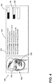
- FIG. 4 is an illustration of a captured image 130 of a pilot from image sensor 103 and illustrates one exemplary way of assessing a pilot's emotional state.
- the image sensor 103 can capture the facial expression 138 of the pilot at a particular point in time.
- the facial expression 138 can be analyzed by facial recognition software 53 for determining a likely emotional state of the pilot.
- the facial expression software 53 can capture one or more data points 134, or data points covering areas 139, of the pilot facial expression 138 and analyze one or more characteristics of the pilot face including pilot mouth, right eye, or left eye being opened or closed. These can be captured and displayed as bar graphs representative of pilot open mouth 135, pilot right eye closed 136 or pilot left eye closed 137. It should be recognized that other facial data points and characteristics can be captured and analyzed.
- the facial recognition software 53 can be programmed to calculate a probability 133 of likely emotional states 132 such as very angry, angry, slightly angry, joyful, depressed, stressed, etc. from an image 130 captured by the image sensor 103.
- the facial recognition software 53 can analyze the data points 134, or data areas 139, for facial characteristics such as pilot mouth, right eye, or left eye being opened or closed.
- the data can be stored and analyzed to determine a pilot emotional state 131.
- the facial recognition software 53 can be stored on the ground station 31, in the flight management computer 22, or in a separate processing unit.
- the facial recognition software 53 is in communication with the controller 120 and image sensor 103.
- the facial recognition software 53 can enable the controller 120 to assign a probability 133 to each emotional state 131 based on analysis from the facial recognition software 53.
- the controller 120 can assign a probability 133 to each emotional state 131 such that the sum of the probabilities for each emotional state equals 100%.
- the controller 120 can assign a probability 133 to each emotional state 131 such that the probability for each emotional state ranges from 0-100%.
- the controller 120 can assess the pilot's emotional state as the highest-probability from the listed emotional states. In other words, in the illustrated example, the controller 120 will identify "stressed" as the pilot's emotional state at that moment in time.
- the tracking system 100 can repeatedly capture and analyse this data over any period of time to identify a pilot's likely emotional state over the period of time.
- the tracking system 100 can capture numerous images from image sensor 103 and average data, identify trends, or use other statistical analysis to identify the probability of the pilot's emotional state.
- the tracking system 100 can correlate the captured image 103 with other collected data such as pilot voice data or a biometric parameter to help assess the pilot's emotional state. If voice data, biometric parameters, and image capture data each indicate a likely emotional state, then the controller 120 can determine the pilot's emotional state and, if necessary, can be programmed to alert either a ground crew or medical personnel of the pilot's emotional state. While use of voice data and biometric parameters can increase the likelihood of accurately assessing a pilot's emotional state, such data is not required.
- the method 140 begins at 141 with tracking image sensor 103 data, voice data, or a biometric parameter of the pilot to determine an emotional state of the pilot either before or during flight of the aircraft 10 by using at least one sensor within the tracking system 100.
- the tracking of image sensor data, voice data or biometric parameters can occur over any period of time that the pilot is on-board such as preflight or over an entire flight, or portions of a flight.
- the image sensor 103 can track both the eye movements and body movements of the pilot preflight or during all or portions of the flight. For example as described with respect to FIG. 4 , the image sensor 103 can capture one or more facial expressions 138 of the pilot, and the controller 120 in combination with facial recognition software 53 can determine an emotional state of the pilot.
- the image sensor 103 can capture open, closed, darting, rapidly moving eyes or can visually detect the pilot's hand interacting with the keyboard 58 or flight display 52.
- the controller 120 can detect that the pilot has touched or interacted with the touchscreen flight display 52.
- the image sensor 103 can capture rapid or forceful body movements with respect to flight display, and such data can be used to correlate with a pilot's emotional state.
- Audio sensor 105 data can capture voice data of the pilot. Biometric parameters of the pilot can also be tracked such as heart rate, breathing rate, skin temperature, and the like. The audio sensor 105 data and biometric parameters can be indicative of whether a pilot is angry, calm, stressed or have some other emotional state. It should be recognized that this data can be used to make real-time decisions about the pilot's emotional state pre-flight or during a flight or the data can be saved to a database and processed after the flight. The data can also be added to or integrated with other pilot data to establish baseline statistics of the pilot.
- the controller 120 can determine a probability for each likely emotional state from a list of emotional states of a pilot based on one of the image sensor data, voice data or the biometric parameter. At this step, the controller 120 can assign a probability 133 to each emotional state 131 based on analysis from the facial recognition software. As discussed, the controller 120 can assign a probability 133 to each emotional state 131 such that the sum of the probabilities for each emotional state equals 100% or can assign a probability 133 to each emotional state 131 such that the probability for each emotional state ranges from 0-100%. In either case, once the probabilities 133 are assigned, the controller 120 can assess the pilot's emotional state as the highest-probability.
- the controller 120 can compare the assigned emotional state to baseline data of the pilot, representative of the pilot's typical or previous emotional states.
- the baseline data simply gives the controller 120 data to compare against to determine whether any of the real-time pilot data deviates beyond a predetermined threshold of the baseline data.
- baseline pilot data can be collected or generated over time as the pilot flies various flights. Data can be collected, analysed and stored and a baseline pilot profile can be generated. The pilot profile can be updated after each flight, so every time the pilot flies the real-time emotional state of the pilot can compared with the baseline data.
- the controller 120 can send an alert to one of a ground station or medical personal if the real-time pilot emotional state data deviates beyond a predetermined threshold of the baseline data. For example, if a pilot's real-time emotional state is determined to be very angry, the controller 120 might send an alert to the ground station 31 to alert appropriate people. Ground station personnel might choose to intervene or interview the pilot before the flight takes off.
- the method 150 begins at 151 with tracking over a time period, image sensor data, voice data or a biometric parameter of a pilot over one or more flights of an aircraft before the planned flight using at least one sensor within the tracking system 100.
- the tracking of image sensor data, voice data or biometric parameters can occur over any period of time that the pilot is on-board such as preflight or over an entire flight, or portions of a flight.
- the method 150 would include tracking image sensor data, voice data or biometric parameters for each of the pilots.
- the image sensor 103 can track both the eye movements and body movements of the each of the pilots pre-flight or during all or portions of the flight.
- Audio sensor 105 data can capture voice data of each of the pilots.
- Biometric parameters of each of the pilots can also be tracked such as heart rate, breathing rate, skin temperature, and the like.
- the audio sensor 105 data and biometric parameters can be indicative of whether a pilot is angry, calm, stressed or some other emotional state. It should be recognized that this data can be used to make real-time decisions about the pilot's emotional state pre-flight or during a flight or the data can be saved to a database and processed after the flight.
- the data can also be added to or integrated with other pilot data to establish a baseline model of the pilot.
- data can be tracked and collected from multiple flights over various time frames.
- the data can be tracked, collected, and analyzed to understand a pilot's emotional state during various time frames pre-flight or during a flight. If multiple pilots are on board, or flight crews work together frequently, data can be tracked and compared to understand if there is tension or stress among pilots and/or crew. Data might reveal that a pilot has higher stress levels when performing with one crew or another.
- the data can be categorized and sorted by time frame to create baseline statistics for the pilot. For example, one would expect a pilot to have higher workloads and stress levels during take-off and landing than during cruise or pre-flight.
- Baseline models of a pilot's typical emotional state can be created during each flight phase and in relation to each flight crew. As should be recognized, the analysis and development of the baseline models can be done on or off aircraft 10 and the pilot profile can be updated after each flight.
- the controller 120 can determine a probability for each likely emotional state from a list of emotional states of a pilot based on one of the image sensor data, voice data or the biometric parameter. The controller 120 performs this step during flights to collect data on each of the multiple pilots. At this step, the controller 120 can assign a probability 133 to each emotional state 131 based on analysis from the facial recognition software. As discussed, the controller 120 can assign a probability 133 to each emotional state 131 such that the sum of the probabilities for each emotional state equals 100% or can assign a probability 133 to each emotional state 131 such that the probability for each emotional state ranges from 0-100%. In either case, once the probabilities 133 are assigned, the controller 120 can assess the pilot's emotional state as the highest-probability.
- data representing a pilot's emotional state can be collected and correlated over distinct periods of time and with respect to various flight crews.
- the timer 115 can track the time of flight which can be correlated with the collected pilot data across all or a portion of the flight.
- Data from each recorded flight can be stored onboard or can be transmitted offsite to a ground station 31 for analysis and processing. This data can be used to create a baseline model for a pilot.
- the controller 120 or other processor can determine if the emotional state of the pilot varies based on the flight crew. In some instances, flight crews might not get along and there might be tension, stress, or anxiety among one or more of the pilots and/or crew. Analysis of data might reveal that a pilot has higher stress levels when performing with one crew or another. Thus, at this step, it is contemplated that the controller 120 assesses that the pilot's most likely emotional state during all or a portion of the flight and compares the pilot emotional state to all or a portion of a flight with a separate crew. If the pilot's emotional state is stress or anger during all or a portion of one flight and calm and relaxed during a portion of another flight, the controller 120 might indicate that the emotional state of the pilot varies between flight crews.
- the controller 120 or other processer that is operatively connected to the flight control computer can adjust the crew roster prior to the planned flight if the emotional state of the pilot is one of stress or anger when working with a specific flight crew.
- the controller 120 or other processor can predict when two pilots or crew members in the planned flight will have a tense or stressed working relationship and can adjust the flight crew by removing or reassigning one or more of the crew members. Moreover, the controller 120 or other process can predict when additional or less crew may be required for certain flights or certain conditions.
Landscapes
- Health & Medical Sciences (AREA)
- Life Sciences & Earth Sciences (AREA)
- Engineering & Computer Science (AREA)
- Physics & Mathematics (AREA)
- General Health & Medical Sciences (AREA)
- Psychiatry (AREA)
- Biomedical Technology (AREA)
- Biophysics (AREA)
- Veterinary Medicine (AREA)
- Public Health (AREA)
- Animal Behavior & Ethology (AREA)
- Surgery (AREA)
- Molecular Biology (AREA)
- Medical Informatics (AREA)
- Heart & Thoracic Surgery (AREA)
- Pathology (AREA)
- Hospice & Palliative Care (AREA)
- Child & Adolescent Psychology (AREA)
- Social Psychology (AREA)
- Psychology (AREA)
- Educational Technology (AREA)
- Developmental Disabilities (AREA)
- Human Computer Interaction (AREA)
- Multimedia (AREA)
- General Physics & Mathematics (AREA)
- Physiology (AREA)
- Computer Vision & Pattern Recognition (AREA)
- Theoretical Computer Science (AREA)
- Oral & Maxillofacial Surgery (AREA)
- Computational Linguistics (AREA)
- Signal Processing (AREA)
- Audiology, Speech & Language Pathology (AREA)
- Acoustics & Sound (AREA)
- Aviation & Aerospace Engineering (AREA)
- Business, Economics & Management (AREA)
- Emergency Management (AREA)
- Nuclear Medicine, Radiotherapy & Molecular Imaging (AREA)
- Radiology & Medical Imaging (AREA)
- Dentistry (AREA)
- Measurement Of The Respiration, Hearing Ability, Form, And Blood Characteristics Of Living Organisms (AREA)
Abstract
Description
- Contemporary aircraft travel flight paths that generally includes a climb, a cruise, and a descent. Pilots along with flight management systems (FMS) implement the flight plan. The FMS may generate the flight plan by taking into account parameters specific to the aircraft and to the flight conditions such as the payload, the weight of the aircraft, the quantity of fuel onboard, temperature, wind, altitude, etc., and of the time constraints imposed by the air traffic control. The flight plan may describe all the waypoints or positions through which the aircraft is to pass, with the altitude and corresponding speed at each waypoint.
- Pilot emotion state can vary before takeoff or during the course of any flight. If real-time data of a pilot is indicative of an emotional state outside baseline pilot parameters, it can be beneficial to alert a ground crew to the pilot's emotional state. For example, if real-time pilot data shows a sudden spike or drop in pulse rate, this might be indicative of a pilot medical condition, to which the system might alert emergency medical personnel. In another example, if real-time pilot data before flight shows a pilot is angry or stressed beyond a normal pilot baseline model, it might be beneficial to alert a ground crew.
- In one aspect, the disclosure relates to a method of assessing a pilot emotional state and sending an alert based on the emotional state. The method includes tracking during a time period, using at least one sensor, one of an image sensor data, voice data or a biometric parameter of a pilot. Determining, using a controller that is operatively connected to at least one sensor, a probability of a likely emotional state from a list of emotional states of a pilot based on one of the image sensor data, voice data or the biometric parameter. Comparing, using a processor, the probability of one of the likely emotional states of the pilot with a baseline emotional state of the pilot. Sending, using the controller, an alert if most likely emotional state deviates from the baseline emotional state by a predetermined threshold.
- In another aspect, the disclosure relates to a method of adjusting a flight crew before a planned flight. The method includes tracking over a time period, using at least one sensor, image sensor data, voice data or a biometric parameter of a pilot over one or more flights of an aircraft before the planned flight. Determining during the one or more flights, using a controller that is operatively connected to the at least one sensor, a probability for each likely emotional state from a list of emotional states of a pilot based on one of the image sensor data, voice data or the biometric parameter. Comparing, using a processor, the probability of one of the likely emotional states of the pilot with a baseline model emotional state of the pilot. Determining if the emotional state of the pilot varies based on the flight crew. Adjusting, using the controller, the crew roster prior to the planned flight if the emotional state of the pilot is one of stress or anger when working with a specific flight crew.
- In the drawings:
-
FIG. 1 is a top-down schematic view of a portion of an aircraft according to various aspects described herein. -
FIG. 2 is a perspective view of a cockpit of the aircraft ofFIG. 1 including an attention tracking system according to various aspects described herein. -
FIG. 3 is a schematic illustration of the attention tracking system ofFIG. 2 according to various aspects described herein. -
FIG. 4 is a graphic of a pilot facial recognition in accordance with the tracking systems ofFIG. 2 . -
FIG. 5 is a flowchart illustrating a method of assessing a pilot emotional state for an aircraft ofFIG. 1 and sending an alert based on the emotional state according to various aspects described herein. -
FIG. 6 is a flowchart illustrating another method of adjusting a flight crew before a planned flight for an aircraft ofFIG. 1 according to various aspects described herein. - Aspects of the present disclosure are directed to a method of assessing a pilot emotional state and sending an alert if the emotional state falls outside a predetermined threshold. As used herein, emotional state means a pilot's current physical condition or behavior that is indicative a pilot's current state of mind. Prior to or during operation of an aircraft, it can be important to understand the emotional state of a pilot to understand if the pilot is stressed, angry, happy, relaxed, intoxicated, having a medical issue, etc. If a pilot is stressed, angry, intoxicated, or having a medical issue it may be beneficial to remove the pilot from service of the aircraft or in some cases alert medical personnel.
- Every time a pilot enters a cockpit, data indicative of a pilot's emotional state can be collected. During a pre-flight routine, a pilot's voice, body movements, eye movements and various biometric parameters such as heart rate and blood pressure can be monitored and stored as data. Baseline statistics can be stored that are indicative of pilot's emotional or behavioral state. These statistics can used as a comparison for understanding a pilot's current emotional state. For example, if real-time data of a pilot is indicative of anger, i.e. loud voice, darting eye movements, high pulse rate, the system might alert a ground crew to the pilot's emotional state. In another example, if the real-time data shows a sudden spike or drop in pulse rate, this might be indicative of a pilot medical condition, to which the system might alert emergency medical personal. In these cases, it might be beneficial to remove the pilot from service of the aircraft.
- It should be recognized that pilot stress levels and behaviors can be function of the pilot's personal habits such as food intake, exercise, and even sleep habits. Baseline models of pilot's ordinary or typical emotional state can be developed to provide a threshold indictor of the pilot baseline emotional state characteristics. The pilot's emotional state can vary over time or even flight-to-flight. For example, if a pilot did not get much rest before a flight, the pilot might become stressed or angry more easily. In other words, fatigue might increase stress or anger sensitivity to workload and minor changes in pilot environment can have a larger detrimental impact. As a result, it can be beneficial to track a pilot's emotional state during flight and adjust the pilot's workload when the pilot's emotional state exceeds a predetermined threshold.
- For purposes of illustration, the present disclosure will be described in the context of a flight management system in an aircraft environment. It will be understood, however, that the disclosure is not so limited and may have general applicability in non-aircraft applications, such as other mobile applications including rail or ship transportation.
- As used herein, "a set" can include any number of the respectively described elements, including only one element. All directional references (e.g., radial, axial, proximal, distal, upper, lower, upward, downward, left, right, lateral, front, back, top, bottom, above, below, vertical, horizontal, clockwise, counterclockwise, upstream, downstream, forward, aft, etc.) are only used for identification purposes to aid the reader's understanding of the present disclosure, and do not create limitations, particularly as to the position, orientation, or use of the disclosure. Connection references (e.g., attached, coupled, connected, and joined) are to be construed broadly and can include intermediate members between a collection of elements and relative movement between elements unless otherwise indicated. As such, connection references do not necessarily infer that two elements are directly connected and in fixed relation to one another. The exemplary drawings are for purposes of illustration only and the dimensions, positions, order, and relative sizes reflected in the drawings attached hereto can vary.
- As used herein, a "controller" can include at least one processor and memory. Non-limiting examples of the memory can include Random Access Memory (RAM), Read-Only Memory (ROM), flash memory, or one or more different types of portable electronic memory, such as discs, DVDs, CD-ROMs, etc., or any suitable combination of these types of memory. The processor can be configured to run any suitable programs or executable instructions designed to carry out various methods, functionality, processing tasks, calculations, or the like, to enable or achieve the technical operations or operations described herein. The program can include a computer program product that can include machine-readable media for carrying or having machine-executable instructions or data structures stored thereon. Such machine-readable media can be any available media, which can be accessed by a general purpose or special purpose computer or other machine with a processor. Generally, such a computer program can include routines, programs, objects, components, data structures, algorithms, etc., that have the technical effect of performing particular tasks or implement particular abstract data types.
-
FIG. 1 schematically illustrates anaircraft 10 according to various aspects described herein. One ormore propulsion engines 12 can be coupled to afuselage 14, acockpit 16 can be positioned in thefuselage 14, andwing assemblies 18 can extend outward from thefuselage 14. A plurality ofaircraft systems 20 that enable proper operation of theaircraft 10 can be included as well as a flight control computer 22 (or "computer" 22). While a commercial aircraft has been illustrated, it is contemplated that aspects of the disclosure can be used in any type of legacy aircraft, for example, without limitation, fixed-wing, rotating-wing, rocket, or personal aircraft. - The plurality of
aircraft systems 20 can reside within thecockpit 16, within an electronics andequipment bay 23, or in other locations throughout theaircraft 10 including that they can be associated with theengines 12.Such aircraft systems 20 can include but are not limited to: an electrical system, an oxygen system, hydraulics and/or pneumatics system, a fuel system, a propulsion system, navigation systems, flight controls, audio/video systems, an Integrated Vehicle Health Management (IVHM) system, and systems associated with the mechanical structure of theaircraft 10. A variety ofaircraft systems 20 have been illustrated for exemplary purposes and it will be understood that they are only a few of the systems that can be included in theaircraft 10. - A
data network 26 over which the plurality ofaircraft systems 20 can communicate with each other and provide information to a crew of theaircraft 10 can be included. For example, theaircraft systems 20 can output various information to aflight deck 30 located in acockpit 16 of theaircraft 10. - A
communication interface 40 can be located within theaircraft 10 and operably coupled to at least some of the plurality ofaircraft systems 20. Thecommunication interface 40 has been illustrated as being included in thecockpit 16. It is contemplated that thecommunication interface 40 can be located in other locations within theaircraft 10 including within the electronics andequipment bay 23. Although only onecommunication interface 40 has been illustrated, it is contemplated that theaircraft 10 can have multiple communication interfaces. Thecommunication interface 40 can be utilized for communication with other aircraft or aground station 31, such as by radio contact in a non-limiting example. In addition, thecommunication interface 40 can transmit or receive data, including audio or visual data as appropriate. - The
ground station 31 can be in communication with thedata network 26 orcommunication interface 40. Theground station 31 can have a processor and software and capabilities for uploading or downloading software or data to the aircraft. Theground station 31 might also capability to store, analyze, and manipulate flight data with data analysis or other statistical software. It should be recognized that theaircraft 10 might also have a computing system capable of storing, analyzing, and manipulating flight data with data analysis or other statistical software. -
FIG. 2 illustrates a portion of thecockpit 16 of theaircraft 10 and anexemplary flight deck 30 havingvarious instruments 50 and flight displays 52. A first pilot (herein, a "pilot") can be present in aseat 54 at the left side of thecockpit 16 and a second pilot (herein, a "co-pilot") can be present at the right side of thecockpit 16 in aseat 55 and theflight deck 30 can be located in front of the pilot and co-pilot and can provide the flight crew with information to aid in operating theaircraft 10. The flight displays 52 can include either primary flight displays or multi-function displays and can display a wide range of aircraft, flight, navigation, and other information used in the operation and control of theaircraft 10. Further, both thevarious instruments 50 and flight displays 52 of theflight deck 30 can provide one or more visual indicia indicative of a corresponding health condition of one or more of theaircraft systems 20. - The
instruments 50 and flight displays 52 can be laid out in any manner including having fewer or more instruments or displays. Further, the flight displays 52 need not be coplanar and need not be the same size. A touch screen display or touch screen surface can be included in theflight display 52 and may be used by one or more flight crew members, including the pilot and co-pilot, to interact with the systems of theaircraft 10. Such touch screen surface can take any suitable form including that of a liquid crystal display (LCD) and can use various physical or electrical attributes to sense inputs from the flight crew. It is contemplated that theflight display 52 can be dynamic and that one or morecursor control devices 56 and/or one or moremultifunction keyboards 58 can be included in thecockpit 16 and can be used by one or more flight crew members to interact with the systems of theaircraft 10. In this manner, theflight deck 30 can be considered a user interface for theaircraft systems 20 and theaircraft 10. - The
flight control computer 22 can be operably coupled to components of theaircraft 10 including theaircraft systems 20,instruments 50, flight displays 52, touch screen surfaces,cursor control devices 56,keyboards 58, etc. Theflight control computer 22 can receive inputs from any number ofaircraft systems 20 or software programs responsible for managing the acquisition and storage of data. Theflight control computer 22 can also be in the form of a controller, and can be connected with other controllers of theaircraft 10. Theflight control computer 22 can includememory 60 andprocessing units 62, which can be running any suitable programs to implement a graphical user interface (GUI) and operating system. Theflight control computer 22 can include or be associated with, any suitable number of individual microprocessors, power supplies, storage devices, interface cards, auto flight systems, flight management computers, and other standard components. Theflight control computer 22 can include or cooperate with any number of software programs (e.g., flight management programs) or instructions designed to carry out the various methods, process tasks, calculations, and control/display functions necessary for operation of theaircraft 10. - The
communication interface 40 can be communicably coupled to theflight control computer 22 or other processors of theaircraft 10 as well as any number of the plurality ofaircraft systems 20 to transfer information on and off theaircraft 10. Thecommunication interface 40 can include any desired communication mechanism capable of wirelessly linking with other systems and devices, such as by radio contact in a non-limiting example. For example, one of theaircraft systems 20 can be in the form of adistress tracker 21 configured to transmit a state of aircraft distress (for example, "normal," "abnormal," or "distressed"). - A pilot tracking system or
tracking system 100 is illustrated as being in communication with theflight control computer 22. It will be understood that thetracking system 100 can be hard wired to theflight control computer 22 or can communicate in any suitable manner with theflight control computer 22 including via wireless communication. Alternatively, thetracking system 100 can be included as a module within theflight control computer 22. - The
tracking system 100 can include at least oneimaging module 102 and at least oneaudio module 104. Theimaging module 102 can include animage sensor 103 configured to sense visual information about a pilot or co-pilot, such as rapid eye movement, eyes moving one direction or another, being open or closed, a direction of gaze, or a facial state such as eyebrows raised or lowered, by way of non-limiting examples and provide an output signal based thereon. In addition, theimage sensor 103 can be configured to capture or sense images beyond the human visible spectrum such as in the infrared, ultraviolet, electromagnetic or other range. An eye movement or body movement parameter can be stored by thetracking system 100 Theimaging module 102 or theflight control computer 22 can also be in signal communication with any of the flight displays 52, such as to display a visual indication based on the sensed visual information from theimaging module 102. - The
audio module 104 can include anaudio sensor 105 configured to sense audio information about a pilot or co-pilot, such as a language being spoken in thecockpit 16, a voice volume, tone, slurred or altered speech, a speech pattern, or sounds that can occur due to pilot or co-pilot interaction with anaircraft system 20 such as striking theflight deck 30 or typing on themultifunction keyboard 58 and provide an output signal based thereon. In other words, theaudio module 104 can be configured to use voice recognition and language analysis to help sense a pilot's emotional state. Theaudio module 104 can also provide audio feedback or sound to the pilot or co-pilot, such as through speakers mounted within the cockpit or through headphones worn by the pilot or co-pilot. Further, theaudio module 104 can be in signal communication with theimaging module 102. For example, theimaging module 102 can provide an indication for transmission through theaudio module 104, such as spoken commands in a low-visibility environment within thecockpit 16. Theaudio module 104 can also provide a signal for transmission via theimaging module 102, such as a flashing light display or text-based indicator to be read by a pilot or co-pilot. - At least one
biometric sensor 106 configured to sense a biometric parameter of the pilot or co-pilot can be included in thetracking system 100. For example, abiometric sensor 106 positioned on thefirst seat 54 can be configured to sense or detect a heart rate, breathing rate, perspiration rate, or bodily motion of the pilot when the pilot is sitting in thefirst seat 54. Alternatively, thebiometric sensor 106 can be positioned on a wearable device such as a wrist strap or headband. In still another example, thebiometric sensor 106 can be in the form of an optical sensor, e.g. a camera that monitors the pilot or co-pilot. - In addition, a
seat tracking module 108 can control aseat distance 110 between thefirst seat 54 and theflight deck 30. While not shown, thesecond seat 55 can also include such aseat tracking module 108. Further, aseat belt sensor 112 can sense the position of aseat belt 70 on thefirst seat 54 or thesecond seat 55, such as theseat belt 70 being buckled or unbuckled. - A
haptic feedback generator 114 can be coupled or integrated with either or both of the first andsecond seats haptic feedback generator 114 can be configured to vibrate, such as a steady or varying vibration pattern, to provide feedback to the pilot or co-pilot. In a non-limiting example wherein theaircraft 10 is not level during flight in low-visibility conditions, thehaptic feedback generator 114 can vibrate on a righthand portion or left-hand portion of theseat aircraft 10 for correct orientation when flying. - A
timer 115 can also be included in thetracking system 100 and is illustrated as being coupled to theflight deck 30. Thetimer 115 can be positioned anywhere within or outside of thecockpit 16. Thetimer 115 can be configured to track an elapsed time of an event or to provide an alarm or other indication at a predetermined time. Non-limiting examples where thetimer 115 can be utilized include tracking an elapsed time of flight, an elapsed time of a pilot interaction with an aircraft system 20 (such as updating flight records via the multifunction keyboard 58), tracking an elapsed sleep time, indicating a time for changing a flight direction, or indicating a wake time. - An
additional controller 120 having aprocessor 122 and amemory 124 can also be included in thetracking system 100. Thecontroller 120 is illustrated as being coupled to theflight deck 30 and in signal communication with any or all of theflight control computer 22,instruments 50, flight displays 52,memory 60, processingunit 62,imaging module 102,audio module 104,biometric sensor 106,seat tracking module 108,seat belt sensor 112,haptic feedback generator 114, ortimer 115. Dashed lines have been used to illustrate a portion of the signal connection between the above-described components. The lack of a dashed line for signal connections is done for clarity of the figures, and it will be understood that components not connected by a dashed line can nonetheless be in signal communication. -
FIG. 3 schematically illustrates components of thetracking system 100 in exemplary communicative connection, where aseparate controller 120 is shown in signal connection with the various modules and sensors described above. Alternatively, it will be understood that theflight control computer 22 can be utilized or that each module or any combination of modules can include their own controller, processor, or memory. Arrows have been included to indicate an exemplary signal or control direction, and are provided for clarity in discussion. It will be understood that any signal communication or control between connected components inFIG. 3 can be transmitted in either direction, and an arrow's illustrated direction does not imply a one-way signal or control direction. - A
door lock module 116 with adoor lock sensor 117 can further be included in thetracking system 100. For example, acockpit door 72 can include thedoor lock module 116 configured to sense whether thedoor 72 is locked or unlock. Themodule 116 can also automatically lock or unlock thedoor 72 based on a control signal within thetracking system 100. - The
controller 120 can be operably connected to and receive input from any or all of theflight control computer 22,image sensor 103,audio sensor 105,biometric sensor 106,seat tracking module 108,seat belt sensor 112,haptic feedback generator 114,timer 115, ordoor lock module 116. Any of the inputs received by thecontroller 120 can be stored in thememory 124. For example, thememory 124 can store a history of audio input or recordings from data gathered within thecockpit 16, or an elapsed time since a pilot last interacted with a flight display 52 (FIG. 2 ). - The
processor 122 of thecontroller 120 can send a signal or control command to any or all of theimaging module 102,audio module 104,seat tracking module 108,haptic feedback generator 114, ordoor lock module 116. In another non-limiting example, theprocessor 122 can send a signal to theimaging module 102, such as a visual message to be read by the pilot or co-pilot on theflight display 52, or a command to enable or disable theimage sensor 103. - It is further contemplated that the
controller 120 of thetracking system 100 can issue a signal or command to another aircraft system, such as thecommunication interface 40 via theflight control computer 22. In such a case, thecontroller 120 can communicate with an external aircraft or ground station (not shown). Thecontroller 120 can also be communicatively coupled with anyother aircraft system 20 as desired. -
FIG. 4 is an illustration of a capturedimage 130 of a pilot fromimage sensor 103 and illustrates one exemplary way of assessing a pilot's emotional state. In this illustration, theimage sensor 103 can capture thefacial expression 138 of the pilot at a particular point in time. Thefacial expression 138 can be analyzed byfacial recognition software 53 for determining a likely emotional state of the pilot. Thefacial expression software 53 can capture one ormore data points 134, or datapoints covering areas 139, of the pilotfacial expression 138 and analyze one or more characteristics of the pilot face including pilot mouth, right eye, or left eye being opened or closed. These can be captured and displayed as bar graphs representative of pilotopen mouth 135, pilot right eye closed 136 or pilot left eye closed 137. It should be recognized that other facial data points and characteristics can be captured and analyzed. - In one example, the
facial recognition software 53 can be programmed to calculate aprobability 133 of likely emotional states 132 such as very angry, angry, slightly angry, joyful, depressed, stressed, etc. from animage 130 captured by theimage sensor 103. Thefacial recognition software 53 can analyze the data points 134, ordata areas 139, for facial characteristics such as pilot mouth, right eye, or left eye being opened or closed. The data can be stored and analyzed to determine a pilotemotional state 131. - The
facial recognition software 53 can be stored on theground station 31, in theflight management computer 22, or in a separate processing unit. - For purposes of the exemplary embodiment, the
facial recognition software 53 is in communication with thecontroller 120 andimage sensor 103. Thefacial recognition software 53 can enable thecontroller 120 to assign aprobability 133 to eachemotional state 131 based on analysis from thefacial recognition software 53. As illustrated, thecontroller 120 can assign aprobability 133 to eachemotional state 131 such that the sum of the probabilities for each emotional state equals 100%. In another example, thecontroller 120 can assign aprobability 133 to eachemotional state 131 such that the probability for each emotional state ranges from 0-100%. In either case, once theprobabilities 133 are assigned, thecontroller 120 can assess the pilot's emotional state as the highest-probability from the listed emotional states. In other words, in the illustrated example, thecontroller 120 will identify "stressed" as the pilot's emotional state at that moment in time. - Since the captured
image 130 is indicative of only a single moment in time, thetracking system 100 can repeatedly capture and analyse this data over any period of time to identify a pilot's likely emotional state over the period of time. In one example, thetracking system 100 can capture numerous images fromimage sensor 103 and average data, identify trends, or use other statistical analysis to identify the probability of the pilot's emotional state. Moreover, thetracking system 100 can correlate the capturedimage 103 with other collected data such as pilot voice data or a biometric parameter to help assess the pilot's emotional state. If voice data, biometric parameters, and image capture data each indicate a likely emotional state, then thecontroller 120 can determine the pilot's emotional state and, if necessary, can be programmed to alert either a ground crew or medical personnel of the pilot's emotional state. While use of voice data and biometric parameters can increase the likelihood of accurately assessing a pilot's emotional state, such data is not required. - Referring now to
FIG. 5 , amethod 140 of assessing a pilot emotional state is illustrated. Themethod 140 begins at 141 with trackingimage sensor 103 data, voice data, or a biometric parameter of the pilot to determine an emotional state of the pilot either before or during flight of theaircraft 10 by using at least one sensor within thetracking system 100. The tracking of image sensor data, voice data or biometric parameters can occur over any period of time that the pilot is on-board such as preflight or over an entire flight, or portions of a flight. - The
image sensor 103 can track both the eye movements and body movements of the pilot preflight or during all or portions of the flight. For example as described with respect toFIG. 4 , theimage sensor 103 can capture one or morefacial expressions 138 of the pilot, and thecontroller 120 in combination withfacial recognition software 53 can determine an emotional state of the pilot. Theimage sensor 103 can capture open, closed, darting, rapidly moving eyes or can visually detect the pilot's hand interacting with thekeyboard 58 orflight display 52. In an example where theflight display 52 includes a touchscreen, thecontroller 120 can detect that the pilot has touched or interacted with thetouchscreen flight display 52. Theimage sensor 103 can capture rapid or forceful body movements with respect to flight display, and such data can be used to correlate with a pilot's emotional state. -
Audio sensor 105 data can capture voice data of the pilot. Biometric parameters of the pilot can also be tracked such as heart rate, breathing rate, skin temperature, and the like. Theaudio sensor 105 data and biometric parameters can be indicative of whether a pilot is angry, calm, stressed or have some other emotional state. It should be recognized that this data can be used to make real-time decisions about the pilot's emotional state pre-flight or during a flight or the data can be saved to a database and processed after the flight. The data can also be added to or integrated with other pilot data to establish baseline statistics of the pilot. - At 142, the
controller 120 can determine a probability for each likely emotional state from a list of emotional states of a pilot based on one of the image sensor data, voice data or the biometric parameter. At this step, thecontroller 120 can assign aprobability 133 to eachemotional state 131 based on analysis from the facial recognition software. As discussed, thecontroller 120 can assign aprobability 133 to eachemotional state 131 such that the sum of the probabilities for each emotional state equals 100% or can assign aprobability 133 to eachemotional state 131 such that the probability for each emotional state ranges from 0-100%. In either case, once theprobabilities 133 are assigned, thecontroller 120 can assess the pilot's emotional state as the highest-probability. - At 143, the
controller 120 can compare the assigned emotional state to baseline data of the pilot, representative of the pilot's typical or previous emotional states. The baseline data simply gives thecontroller 120 data to compare against to determine whether any of the real-time pilot data deviates beyond a predetermined threshold of the baseline data. It should be recognized that baseline pilot data can be collected or generated over time as the pilot flies various flights. Data can be collected, analysed and stored and a baseline pilot profile can be generated. The pilot profile can be updated after each flight, so every time the pilot flies the real-time emotional state of the pilot can compared with the baseline data. - At 144, the
controller 120 can send an alert to one of a ground station or medical personal if the real-time pilot emotional state data deviates beyond a predetermined threshold of the baseline data. For example, if a pilot's real-time emotional state is determined to be very angry, thecontroller 120 might send an alert to theground station 31 to alert appropriate people. Ground station personnel might choose to intervene or interview the pilot before the flight takes off. - Turning to
FIG. 6 , amethod 150 of adjusting a flight crew based on an emotional state of a pilot is illustrated. Themethod 150 begins at 151 with tracking over a time period, image sensor data, voice data or a biometric parameter of a pilot over one or more flights of an aircraft before the planned flight using at least one sensor within thetracking system 100. The tracking of image sensor data, voice data or biometric parameters can occur over any period of time that the pilot is on-board such as preflight or over an entire flight, or portions of a flight. To the extent multiple pilots are on board, themethod 150 would include tracking image sensor data, voice data or biometric parameters for each of the pilots. - As previously discussed, the
image sensor 103 can track both the eye movements and body movements of the each of the pilots pre-flight or during all or portions of the flight.Audio sensor 105 data can capture voice data of each of the pilots. Biometric parameters of each of the pilots can also be tracked such as heart rate, breathing rate, skin temperature, and the like. Theaudio sensor 105 data and biometric parameters can be indicative of whether a pilot is angry, calm, stressed or some other emotional state. It should be recognized that this data can be used to make real-time decisions about the pilot's emotional state pre-flight or during a flight or the data can be saved to a database and processed after the flight. The data can also be added to or integrated with other pilot data to establish a baseline model of the pilot. - At this step, it is also contemplated that data can be tracked and collected from multiple flights over various time frames. The data can be tracked, collected, and analyzed to understand a pilot's emotional state during various time frames pre-flight or during a flight. If multiple pilots are on board, or flight crews work together frequently, data can be tracked and compared to understand if there is tension or stress among pilots and/or crew. Data might reveal that a pilot has higher stress levels when performing with one crew or another. In addition, the data can be categorized and sorted by time frame to create baseline statistics for the pilot. For example, one would expect a pilot to have higher workloads and stress levels during take-off and landing than during cruise or pre-flight. Baseline models of a pilot's typical emotional state can be created during each flight phase and in relation to each flight crew. As should be recognized, the analysis and development of the baseline models can be done on or off
aircraft 10 and the pilot profile can be updated after each flight. - At 152, the
controller 120 can determine a probability for each likely emotional state from a list of emotional states of a pilot based on one of the image sensor data, voice data or the biometric parameter. Thecontroller 120 performs this step during flights to collect data on each of the multiple pilots. At this step, thecontroller 120 can assign aprobability 133 to eachemotional state 131 based on analysis from the facial recognition software. As discussed, thecontroller 120 can assign aprobability 133 to eachemotional state 131 such that the sum of the probabilities for each emotional state equals 100% or can assign aprobability 133 to eachemotional state 131 such that the probability for each emotional state ranges from 0-100%. In either case, once theprobabilities 133 are assigned, thecontroller 120 can assess the pilot's emotional state as the highest-probability. - In other words, at this
step 152, for any given flight, data representing a pilot's emotional state can be collected and correlated over distinct periods of time and with respect to various flight crews. In this example, thetimer 115 can track the time of flight which can be correlated with the collected pilot data across all or a portion of the flight. Data from each recorded flight can be stored onboard or can be transmitted offsite to aground station 31 for analysis and processing. This data can be used to create a baseline model for a pilot. - At 154, the
controller 120 or other processor can determine if the emotional state of the pilot varies based on the flight crew. In some instances, flight crews might not get along and there might be tension, stress, or anxiety among one or more of the pilots and/or crew. Analysis of data might reveal that a pilot has higher stress levels when performing with one crew or another. Thus, at this step, it is contemplated that thecontroller 120 assesses that the pilot's most likely emotional state during all or a portion of the flight and compares the pilot emotional state to all or a portion of a flight with a separate crew. If the pilot's emotional state is stress or anger during all or a portion of one flight and calm and relaxed during a portion of another flight, thecontroller 120 might indicate that the emotional state of the pilot varies between flight crews. - At 156, prior to a planned flight, the
controller 120 or other processer that is operatively connected to the flight control computer can adjust the crew roster prior to the planned flight if the emotional state of the pilot is one of stress or anger when working with a specific flight crew. - In this scenario, the
controller 120 or other processor can predict when two pilots or crew members in the planned flight will have a tense or stressed working relationship and can adjust the flight crew by removing or reassigning one or more of the crew members. Moreover, thecontroller 120 or other process can predict when additional or less crew may be required for certain flights or certain conditions. - To the extent not already described, the different features and structures of the various embodiments can be used in combination, or in substitution with each other as desired. That one feature is not illustrated in all of the embodiments is not meant to be construed that it cannot be so illustrated, but is done for brevity of description. Thus, the various features of the different embodiments can be mixed and matched as desired to form new embodiments, whether or not the new embodiments are expressly described. All combinations or permutations of features described herein are covered by this disclosure.
- This written description uses examples to disclose the invention, including the best mode, and also to enable any person skilled in the art to practice the invention, including making and using any devices or systems and performing any incorporated methods. The patentable scope of the invention is defined by the claims, and may include other examples that occur to those skilled in the art. Such other examples are intended to be within the scope of the claims if they have structural elements that do not differ from the literal language of the claims, or if they include equivalent structural elements with insubstantial differences from the literal languages of the claims.
- Further aspects of the invention are provided by the subject matter of the following clauses:
- 1. A method of assessing an operator emotional state and sending an alert based on the emotional state, the method comprising:
- tracking during a time period, using at least one sensor, one of an image sensor data, voice data or a biometric parameter of the operator;
- determining, using a controller that is operatively connected to at least one sensor, a probability of a likely emotional state from a list of emotional states of the operator based on one of the image sensor data, voice data or the biometric parameter;
- comparing, using a processor, the probability of one of the likely emotional states of the operator with a baseline emotional state of the operator; and
- sending, using the controller, an alert if the most likely emotional state deviates from the baseline emotional state by a predetermined threshold.
- 2. The method of any preceding clause, wherein the operator is a pilot.
- 3. The method of any preceding clause, wherein the list of emotional states includes at least one of very angry, angry, slightly angry, joyful, nervous, depressed, or neutral.
- 4. The method of any preceding clause, wherein the sum of the probabilities for each emotional state equals 100%.
- 5. The method of any preceding clause, further comprising selecting from the probabilities for each emotional state, using the controller, the highest-probability as the pilot's likely emotional state.
- 6. The method of any preceding clause, wherein the probability for each emotional state ranges from 0-100%.
- 7. The method of any preceding clause, further comprising selecting from the probability for each emotional state, using the controller, the highest-probability as the operator's likely emotional state.
- 8. The method of any preceding clause, wherein the image sensor data is indicative of one of a pilot's eye movements or body movements.
- 9. The method of any preceding clause, wherein the biometric parameter is based on one of a pilot's breathing, heart rate, or pulse rate.
- 10. The method of any preceding clause, wherein the voice data is indicative of a pilot's voice volume, tone, and spoken content.
- 11. The method of any preceding clause, wherein the step of comparing the probability of one of the likely emotional states of the pilot with a baseline emotional state of the pilot occurs real-time during the flight.
- 12. The method of any preceding clause, wherein the step of comparing the probability of one of the likely emotional states of the pilot with a baseline emotional state of the pilot occurs before a flight has departed.
- 13. The method of any preceding clause, wherein the time period comprises the elapsed time since a pilot has been on-board or an elapsed time of a flight phase.
- 14. The method of any preceding clause, further comprising the step of evaluating at least one of the image sensor data, voice data or a biometric parameter of a pilot to determine a state of intoxication.
- 15. The method of any preceding clause, further comprising the step of evaluating at least one of the image sensor data, voice data or a biometric parameter of a pilot to determine a state of medical emergency.
- 16. A method of adjusting a flight crew before a planned flight, the method comprising:
- tracking over a time period, using at least one sensor, image sensor data, voice data or a biometric parameter of a pilot over one or more flights of an aircraft before the planned flight;
- determining during the one or more flights, using a controller that is operatively connected to at least one sensor, a probability for each likely emotional state from a list of emotional states of a pilot based on one of the image sensor data, voice data or the biometric parameter;
- comparing, using a processor, the probability of one of the likely emotional states of the pilot with a baseline model emotional state of the pilot;
- determining if the emotional state of the pilot varies based on the flight crew;
- adjusting, using the controller, the crew roster prior to the planned flight if the emotional state of the pilot is one of stress or anger when working with a specific flight crew.
- 17. The method of any preceding clause, wherein the sum of the probabilities for each emotional state equals 100%.
- 18. The method of any preceding clause, further comprising selecting from the probabilities for each emotional state, using the controller, the highest-probability as the pilot's likely emotional state.
- 19. The method of any preceding clause, wherein the probability for each emotional state ranges from 0-100%.
- 20. The method of any preceding clause, further comprising selecting from the probability for each emotional state, using the controller, the highest-probability as the pilot's likely emotional state.
Claims (15)
- A method (140) of assessing an operator emotional state (131) and sending an alert (144) based on the emotional state (131), the method comprising:tracking (141) during a time period, using at least one sensor (103, 105, 106, 112, 117), one of an image sensor data, voice data or a biometric parameter of the operator;determining (142), using a controller (120) that is operatively connected to at least one sensor (103, 105, 106, 112, 117), a probability (133) of a likely emotional state (131) from a list of emotional states (131) of the operator based on one of the image sensor data, voice data or the biometric parameter;comparing (143), using a processor, the probability (133) of one of the likely emotional states (131) of the operator with a baseline emotional state of the operator; andsending (144), using the controller (120), an alert if the most likely emotional state (131) deviates from the baseline emotional state by a predetermined threshold.
- The method of claim 1, wherein the operator is a pilot.
- The method of any preceding claim, wherein the list of emotional states (131) includes at least one of very angry, angry, slightly angry, joyful, nervous, depressed, or neutral.
- The method of any preceding claim, wherein the sum of the probabilities (133) for each emotional state equals 100%.
- The method of any preceding claim, further comprising selecting from the probabilities (133) for each emotional state (131), using the controller (120), the highest-probability as the pilot's likely emotional state.
- The method of any preceding claim, wherein the probability (133) for each emotional state (131) ranges from 0-100%.
- The method of any preceding claim, further comprising selecting from the probability (133) for each emotional state (131), using the controller (120), the highest-probability as the operator's likely emotional state (131).
- The method of any preceding claim, wherein the image sensor data is indicative of one of an operator's eye movements (136, 137) or body movements.
- The method of any preceding claim, wherein the biometric parameter is based on one of an operator's breathing, heart rate, or pulse rate.
- The method of any preceding claim, wherein the voice data is indicative of an operator's voice volume, tone, and spoken content.
- The method of any preceding claim, wherein the step of comparing (143) the probability (133) of one of the likely emotional states (131) of the pilot with a baseline emotional state of the pilot occurs real-time during the flight.
- The method of any preceding claim, wherein the step of comparing (143) the probability (133) of one of the likely emotional states (131) of the pilot with a baseline emotional state of the pilot occurs before a flight has departed.
- The method of any preceding claim, wherein the time period comprises the elapsed time since a pilot has been on-board or an elapsed time of a flight phase.
- The method of any preceding claim, further comprising the step of evaluating at least one of the image sensor data, voice data or a biometric parameter of a pilot to determine a state of intoxication.
- The method of any preceding claim, further comprising the step of evaluating at least one of the image sensor data, voice data or a biometric parameter of a pilot to determine a state of medical emergency.
Applications Claiming Priority (1)
| Application Number | Priority Date | Filing Date | Title |
|---|---|---|---|
| GB1820115.2A GB2579656A (en) | 2018-12-11 | 2018-12-11 | Method of assessing a pilot emotional state |
Publications (1)
| Publication Number | Publication Date |
|---|---|
| EP3667634A1 true EP3667634A1 (en) | 2020-06-17 |
Family
ID=65030066
Family Applications (1)
| Application Number | Title | Priority Date | Filing Date |
|---|---|---|---|
| EP19214621.5A Ceased EP3667634A1 (en) | 2018-12-11 | 2019-12-09 | Method of assessing a pilot emotional state |
Country Status (4)
| Country | Link |
|---|---|
| US (2) | US11341352B2 (en) |
| EP (1) | EP3667634A1 (en) |
| CN (1) | CN111310552A (en) |
| GB (1) | GB2579656A (en) |
Cited By (3)
| Publication number | Priority date | Publication date | Assignee | Title |
|---|---|---|---|---|
| EP4345011A1 (en) * | 2022-09-29 | 2024-04-03 | Airbus Operations GmbH | Shutdown system and method |
| US20250013294A1 (en) * | 2023-07-03 | 2025-01-09 | Rockwell Collins, Inc. | Pupil dynamics, pose, and performance for inferring intent |
| US20250200094A1 (en) * | 2023-12-19 | 2025-06-19 | Rockwell Collins, Inc. | Pupil dynamics entropy and task context for automatic prediction of confidence in data |
Families Citing this family (12)
| Publication number | Priority date | Publication date | Assignee | Title |
|---|---|---|---|---|
| US11787062B2 (en) * | 2019-12-12 | 2023-10-17 | The Boeing Company | Emotional intelligent robotic pilot |
| US20220036554A1 (en) * | 2020-08-03 | 2022-02-03 | Healthcare Integrated Technologies Inc. | System and method for supporting the emotional and physical health of a user |
| CN112820072A (en) * | 2020-12-28 | 2021-05-18 | 深圳壹账通智能科技有限公司 | Dangerous driving early warning method and device, computer equipment and storage medium |
| CN112801403B (en) * | 2021-02-10 | 2025-04-11 | 深圳泓越信息科技有限公司 | Aerial target potential threat prediction method and system based on SSA-BP |
| CN113069115B (en) * | 2021-03-09 | 2022-11-11 | 清华大学 | Emotion recognition method, electronic equipment and storage medium |
| US11847839B2 (en) | 2021-06-04 | 2023-12-19 | Rockwell Collins, Inc. | Detecting anomalous behaviors within aircraft context |
| US20220386915A1 (en) * | 2021-06-04 | 2022-12-08 | Rockwell Collins, Inc. | Physiological and behavioural methods to assess pilot readiness |
| CN114912829B (en) * | 2022-06-02 | 2023-04-07 | 中国民用航空飞行学院 | Method and system for evaluating flight suitability of pilots in plateau |
| EP4324749B1 (en) * | 2022-08-17 | 2025-10-29 | Airbus (S.A.S.) | Vehicle operator monitoring method and system |
| US20240070245A1 (en) * | 2022-08-24 | 2024-02-29 | AnonyDoxx, LLC | Systems and methods for real-time user verification and modification of a multimedia stream |
| CN115439836B (en) * | 2022-11-09 | 2023-02-07 | 成都工业职业技术学院 | A computer-based healthy driving assistance method and system |
| CN117033691A (en) * | 2023-07-25 | 2023-11-10 | 咪咕音乐有限公司 | Emotional state prediction methods, audio recommendation methods and devices and equipment |
Citations (4)
| Publication number | Priority date | Publication date | Assignee | Title |
|---|---|---|---|---|
| US20090069707A1 (en) * | 2007-09-06 | 2009-03-12 | Sandford Joseph A | Method to improve neurofeedback training using a reinforcement system of computerized game-like cognitive or entertainment-based training activities |
| US20130311190A1 (en) * | 2012-05-21 | 2013-11-21 | Bruce Reiner | Method and apparatus of speech analysis for real-time measurement of stress, fatigue, and uncertainty |
| US20170334456A1 (en) * | 2016-05-23 | 2017-11-23 | International Business Machines Corporation | Bias of Physical Controllers in a System |
| US20180126999A1 (en) * | 2016-11-07 | 2018-05-10 | Honeywell International Inc. | Systems and methods for recognizing and analyzing emotional states of a vehicle operator |
Family Cites Families (51)
| Publication number | Priority date | Publication date | Assignee | Title |
|---|---|---|---|---|
| FR2615641B1 (en) * | 1987-05-20 | 1989-08-18 | Airbus Ind | METHOD FOR DEVELOPING A STATISTICAL MODEL FOR DETERMINING THE WORKLOAD OF AN AIRCRAFT PILOT, RESULTING MODEL, DEVICE FOR CARRYING OUT SAID METHOD AND APPLICATIONS OF THE MODEL |
| JPH07115677B2 (en) * | 1990-10-30 | 1995-12-13 | 嘉三 藤本 | Flight information recording method and apparatus for aircraft |
| US20020173888A1 (en) | 2001-05-21 | 2002-11-21 | Shelton Robert Leo | Aircraft location and tracking system |
| GB0122956D0 (en) | 2001-09-24 | 2001-11-14 | Lucas Industries Ltd | Fire resistant electronic engine controller |
| FR2836722B1 (en) | 2002-03-01 | 2006-12-08 | Airbus France | DISTRESS BEACON, METHOD AND DEVICE FOR MONITORING DISTRESS SIGNALS, AND VEHICLE INCLUDING SUCH A DEVICE |
| US6799094B1 (en) | 2002-09-03 | 2004-09-28 | Ridgeback Systems Llc | Aircraft location monitoring system and method of operation |
| ITLT20020018A1 (en) | 2002-11-14 | 2004-05-15 | Paolo Valletta | IN-FLIGHT PASSENGER CONTROL SYSTEM. |
| GB2414809A (en) | 2003-01-23 | 2005-12-07 | Jentek Sensors Inc | Damage tolerance using adaptive model-based methods |
| US7379795B2 (en) | 2003-06-26 | 2008-05-27 | Michael Arnouse | Apparatus, system and method for aircraft security and anti-hijacking intervention |
| US7376494B2 (en) | 2003-06-26 | 2008-05-20 | Michael Arnouse | Apparatus, system and method for aircraft security and anti-hijacking intervention |
| US8018332B2 (en) | 2006-02-02 | 2011-09-13 | Procon, Inc. | Global emergency alert notification system |
| JP2007122579A (en) * | 2005-10-31 | 2007-05-17 | Equos Research Co Ltd | Vehicle control device |
| US7948401B2 (en) | 2007-01-18 | 2011-05-24 | Potomac Aviation Technology Corp. | Emergency transmission monitoring and reporting |
| US7855654B2 (en) | 2007-01-23 | 2010-12-21 | Daniel A. Katz | Location recording system |
| KR100919595B1 (en) | 2007-11-22 | 2009-09-29 | 이왕섭 | Manufacturing method and structure coefficient of friction lower cellulose fiber clean pad |
| ES2371189B2 (en) | 2009-06-15 | 2012-12-11 | Save-Dummy, S.L. | DEVICE FOR LOCATION OF ACCIDENTED AIR VEHICLES |
| WO2011010942A1 (en) | 2009-07-22 | 2011-01-27 | Uy Rafael Q | An automated distress locator transmission assembly |
| US8339285B2 (en) * | 2009-07-27 | 2012-12-25 | The Boeing Company | Tactile pilot alerting system and method |
| EP2459963B1 (en) | 2009-07-28 | 2013-08-21 | Pilatus Flugzeugwerke Ag | Aircraft avionics system |
| WO2011017812A1 (en) | 2009-08-11 | 2011-02-17 | Aeromechanical Services Ltd. | Automated aircraft flight data delivery and management system with demand mode |
| KR101084111B1 (en) | 2009-11-24 | 2011-11-16 | 한국전자통신연구원 | Apparatue for Searching a distress signal and the controlling Method thereof |
| US10002519B2 (en) | 2012-12-18 | 2018-06-19 | InFlight Labs, LLC | Distressed aircraft notification and tracking system |
| US20120075122A1 (en) * | 2010-09-24 | 2012-03-29 | Honeywell International Inc. | Alert generation and related aircraft operating methods |
| FR2968276B1 (en) | 2010-12-06 | 2013-08-16 | Airbus Operations Sas | METHOD AND DEVICE FOR AIDING THE LOCALIZATION OF A IMMERED AIRCRAFT EPAVE IN A SEAWATER EXTEND. |
| US8766819B2 (en) * | 2011-06-17 | 2014-07-01 | The Boeing Company | Crew allertness monitoring of biowaves |
| US8674853B2 (en) | 2011-09-20 | 2014-03-18 | Mohammad Mahdavi Gorabi | System and method for automatic distress at sea |
| KR20130059162A (en) | 2011-11-28 | 2013-06-05 | 주식회사 케이티 | System and method for display of battery consume |
| FR2989181B1 (en) * | 2012-04-04 | 2015-03-27 | Eurocopter France | METHOD AND APPARATUS FOR ADAPTATION OF THE AIR-MACHINE INTERFACE OF AN AIRCRAFT ACCORDING TO THE LEVEL OF THE FUNCTIONAL STATE OF THE PILOT |
| FR2996313B1 (en) | 2012-10-02 | 2014-10-03 | Elta | A DISTRESS BEARING SYSTEM FOR AN AIRCRAFT OR OTHER VEHICLE |
| US20150213634A1 (en) * | 2013-01-28 | 2015-07-30 | Amit V. KARMARKAR | Method and system of modifying text content presentation settings as determined by user states based on user eye metric data |
| EP3060107A1 (en) | 2013-10-23 | 2016-08-31 | Quanttus, Inc. | Consumer biometric devices |
| FR3013034B1 (en) | 2013-11-12 | 2017-01-20 | Airbus Operations Sas | AIRCRAFT DISTRESS BEACON ACTIVATION SYSTEM |
| CN104751601A (en) | 2013-12-27 | 2015-07-01 | 北京尚乘亿邦信息技术有限公司 | Maritime emergency rescue system |
| US9403602B1 (en) | 2014-05-09 | 2016-08-02 | Rockwell Collins, Inc. | Architecture independent event driven transponders and position reporting devices |
| US20160047880A1 (en) | 2014-08-14 | 2016-02-18 | Embry-Riddle Aeronautical University, Inc. | System and method for location of aircraft |
| JP2017527059A (en) | 2014-08-29 | 2017-09-14 | ズーナム エアロ,インコーポレイテッド | System and method for implementing a regional air traffic network using a hybrid electric airplane |
| JP6287728B2 (en) * | 2014-09-25 | 2018-03-07 | 株式会社デンソー | In-vehicle system, vehicle control device, and program for vehicle control device |
| GB2534678B (en) | 2014-12-18 | 2017-08-09 | Wearable Tech Ltd | Issuing alarm signal to operatives |
| US9919712B1 (en) * | 2015-08-10 | 2018-03-20 | Rockwell Collins, Inc. | Crew biometrics and aircraft data analysis with real-time and proactive actions |
| US10030995B2 (en) | 2015-08-21 | 2018-07-24 | The Boeing Company | Controller for an aircraft tracker |
| JP6436030B2 (en) * | 2015-09-17 | 2018-12-12 | トヨタ自動車株式会社 | Life log recording system |
| KR101700535B1 (en) | 2015-11-10 | 2017-01-26 | 한국항공우주연구원 | Unmanned Aerial Vehicle |
| US10450084B2 (en) | 2016-02-25 | 2019-10-22 | The Boeing Company | Emergency locator transmitter activation device for enhanced emergency location performance |
| US10451743B2 (en) | 2016-02-25 | 2019-10-22 | The Boeing Company | Integrated interface architecture and control logic for enhanced emergency location functionality |
| US10762794B2 (en) * | 2016-09-19 | 2020-09-01 | Honeywell International Inc. | Methods and systems for automation guidance |
| US10192171B2 (en) * | 2016-12-16 | 2019-01-29 | Autonomous Fusion, Inc. | Method and system using machine learning to determine an automotive driver's emotional state |
| JP2018142258A (en) * | 2017-02-28 | 2018-09-13 | オムロン株式会社 | Manufacturing management device, method, and program |
| US10585160B2 (en) | 2017-04-18 | 2020-03-10 | Aviation Communication & Surveillance Systems, Llc | Systems and methods for activating a radio beacon for global aircraft tracking |
| GB2563593B (en) | 2017-06-19 | 2020-05-27 | Ge Aviat Systems Ltd | Autonomous distress tracking device |
| US10748433B2 (en) | 2018-01-05 | 2020-08-18 | Ge Aviation Systems Llc | Systems and methods for autonomous distress tracking in aerial vehicles |
| CN108769120A (en) * | 2018-04-24 | 2018-11-06 | 中航材导航技术(北京)有限公司 | A method of clearance data is transmitted between EFB system terminals based on airdrop functions |
-
2018
- 2018-12-11 GB GB1820115.2A patent/GB2579656A/en not_active Withdrawn
-
2019
- 2019-12-04 US US16/702,747 patent/US11341352B2/en active Active
- 2019-12-09 EP EP19214621.5A patent/EP3667634A1/en not_active Ceased
- 2019-12-11 CN CN201911267551.3A patent/CN111310552A/en active Pending
-
2022
- 2022-05-23 US US17/751,037 patent/US11810400B2/en active Active
Patent Citations (4)
| Publication number | Priority date | Publication date | Assignee | Title |
|---|---|---|---|---|
| US20090069707A1 (en) * | 2007-09-06 | 2009-03-12 | Sandford Joseph A | Method to improve neurofeedback training using a reinforcement system of computerized game-like cognitive or entertainment-based training activities |
| US20130311190A1 (en) * | 2012-05-21 | 2013-11-21 | Bruce Reiner | Method and apparatus of speech analysis for real-time measurement of stress, fatigue, and uncertainty |
| US20170334456A1 (en) * | 2016-05-23 | 2017-11-23 | International Business Machines Corporation | Bias of Physical Controllers in a System |
| US20180126999A1 (en) * | 2016-11-07 | 2018-05-10 | Honeywell International Inc. | Systems and methods for recognizing and analyzing emotional states of a vehicle operator |
Cited By (4)
| Publication number | Priority date | Publication date | Assignee | Title |
|---|---|---|---|---|
| EP4345011A1 (en) * | 2022-09-29 | 2024-04-03 | Airbus Operations GmbH | Shutdown system and method |
| US20250013294A1 (en) * | 2023-07-03 | 2025-01-09 | Rockwell Collins, Inc. | Pupil dynamics, pose, and performance for inferring intent |
| US20250200094A1 (en) * | 2023-12-19 | 2025-06-19 | Rockwell Collins, Inc. | Pupil dynamics entropy and task context for automatic prediction of confidence in data |
| US12619645B2 (en) * | 2023-12-19 | 2026-05-05 | Rockwell Collins, Inc. | Pupil dynamics entropy and task context for automatic prediction of confidence in data |
Also Published As
| Publication number | Publication date |
|---|---|
| US11810400B2 (en) | 2023-11-07 |
| US20200242343A1 (en) | 2020-07-30 |
| CN111310552A (en) | 2020-06-19 |
| US11341352B2 (en) | 2022-05-24 |
| GB201820115D0 (en) | 2019-01-23 |
| US20220284737A1 (en) | 2022-09-08 |
| GB2579656A (en) | 2020-07-01 |
Similar Documents
| Publication | Publication Date | Title |
|---|---|---|
| US11810400B2 (en) | Method of assessing a pilot emotional state | |
| US12168513B2 (en) | Mitigating operational risk in aircraft | |
| US12494134B2 (en) | System and method of adjusting a pilot workload | |
| US12094316B2 (en) | Flight crew fatigue and controlled rest management system | |
| US10426393B2 (en) | Systems and methods for monitoring pilot health | |
| US12013692B2 (en) | Aircraft and method of controlling | |
| US8892274B2 (en) | Method and a device for adapting the man-machine interface of an aircraft depending on the level of the pilot's functional state | |
| CA3132496A1 (en) | Mitigating operational risk in aircraft | |
| GB2604716A (en) | Aircraft and method of adjusting a pilot workload | |
| CN121084617A (en) | Cockpit monitoring system, cockpit monitoring method and aircraft | |
| GB2609873A (en) | Aircraft and method of controlling |
Legal Events
| Date | Code | Title | Description |
|---|---|---|---|
| PUAI | Public reference made under article 153(3) epc to a published international application that has entered the european phase |
Free format text: ORIGINAL CODE: 0009012 |
|
| STAA | Information on the status of an ep patent application or granted ep patent |
Free format text: STATUS: THE APPLICATION HAS BEEN PUBLISHED |
|
| AK | Designated contracting states |
Kind code of ref document: A1 Designated state(s): AL AT BE BG CH CY CZ DE DK EE ES FI FR GB GR HR HU IE IS IT LI LT LU LV MC MK MT NL NO PL PT RO RS SE SI SK SM TR |
|
| AX | Request for extension of the european patent |
Extension state: BA ME |
|
| STAA | Information on the status of an ep patent application or granted ep patent |
Free format text: STATUS: REQUEST FOR EXAMINATION WAS MADE |
|
| 17P | Request for examination filed |
Effective date: 20201211 |
|
| RBV | Designated contracting states (corrected) |
Designated state(s): AL AT BE BG CH CY CZ DE DK EE ES FI FR GB GR HR HU IE IS IT LI LT LU LV MC MK MT NL NO PL PT RO RS SE SI SK SM TR |
|
| STAA | Information on the status of an ep patent application or granted ep patent |
Free format text: STATUS: EXAMINATION IS IN PROGRESS |
|
| 17Q | First examination report despatched |
Effective date: 20220328 |
|
| STAA | Information on the status of an ep patent application or granted ep patent |
Free format text: STATUS: THE APPLICATION HAS BEEN REFUSED |
|
| 18R | Application refused |
Effective date: 20240917 |