EP3667412B1 - Projector display systems having non-mechanical mirror beam steering - Google Patents
Projector display systems having non-mechanical mirror beam steering Download PDFInfo
- Publication number
- EP3667412B1 EP3667412B1 EP19211732.3A EP19211732A EP3667412B1 EP 3667412 B1 EP3667412 B1 EP 3667412B1 EP 19211732 A EP19211732 A EP 19211732A EP 3667412 B1 EP3667412 B1 EP 3667412B1
- Authority
- EP
- European Patent Office
- Prior art keywords
- light
- highlight
- display system
- polarizer
- modulator
- Prior art date
- Legal status (The legal status is an assumption and is not a legal conclusion. Google has not performed a legal analysis and makes no representation as to the accuracy of the status listed.)
- Active
Links
- 230000010287 polarization Effects 0.000 claims description 15
- 238000011084 recovery Methods 0.000 claims description 2
- 230000001902 propagating effect Effects 0.000 claims 4
- 238000000034 method Methods 0.000 description 15
- 230000009977 dual effect Effects 0.000 description 10
- 238000005286 illumination Methods 0.000 description 9
- 230000001427 coherent effect Effects 0.000 description 8
- 230000003287 optical effect Effects 0.000 description 7
- 238000003384 imaging method Methods 0.000 description 5
- 230000009466 transformation Effects 0.000 description 2
- 238000010521 absorption reaction Methods 0.000 description 1
- 230000000712 assembly Effects 0.000 description 1
- 238000000429 assembly Methods 0.000 description 1
- 230000001419 dependent effect Effects 0.000 description 1
- 238000010586 diagram Methods 0.000 description 1
- 238000012804 iterative process Methods 0.000 description 1
- 239000004973 liquid crystal related substance Substances 0.000 description 1
- 238000013507 mapping Methods 0.000 description 1
- 230000010363 phase shift Effects 0.000 description 1
- 229920013655 poly(bisphenol-A sulfone) Polymers 0.000 description 1
- 238000004064 recycling Methods 0.000 description 1
- 239000004557 technical material Substances 0.000 description 1
- 229910052724 xenon Inorganic materials 0.000 description 1
- FHNFHKCVQCLJFQ-UHFFFAOYSA-N xenon atom Chemical compound [Xe] FHNFHKCVQCLJFQ-UHFFFAOYSA-N 0.000 description 1
Images


Classifications
-
- G—PHYSICS
- G03—PHOTOGRAPHY; CINEMATOGRAPHY; ANALOGOUS TECHNIQUES USING WAVES OTHER THAN OPTICAL WAVES; ELECTROGRAPHY; HOLOGRAPHY
- G03B—APPARATUS OR ARRANGEMENTS FOR TAKING PHOTOGRAPHS OR FOR PROJECTING OR VIEWING THEM; APPARATUS OR ARRANGEMENTS EMPLOYING ANALOGOUS TECHNIQUES USING WAVES OTHER THAN OPTICAL WAVES; ACCESSORIES THEREFOR
- G03B21/00—Projectors or projection-type viewers; Accessories therefor
- G03B21/14—Details
- G03B21/20—Lamp housings
- G03B21/2006—Lamp housings characterised by the light source
- G03B21/2026—Gas discharge type light sources, e.g. arcs
-
- G—PHYSICS
- G03—PHOTOGRAPHY; CINEMATOGRAPHY; ANALOGOUS TECHNIQUES USING WAVES OTHER THAN OPTICAL WAVES; ELECTROGRAPHY; HOLOGRAPHY
- G03H—HOLOGRAPHIC PROCESSES OR APPARATUS
- G03H1/00—Holographic processes or apparatus using light, infrared or ultraviolet waves for obtaining holograms or for obtaining an image from them; Details peculiar thereto
- G03H1/04—Processes or apparatus for producing holograms
- G03H1/08—Synthesising holograms, i.e. holograms synthesized from objects or objects from holograms
- G03H1/0808—Methods of numerical synthesis, e.g. coherent ray tracing [CRT], diffraction specific
-
- G—PHYSICS
- G03—PHOTOGRAPHY; CINEMATOGRAPHY; ANALOGOUS TECHNIQUES USING WAVES OTHER THAN OPTICAL WAVES; ELECTROGRAPHY; HOLOGRAPHY
- G03B—APPARATUS OR ARRANGEMENTS FOR TAKING PHOTOGRAPHS OR FOR PROJECTING OR VIEWING THEM; APPARATUS OR ARRANGEMENTS EMPLOYING ANALOGOUS TECHNIQUES USING WAVES OTHER THAN OPTICAL WAVES; ACCESSORIES THEREFOR
- G03B21/00—Projectors or projection-type viewers; Accessories therefor
- G03B21/14—Details
- G03B21/28—Reflectors in projection beam
-
- G—PHYSICS
- G02—OPTICS
- G02B—OPTICAL ELEMENTS, SYSTEMS OR APPARATUS
- G02B26/00—Optical devices or arrangements for the control of light using movable or deformable optical elements
- G02B26/02—Optical devices or arrangements for the control of light using movable or deformable optical elements for controlling the intensity of light
-
- G—PHYSICS
- G02—OPTICS
- G02B—OPTICAL ELEMENTS, SYSTEMS OR APPARATUS
- G02B26/00—Optical devices or arrangements for the control of light using movable or deformable optical elements
- G02B26/08—Optical devices or arrangements for the control of light using movable or deformable optical elements for controlling the direction of light
- G02B26/0816—Optical devices or arrangements for the control of light using movable or deformable optical elements for controlling the direction of light by means of one or more reflecting elements
- G02B26/0833—Optical devices or arrangements for the control of light using movable or deformable optical elements for controlling the direction of light by means of one or more reflecting elements the reflecting element being a micromechanical device, e.g. a MEMS mirror, DMD
-
- G—PHYSICS
- G02—OPTICS
- G02B—OPTICAL ELEMENTS, SYSTEMS OR APPARATUS
- G02B27/00—Optical systems or apparatus not provided for by any of the groups G02B1/00 - G02B26/00, G02B30/00
- G02B27/28—Optical systems or apparatus not provided for by any of the groups G02B1/00 - G02B26/00, G02B30/00 for polarising
- G02B27/281—Optical systems or apparatus not provided for by any of the groups G02B1/00 - G02B26/00, G02B30/00 for polarising used for attenuating light intensity, e.g. comprising rotatable polarising elements
-
- G—PHYSICS
- G02—OPTICS
- G02B—OPTICAL ELEMENTS, SYSTEMS OR APPARATUS
- G02B5/00—Optical elements other than lenses
- G02B5/30—Polarising elements
- G02B5/3025—Polarisers, i.e. arrangements capable of producing a definite output polarisation state from an unpolarised input state
-
- G—PHYSICS
- G03—PHOTOGRAPHY; CINEMATOGRAPHY; ANALOGOUS TECHNIQUES USING WAVES OTHER THAN OPTICAL WAVES; ELECTROGRAPHY; HOLOGRAPHY
- G03B—APPARATUS OR ARRANGEMENTS FOR TAKING PHOTOGRAPHS OR FOR PROJECTING OR VIEWING THEM; APPARATUS OR ARRANGEMENTS EMPLOYING ANALOGOUS TECHNIQUES USING WAVES OTHER THAN OPTICAL WAVES; ACCESSORIES THEREFOR
- G03B21/00—Projectors or projection-type viewers; Accessories therefor
- G03B21/14—Details
- G03B21/20—Lamp housings
- G03B21/2006—Lamp housings characterised by the light source
- G03B21/2033—LED or laser light sources
-
- G—PHYSICS
- G03—PHOTOGRAPHY; CINEMATOGRAPHY; ANALOGOUS TECHNIQUES USING WAVES OTHER THAN OPTICAL WAVES; ELECTROGRAPHY; HOLOGRAPHY
- G03B—APPARATUS OR ARRANGEMENTS FOR TAKING PHOTOGRAPHS OR FOR PROJECTING OR VIEWING THEM; APPARATUS OR ARRANGEMENTS EMPLOYING ANALOGOUS TECHNIQUES USING WAVES OTHER THAN OPTICAL WAVES; ACCESSORIES THEREFOR
- G03B21/00—Projectors or projection-type viewers; Accessories therefor
- G03B21/14—Details
- G03B21/20—Lamp housings
- G03B21/2073—Polarisers in the lamp house
-
- G—PHYSICS
- G03—PHOTOGRAPHY; CINEMATOGRAPHY; ANALOGOUS TECHNIQUES USING WAVES OTHER THAN OPTICAL WAVES; ELECTROGRAPHY; HOLOGRAPHY
- G03B—APPARATUS OR ARRANGEMENTS FOR TAKING PHOTOGRAPHS OR FOR PROJECTING OR VIEWING THEM; APPARATUS OR ARRANGEMENTS EMPLOYING ANALOGOUS TECHNIQUES USING WAVES OTHER THAN OPTICAL WAVES; ACCESSORIES THEREFOR
- G03B21/00—Projectors or projection-type viewers; Accessories therefor
- G03B21/14—Details
- G03B21/20—Lamp housings
- G03B21/208—Homogenising, shaping of the illumination light
-
- G—PHYSICS
- G03—PHOTOGRAPHY; CINEMATOGRAPHY; ANALOGOUS TECHNIQUES USING WAVES OTHER THAN OPTICAL WAVES; ELECTROGRAPHY; HOLOGRAPHY
- G03H—HOLOGRAPHIC PROCESSES OR APPARATUS
- G03H1/00—Holographic processes or apparatus using light, infrared or ultraviolet waves for obtaining holograms or for obtaining an image from them; Details peculiar thereto
- G03H1/0005—Adaptation of holography to specific applications
-
- G—PHYSICS
- G03—PHOTOGRAPHY; CINEMATOGRAPHY; ANALOGOUS TECHNIQUES USING WAVES OTHER THAN OPTICAL WAVES; ELECTROGRAPHY; HOLOGRAPHY
- G03H—HOLOGRAPHIC PROCESSES OR APPARATUS
- G03H1/00—Holographic processes or apparatus using light, infrared or ultraviolet waves for obtaining holograms or for obtaining an image from them; Details peculiar thereto
- G03H1/22—Processes or apparatus for obtaining an optical image from holograms
- G03H1/2294—Addressing the hologram to an active spatial light modulator
-
- H—ELECTRICITY
- H04—ELECTRIC COMMUNICATION TECHNIQUE
- H04N—PICTORIAL COMMUNICATION, e.g. TELEVISION
- H04N9/00—Details of colour television systems
- H04N9/12—Picture reproducers
- H04N9/31—Projection devices for colour picture display, e.g. using electronic spatial light modulators [ESLM]
- H04N9/3102—Projection devices for colour picture display, e.g. using electronic spatial light modulators [ESLM] using two-dimensional electronic spatial light modulators
- H04N9/312—Driving therefor
- H04N9/3126—Driving therefor for spatial light modulators in series
-
- H—ELECTRICITY
- H04—ELECTRIC COMMUNICATION TECHNIQUE
- H04N—PICTORIAL COMMUNICATION, e.g. TELEVISION
- H04N9/00—Details of colour television systems
- H04N9/12—Picture reproducers
- H04N9/31—Projection devices for colour picture display, e.g. using electronic spatial light modulators [ESLM]
- H04N9/3179—Video signal processing therefor
-
- G—PHYSICS
- G02—OPTICS
- G02B—OPTICAL ELEMENTS, SYSTEMS OR APPARATUS
- G02B27/00—Optical systems or apparatus not provided for by any of the groups G02B1/00 - G02B26/00, G02B30/00
- G02B27/09—Beam shaping, e.g. changing the cross-sectional area, not otherwise provided for
-
- G—PHYSICS
- G02—OPTICS
- G02B—OPTICAL ELEMENTS, SYSTEMS OR APPARATUS
- G02B27/00—Optical systems or apparatus not provided for by any of the groups G02B1/00 - G02B26/00, G02B30/00
- G02B27/10—Beam splitting or combining systems
-
- G—PHYSICS
- G03—PHOTOGRAPHY; CINEMATOGRAPHY; ANALOGOUS TECHNIQUES USING WAVES OTHER THAN OPTICAL WAVES; ELECTROGRAPHY; HOLOGRAPHY
- G03H—HOLOGRAPHIC PROCESSES OR APPARATUS
- G03H1/00—Holographic processes or apparatus using light, infrared or ultraviolet waves for obtaining holograms or for obtaining an image from them; Details peculiar thereto
- G03H1/04—Processes or apparatus for producing holograms
- G03H1/08—Synthesising holograms, i.e. holograms synthesized from objects or objects from holograms
- G03H1/0808—Methods of numerical synthesis, e.g. coherent ray tracing [CRT], diffraction specific
- G03H2001/0816—Iterative algorithms
Definitions
- the present invention relates to displays systems and, more particularly, to dual or multi-stage modulation projection display systems possibly employing highlight modulation.
- a single light source that illuminates a screen with an image that is modulated by some optical system within the projector.
- the highlights modulator is a MEMS array - or some other means of mechanical beam steering.
- Highlight modulators have the ability to steer the light reaching their individual steering elements to any arbitrary location in the following light path.
- a highlights modulator may be able to steer more light onto a portion of a projected image that has a higher luminance that surrounding parts of the image - thus, that portion would be "highlighted”.
- WO 2012/145200 discloses a projection display including a highlight projector and a main projector. Highlights projected by the highlight projector boost luminance in highlight areas of a base image projected by the main projector.
- a projector display system comprising: a light source; a controller; a first holographic modulator, said first modulator being illuminated by said light source and said first modulator comprising a holographic imaging module; a lens, said lens adapted to transmit from said first holographic modulator; a second modulator, said second modulator being illuminated by light from said lens and capable of modulating light from said lens, and said second modulator comprising a plurality of mirrors; said controller further comprising: a processor; a memory, said memory associated with said processor and said memory further comprising processor-readable instructions, such that when said processor reads the processor-readable instructions, causes the processor to perform the following instructions: receiving image data; sending control signals to said first holographic modulator such that said first holographic modulator may allocate a desired proportion of the light from said light source onto said second modulator; and sending control signals to said second modulator such that said desired proportion of the light from said light source is modulated to form said desired image
- components As utilized herein, terms “component,” “system,” “interface,” “controller” and the like are intended to refer to a computer-related entity, either hardware, software (e.g., in execution), and/or firmware. For example, any of these terms can be a process running on a processor, a processor, an object, an executable, a program, and/or a computer. By way of illustration, both an application running on a server and the server can be a component and/or controller. One or more components/controllers can reside within a process and a component/controller can be localized on one computer and/or distributed between two or more computers.
- FIG. 1 depicts an embodiment of a dual/multi-modulator projector display system that employs mechanical beam steering modulators.
- Projector system 100 employs a light source 102 that supplies the projector system with a desired illumination such that a final projected image will be sufficiently bright for the intended viewers of the projected image.
- Light source 102 may comprise any suitable light source possible - including, but not limited to: Xenon lamp, laser(s), LEDs, coherent light source, partially coherent light sources.
- Light 104 may illuminate a first modulator 106 that may, in turn, illuminate a second modulator 110, via a set of optional optical components 108.
- Light from second modulator 110 may be projected by a projection lens 112 (or other suitable optical components) to form a final projected image upon a screen 114.
- First and second modulators may be controlled by a controller 116 - which may receive input image and/or video data. Controller 116 may perform certain image processing algorithms, gamut mapping algorithms or other such suitable processing upon the input image/video data and output control/data signals to first and second modulators in order to achieve a desired final projected image 114.
- First modulator 106 and second modulator 110 may comprise a set of mechanically moveable mirrors 106a and 110a, respectively - e.g., as may form a DMD or MEMS array. These mirrors may be moved or otherwise actuated according to control signals received from the controller 116. Light may be steered by the first and second modulators as desired by such mechanical actuation.
- Non-mechanical beam steering modulators may not have need of MEMS devices but instead leverage more common imaging devices such as LCD modulators.
- FIG. 2 depicts one embodiment of a suitable projector system (200) comprising at least one non-mechanical beam steering module.
- Projector system 200 comprises a light source 202 that may comprise laser(s), LEDs, coherent or partially coherent light source(s) -- e.g., where the light may be of the same wavelength and phase. It suffices that, whatever light is produced from source 202, that light is able to sufficiently interact with a holographic image to affect the beam of the light.
- First modulator 204 may comprise an LCD panel or any other module that is capable of forming a holographic image thereon and interacting with the light from source 202.
- First modulator 204 may receive its holographic image from controller 201 - which, in turn, may either derive holographic data and/or control signals from input image data - or may receive holographic data from the input data stream that may accompany the input image data, if needed.
- controller 201 may either derive holographic data and/or control signals from input image data - or may receive holographic data from the input data stream that may accompany the input image data, if needed.
- holographic data may be derived through an iterative process that may reside inside the controller or may be sent to the controller from an outside process.
- the light passing through the first modulator 204 may illuminate a lens (and/or optical subsystem) 206.
- Lens 206 may affect a Fourier transformation of the illumination such that desired beam steering may be affected onto a second modulator 208.
- the light from lens 206 may be beam steered in a desired spatio-temporal fashion that allows the projector system to perform a highlight illumination of any desired feature within the projected image. For example, if there is a desired specular reflection (or any other suitable feature with higher luminance that other features) within an finally projected image, then non-mechanical beam steering employing holographic image processing is capable of steering the beam in a timely fashion to provide additional illumination to the highlight features in the finally projected image.
- Second modulator 208 may be any known modulator - e.g., DMD, MEMS and/or any set of moveable mirrors, such that the light modulated by modulator 208 (according to control signals from controller 201) may be processed by projection lens 210 and finally projected onto screen 212 for viewing.
- modulator 208 e.g., DMD, MEMS and/or any set of moveable mirrors
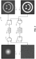
- FIG. 3 depicts one embodiment of an iterative processing system 300 (called the Gerchberg-Saxton algorithm, a description of which may be found at http://en.wikipedia.org/wiki/Gerchberg%E2%80%93Saxton_algorithm ) by which holographic data may be derived from input image data.
- Gerchberg-Saxton algorithm a description of which may be found at http://en.wikipedia.org/wiki/Gerchberg%E2%80%93Saxton_algorithm
- input image 302 is the desired image to be modeled and/or rendered by a display system.
- the holographic processing system 300 would input image data 302 into a circuit and would be placed through an inverse Fourier Transform process 306 in order to create a holographic representation 310 of the input image 302.
- holographic image 310 may appear to a human viewer as a jumbled and perhaps disordered image, it in fact captures the information content of the input image - but in the frequency domain.
- This frequency information e.g., Fourier coefficients
- the output of processing block 314 may be taken into a Fourier Transform process 316 producing the resulting 320 which is an approximation of 302.
- the difference between is 302 and 320 is calculated in processing block 304 and used to refine the image sent to 306 to reiterate the process until the error between 320 and 302 is within tolerance. Once this is achieved 310 can be used as the holographic data applied to 204.
- this process may be performed in real-time at the controller 201 based on input image data - or it may be supplied to the controller via some off-line process.
- FIG. 4 is one example, not being part of the invention, of a hologram image generator 400, as made in accordance with the principles of the present application.
- Generator 400 may comprise a laser light source 402 (or some suitable coherent or partially coherent light source).
- the light may transmit through one or more optional polarizers 404 to adjust the intensity of the light from source 402. It should be noted that this may not be a requirement of a generic system; but may provide a sort of global dimming feature.
- the light may be spread out accordingly with optical element 406. This light may then pass through a half-wave plate 408 to polarize the light as desired to be used by the polarizing beam splitter 410.
- Splitter 410 allows the polarized light from 408 to reach Spatial Light Modulator (SLM) 412 and then redirects the light reflected off 412 to 414.
- SLM 412 phase shifts the light from 408 according to the holographic data applied to it.
- Lens 414 performs an inverse Fourier transform on the phase shifted light producing the desired image at image capture 416.
- image capture 416 is shown as a camera but may also be a subsequent modulator in a multi-modulation system.
- FIG. 5A depicts one such embodiment that may employ a polarization plate (e.g., either fixed or rotatable) that affects desired beam steering as discussed herein.
- projection display system 500 may comprise a laser (or some coherent/partially coherent) light source 502, polarization recovery optics (PRO) 504, rotatable polarizer 506, beam forming/expanding lenses 508, integrating rod (or alternatively, a beam expander) 510, partial beam splitter 512a, mirror 514, MEMS array 516, lens 518, stack rod array 520, partial beam splitter 512b, and DMD array 522.
- PRO polarization recovery optics
- PRO rotatable polarizer
- beam forming/expanding lenses 508 integrating rod (or alternatively, a beam expander) 510, partial beam splitter 512a, mirror 514, MEMS array 516, lens 518, stack rod array 520, partial beam splitter 512b, and DMD array 522.
- Array 522 may serve as a second and/or additional modulator to provide additional light processing for finally projection of a final image (and possibly, through additional optical elements and/or components).
- the components from 502 to 512a may provide a light path directly to 512b - e.g., as a main beam providing substantially all of the desired illumination for the finally projected image.
- a second light path e.g., down to element 514
- a highlight illumination path that eventually may be recombined with the main beam at 512b - e.g., to provide a desired amount and placement of highlight illumination.
- FIG. 5A depicts using polarization to control the amount of uniform light directly reaching the next stage of modulation and the amount of light reaching the highlights modulator which is then sorted into discrete bins (e.g., as seen as the segments comprising 520) and that resulting non-uniform light field may be applied to the next stage of modulation.
- MEMS device 516 may be used to sort the light reaching it into discrete segments in 520.
- laser light from 502 illuminates the optical subsystem 504 and 506.
- the light illuminates rotatable polarizer 506 - which may be made to rotate under control signals from a controller (not shown).
- 506 polarizes the light from 502 and adjusts the polarization orientation relative to polarizing beam splitter 512a.
- 504 is an optional polarization recycling subsystem which may be used to improve the efficiency of the polarization.
- 510 is used to make the light more uniform such that it can be used with modulators 516 and 522.
- 512a will divert a portion of the light reaching it from 510 to 514 and the remainder to 512b. The amount of each proportion will be dependent on the polarization orientation set by 506.
- 514 is an optional fold mirror used to redirect the light from 512a to 516.
- 516 is a MEMS device with independently controllable mirrors which can divert the light reaching them to anyone of the segments of integrating rod 520. More light is diverted to segments which correspond to brighter areas of the image to be reproduced.
- 518 is a lens used to image the light reflected off the mirrors on 516 into the segmented integrating rod 520.
- 512b is used to combine the uniform light field from 512a with the typically non-uniform light field from 520 onto the next modulator 522.
- 522 modulates the combined light field from 512b to create the desired image.
- there is a projection lens system and screen following 522 similar to 112 and 114 in FIG. 1A, which are used to realize the desired image.
- the controller (not shown) analyzes the desired image to be produced and provide control to the 506, 516 and 522 to generate that image.
- 506 can be used to divert the amount of light required to establish the uniform illumination necessary at 522 to produce the image. The remaining light is routed to 516.
- Control to 516 determines how much light is directed to each segment of 520. The brighter parts of the image will have more light directed to their corresponding segments.
- the combined light field from 512b is compensated with the control sent to modulator 522 in order to create the desired image. In the case were the source 502 has more light then required either 502 can be reduced in intensity or 516 can be used to divert unused light outside of 520 so it doesn't reach 522.
- polarizer 506 may be a fixed element and the amount of light split to the highlight path may be substantially a fixed percentage of the total light - e.g., 90% to main light path and 10% to highlight light path.
- the amount of highlight light to be recombined with the main light may be controlled by allowing a desired amount of highlight light to go to a light dump - or to the highlight path and recombined with the main light path.
- FIG. 5B depicts yet another embodiment of a projector display system that may employ a non-mechanical beam steering module in the highlight light path.
- light from element 514 may be passed through a beam splitter 516b to a SLM 517b.
- This light may be holographically modulated as discussed above in reference to FIGS. 2 , 3 and 4 above.
- Lens 518b may provide a suitable Fourier transformation as previously discussed and the resulting light may provide the highlight as desired - and combined onto the main light path at beam splitter 512b.
Description
- The present invention relates to displays systems and, more particularly, to dual or multi-stage modulation projection display systems possibly employing highlight modulation.
- In a conventional multi-stage modulation projector system, there is typically a single light source that illuminates a screen with an image that is modulated by some optical system within the projector. In such conventional multi-stage modulation projector systems, it is typical that the highlights modulator is a MEMS array - or some other means of mechanical beam steering. Highlight modulators have the ability to steer the light reaching their individual steering elements to any arbitrary location in the following light path. Merely for one example, a highlights modulator may be able to steer more light onto a portion of a projected image that has a higher luminance that surrounding parts of the image - thus, that portion would be "highlighted".
- In the context of these dual/multi-modulator projector systems, it may be possible to construct such a projector system with at least one highlights modulator that may possibly employ non-mechanical beam steering that does not necessary rely on moveable mirror(s).
WO 2012/145200 discloses a projection display including a highlight projector and a main projector. Highlights projected by the highlight projector boost luminance in highlight areas of a base image projected by the main projector. - Several embodiments of display systems are herein disclosed.
- In one example, not being part of the invention, a projector display system, said display system comprising: a light source; a controller; a first holographic modulator, said first modulator being illuminated by said light source and said first modulator comprising a holographic imaging module; a lens, said lens adapted to transmit from said first holographic modulator; a second modulator, said second modulator being illuminated by light from said lens and capable of modulating light from said lens, and said second modulator comprising a plurality of mirrors; said controller further comprising: a processor; a memory, said memory associated with said processor and said memory further comprising processor-readable instructions, such that when said processor reads the processor-readable instructions, causes the processor to perform the following instructions: receiving image data; sending control signals to said first holographic modulator such that said first holographic modulator may allocate a desired proportion of the light from said light source onto said second modulator; and sending control signals to said second modulator such that said desired proportion of the light from said light source is modulated to form said desired image for projection.
- Two embodiments are disclosed by independent claims 1 and 2.
- Other features and advantages of the present system are presented below in the Detailed Description when read in connection with the drawings presented within this application.
- Exemplary embodiments are illustrated in referenced figures of the drawings. It is intended that the embodiments and figures disclosed herein are to be considered illustrative rather than restrictive.
-
FIG. 1 is one embodiment of a dual/multi-modulator projector display system that employs two moveable mirror assemblies that may take advantage of a highlights modulator. -
FIG. 2 is one example, not being part of the invention, of a dual/multi-modulator projector display system that employs a holographic imaging module as at least one non-mechanical means for steering beams of light, as made in accordance with the principles of the present application. -
FIG. 3 is one example, not being part of the invention, of a system and/or method for creating holograms for holographic imaging that affects the desired beam steering in the display system ofFIG. 2 . -
FIG. 4 is another example, not being part of the invention, of a system for creating the holographic imaging that affects the desired beam steering in the display system ofFIG. 2 . -
FIG. 5A is one embodiment of a dual/multi-modulator projector display system that may employ a polarizer to adjust the balance of light between a main light path and a highlight light path, as made in accordance with the principles of the present application. -
FIG. 5B is yet another embodiment of a dual/multi-modulator projector system that may employ a polarizer to adjust the balance of light between a main light path and a highlight light path using a non-mechanical beam steering modulator, as made in accordance with the principles of the present application - Throughout the following description, specific details are set forth in order to provide a more thorough understanding to persons skilled in the art. However, well known elements may not have been shown or described in detail to avoid unnecessarily obscuring the disclosure. Accordingly, the description and drawings are to be regarded in an illustrative, rather than a restrictive, sense.
- As utilized herein, terms "component," "system," "interface," "controller" and the like are intended to refer to a computer-related entity, either hardware, software (e.g., in execution), and/or firmware. For example, any of these terms can be a process running on a processor, a processor, an object, an executable, a program, and/or a computer. By way of illustration, both an application running on a server and the server can be a component and/or controller. One or more components/controllers can reside within a process and a component/controller can be localized on one computer and/or distributed between two or more computers.
- The claimed subject matter is described with reference to the drawings, wherein like reference numerals are used to refer to like elements throughout. In the following description, for purposes of explanation, numerous specific details are set forth in order to provide a thorough understanding of the subject innovation. It may be evident, however, that the claimed subject matter may be practiced without these specific details. In other instances, well-known structures and devices are shown in block diagram form in order to facilitate describing the subject innovation.
- Current dual/multi-modulator projector display systems comprise two or more modulation stages where illuminating light is passed in order to form a final projected image upon a projection screen. For the most part, such modulation stages comprise mechanical beam steering architectures - e.g., DMD, MEMS or some mechanically actuated set of mirrors.
FIG. 1 depicts an embodiment of a dual/multi-modulator projector display system that employs mechanical beam steering modulators. -
Projector system 100 employs alight source 102 that supplies the projector system with a desired illumination such that a final projected image will be sufficiently bright for the intended viewers of the projected image.Light source 102 may comprise any suitable light source possible - including, but not limited to: Xenon lamp, laser(s), LEDs, coherent light source, partially coherent light sources. -
Light 104 may illuminate afirst modulator 106 that may, in turn, illuminate asecond modulator 110, via a set of optionaloptical components 108. Light fromsecond modulator 110 may be projected by a projection lens 112 (or other suitable optical components) to form a final projected image upon ascreen 114. First and second modulators may be controlled by a controller 116 - which may receive input image and/or video data.Controller 116 may perform certain image processing algorithms, gamut mapping algorithms or other such suitable processing upon the input image/video data and output control/data signals to first and second modulators in order to achieve a desired final projectedimage 114. In addition, in some projector systems, it may be possible, depending on the light source, to modulate light source 102 (control line not shown) in order to achieve additional control of the image quality of the final projected image. -
First modulator 106 andsecond modulator 110 may comprise a set of mechanicallymoveable mirrors controller 116. Light may be steered by the first and second modulators as desired by such mechanical actuation. - Dual modulation projector and display systems have been described in commonly-owned patents and patent applications, including:
- (1)
United States Patent Number 8,125,702 to Ward et al., issued on February 28, 2012 and entitled "SERIAL MODULATION DISPLAY HAVING BINARY LIGHT MODULATION STAGE"; - (2)
United States Patent Application 20130148037 to Whitehead et al., published on June 13, 2013 and entitled "PROJECTION DISPLAYS"; - (3)
United States Patent Application 20110227900 to Wallener, published on September 22, 2011 and entitled "CUSTOM PSFs USING CLUSTERED LIGHT SOURCES"; - (4)
United States Patent Application 20130106923 to Shields et al., published on May 2, 2013 and entitled "SYSTEMS AND METHODS FOR ACCURATELY REPRESENTING HIGH CONTRAST IMAGERY ON HIGH DYNAMIC RANGE DISPLAY SYSTEMS"; - (5)
United States Patent Application 20110279749 to Erinjippurath et al., published on November 17, 2011 and entitled "HIGH DYNAMIC RANGE DISPLAYS USING FILTERLESS LCD(S) FOR INCREASING CONTRAST AND RESOLUTION" and - (6)
United States Patent Application 20120133689 to Kwong, published on May 31, 2012 and entitled "REFLECTORS WITH SPATIALLY VARYING REFLECTANCE/ABSORPTION GRADIENTS FOR COLOR AND LUMINANCE COMPENSATION". - In addition, there are references that disclose the use of holographic projection and the Fourier nature of the illumination to create projector display system such as:
- (1)
United States Patent Application 20140043352 to Damberg et al., published on February 13, 2014 and entitled "HIGH LUMINANCE PROJECTION DISPLAYS AND ASSOCIATED METHODS"; - (2)
United States Patent Application 20100157399 to Kroll et al., published on June 24, 2010 and entitled "HOLOGRAPHIC DISPLAY"; - (3)
United States Patent Application 20100046050 to Kroll et al., published on February 25, 2010 and entitled "COMPACT HOLOGRAPHIC DISPLAY DEVICE"; - (4)
United States Patent Application 20120008181 Cable et al., published on January 12, 2012 and entitled "HOLOGRAPHIC IMAGE DISPLAY SYSTEMS"; - (5)
United States Patent Application 20120188620 to De Echaniz et al., published on July 26, 2012 and entitled "LASER IMAGE PROJECTION SYSTEM APPLICABLE TO THE MARKING OF OBJECTS AND METHOD FOR GENERATING HOLOGRAMS" - Non-mechanical beam steering modulators, as opposed to mechanical modulators, may not have need of MEMS devices but instead leverage more common imaging devices such as LCD modulators. In particular, it may be desirable to have at least one or more modulator stages that do not comprise a moveable arrangement of mirrors.
-
FIG. 2 depicts one embodiment of a suitable projector system (200) comprising at least one non-mechanical beam steering module.Projector system 200 comprises alight source 202 that may comprise laser(s), LEDs, coherent or partially coherent light source(s) -- e.g., where the light may be of the same wavelength and phase. It suffices that, whatever light is produced fromsource 202, that light is able to sufficiently interact with a holographic image to affect the beam of the light. - Light from
source 202 illuminates firstholographic modulator 204.First modulator 204 may comprise an LCD panel or any other module that is capable of forming a holographic image thereon and interacting with the light fromsource 202.First modulator 204 may receive its holographic image from controller 201 - which, in turn, may either derive holographic data and/or control signals from input image data - or may receive holographic data from the input data stream that may accompany the input image data, if needed. As will be discussed further herein, holographic data may be derived through an iterative process that may reside inside the controller or may be sent to the controller from an outside process. - The light passing through the
first modulator 204 may illuminate a lens (and/or optical subsystem) 206.Lens 206 may affect a Fourier transformation of the illumination such that desired beam steering may be affected onto asecond modulator 208. The light fromlens 206 may be beam steered in a desired spatio-temporal fashion that allows the projector system to perform a highlight illumination of any desired feature within the projected image. For example, if there is a desired specular reflection (or any other suitable feature with higher luminance that other features) within an finally projected image, then non-mechanical beam steering employing holographic image processing is capable of steering the beam in a timely fashion to provide additional illumination to the highlight features in the finally projected image. -
Second modulator 208 may be any known modulator - e.g., DMD, MEMS and/or any set of moveable mirrors, such that the light modulated by modulator 208 (according to control signals from controller 201) may be processed byprojection lens 210 and finally projected ontoscreen 212 for viewing. - As mentioned above, the holographic data may be derived from input image data in on-board or off-line process.
FIG. 3 depicts one embodiment of an iterative processing system 300 (called the Gerchberg-Saxton algorithm, a description of which may be found at http://en.wikipedia.org/wiki/Gerchberg%E2%80%93Saxton_algorithm ) by which holographic data may be derived from input image data. - Suppose
input image 302 is the desired image to be modeled and/or rendered by a display system. Theholographic processing system 300 would inputimage data 302 into a circuit and would be placed through an inverseFourier Transform process 306 in order to create aholographic representation 310 of theinput image 302. - As may be seen,
holographic image 310 may appear to a human viewer as a jumbled and perhaps disordered image, it in fact captures the information content of the input image - but in the frequency domain. This frequency information (e.g., Fourier coefficients) may be input into a processing block 314 - together with amplitude model of the light from source 202 (312). The output ofprocessing block 314 may be taken into aFourier Transform process 316 producing the resulting 320 which is an approximation of 302. The difference between is 302 and 320 is calculated inprocessing block 304 and used to refine the image sent to 306 to reiterate the process until the error between 320 and 302 is within tolerance. Once this is achieved 310 can be used as the holographic data applied to 204. - As mentioned, this process may be performed in real-time at the
controller 201 based on input image data - or it may be supplied to the controller via some off-line process. -
FIG. 4 is one example, not being part of the invention, of ahologram image generator 400, as made in accordance with the principles of the present application.Generator 400 may comprise a laser light source 402 (or some suitable coherent or partially coherent light source). The light may transmit through one or moreoptional polarizers 404 to adjust the intensity of the light fromsource 402. It should be noted that this may not be a requirement of a generic system; but may provide a sort of global dimming feature. The light may be spread out accordingly withoptical element 406. This light may then pass through a half-wave plate 408 to polarize the light as desired to be used by thepolarizing beam splitter 410.Splitter 410 allows the polarized light from 408 to reach Spatial Light Modulator (SLM) 412 and then redirects the light reflected off 412 to 414.SLM 412 phase shifts the light from 408 according to the holographic data applied to it.Lens 414 performs an inverse Fourier transform on the phase shifted light producing the desired image atimage capture 416.image capture 416 is shown as a camera but may also be a subsequent modulator in a multi-modulation system. - Apart from holographic means of beam steering, there are other non-mechanical beam steering modules that may be suitable in a dual/multi-modulation projection display system.
- There are described in the following reference the use of a rotatable polarizer as a means to affect beam steering:
- (1)
United States Patent Application 20130265554 to BARANEC et al., published on October 10, 2013 and entitled "COMPACT LASER PROJECTION SYSTEMS AND METHODS"'; and - (2)
United States Patent Application 20120188467 to Escuti et al., published on July 26, 2012 and entitled "BEAM STEERING DEVICES INCLUDING STACKED LIQUID CRYSTAL POLARIZATION GRATINGS AND RELATED METHODS OF OPERATION" -
FIG. 5A depicts one such embodiment that may employ a polarization plate (e.g., either fixed or rotatable) that affects desired beam steering as discussed herein. In one embodiment,projection display system 500 may comprise a laser (or some coherent/partially coherent)light source 502, polarization recovery optics (PRO) 504,rotatable polarizer 506, beam forming/expandinglenses 508, integrating rod (or alternatively, a beam expander) 510,partial beam splitter 512a,mirror 514,MEMS array 516,lens 518,stack rod array 520,partial beam splitter 512b, andDMD array 522. -
Array 522 may serve as a second and/or additional modulator to provide additional light processing for finally projection of a final image (and possibly, through additional optical elements and/or components). The components from 502 to 512a may provide a light path directly to 512b - e.g., as a main beam providing substantially all of the desired illumination for the finally projected image. However, depending on polarization of the light from integrating rod(s) 510, a second light path (e.g., down to element 514) may be employed, e.g., for a highlight illumination path that eventually may be recombined with the main beam at 512b - e.g., to provide a desired amount and placement of highlight illumination. -
FIG. 5A depicts using polarization to control the amount of uniform light directly reaching the next stage of modulation and the amount of light reaching the highlights modulator which is then sorted into discrete bins (e.g., as seen as the segments comprising 520) and that resulting non-uniform light field may be applied to the next stage of modulation. As may also be seen,MEMS device 516 may be used to sort the light reaching it into discrete segments in 520. In another embodiment, it may be possible to replace 516, 518, and 520 withelements - In operation, laser light from 502 illuminates the
optical subsystem modulators rod 520. More light is diverted to segments which correspond to brighter areas of the image to be reproduced. 518 is a lens used to image the light reflected off the mirrors on 516 into the segmented integratingrod 520. 512b is used to combine the uniform light field from 512a with the typically non-uniform light field from 520 onto thenext modulator 522. 522 modulates the combined light field from 512b to create the desired image. Typically there is a projection lens system and screen following 522, similar to 112 and 114 in FIG. 1A, which are used to realize the desired image. - The controller (not shown) analyzes the desired image to be produced and provide control to the 506, 516 and 522 to generate that image. 506 can be used to divert the amount of light required to establish the uniform illumination necessary at 522 to produce the image. The remaining light is routed to 516. Control to 516 determines how much light is directed to each segment of 520. The brighter parts of the image will have more light directed to their corresponding segments. The combined light field from 512b is compensated with the control sent to
modulator 522 in order to create the desired image. In the case were thesource 502 has more light then required either 502 can be reduced in intensity or 516 can be used to divert unused light outside of 520 so it doesn't reach 522. - In another embodiment,
polarizer 506 may be a fixed element and the amount of light split to the highlight path may be substantially a fixed percentage of the total light - e.g., 90% to main light path and 10% to highlight light path. The amount of highlight light to be recombined with the main light may be controlled by allowing a desired amount of highlight light to go to a light dump - or to the highlight path and recombined with the main light path. -
FIG. 5B depicts yet another embodiment of a projector display system that may employ a non-mechanical beam steering module in the highlight light path. In this embodiment, light fromelement 514 may be passed through abeam splitter 516b to aSLM 517b. This light may be holographically modulated as discussed above in reference toFIGS. 2 ,3 and4 above.Lens 518b may provide a suitable Fourier transformation as previously discussed and the resulting light may provide the highlight as desired - and combined onto the main light path atbeam splitter 512b. - A detailed description of one or more embodiments of the invention, read along with accompanying figures, that illustrate the principles of the invention has now been given. It is to be appreciated that the invention is described in connection with such embodiments, but the invention is not limited to any embodiment. The scope of the invention is limited only by the claims. Numerous specific details have been set forth in this description in order to provide a thorough understanding of the invention. These details are provided for the purpose of example and the invention may be practiced according to the claims without some or all of these specific details. For the purpose of clarity, technical material that is known in the technical fields related to the invention has not been described in detail so that the invention is not unnecessarily obscured.
Claims (9)
- A projector display system, said display system comprising:a light source (502);a polarizer (506) configured to induce a polarization to light received from said light source;polarizing beam splitter (512a) configured to, based upon said polarization induced by said polarizer, split the light between first light propagating along a main light path and second light propagating along a highlight path;a spatial light modulator (516) configured to modulate said second light to create highlight light; anda partial beam splitter (512b) configured to combine said highlight light with said first light,wherein said polarizer (506) is a rotatable polarizer, and the display system further comprises a controller configured to send control signals to said rotatable polarizer to control an amount of second light to be split to said highlight path from said main light path.
- A projector display system, said display system comprising:a light source (502);a polarizer (506) configured to induce a polarization to light received from said light source;polarizing beam splitter (512a) configured to, based upon said polarization induced by said polarizer, split the light between first light propagating along a main light path and second light propagating along a highlight path;a spatial light modulator (516) configured to modulate said second light to create highlight light; anda partial beam splitter (512b) configured to combine said highlight light with said first light,wherein said polarizer (506) is a fixed polarizer, and the display system further comprises a controller configured to send control signals to said spatial light modulator to control an amount of highlight light to be combined with said first light.
- The display system of Claim 1 or 2,
the controller including:a processor, anda memory associated with said processor and comprising processor-readable instructions that, when said processor reads said processor-readable instructions, causes said processor to perform the following functions:(a) receiving image data including at least one highlight feature, and(b) commanding said spatial light modulator to modulate said second light to create said highlight light. - The display system of Claim 1 or 2, wherein said spatial light modulator further comprises a MEMS array (516) and an integrating rod (520).
- The display system of Claim 4, wherein said MEMS array is configured to spatially modulate said second light and steer said second light to said integrating rod to affect said highlight light to be combined with said first light.
- The display system of Claim 1 or 2, wherein said spatial light modulator further comprises a second partial beam splitter (516b), a holographic Spatial Light Modulator, SLM, (517b) and a lens (518b).
- The display system of Claim 6, further comprising a controller configured to send signals to said holographic SLM to modulate said second light to form said highlight light.
- The display system of Claim 1 or 2, further comprising polarization recovery optics (504) placed before said polarizer.
- The display system of Claim 1 or 2, further comprising a beam expander (510) positioned between said polarizer and said polarizing beam splitter.
Priority Applications (1)
| Application Number | Priority Date | Filing Date | Title |
|---|---|---|---|
| EP23206163.0A EP4294004A3 (en) | 2013-07-30 | 2014-07-28 | Projector display systems having non-mechanical mirror beam steering |
Applications Claiming Priority (4)
| Application Number | Priority Date | Filing Date | Title |
|---|---|---|---|
| US201361860203P | 2013-07-30 | 2013-07-30 | |
| US201461979248P | 2014-04-14 | 2014-04-14 | |
| PCT/US2014/048479 WO2015017346A1 (en) | 2013-07-30 | 2014-07-28 | Projector display systems having non-mechanical mirror beam steering |
| EP14833035.0A EP3028099B1 (en) | 2013-07-30 | 2014-07-28 | Projector display systems having non-mechanical mirror beam steering |
Related Parent Applications (1)
| Application Number | Title | Priority Date | Filing Date |
|---|---|---|---|
| EP14833035.0A Division EP3028099B1 (en) | 2013-07-30 | 2014-07-28 | Projector display systems having non-mechanical mirror beam steering |
Related Child Applications (1)
| Application Number | Title | Priority Date | Filing Date |
|---|---|---|---|
| EP23206163.0A Division EP4294004A3 (en) | 2013-07-30 | 2014-07-28 | Projector display systems having non-mechanical mirror beam steering |
Publications (3)
| Publication Number | Publication Date |
|---|---|
| EP3667412A2 EP3667412A2 (en) | 2020-06-17 |
| EP3667412A3 EP3667412A3 (en) | 2020-09-23 |
| EP3667412B1 true EP3667412B1 (en) | 2023-11-01 |
Family
ID=52432363
Family Applications (3)
| Application Number | Title | Priority Date | Filing Date |
|---|---|---|---|
| EP23206163.0A Pending EP4294004A3 (en) | 2013-07-30 | 2014-07-28 | Projector display systems having non-mechanical mirror beam steering |
| EP14833035.0A Active EP3028099B1 (en) | 2013-07-30 | 2014-07-28 | Projector display systems having non-mechanical mirror beam steering |
| EP19211732.3A Active EP3667412B1 (en) | 2013-07-30 | 2014-07-28 | Projector display systems having non-mechanical mirror beam steering |
Family Applications Before (2)
| Application Number | Title | Priority Date | Filing Date |
|---|---|---|---|
| EP23206163.0A Pending EP4294004A3 (en) | 2013-07-30 | 2014-07-28 | Projector display systems having non-mechanical mirror beam steering |
| EP14833035.0A Active EP3028099B1 (en) | 2013-07-30 | 2014-07-28 | Projector display systems having non-mechanical mirror beam steering |
Country Status (11)
| Country | Link |
|---|---|
| US (5) | US9983545B2 (en) |
| EP (3) | EP4294004A3 (en) |
| JP (5) | JP6286546B2 (en) |
| CN (2) | CN107632486B (en) |
| BR (2) | BR122020013722B1 (en) |
| ES (2) | ES2768699T3 (en) |
| HK (1) | HK1221288A1 (en) |
| MY (1) | MY177315A (en) |
| PL (1) | PL3028099T3 (en) |
| RU (2) | RU2654899C2 (en) |
| WO (1) | WO2015017346A1 (en) |
Families Citing this family (18)
| Publication number | Priority date | Publication date | Assignee | Title |
|---|---|---|---|---|
| BR122020013722B1 (en) * | 2013-07-30 | 2022-12-27 | Dolby Laboratories Licensing Corporation | PROJECTOR DISPLAY SYSTEM HAVING NON-MECHANICAL MIRROR BEAM DIRECTION |
| PL3066829T3 (en) | 2013-11-04 | 2021-03-08 | Dolby Laboratories Licensing Corporation | Single and multi-modulator projector systems with global dimming |
| US10757382B2 (en) * | 2014-12-18 | 2020-08-25 | Nec Corporation | Projection apparatus and interface apparatus |
| US10386709B2 (en) | 2014-12-31 | 2019-08-20 | Dolby Laboratories Licensing Corporation | Methods and systems for high dynamic range image projectors |
| CN108141574B (en) * | 2015-10-06 | 2021-07-27 | Mtt创新公司 | Method, control system and device for projecting a color image |
| EP4120678A1 (en) | 2016-09-30 | 2023-01-18 | Dolby Laboratories Licensing Corporation | Beam combining for highlight projection |
| US10948735B2 (en) * | 2017-02-03 | 2021-03-16 | Barco N.V. | System and method for enhanced image projection |
| JP6926526B2 (en) * | 2017-02-28 | 2021-08-25 | セイコーエプソン株式会社 | projector |
| WO2018205036A1 (en) * | 2017-05-12 | 2018-11-15 | Mtt Innovation Incorporated | High brightness projection systems and methods |
| US10416539B2 (en) * | 2017-06-21 | 2019-09-17 | Dolby Laboratories Licensing Corporation | Spatial light modulator for reduction of certain order light |
| US10488746B2 (en) * | 2017-11-14 | 2019-11-26 | Dolby Laboratories Licensing Corporation | Aperture sharing for highlight projection |
| CN112930680A (en) | 2018-09-26 | 2021-06-08 | 杜比实验室特许公司 | Projector light source dimming using metadata from future frames |
| JP2020112674A (en) * | 2019-01-11 | 2020-07-27 | ソニーセミコンダクタソリューションズ株式会社 | Display device and method for adjusting display device |
| US20220060668A1 (en) * | 2019-02-22 | 2022-02-24 | President And Fellows Of Harvard College | Large-scale uniform optical focus array generation with a phase spatial light modulator |
| US20220191440A1 (en) * | 2019-03-15 | 2022-06-16 | Dolby Laboratories Licensing Corporation | Dual-modulation laser projection systems and methods |
| US10880528B1 (en) * | 2019-10-31 | 2020-12-29 | Christie Digital Systems Usa, Inc. | Device, system and method for modulating light using a phase light modulator and a spatial light modulator |
| GB2610203A (en) * | 2021-08-26 | 2023-03-01 | Envisics Ltd | Hologram calculation |
| WO2024024414A1 (en) * | 2022-07-26 | 2024-02-01 | 株式会社フジクラ | Optical computation device |
Citations (18)
| Publication number | Priority date | Publication date | Assignee | Title |
|---|---|---|---|---|
| GB2499979A (en) * | 2012-01-20 | 2013-09-11 | Light Blue Optics Ltd | Touch-sensitive image display devices |
| GB2500364A (en) * | 2012-01-30 | 2013-09-25 | Light Blue Optics Ltd | Image projection using wavelength conversion |
| NL2010215A (en) * | 2012-03-29 | 2013-10-01 | Asml Holding Nv | Compact self-contained holographic and interferometric apparatus. |
| GB2509180A (en) * | 2012-12-21 | 2014-06-25 | Two Trees Photonics Ltd | Holographic projector |
| GB2515460A (en) * | 2013-04-12 | 2014-12-31 | Two Trees Photonics Ltd | Near-eye device |
| GB2518664A (en) * | 2013-09-27 | 2015-04-01 | Two Trees Photonics Ltd | Projector |
| DE102015110502A1 (en) * | 2014-07-04 | 2016-01-07 | Seereal Technologies S.A. | Projection apparatus and method for displaying a two-dimensional and / or three-dimensional scene or content |
| NL2015160A (en) * | 2014-07-28 | 2016-07-07 | Asml Netherlands Bv | Illumination system, inspection apparatus including such an illumination system, inspection method and manufacturing method. |
| DE112015000351T5 (en) * | 2014-01-07 | 2016-10-27 | Seereal Technologies S.A. | Display device for a holographic reconstruction |
| DE202013012664U1 (en) * | 2012-02-07 | 2018-05-11 | Envisics Ltd. | lighting device |
| ES2670608T3 (en) * | 2013-12-10 | 2018-05-31 | Dolby Laboratories Licensing Corp. | Acoustic-optical beam direction modulator for a projection system |
| ES2688819T3 (en) * | 2012-04-13 | 2018-11-07 | Red.Com, Llc | Video projector system |
| PL3161557T3 (en) * | 2014-06-27 | 2020-04-30 | Dolby Laboratories Licensing Corporation | Light recycling for projectors with high dynamic range |
| PL3028099T3 (en) * | 2013-07-30 | 2020-05-18 | Dolby Laboratories Licensing Corporation | Projector display systems having non-mechanical mirror beam steering |
| PL3055993T3 (en) * | 2013-10-10 | 2020-07-13 | Dolby Laboratories Licensing Corp. | Displaying dci and other content on an enhanced dynamic range projector |
| PL3066829T3 (en) * | 2013-11-04 | 2021-03-08 | Dolby Laboratories Licensing Corporation | Single and multi-modulator projector systems with global dimming |
| ES2827450T3 (en) * | 2013-11-03 | 2021-05-21 | Dolby Laboratories Licensing Corp | System and method for local dimming in multi-modulation screens |
| ES2880740T3 (en) * | 2013-05-07 | 2021-11-25 | Dolby Laboratories Licensing Corp | Multiple halftone imaging and dual modulation projection / dual modulation laser projection |
Family Cites Families (94)
| Publication number | Priority date | Publication date | Assignee | Title |
|---|---|---|---|---|
| CA2084923A1 (en) * | 1991-12-20 | 1993-06-21 | Ronald E. Stafford | Slm spectrometer |
| WO1994009473A1 (en) | 1992-10-15 | 1994-04-28 | Rank Brimar Limited | Display device |
| US5428417A (en) * | 1993-08-02 | 1995-06-27 | Lichtenstein; Bernard | Visual lecture aid |
| JPH08294138A (en) * | 1995-04-21 | 1996-11-05 | Mitsubishi Electric Corp | Liquid crystal projector |
| JP3521113B2 (en) * | 1998-03-27 | 2004-04-19 | パイオニア株式会社 | Volume holographic memory optical information recording / reproducing apparatus |
| US6897999B1 (en) * | 1998-11-25 | 2005-05-24 | The Research Foundation Of The University Of Central Florida | Optically written display |
| JP3611757B2 (en) * | 1999-08-31 | 2005-01-19 | パイオニア株式会社 | Two-color hologram recording / reproducing device |
| JP3611756B2 (en) * | 1999-08-31 | 2005-01-19 | パイオニア株式会社 | Hologram recording apparatus and method thereof |
| JP2001184637A (en) * | 1999-12-28 | 2001-07-06 | Pioneer Electronic Corp | Optical information recording and reproducing device |
| WO2002003687A2 (en) | 2000-07-03 | 2002-01-10 | Imax Corporation | Equipment and techniques for increasing the dynamic range of a projection system |
| US6337760B1 (en) | 2000-07-17 | 2002-01-08 | Reflectivity, Inc. | Encapsulated multi-directional light beam steering device |
| EP2312380B1 (en) | 2001-02-27 | 2020-11-18 | Dolby Laboratories Licensing Corporation | A method and device for displaying an image |
| US6863401B2 (en) * | 2001-06-30 | 2005-03-08 | Texas Instruments Incorporated | Illumination system |
| JP4348457B2 (en) * | 2002-03-13 | 2009-10-21 | ドルビー ラボラトリーズ ライセンシング コーポレイション | High dynamic range display, display controller, and image display method |
| JP2004069722A (en) * | 2002-08-01 | 2004-03-04 | Pioneer Electronic Corp | Hologram recording and reproducing system |
| JP2004069771A (en) * | 2002-08-01 | 2004-03-04 | Pioneer Electronic Corp | Hologram system |
| US6850352B1 (en) | 2004-01-08 | 2005-02-01 | Hewlett-Packard Development Company, L.P. | Method and system for generating color using a low-resolution spatial color modulator and a high-resolution modulator |
| JP2005241905A (en) * | 2004-02-26 | 2005-09-08 | Nikon Corp | Projection type display device |
| JP4289269B2 (en) | 2004-03-01 | 2009-07-01 | セイコーエプソン株式会社 | Optical display device, optical display device control program, and optical display device control method |
| KR101159495B1 (en) * | 2004-03-11 | 2012-06-22 | 이코스비젼 시스팀스 엔.브이. | Methods and apparatus for wavefront manipulations and improved 3-d measurements |
| CN1961263A (en) * | 2004-03-31 | 2007-05-09 | 先锋株式会社 | Hologram reproduction device and hologram reproduction method |
| WO2005099386A2 (en) * | 2004-04-13 | 2005-10-27 | Board Of Regents, The University Of Texas System | Holographic projector |
| CN100488229C (en) * | 2004-05-03 | 2009-05-13 | 不列颠哥伦比亚大学 | Method for efficient computation of image frames for dual modulation display systems using key frames |
| JP4151609B2 (en) * | 2004-05-19 | 2008-09-17 | セイコーエプソン株式会社 | Lighting device, display device, projector |
| US8217970B2 (en) * | 2004-07-27 | 2012-07-10 | Dolby Laboratories Licensing Corporation | Rapid image rendering on dual-modulator displays |
| US20060092380A1 (en) * | 2004-11-04 | 2006-05-04 | Salsman Kenneth E | Clean-up polarizer and gamma control for display system |
| JP2006208923A (en) * | 2005-01-31 | 2006-08-10 | Seiko Epson Corp | Stereoscopic image display device |
| US7346234B2 (en) | 2005-04-11 | 2008-03-18 | Capella Photonics | Reduction of MEMS mirror edge diffraction in a wavelength selective switch using servo-based multi-axes rotation |
| GB0512179D0 (en) | 2005-06-15 | 2005-07-20 | Light Blue Optics Ltd | Holographic dispaly devices |
| CN101203802B (en) * | 2005-06-20 | 2010-05-19 | 松下电器产业株式会社 | 2-dimensional image display device, illumination light source, and exposure illumination device |
| US7651227B2 (en) * | 2005-09-13 | 2010-01-26 | Texas Instruments Incorporated | Projection system and method including spatial light modulator and compact diffractive optics |
| US20070120786A1 (en) | 2005-11-28 | 2007-05-31 | Texas Instruments Incorporated | Sequence design in a display system |
| US7511867B2 (en) * | 2005-12-26 | 2009-03-31 | Fuji Xerox Co., Ltd. | Hologram reproduction method and apparatus |
| KR100796766B1 (en) * | 2006-05-29 | 2008-01-22 | (주)레드로버 | Construction of stereo optical engine for projection |
| JP2008033021A (en) * | 2006-07-28 | 2008-02-14 | Fuji Xerox Co Ltd | Hologram recording method and hologram recording device |
| JP4957162B2 (en) * | 2006-10-06 | 2012-06-20 | セイコーエプソン株式会社 | Projection display device and projection display method |
| EP2084579A1 (en) | 2006-10-26 | 2009-08-05 | SeeReal Technologies S.A. | Compact holographic display device |
| WO2008058142A1 (en) * | 2006-11-06 | 2008-05-15 | University Of Massachusetts | Systems and methods of all-optical fourier phase contrast imaging using dye doped liquid crystals |
| JP2008191472A (en) * | 2007-02-06 | 2008-08-21 | Sony Corp | Three-dimensional image display system |
| KR20080073464A (en) | 2007-02-06 | 2008-08-11 | 삼성전자주식회사 | Apparatus for driving of light source and display device having the same and method of the driving |
| GB2446617A (en) * | 2007-02-16 | 2008-08-20 | Indepth Optics Ltd | 3D holographic display |
| US7961161B2 (en) * | 2007-03-02 | 2011-06-14 | Silicon Quest Kabushiki-Kaisha | Display system comprising a mirror device with micromirrors controlled to operate in intermediate oscillating state |
| JP5312748B2 (en) * | 2007-03-02 | 2013-10-09 | オリンパス株式会社 | Holographic projection method and holographic projection apparatus |
| US20080231936A1 (en) * | 2007-03-02 | 2008-09-25 | Taro Endo | Display system comprising a mirror device with micromirrors controlled to operate in intermediate oscillating state |
| DE102007013431B4 (en) * | 2007-03-15 | 2018-07-05 | Seereal Technologies S.A. | Method and apparatus for reconstructing a three-dimensional scene with corrected visibility |
| US7812959B1 (en) * | 2007-03-22 | 2010-10-12 | University Of South Florida | Total internal reflection holographic microscope |
| GB2448132B (en) * | 2007-03-30 | 2012-10-10 | Light Blue Optics Ltd | Optical Systems |
| US20080246705A1 (en) | 2007-04-03 | 2008-10-09 | Texas Instruments Incorporated | Off-state light recapturing in display systems employing spatial light modulators |
| DE102007018266A1 (en) * | 2007-04-10 | 2008-10-16 | Seereal Technologies S.A. | Holographic projection system with optical waveguide tracking and means for correcting the holographic reconstruction |
| US8218211B2 (en) | 2007-05-16 | 2012-07-10 | Seereal Technologies S.A. | Holographic display with a variable beam deflection |
| GB0718626D0 (en) * | 2007-05-16 | 2007-11-07 | Seereal Technologies Sa | Holograms |
| US7986603B1 (en) * | 2007-09-29 | 2011-07-26 | Silicon Light Machines Corporation | Spatial light modulator for holographic data storage |
| GB0719721D0 (en) * | 2007-10-09 | 2007-11-21 | Seos Ltd | Image display apparatus |
| GB2454246B (en) * | 2007-11-02 | 2010-03-10 | Light Blue Optics Ltd | Holographic image display systems |
| US8446349B2 (en) | 2007-11-27 | 2013-05-21 | Texas Instruments Incorporated | Method and system for controlling deformable micromirror devices |
| US20090141187A1 (en) * | 2007-12-04 | 2009-06-04 | Akira Shirai | Buffer Management system for video image display apparatus |
| US20090141194A1 (en) * | 2007-12-04 | 2009-06-04 | Akira Shirai | Apparatus and method, both for controlling spatial light modulator |
| US7551341B1 (en) * | 2008-01-28 | 2009-06-23 | Dolby Laboratories Licensing Corporation | Serial modulation display having binary light modulation stage |
| US8157388B2 (en) * | 2008-03-31 | 2012-04-17 | Texas Instruments Incorporated | System and method for a projection display system using an optical lightguide |
| US8134591B2 (en) * | 2008-05-07 | 2012-03-13 | Eastman Kodak Company | Display using bidirectionally scanned linear modulator |
| DE102009002987B4 (en) * | 2008-05-16 | 2018-11-08 | Seereal Technologies S.A. | Controllable device for phase modulation |
| GB2461894B (en) * | 2008-07-16 | 2010-06-23 | Light Blue Optics Ltd | Holographic image display systems |
| JP4539766B2 (en) * | 2008-08-13 | 2010-09-08 | ソニー株式会社 | Hologram recording / reproducing apparatus, hologram recording / reproducing method, and hologram recording medium |
| US8531492B2 (en) | 2008-11-14 | 2013-09-10 | Dolby Laboratories Licensing Corporation | Custom PSFs using clustered light sources |
| JP5122432B2 (en) * | 2008-12-16 | 2013-01-16 | 株式会社Jvcケンウッド | Optical system and projection display device |
| GB2466497B (en) * | 2008-12-24 | 2011-09-14 | Light Blue Optics Ltd | Touch sensitive holographic displays |
| CN102292761B (en) * | 2009-01-21 | 2014-03-05 | 杜比实验室特许公司 | Apparatus and methods for color displays |
| US20100214282A1 (en) * | 2009-02-24 | 2010-08-26 | Dolby Laboratories Licensing Corporation | Apparatus for providing light source modulation in dual modulator displays |
| GB2468911A (en) | 2009-03-27 | 2010-09-29 | Light Blue Optics Ltd | Aberration correction methods using wavefront sensing hologram patches and mapping of phase aberration corrections |
| US8797382B2 (en) * | 2009-04-13 | 2014-08-05 | Hewlett-Packard Development Company, L.P. | Dynamically reconfigurable holograms for generating color holographic images |
| GB0907297D0 (en) * | 2009-04-29 | 2009-06-10 | Light Blue Optics Ltd | Dynamic backlighting |
| ES2393896B1 (en) | 2009-06-10 | 2013-11-11 | Easy Laser S.L. | LASER IMAGE PROJECTION SYSTEM APPLICABLE TO THE MARKING OF OBJECTS AND METHOD FOR THE GENERATION OF HOLOGRAMS. |
| US8982313B2 (en) | 2009-07-31 | 2015-03-17 | North Carolina State University | Beam steering devices including stacked liquid crystal polarization gratings and related methods of operation |
| US8890905B2 (en) | 2009-08-18 | 2014-11-18 | Dolby Laboratories Licensing Corporation | Reflectors with spatially varying reflectance/absorption gradients for color and luminance compensation |
| WO2011025724A1 (en) * | 2009-08-27 | 2011-03-03 | Dolby Laboratories Licensing Corporation | Optical mixing and shaping system for display backlights and displays incorporating the same |
| US8199387B1 (en) * | 2009-09-14 | 2012-06-12 | Physical Optics Corporation | Phase addressed holographic associative memory |
| US9864243B2 (en) | 2010-05-14 | 2018-01-09 | Dolby Laboratories Licensing Corporation | High dynamic range displays using filterless LCD(s) for increasing contrast and resolution |
| US9135864B2 (en) | 2010-05-14 | 2015-09-15 | Dolby Laboratories Licensing Corporation | Systems and methods for accurately representing high contrast imagery on high dynamic range display systems |
| WO2012002207A1 (en) * | 2010-06-29 | 2012-01-05 | 国立大学法人京都工芸繊維大学 | Method and apparatus for polarization imaging |
| EP3404452B1 (en) * | 2010-09-07 | 2020-10-28 | Dai Nippon Printing Co., Ltd. | Projection type image display apparatus and corresponding method |
| JP2012088451A (en) * | 2010-10-18 | 2012-05-10 | Sony Corp | Lighting device and display device |
| EP2631909B1 (en) * | 2010-10-19 | 2019-09-25 | National University Corporation Hokkaido University | Holographic memory reproduction device and holographic memory reproduction method |
| KR101766272B1 (en) * | 2010-11-01 | 2017-08-08 | 삼성전자주식회사 | Apparatus and method for displaying holographic image using collimated directional backlight unit |
| GB2555332B (en) | 2010-11-22 | 2018-07-11 | Dualitas Ltd | Holographic systems |
| EP2712037A3 (en) | 2011-02-25 | 2014-06-18 | Barret Lippey | Laser display method and system |
| CN102918431A (en) * | 2011-04-12 | 2013-02-06 | 松下电器产业株式会社 | Incoherence device and optical apparatus using same |
| US20140043352A1 (en) * | 2011-04-19 | 2014-02-13 | Dolby Laboratories Licensing Corporation | High Luminance Projection Displays And Associated Methods |
| WO2013094011A1 (en) | 2011-12-20 | 2013-06-27 | Necディスプレイソリューションズ株式会社 | Image projection device and control method for same |
| US8783874B1 (en) * | 2012-01-18 | 2014-07-22 | Nusensors, Inc. | Compressive optical display and imager |
| US9753284B2 (en) * | 2012-01-24 | 2017-09-05 | Sony Corporation | Display device |
| US9279977B2 (en) | 2012-04-10 | 2016-03-08 | California Institute Of Technology | Compact laser projection systems and methods |
| CN102749793B (en) * | 2012-07-24 | 2014-06-11 | 东南大学 | Holographic projection method |
| US9049413B2 (en) | 2013-07-30 | 2015-06-02 | Dolby Laboratories Licensing Corporation | Multiple stage modulation projector display systems having efficient light utilization |
| CN106557004A (en) * | 2015-09-28 | 2017-04-05 | 中兴通讯股份有限公司 | A kind of holographic projection methods and device |
-
2014
- 2014-07-28 BR BR122020013722-3A patent/BR122020013722B1/en active IP Right Grant
- 2014-07-28 RU RU2016102198A patent/RU2654899C2/en active
- 2014-07-28 CN CN201710749952.7A patent/CN107632486B/en active Active
- 2014-07-28 WO PCT/US2014/048479 patent/WO2015017346A1/en active Application Filing
- 2014-07-28 US US14/904,946 patent/US9983545B2/en active Active
- 2014-07-28 BR BR112016001699-8A patent/BR112016001699B1/en active IP Right Grant
- 2014-07-28 CN CN201480043286.XA patent/CN105452955B/en active Active
- 2014-07-28 JP JP2016531800A patent/JP6286546B2/en active Active
- 2014-07-28 EP EP23206163.0A patent/EP4294004A3/en active Pending
- 2014-07-28 MY MYPI2016700037A patent/MY177315A/en unknown
- 2014-07-28 ES ES14833035T patent/ES2768699T3/en active Active
- 2014-07-28 EP EP14833035.0A patent/EP3028099B1/en active Active
- 2014-07-28 PL PL14833035T patent/PL3028099T3/en unknown
- 2014-07-28 EP EP19211732.3A patent/EP3667412B1/en active Active
- 2014-07-28 ES ES19211732T patent/ES2965929T3/en active Active
-
2016
- 2016-08-05 HK HK16109343.7A patent/HK1221288A1/en unknown
-
2017
- 2017-10-23 JP JP2017204355A patent/JP6425787B2/en active Active
-
2018
- 2018-04-20 RU RU2018114637A patent/RU2763466C2/en active
- 2018-04-23 US US15/960,099 patent/US10534316B2/en active Active
- 2018-10-23 JP JP2018199479A patent/JP6845203B2/en active Active
-
2019
- 2019-12-11 US US16/710,691 patent/US10969742B2/en active Active
-
2020
- 2020-12-09 JP JP2020204347A patent/JP7082655B2/en active Active
-
2021
- 2021-04-05 US US17/222,637 patent/US11592783B2/en active Active
-
2022
- 2022-05-27 JP JP2022086838A patent/JP2022119911A/en active Pending
-
2023
- 2023-01-26 US US18/160,177 patent/US20230168626A1/en active Pending
Patent Citations (18)
| Publication number | Priority date | Publication date | Assignee | Title |
|---|---|---|---|---|
| GB2499979A (en) * | 2012-01-20 | 2013-09-11 | Light Blue Optics Ltd | Touch-sensitive image display devices |
| GB2500364A (en) * | 2012-01-30 | 2013-09-25 | Light Blue Optics Ltd | Image projection using wavelength conversion |
| DE202013012664U1 (en) * | 2012-02-07 | 2018-05-11 | Envisics Ltd. | lighting device |
| NL2010215A (en) * | 2012-03-29 | 2013-10-01 | Asml Holding Nv | Compact self-contained holographic and interferometric apparatus. |
| ES2688819T3 (en) * | 2012-04-13 | 2018-11-07 | Red.Com, Llc | Video projector system |
| GB2509180A (en) * | 2012-12-21 | 2014-06-25 | Two Trees Photonics Ltd | Holographic projector |
| GB2515460A (en) * | 2013-04-12 | 2014-12-31 | Two Trees Photonics Ltd | Near-eye device |
| ES2880740T3 (en) * | 2013-05-07 | 2021-11-25 | Dolby Laboratories Licensing Corp | Multiple halftone imaging and dual modulation projection / dual modulation laser projection |
| PL3028099T3 (en) * | 2013-07-30 | 2020-05-18 | Dolby Laboratories Licensing Corporation | Projector display systems having non-mechanical mirror beam steering |
| GB2518664A (en) * | 2013-09-27 | 2015-04-01 | Two Trees Photonics Ltd | Projector |
| PL3055993T3 (en) * | 2013-10-10 | 2020-07-13 | Dolby Laboratories Licensing Corp. | Displaying dci and other content on an enhanced dynamic range projector |
| ES2827450T3 (en) * | 2013-11-03 | 2021-05-21 | Dolby Laboratories Licensing Corp | System and method for local dimming in multi-modulation screens |
| PL3066829T3 (en) * | 2013-11-04 | 2021-03-08 | Dolby Laboratories Licensing Corporation | Single and multi-modulator projector systems with global dimming |
| ES2670608T3 (en) * | 2013-12-10 | 2018-05-31 | Dolby Laboratories Licensing Corp. | Acoustic-optical beam direction modulator for a projection system |
| DE112015000351T5 (en) * | 2014-01-07 | 2016-10-27 | Seereal Technologies S.A. | Display device for a holographic reconstruction |
| PL3161557T3 (en) * | 2014-06-27 | 2020-04-30 | Dolby Laboratories Licensing Corporation | Light recycling for projectors with high dynamic range |
| DE102015110502A1 (en) * | 2014-07-04 | 2016-01-07 | Seereal Technologies S.A. | Projection apparatus and method for displaying a two-dimensional and / or three-dimensional scene or content |
| NL2015160A (en) * | 2014-07-28 | 2016-07-07 | Asml Netherlands Bv | Illumination system, inspection apparatus including such an illumination system, inspection method and manufacturing method. |
Also Published As
Similar Documents
| Publication | Publication Date | Title |
|---|---|---|
| US11592783B2 (en) | Projector display systems having non-mechanical mirror beam steering | |
| JP6473472B2 (en) | Holographic image projection using holographic correction | |
| KR102470414B1 (en) | Pulpil expander | |
| CN108957746B (en) | Near-to-eye device | |
| KR102575669B1 (en) | Projection | |
| EP3080663B1 (en) | Acousto-optic beam steering modulator for a projection system | |
| US20240036333A1 (en) | Increasing the field of view of near-eye displays | |
| Makowski et al. | Real-Time Lensless Image Projection by Electroholography with Amplitude-Phase Modulation |
Legal Events
| Date | Code | Title | Description |
|---|---|---|---|
| PUAI | Public reference made under article 153(3) epc to a published international application that has entered the european phase |
Free format text: ORIGINAL CODE: 0009012 |
|
| STAA | Information on the status of an ep patent application or granted ep patent |
Free format text: STATUS: THE APPLICATION HAS BEEN PUBLISHED |
|
| AC | Divisional application: reference to earlier application |
Ref document number: 3028099 Country of ref document: EP Kind code of ref document: P |
|
| AK | Designated contracting states |
Kind code of ref document: A2 Designated state(s): AL AT BE BG CH CY CZ DE DK EE ES FI FR GB GR HR HU IE IS IT LI LT LU LV MC MK MT NL NO PL PT RO RS SE SI SK SM TR |
|
| PUAL | Search report despatched |
Free format text: ORIGINAL CODE: 0009013 |
|
| RIC1 | Information provided on ipc code assigned before grant |
Ipc: H04N 9/31 20060101ALI20200718BHEP Ipc: G03H 1/22 20060101ALI20200718BHEP Ipc: G02B 26/02 20060101ALI20200718BHEP Ipc: G03B 21/28 20060101AFI20200718BHEP Ipc: G03B 21/20 20060101ALI20200718BHEP Ipc: G03H 1/08 20060101ALI20200718BHEP Ipc: G02B 27/09 20060101ALI20200718BHEP Ipc: G02B 27/10 20060101ALI20200718BHEP Ipc: G03H 1/00 20060101ALI20200718BHEP Ipc: G02B 27/28 20060101ALI20200718BHEP Ipc: G02B 26/08 20060101ALI20200718BHEP Ipc: G02B 5/30 20060101ALI20200718BHEP |
|
| AK | Designated contracting states |
Kind code of ref document: A3 Designated state(s): AL AT BE BG CH CY CZ DE DK EE ES FI FR GB GR HR HU IE IS IT LI LT LU LV MC MK MT NL NO PL PT RO RS SE SI SK SM TR |
|
| RIC1 | Information provided on ipc code assigned before grant |
Ipc: G02B 27/28 20060101ALI20200814BHEP Ipc: G02B 27/10 20060101ALI20200814BHEP Ipc: G03B 21/28 20060101AFI20200814BHEP Ipc: G03H 1/08 20060101ALI20200814BHEP Ipc: G02B 27/09 20060101ALI20200814BHEP Ipc: G03H 1/00 20060101ALI20200814BHEP Ipc: G03B 21/20 20060101ALI20200814BHEP Ipc: G02B 5/30 20060101ALI20200814BHEP Ipc: G03H 1/22 20060101ALI20200814BHEP Ipc: H04N 9/31 20060101ALI20200814BHEP Ipc: G02B 26/08 20060101ALI20200814BHEP Ipc: G02B 26/02 20060101ALI20200814BHEP |
|
| STAA | Information on the status of an ep patent application or granted ep patent |
Free format text: STATUS: REQUEST FOR EXAMINATION WAS MADE |
|
| 17P | Request for examination filed |
Effective date: 20210323 |
|
| RBV | Designated contracting states (corrected) |
Designated state(s): AL AT BE BG CH CY CZ DE DK EE ES FI FR GB GR HR HU IE IS IT LI LT LU LV MC MK MT NL NO PL PT RO RS SE SI SK SM TR |
|
| GRAP | Despatch of communication of intention to grant a patent |
Free format text: ORIGINAL CODE: EPIDOSNIGR1 |
|
| STAA | Information on the status of an ep patent application or granted ep patent |
Free format text: STATUS: GRANT OF PATENT IS INTENDED |
|
| INTG | Intention to grant announced |
Effective date: 20221026 |
|
| GRAJ | Information related to disapproval of communication of intention to grant by the applicant or resumption of examination proceedings by the epo deleted |
Free format text: ORIGINAL CODE: EPIDOSDIGR1 |
|
| STAA | Information on the status of an ep patent application or granted ep patent |
Free format text: STATUS: REQUEST FOR EXAMINATION WAS MADE |
|
| RAP3 | Party data changed (applicant data changed or rights of an application transferred) |
Owner name: DOLBY LABORATORIES LICENSING CORPORATION |
|
| INTC | Intention to grant announced (deleted) | ||
| GRAP | Despatch of communication of intention to grant a patent |
Free format text: ORIGINAL CODE: EPIDOSNIGR1 |
|
| STAA | Information on the status of an ep patent application or granted ep patent |
Free format text: STATUS: GRANT OF PATENT IS INTENDED |
|
| GRAJ | Information related to disapproval of communication of intention to grant by the applicant or resumption of examination proceedings by the epo deleted |
Free format text: ORIGINAL CODE: EPIDOSDIGR1 |
|
| GRAJ | Information related to disapproval of communication of intention to grant by the applicant or resumption of examination proceedings by the epo deleted |
Free format text: ORIGINAL CODE: EPIDOSDIGR1 |
|
| GRAP | Despatch of communication of intention to grant a patent |
Free format text: ORIGINAL CODE: EPIDOSNIGR1 |
|
| STAA | Information on the status of an ep patent application or granted ep patent |
Free format text: STATUS: REQUEST FOR EXAMINATION WAS MADE |
|
| INTG | Intention to grant announced |
Effective date: 20230417 |
|
| INTG | Intention to grant announced |
Effective date: 20230417 |
|
| INTG | Intention to grant announced |
Effective date: 20230428 |
|
| GRAP | Despatch of communication of intention to grant a patent |
Free format text: ORIGINAL CODE: EPIDOSNIGR1 |
|
| STAA | Information on the status of an ep patent application or granted ep patent |
Free format text: STATUS: GRANT OF PATENT IS INTENDED |
|
| INTC | Intention to grant announced (deleted) | ||
| P01 | Opt-out of the competence of the unified patent court (upc) registered |
Effective date: 20230417 |
|
| INTG | Intention to grant announced |
Effective date: 20230530 |
|
| GRAS | Grant fee paid |
Free format text: ORIGINAL CODE: EPIDOSNIGR3 |
|
| GRAA | (expected) grant |
Free format text: ORIGINAL CODE: 0009210 |
|
| STAA | Information on the status of an ep patent application or granted ep patent |
Free format text: STATUS: THE PATENT HAS BEEN GRANTED |
|
| AC | Divisional application: reference to earlier application |
Ref document number: 3028099 Country of ref document: EP Kind code of ref document: P |
|
| AK | Designated contracting states |
Kind code of ref document: B1 Designated state(s): AL AT BE BG CH CY CZ DE DK EE ES FI FR GB GR HR HU IE IS IT LI LT LU LV MC MK MT NL NO PL PT RO RS SE SI SK SM TR |
|
| REG | Reference to a national code |
Ref country code: GB Ref legal event code: FG4D |
|
| REG | Reference to a national code |
Ref country code: CH Ref legal event code: EP |
|
| REG | Reference to a national code |
Ref country code: IE Ref legal event code: FG4D |
|
| REG | Reference to a national code |
Ref country code: DE Ref legal event code: R096 Ref document number: 602014088785 Country of ref document: DE |
|
| REG | Reference to a national code |
Ref country code: LT Ref legal event code: MG9D |
|
| REG | Reference to a national code |
Ref country code: NL Ref legal event code: MP Effective date: 20231101 |
|
| PG25 | Lapsed in a contracting state [announced via postgrant information from national office to epo] |
Ref country code: GR Free format text: LAPSE BECAUSE OF FAILURE TO SUBMIT A TRANSLATION OF THE DESCRIPTION OR TO PAY THE FEE WITHIN THE PRESCRIBED TIME-LIMIT Effective date: 20240202 |
|
| PG25 | Lapsed in a contracting state [announced via postgrant information from national office to epo] |
Ref country code: IS Free format text: LAPSE BECAUSE OF FAILURE TO SUBMIT A TRANSLATION OF THE DESCRIPTION OR TO PAY THE FEE WITHIN THE PRESCRIBED TIME-LIMIT Effective date: 20240301 |
|
| PG25 | Lapsed in a contracting state [announced via postgrant information from national office to epo] |
Ref country code: LT Free format text: LAPSE BECAUSE OF FAILURE TO SUBMIT A TRANSLATION OF THE DESCRIPTION OR TO PAY THE FEE WITHIN THE PRESCRIBED TIME-LIMIT Effective date: 20231101 |
|
| REG | Reference to a national code |
Ref country code: AT Ref legal event code: MK05 Ref document number: 1627903 Country of ref document: AT Kind code of ref document: T Effective date: 20231101 |
|
| PG25 | Lapsed in a contracting state [announced via postgrant information from national office to epo] |
Ref country code: NL Free format text: LAPSE BECAUSE OF FAILURE TO SUBMIT A TRANSLATION OF THE DESCRIPTION OR TO PAY THE FEE WITHIN THE PRESCRIBED TIME-LIMIT Effective date: 20231101 |
|
| REG | Reference to a national code |
Ref country code: ES Ref legal event code: FG2A Ref document number: 2965929 Country of ref document: ES Kind code of ref document: T3 Effective date: 20240417 |