EP3667296A1 - Optical detection system and method - Google Patents
Optical detection system and method Download PDFInfo
- Publication number
- EP3667296A1 EP3667296A1 EP19216248.5A EP19216248A EP3667296A1 EP 3667296 A1 EP3667296 A1 EP 3667296A1 EP 19216248 A EP19216248 A EP 19216248A EP 3667296 A1 EP3667296 A1 EP 3667296A1
- Authority
- EP
- European Patent Office
- Prior art keywords
- test
- target
- chemical
- optical
- spectrum
- Prior art date
- Legal status (The legal status is an assumption and is not a legal conclusion. Google has not performed a legal analysis and makes no representation as to the accuracy of the status listed.)
- Granted
Links
Images



Classifications
-
- G—PHYSICS
- G01—MEASURING; TESTING
- G01N—INVESTIGATING OR ANALYSING MATERIALS BY DETERMINING THEIR CHEMICAL OR PHYSICAL PROPERTIES
- G01N21/00—Investigating or analysing materials by the use of optical means, i.e. using sub-millimetre waves, infrared, visible or ultraviolet light
- G01N21/17—Systems in which incident light is modified in accordance with the properties of the material investigated
- G01N21/25—Colour; Spectral properties, i.e. comparison of effect of material on the light at two or more different wavelengths or wavelength bands
- G01N21/31—Investigating relative effect of material at wavelengths characteristic of specific elements or molecules, e.g. atomic absorption spectrometry
- G01N21/35—Investigating relative effect of material at wavelengths characteristic of specific elements or molecules, e.g. atomic absorption spectrometry using infrared light
- G01N21/3504—Investigating relative effect of material at wavelengths characteristic of specific elements or molecules, e.g. atomic absorption spectrometry using infrared light for analysing gases, e.g. multi-gas analysis
-
- G—PHYSICS
- G01—MEASURING; TESTING
- G01N—INVESTIGATING OR ANALYSING MATERIALS BY DETERMINING THEIR CHEMICAL OR PHYSICAL PROPERTIES
- G01N21/00—Investigating or analysing materials by the use of optical means, i.e. using sub-millimetre waves, infrared, visible or ultraviolet light
- G01N21/62—Systems in which the material investigated is excited whereby it emits light or causes a change in wavelength of the incident light
- G01N21/63—Systems in which the material investigated is excited whereby it emits light or causes a change in wavelength of the incident light optically excited
-
- G—PHYSICS
- G01—MEASURING; TESTING
- G01N—INVESTIGATING OR ANALYSING MATERIALS BY DETERMINING THEIR CHEMICAL OR PHYSICAL PROPERTIES
- G01N21/00—Investigating or analysing materials by the use of optical means, i.e. using sub-millimetre waves, infrared, visible or ultraviolet light
- G01N21/17—Systems in which incident light is modified in accordance with the properties of the material investigated
- G01N21/25—Colour; Spectral properties, i.e. comparison of effect of material on the light at two or more different wavelengths or wavelength bands
- G01N21/31—Investigating relative effect of material at wavelengths characteristic of specific elements or molecules, e.g. atomic absorption spectrometry
- G01N21/39—Investigating relative effect of material at wavelengths characteristic of specific elements or molecules, e.g. atomic absorption spectrometry using tunable lasers
-
- G—PHYSICS
- G01—MEASURING; TESTING
- G01J—MEASUREMENT OF INTENSITY, VELOCITY, SPECTRAL CONTENT, POLARISATION, PHASE OR PULSE CHARACTERISTICS OF INFRARED, VISIBLE OR ULTRAVIOLET LIGHT; COLORIMETRY; RADIATION PYROMETRY
- G01J3/00—Spectrometry; Spectrophotometry; Monochromators; Measuring colours
- G01J3/28—Investigating the spectrum
- G01J3/45—Interferometric spectrometry
-
- G—PHYSICS
- G01—MEASURING; TESTING
- G01N—INVESTIGATING OR ANALYSING MATERIALS BY DETERMINING THEIR CHEMICAL OR PHYSICAL PROPERTIES
- G01N21/00—Investigating or analysing materials by the use of optical means, i.e. using sub-millimetre waves, infrared, visible or ultraviolet light
- G01N21/01—Arrangements or apparatus for facilitating the optical investigation
-
- G—PHYSICS
- G01—MEASURING; TESTING
- G01N—INVESTIGATING OR ANALYSING MATERIALS BY DETERMINING THEIR CHEMICAL OR PHYSICAL PROPERTIES
- G01N21/00—Investigating or analysing materials by the use of optical means, i.e. using sub-millimetre waves, infrared, visible or ultraviolet light
- G01N21/17—Systems in which incident light is modified in accordance with the properties of the material investigated
- G01N21/55—Specular reflectivity
-
- G—PHYSICS
- G01—MEASURING; TESTING
- G01N—INVESTIGATING OR ANALYSING MATERIALS BY DETERMINING THEIR CHEMICAL OR PHYSICAL PROPERTIES
- G01N21/00—Investigating or analysing materials by the use of optical means, i.e. using sub-millimetre waves, infrared, visible or ultraviolet light
- G01N21/62—Systems in which the material investigated is excited whereby it emits light or causes a change in wavelength of the incident light
- G01N21/71—Systems in which the material investigated is excited whereby it emits light or causes a change in wavelength of the incident light thermally excited
-
- G—PHYSICS
- G01—MEASURING; TESTING
- G01N—INVESTIGATING OR ANALYSING MATERIALS BY DETERMINING THEIR CHEMICAL OR PHYSICAL PROPERTIES
- G01N21/00—Investigating or analysing materials by the use of optical means, i.e. using sub-millimetre waves, infrared, visible or ultraviolet light
- G01N21/84—Systems specially adapted for particular applications
-
- G—PHYSICS
- G01—MEASURING; TESTING
- G01N—INVESTIGATING OR ANALYSING MATERIALS BY DETERMINING THEIR CHEMICAL OR PHYSICAL PROPERTIES
- G01N21/00—Investigating or analysing materials by the use of optical means, i.e. using sub-millimetre waves, infrared, visible or ultraviolet light
- G01N21/84—Systems specially adapted for particular applications
- G01N21/88—Investigating the presence of flaws or contamination
- G01N21/94—Investigating contamination, e.g. dust
-
- G—PHYSICS
- G01—MEASURING; TESTING
- G01N—INVESTIGATING OR ANALYSING MATERIALS BY DETERMINING THEIR CHEMICAL OR PHYSICAL PROPERTIES
- G01N33/00—Investigating or analysing materials by specific methods not covered by groups G01N1/00 - G01N31/00
- G01N33/0004—Gaseous mixtures, e.g. polluted air
- G01N33/0009—General constructional details of gas analysers, e.g. portable test equipment
- G01N33/0027—General constructional details of gas analysers, e.g. portable test equipment concerning the detector
- G01N33/0036—General constructional details of gas analysers, e.g. portable test equipment concerning the detector specially adapted to detect a particular component
- G01N33/004—CO or CO2
-
- G—PHYSICS
- G01—MEASURING; TESTING
- G01N—INVESTIGATING OR ANALYSING MATERIALS BY DETERMINING THEIR CHEMICAL OR PHYSICAL PROPERTIES
- G01N33/00—Investigating or analysing materials by specific methods not covered by groups G01N1/00 - G01N31/00
- G01N33/22—Fuels; Explosives
- G01N33/227—Explosives, e.g. combustive properties thereof
-
- G—PHYSICS
- G01—MEASURING; TESTING
- G01N—INVESTIGATING OR ANALYSING MATERIALS BY DETERMINING THEIR CHEMICAL OR PHYSICAL PROPERTIES
- G01N21/00—Investigating or analysing materials by the use of optical means, i.e. using sub-millimetre waves, infrared, visible or ultraviolet light
- G01N21/01—Arrangements or apparatus for facilitating the optical investigation
- G01N2021/0106—General arrangement of respective parts
- G01N2021/0112—Apparatus in one mechanical, optical or electronic block
-
- G—PHYSICS
- G01—MEASURING; TESTING
- G01N—INVESTIGATING OR ANALYSING MATERIALS BY DETERMINING THEIR CHEMICAL OR PHYSICAL PROPERTIES
- G01N21/00—Investigating or analysing materials by the use of optical means, i.e. using sub-millimetre waves, infrared, visible or ultraviolet light
- G01N21/01—Arrangements or apparatus for facilitating the optical investigation
- G01N2021/0106—General arrangement of respective parts
- G01N2021/0118—Apparatus with remote processing
-
- G—PHYSICS
- G01—MEASURING; TESTING
- G01N—INVESTIGATING OR ANALYSING MATERIALS BY DETERMINING THEIR CHEMICAL OR PHYSICAL PROPERTIES
- G01N21/00—Investigating or analysing materials by the use of optical means, i.e. using sub-millimetre waves, infrared, visible or ultraviolet light
- G01N21/17—Systems in which incident light is modified in accordance with the properties of the material investigated
- G01N2021/1793—Remote sensing
-
- G—PHYSICS
- G01—MEASURING; TESTING
- G01N—INVESTIGATING OR ANALYSING MATERIALS BY DETERMINING THEIR CHEMICAL OR PHYSICAL PROPERTIES
- G01N21/00—Investigating or analysing materials by the use of optical means, i.e. using sub-millimetre waves, infrared, visible or ultraviolet light
- G01N21/17—Systems in which incident light is modified in accordance with the properties of the material investigated
- G01N21/25—Colour; Spectral properties, i.e. comparison of effect of material on the light at two or more different wavelengths or wavelength bands
- G01N21/31—Investigating relative effect of material at wavelengths characteristic of specific elements or molecules, e.g. atomic absorption spectrometry
- G01N21/35—Investigating relative effect of material at wavelengths characteristic of specific elements or molecules, e.g. atomic absorption spectrometry using infrared light
- G01N21/3504—Investigating relative effect of material at wavelengths characteristic of specific elements or molecules, e.g. atomic absorption spectrometry using infrared light for analysing gases, e.g. multi-gas analysis
- G01N2021/3513—Open path with an instrumental source
-
- G—PHYSICS
- G01—MEASURING; TESTING
- G01N—INVESTIGATING OR ANALYSING MATERIALS BY DETERMINING THEIR CHEMICAL OR PHYSICAL PROPERTIES
- G01N2201/00—Features of devices classified in G01N21/00
- G01N2201/12—Circuits of general importance; Signal processing
Definitions
- the present disclosure is directed to systems and methods for chemical detection. More particularly, the present disclosure is directed to remote chemical detection systems and methods using optical absorption detection with a matched reference.
- a spectrometer such as a Fourier transform infrared (FTIR) spectrometer
- FTIR Fourier transform infrared
- Typical optical absorption detection systems operate independent of each other and rely on long optical path lengths to absorb enough of a species for detection.
- the spectral display generated by the spectrometer from the emissions provides emission lines and bands at certain wavelengths that is indicative of the atoms and molecules in the cloud. Because each material has its own spectral "fingerprint" representative of its molecules, the detected spectral display can be compared to a known "fingerprint" of a particular chemical to determine if that chemical exists in the cloud.
- an optical detection method comprises directing an optical beam toward a target; selecting a first test sensor from among a plurality of test sensors to compare with radiation received from the target, wherein the first test sensor comprises a first test chemical; receiving a reflected or scattered optical beam from the target; comparing a first spectrum from the first test chemical with a spectrum of the reflected or scattered optical beam that was received using a linear detector array; determining a likely chemical from the target based on the comparing using a hardware processor; and providing an output based on the determining.
- the optical detection method further comprises selecting a second test sensor from among a plurality of test sensors to compare with radiation received from the target, wherein the second test sensor comprises a second test chemical; comparing a second spectrum from the second test chemical with the spectrum of the reflected or scattered optical beam that was received using the linear detector array; and determining whether the likely chemical from the target is closer to the first spectrum or the second spectrum using the hardware processor.
- each of the plurality of test sensors comprise a nanomaterial that is impregnated with a different test chemical.
- the directing further comprises expanding the optical beam with a beam expander and steering the optical beam with a beam steering mirror, wherein the optical beam at the target comprises a plurality of spatially displaced optical beams.
- the selecting further comprises heating the first test sensor to a temperature sufficient to release the first test chemical from the first test sensor.
- the first test sensor is selected based on an initial assessment of the likely chemical from the target.
- each test sensor of the plurality of test sensors is tested prior to providing the output.
- an optical detection device comprising a transmitter configured to direct an optical beam toward a target and configured to select a first test sensor from among a plurality of test sensors to compare with radiation received from the target, wherein the first test sensor comprises a first test chemical; a receiver configured to receive a reflected or scattered optical beam from the target; a linear detector array configured to compare a first spectrum from the first test chemical with a spectrum of the reflected or scattered optical beam that was received; a hardware processor configured to determine a likely chemical from the target based on the comparing; and an output interface configured to provide an output based on the determining.
- each of the plurality of test sensors comprise a nanomaterial that is impregnated with a different test chemical. In some examples, each of the plurality of test sensors comprise a capsule with a different test chemical. In some examples, the transmitter further comprises a heat source configured to heat the first test sensor to a temperature sufficient to release the first test chemical from the first test sensor. In some examples, the transmitter further comprises a beam expander configured to expand the optical beam and a beam steering mirror configured to steer the optical beam, wherein the optical beam at the target comprises a plurality of spatially displaced optical beams.
- the optical detection device further comprises an integrated near infrared comb device, an integrated mid-infrared comb device, or both, where an output of the integrated near infrared comb device and the integrated mid-infrared comb device is provided to the transmitter.
- the receiver further comprises a beam focusing device configured to receive the reflected or scattered optical beam from the target and one or more scan mirrors configured to provide one or more scanned optical beam to the linear detector array.
- the first test sensor is selected based on an initial assessment of the likely chemical from the target. In some examples, each test sensor of the plurality of test sensors is tested prior to providing the output.
- features of the present disclosure provides for an optical detection system and method that uses a matched filter (a matched absorption filter) to improve the signal to noise ratio of an optical spectrum.
- a matched filter a matched absorption filter
- This provides the ability to "pull' a chemical at a target location out of the background and compare a spectrum of the chemical with spectra from one or more test chemicals.
- the matched filter technique is used to enhance the optical detection of a low concentration compound mixed with a background via absorption by optically combining a matched spectrum without background.
- the matched spectrum is determined by a detection system and also serves as the source for releasing the test chemical that provides the matched spectrum.
- the optical detection system and method provides for (1) the use of chemical absorption features in a matched spectrum optically combined with a signature in the background, (2) the use of an orthogonal sensor to determine the chemical release, and (3) the use of the same orthogonal sensor type to generate the release of a test chemical for optical absorption detection.
- the optical detection system and method provides for an enhancement to matching gaseous outputs of chemicals, including but are not limited to TNT.
- the optical detection system and method can use nanotube chemical sensors that can be heated to release a chemical bonded to the nanotubes so that an optical beam probes the released chemical.
- the optical detection system and method probes the environment and uses subtractive detection to determine a likely chemical in the environment.
- the nanotubes can include a functionalized surface with chemical bonds such that, when heated, the chemical is released.
- the optical beam is directed through the released gas and is analyzed to determine if the environment also has the chemical.
- the optical detection system and method can use optical spectroscopy of the chemical through either absorption or emission spectroscopy.
- the optical detection system and method can be used for any type of environmental monitoring, explosives detection, environmental issues at smokestacks, pollution monitors, or fire detection.
- FIG. 1 illustrates a block diagram of an optical detection system 100 for chemical detection using a matched reference, according to an implementation.
- the optical detection system 100 comprises elements of an optical system, control system, and network 102 that are configured to produce and control an optical beam.
- the optical system of the optical detection system 100 can include an integrated near infrared (“NIR”) frequency comb laser system 104 or an integrated mid infrared (“MIR”) frequency comb laser system 106 (or both an integrated near infrared (“NIR”) frequency comb laser system 104 and an integrated mid infrared (“MIR”) frequency comb laser system 106, or more than one integrated near infrared (“NIR") frequency comb laser system 104 and/or more than one grated mid infrared (“MIR”) frequency comb laser system 106.
- NIR near infrared
- MIR mid infrared
- a frequency comb laser system 104, 106 is a laser source whose spectrum is made up of a series of discrete, equally spaced frequency lines.
- the frequency comb laser system 104, 106 can be implemented by a number of mechanisms, including periodic modulation (in amplitude and phase) of a continuous-wave laser, four wave mixing in nonlinear media, or stabilization of a pulse train generated by a mode-locked laser.
- the lasers used for frequency-comb generation can be a Ti:sapphire solid-state lasers or Er:fiber lasers with repetition rates typically between 100 MHz and 1 GHz or even going as high as 10 GHz.
- the optical system, control system, and network 102 includes a controller 110 that is configured to control the operation of the integrated NIR frequency comb laser system 104 and the integrated MIR frequency comb laser system 106.
- the optical system, control system, and network 102 also includes a network interface 114 and an antenna 116.
- a global positioning system (“GPS") module 108 can be in communication with the controller 110 and the master controller 112.
- the optical system, control system, and network 102 also comprises an output interface that is configured to provide an output for a user and/or to be provided to a computer system over a network by the network interface 114 and the antenna 116.
- the optical detection system 100 also comprises a transmitter 118.
- the transmitter 118 is configured to direct an optical beam from the NIR frequency comb laser system 104 and/or the MIR frequency comb laser system 106 towards a target 152.
- the transmitter 118 can comprise a beam expander 120 that is configured to expand the optical beam, and the transmitter 118 can comprise a beam steering mirror 122 that is configured to steer the optical beam.
- the optical beam steered towards and received by the target 152 can comprise a plurality of spatially displaced optical beams.
- the optical detection system 100 also comprises a point detection unit 124 that is configured to select a test sensor from among a plurality of test sensors 126. An optical beam received from the test sensor is compared with an optical beam received from the target 152.
- the plurality of test sensors 126 includes a first test sensor 128, a second test sensor 130, ..., an nth test sensor 132.
- the first test sensor 128 comprises a first test chemical 129
- the second test sensor 130 comprises a second test chemical 131
- the nth test sensor 132 comprises an nth test chemical 133.
- Each of the plurality of test sensors 126 comprises a nanomaterial that is impregnated with a different one of the test chemicals.
- Each of the plurality of test sensors 126 can comprise a capsule with a different one of the test chemicals.
- the point detection unit 124 can also include a heat source 134 configured to heat one or more of the plurality of test sensors 126 to a temperature sufficient to release the respective test chemicals from the one or more of the plurality of test sensors 126.
- a single walled carbon nanotube material is used to mimic a natural receptor for molecular recognition, such as for recognition and hence detection of hydrogen sulfide, sulfur mustard or any number of other chemical agents with sensitivity levels of 10 ppm or less.
- a receiver 142 is configured to receive a portion of the optical beams that are reflected or scattered from the target 152.
- the receiver 142 comprises a camera 139 and a beam focusing device, namely a beam condenser 138, that is configured to operate in reverse to the beam expander 120 by focusing the plurality of scattered and/or reflected optical beams received from the target 152.
- the receiver 142 also comprises a NIR linear detector array 144 and/or a MIR linear detector array 146, whose outputs are received by the receiver electronics 148 and processed by a hardware processor, such as by a central processing unit (“CPU”) or a graphics processor unit (“GPU”) 150.
- CPU central processing unit
- GPU graphics processor unit
- the NIR linear detector array 144 and/or MIR the linear detector array 146 are configured to compare one or more spectra taken from an optical beam received from one or more of the test chemicals. For example, a first spectrum obtained from the optical beam received from the first test chemical 130 may be compared with a spectrum obtained from the reflected or scattered optical beam that was received from the target 152.
- the processor such as the GPU 150, is configured to determine a chemical present in the target 152 based on the results of the comparison of the spectra.
- FIG. 2 illustrates a schematic view 200 of the optical detection system 100, showing additional details.
- the integrated NIR frequency comb laser system 104 and the integrated MIR frequency comb laser system 106 are configured to produce a first plurality of spatially displaced optical beams 154 and a second plurality of spatially displaced optical beams 156, respectively.
- a portion of the first plurality of spatially displaced optical beams 154 and the second plurality of spatially displaced optical beams 156 is directed to the point detection unit 124 by a first mirror 158.
- the optical beams from the point detection unit 124 is directed to the receiver 142 by a second mirror 160, which is combined with radiation received from the target 152 by a beam splitter 162 and/or a grating or a prism 139 to be analyzed by the NIR linear detector array 144 and/or the MIR linear detector array 146, the receiver electronics 148, and the GPU 150.
- FIG. 3 shows an optical detection method 300, according to examples of the present disclosure.
- the optical detection method 300 can begin by directing, at 302, the optical beam toward the target 152.
- directing the optical beam further comprises expanding, at 304, the optical beam with the beam expander 120 and steering the optical beam with the beam steering mirror 122.
- the optical beam steered towards the target 152 comprises a plurality of spatially displaced optical beams.
- the optical detection method 300 can continue by selecting, at 306, the first test sensor 128 from among the plurality of test sensors 126. An optical beam received from the first test sensor 128 is compared with the portion of the optical beam radiation reflected or scattered from the target 152. In some examples, selecting the first test sensor 128 can further comprise heating, at 308, the first test sensor 128 to a temperature sufficient to release the first test chemical 130 from the first test sensor 128.
- the first test sensor 128 can comprise the first test chemical 130
- the second sensor 132 can comprise the second test chemical 131
- ..., the nth test sensor 136 can comprise the nth test chemical 133.
- Each of the plurality of test sensors 126 can comprise a nanomaterial that is impregnated with a different test chemical.
- the optical detection method 300 can continue by receiving, at 310, the reflected or scattered optical beam from the target 152.
- the optical detection method 300 can continue by comparing, at 312, the first spectrum obtained from the first test chemical 130 with the spectrum obtained from the reflected or scattered optical beam that was received by the linear detector array 144, 146.
- the local atmosphere of one of the plurality of test sensors 126 can be interrogated by the transmitter 118.
- the test sensor such as the first test sensor 128, is heated and the first test chemical 130 is released into the local atmosphere ingested by the test sensor.
- the released first test chemical 130 and local atmosphere can then be interrogated by the portion of the optical beam separated by the first mirror 158 from the transmitter 118 as it passes through the point detection unit 124.
- the optical detection method 300 can continue by using a hardware processor to determine (identify), at 314, a chemical present at the target 152 based on comparing the spectra at 312.
- the optical detection method 300 can continue by providing, at 316, an output based on the determining.
- a chemical spectrum (a spectrum collected from a chemical sample) is defined by its absorption features as a function of frequency.
- a chemical spectrum will have specific absorption features at different frequencies associated with the constituent chemicals that make up the chemical sample.
- the specific absorption features at different frequencies is a signature of each constituent chemical.
- a database may be generated in a controlled environment with the optical detection system 100.
- the specific features of a chemical may be masked or hidden amongst the background signal in a spectrum.
- the optical beams received from the target 152 and the selected one of the plurality of test sensors 126 are combined.
- the spectrum from the selected one of the plurality of test sensors 126 acts as a matched filter, this addition of the spectra causes the specific absorption features in the combined spectrum to increase relative to the background, i.e. there is an improvement in the signal to background ratio.
- a processing method can then be used to correlate the combined spectrum to spectra stored in a database such that an identification of a chemical in the target 152 may be made with the highest confidence.
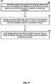
- FIG. 4 shows an optical detection method 400, according to examples of the present disclosure.
- the method 400 is a continuation of the method 300.
- the method 400 begins by selecting, at 402, a second test sensor 130 from among the plurality of test sensors 126. An optical beam received from the second test sensor 130 for a comparison with the reflected or scattered optical beam received from the target 152.
- the second test sensor 130 comprises the second test chemical 131.
- the method 400 continues by comparing, 404, a second spectrum obtained from the optical beam received from the second test chemical 131 with the spectrum obtained from the reflected or scattered optical beam that was received from the target 152 using the linear detector array 144, 146.
- the method 400 continues by using the hardware processor to determine, at 406, whether the specific absorption features of the chemical present at the target 152 that appear in the spectrum obtained from the target 152 is more similar to features seen in the first spectrum obtained from the first test sensor 128 or seen in the second spectrum obtained from the second test sensor 130.
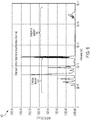
- FIG. 5 shows an example combined spectrum 500 that can be produced by the optical detection method 300, according to examples of the present disclosure.
- the spectrum 500 shows a first portion comprising the chemical spectrum 505 that includes specific absorption features of a test chemical, such as the first test chemical 130 or the second test chemical 131, and which shows the increased signal-to-noise ratio relative to the background.
- the spectrum 500 also shows a second portion comprising the background spectrum 510.
- FIG. 6 shows an example spectrum 600 taken from a target 152 and that has not been combined with a spectrum obtained from a test chemical, such as the first test chemical 130 or the second test chemical 131.
- the spectrum 600 shows a first portion comprising the chemical spectrum 505 and a second portion comprising the background spectrum 610.
Landscapes
- Physics & Mathematics (AREA)
- Chemical & Material Sciences (AREA)
- Health & Medical Sciences (AREA)
- Life Sciences & Earth Sciences (AREA)
- General Physics & Mathematics (AREA)
- General Health & Medical Sciences (AREA)
- Analytical Chemistry (AREA)
- Biochemistry (AREA)
- Immunology (AREA)
- Pathology (AREA)
- Spectroscopy & Molecular Physics (AREA)
- Engineering & Computer Science (AREA)
- Nuclear Medicine, Radiotherapy & Molecular Imaging (AREA)
- Combustion & Propulsion (AREA)
- Food Science & Technology (AREA)
- Medicinal Chemistry (AREA)
- Optics & Photonics (AREA)
- Investigating Or Analysing Materials By Optical Means (AREA)
Abstract
Description
- The present disclosure is directed to systems and methods for chemical detection. More particularly, the present disclosure is directed to remote chemical detection systems and methods using optical absorption detection with a matched reference.
- It is known in the art to detect certain constituents in a chemical cloud in the air by spectral analysis of the molecules making up the cloud. This type of chemical detection has many applications, including detecting natural gas leaks from underground pipes, chemical clouds from chemical spills, volatile organic vapor (VOC) from chemical processes, pollution from smoke stacks and the like, military chemical warfare agents, and other toxic gases present in the air. Typically, this type of spectral analysis of a chemical cloud is performed remotely, sometimes up to 10-20 km away, because the constituents in the cloud may be toxic, and thus a threat to health, or it may not be possible to directly detect the chemical cloud. The distance the detecting instrument has to be from the cloud for this remote type of passive sensing depends on the particular application, and different systems exist for different applications.
- To perform this type of detection and analysis, a spectrometer, such as a Fourier transform infrared (FTIR) spectrometer, is directed towards the chemical agent cloud from a remote location, so that it passively receives emissions therefrom. Typical optical absorption detection systems operate independent of each other and rely on long optical path lengths to absorb enough of a species for detection. The spectral display generated by the spectrometer from the emissions provides emission lines and bands at certain wavelengths that is indicative of the atoms and molecules in the cloud. Because each material has its own spectral "fingerprint" representative of its molecules, the detected spectral display can be compared to a known "fingerprint" of a particular chemical to determine if that chemical exists in the cloud.
- What is needed is an improved remote chemical detection system that addresses various problem of the conventional approaches.
- In accordance with examples of the present disclosure, an optical detection method is provided that comprises directing an optical beam toward a target; selecting a first test sensor from among a plurality of test sensors to compare with radiation received from the target, wherein the first test sensor comprises a first test chemical; receiving a reflected or scattered optical beam from the target; comparing a first spectrum from the first test chemical with a spectrum of the reflected or scattered optical beam that was received using a linear detector array; determining a likely chemical from the target based on the comparing using a hardware processor; and providing an output based on the determining.
- In some examples, the optical detection method further comprises selecting a second test sensor from among a plurality of test sensors to compare with radiation received from the target, wherein the second test sensor comprises a second test chemical; comparing a second spectrum from the second test chemical with the spectrum of the reflected or scattered optical beam that was received using the linear detector array; and determining whether the likely chemical from the target is closer to the first spectrum or the second spectrum using the hardware processor.
- In some examples, each of the plurality of test sensors comprise a nanomaterial that is impregnated with a different test chemical. In some examples, the directing further comprises expanding the optical beam with a beam expander and steering the optical beam with a beam steering mirror, wherein the optical beam at the target comprises a plurality of spatially displaced optical beams. In some examples, the selecting further comprises heating the first test sensor to a temperature sufficient to release the first test chemical from the first test sensor. In some examples, the first test sensor is selected based on an initial assessment of the likely chemical from the target. In some examples, each test sensor of the plurality of test sensors is tested prior to providing the output.
- In accordance with examples of the present disclosure, an optical detection device is provided. The optical detection device comprises a transmitter configured to direct an optical beam toward a target and configured to select a first test sensor from among a plurality of test sensors to compare with radiation received from the target, wherein the first test sensor comprises a first test chemical; a receiver configured to receive a reflected or scattered optical beam from the target; a linear detector array configured to compare a first spectrum from the first test chemical with a spectrum of the reflected or scattered optical beam that was received; a hardware processor configured to determine a likely chemical from the target based on the comparing; and an output interface configured to provide an output based on the determining. In some examples, each of the plurality of test sensors comprise a nanomaterial that is impregnated with a different test chemical. In some examples, each of the plurality of test sensors comprise a capsule with a different test chemical. In some examples, the transmitter further comprises a heat source configured to heat the first test sensor to a temperature sufficient to release the first test chemical from the first test sensor. In some examples, the transmitter further comprises a beam expander configured to expand the optical beam and a beam steering mirror configured to steer the optical beam, wherein the optical beam at the target comprises a plurality of spatially displaced optical beams. In some examples, the optical detection device further comprises an integrated near infrared comb device, an integrated mid-infrared comb device, or both, where an output of the integrated near infrared comb device and the integrated mid-infrared comb device is provided to the transmitter. In some examples, the receiver further comprises a beam focusing device configured to receive the reflected or scattered optical beam from the target and one or more scan mirrors configured to provide one or more scanned optical beam to the linear detector array. In some examples, the first test sensor is selected based on an initial assessment of the likely chemical from the target. In some examples, each test sensor of the plurality of test sensors is tested prior to providing the output.
- It is to be understood that both the foregoing general description and the following detailed description are exemplary and explanatory only and are not restrictive of the present teachings, as claimed.
-
Clause 1. An optical detection method comprising: directing (302) an optical beam toward a target (152); selecting (306) a first test sensor (128) from among a plurality of test sensors to compare with radiation received from the target (152), wherein the first test sensor (128) comprises a first test chemical (129); receiving (310) a reflected or scattered optical beam from the target (152); comparing (312) a first spectrum from the first test chemical (129) with a spectrum of the reflected or scattered optical beam that was received using a linear detector array (144, 146); determining (314) a likely chemical from the target (152) based on the comparing using a hardware processor; and providing (316) an output based on the determining. - Clause 2. The optical detection method of
clause 1, further comprising: selecting (402) a second test sensor (130) from among a plurality of test sensors to compare with radiation received from the target (152), wherein the second test sensor (130) comprises a second test chemical (131); comparing (404) a second spectrum from the second test chemical (131) with the spectrum of the reflected or scattered optical beam that was received using the linear detector array (144, 146); and determining (406) whether the likely chemical from the target is closer to the first spectrum or the second spectrum using the hardware processor. - Clause 3. The optical detection method of
clause 1 or 2, wherein each of the plurality of test sensors comprise a nanomaterial that is impregnated with a different test chemical. - Clause 4. The optical detection method of any of clauses 1-3, wherein the directing (302) further comprises expanding (304) the optical beam with a beam expander (120) and steering the optical beam with a beam steering mirror (122), wherein the optical beam at the target (152) comprises a plurality of spatially displaced optical beams.
- Clause 5. The optical detection method of any of clauses 1-4, wherein the selecting (306) further comprises heating (308) the first test sensor (128) to a temperature sufficient to release the first test chemical (129) from the first test sensor (128).
- Clause 6. The optical detection method of any of clauses 1-5, wherein the first test sensor (128) is selected based on an initial assessment of the likely chemical from the target (152).
- Clause 7. The optical detection method of any of clauses 1-6, wherein each test sensor of the plurality of test sensors is tested prior to providing the output.
- Clause 8. An optical detection device comprising: a transmitter (118) configured to direct an optical beam toward a target (152) and configured to select a first test sensor (128) from among a plurality of test sensors to compare with radiation received from the target (152), wherein the first test sensor (128) comprises a first test chemical (129); a receiver (142) configured to receive a reflected or scattered optical beam from the target (152); a linear detector array (144, 146) configured to compare a first spectrum from the first test chemical (129) with a spectrum of the reflected or scattered optical beam that was received; a hardware processor (150) configured to determine a likely chemical from the target (152) based on the comparing; and an output interface configured to provide an output based on the determining.
- Clause 9. The optical detection device of clause 8, wherein each of the plurality of test sensors comprise a nanomaterial that is impregnated with a different test chemical.
-
Clause 10. The optical detection device of clause 8 or 9, wherein each of the plurality of test sensors comprise a capsule with a different test chemical. - Clause 11. The optical detection device of any of clauses 8-10, wherein the transmitter (118) further comprises a heat source (140) configured to heat the first test sensor (128) to a temperature sufficient to release the first test chemical (129) from the first test sensor (128).
- Clause 12. The optical detection device of any of clauses 8-11, wherein the transmitter (118) further comprises a beam expander (120) configured to expand the optical beam and a beam steering mirror (122) configured to steer the optical beam, wherein the optical beam at the target (152) comprises a plurality of spatially displaced optical beams (154).
-
Clause 13. The optical detection device of any of clauses 8-12, further comprising an integrated near infrared comb device (104), an integrated mid-infrared comb device (106), or both, where an output of the integrated near infrared comb device (104) and the integrated mid-infrared comb device (106) is provided to the transmitter (118). -
Clause 14. The optical detection device of any of clauses 8-13, wherein the receiver (142) further comprises a beam focusing device (138) configured to receive the reflected or scattered optical beam from the target (152) and one or more scan mirrors (142) configured to provide one or more scanned optical beam to the linear detector array (144, 146). - Clause 15. The optical detection device of any of clauses 8-14, wherein the first test sensor (128) is selected based on an initial assessment of the likely chemical from the target (152).
- Clause 16. An optical detection device comprising: a transmitter (118) configured to direct an optical beam toward a target (152) and configured to select a first test sensor (128) from among a plurality of test sensors to compare with radiation received from the target (152), wherein the first test sensor (128) comprises a first test chemical (129); a receiver (142) configured to receive a reflected or scattered optical beam from the target (152); a linear detector array (144, 146) configured to compare a first spectrum from the first test chemical (129) with a spectrum of the reflected or scattered optical beam that was received; a hardware processor (150) configured to determine a likely chemical from the target (152) based on the comparing; and an output interface configured to provide an output based on the determining.
- Clause 17. The optical detection device of clause 16, wherein each of the plurality of test sensors comprise a nanomaterial that is impregnated with a different test chemical.
- Clause 18. The optical detection device of clauses 16-17, wherein each of the plurality of test sensors comprise a capsule with a different test chemical.
- Clause 19. The optical detection device of clauses 16-18, wherein the transmitter (118) further comprises a heat source (140) configured to heat the first test sensor (128) to a temperature sufficient to release the first test chemical (129) from the first test sensor (128).
- Clause 20. The optical detection device of clauses 16-19, wherein the transmitter (118) further comprises a beam expander (120) configured to expand the optical beam and a beam steering mirror (122) configured to steer the optical beam, wherein the optical beam at the target (152) comprises a plurality of spatially displaced optical beams (154).
- Clause 21. The optical detection device of clauses 16-20, further comprising an integrated near infrared comb device (104), an integrated mid-infrared comb device (106), or both, where an output of the integrated near infrared comb device (104) and the integrated mid-infrared comb device (106) is provided to the transmitter (118).
- Clause 22. The optical detection device of clauses 16-21, wherein the receiver (142) further comprises a beam focusing device (138) configured to receive the reflected or scattered optical beam from the target (152) and one or more scan mirrors (143) configured to provide one or more scanned optical beam to the linear detector array (144, 146).
- Clause 23. The optical detection device of clauses 16-22, wherein the first test sensor (128) is selected based on an initial assessment of the likely chemical from the target (152).
- Clause 24. The optical detection device of clauses 16-23, wherein each test sensor of the plurality of test sensors is tested prior to providing the output.
- The accompanying drawings, which are incorporated in and constitute a part of this specification, illustrate features of the present teachings and together with the description, serve to explain the principles of the present teachings.
-
FIG. 1 illustrates a block diagram of an optical detection system for chemical detection using a matched reference, according to an implementation. -
FIG. 2 illustrates a schematic view of the block diagram ofFIG. 1 . -
FIG. 3 shows anoptical detection method 300, according to an implementation. -
FIG. 4 shows anoptical detection method 400, according to an implementation. -
FIG. 5 shows anexample spectrum 500 that can be produced byoptical detection method 300, according to examples of the present disclosure. -
FIG. 6 shows anexample spectrum 600 that does not include a reference chemical. - It should be noted that some details of the figures have been simplified and are drawn to facilitate understanding rather than to maintain strict structural accuracy, detail, and scale.
- Reference will now be made in detail to the present teachings, examples of which are illustrated in the accompanying drawings. In the drawings, like reference numerals have been used throughout to designate identical elements. In the following description, reference is made to the accompanying drawings that form a part thereof, and in which is shown by way of illustration specific examples of practicing the present teachings. The following description is, therefore, merely exemplary.
- Generally speaking, features of the present disclosure provides for an optical detection system and method that uses a matched filter (a matched absorption filter) to improve the signal to noise ratio of an optical spectrum. This provides the ability to "pull' a chemical at a target location out of the background and compare a spectrum of the chemical with spectra from one or more test chemicals. The matched filter technique is used to enhance the optical detection of a low concentration compound mixed with a background via absorption by optically combining a matched spectrum without background. The matched spectrum is determined by a detection system and also serves as the source for releasing the test chemical that provides the matched spectrum. The optical detection system and method provides for (1) the use of chemical absorption features in a matched spectrum optically combined with a signature in the background, (2) the use of an orthogonal sensor to determine the chemical release, and (3) the use of the same orthogonal sensor type to generate the release of a test chemical for optical absorption detection. The optical detection system and method provides for an enhancement to matching gaseous outputs of chemicals, including but are not limited to TNT.
- The optical detection system and method can use nanotube chemical sensors that can be heated to release a chemical bonded to the nanotubes so that an optical beam probes the released chemical. The optical detection system and method probes the environment and uses subtractive detection to determine a likely chemical in the environment. The nanotubes can include a functionalized surface with chemical bonds such that, when heated, the chemical is released. The optical beam is directed through the released gas and is analyzed to determine if the environment also has the chemical. The optical detection system and method can use optical spectroscopy of the chemical through either absorption or emission spectroscopy. The optical detection system and method can be used for any type of environmental monitoring, explosives detection, environmental issues at smokestacks, pollution monitors, or fire detection.
-
FIG. 1 illustrates a block diagram of anoptical detection system 100 for chemical detection using a matched reference, according to an implementation. Theoptical detection system 100 comprises elements of an optical system, control system, and network 102 that are configured to produce and control an optical beam. The optical system of theoptical detection system 100 can include an integrated near infrared ("NIR") frequencycomb laser system 104 or an integrated mid infrared ("MIR") frequency comb laser system 106 (or both an integrated near infrared ("NIR") frequencycomb laser system 104 and an integrated mid infrared ("MIR") frequencycomb laser system 106, or more than one integrated near infrared ("NIR") frequencycomb laser system 104 and/or more than one grated mid infrared ("MIR") frequencycomb laser system 106. A frequencycomb laser system comb laser system - The optical system, control system, and network 102 includes a
controller 110 that is configured to control the operation of the integrated NIR frequencycomb laser system 104 and the integrated MIR frequencycomb laser system 106. The optical system, control system, and network 102 also includes anetwork interface 114 and anantenna 116. A global positioning system ("GPS")module 108 can be in communication with thecontroller 110 and themaster controller 112. The optical system, control system, and network 102 also comprises an output interface that is configured to provide an output for a user and/or to be provided to a computer system over a network by thenetwork interface 114 and theantenna 116. - The
optical detection system 100 also comprises atransmitter 118. Thetransmitter 118 is configured to direct an optical beam from the NIR frequencycomb laser system 104 and/or the MIR frequencycomb laser system 106 towards atarget 152. Thetransmitter 118 can comprise abeam expander 120 that is configured to expand the optical beam, and thetransmitter 118 can comprise abeam steering mirror 122 that is configured to steer the optical beam. The optical beam steered towards and received by thetarget 152 can comprise a plurality of spatially displaced optical beams. - The
optical detection system 100 also comprises apoint detection unit 124 that is configured to select a test sensor from among a plurality oftest sensors 126. An optical beam received from the test sensor is compared with an optical beam received from thetarget 152. The plurality oftest sensors 126 includes afirst test sensor 128, asecond test sensor 130, ..., annth test sensor 132. Thefirst test sensor 128 comprises afirst test chemical 129, thesecond test sensor 130 comprises a second test chemical 131, and thenth test sensor 132 comprises annth test chemical 133. Each of the plurality oftest sensors 126 comprises a nanomaterial that is impregnated with a different one of the test chemicals. Each of the plurality oftest sensors 126 can comprise a capsule with a different one of the test chemicals. Thepoint detection unit 124 can also include a heat source 134 configured to heat one or more of the plurality oftest sensors 126 to a temperature sufficient to release the respective test chemicals from the one or more of the plurality oftest sensors 126. In some examples, a single walled carbon nanotube material is used to mimic a natural receptor for molecular recognition, such as for recognition and hence detection of hydrogen sulfide, sulfur mustard or any number of other chemical agents with sensitivity levels of 10 ppm or less. - A
receiver 142 is configured to receive a portion of the optical beams that are reflected or scattered from thetarget 152. Thereceiver 142 comprises acamera 139 and a beam focusing device, namely abeam condenser 138, that is configured to operate in reverse to thebeam expander 120 by focusing the plurality of scattered and/or reflected optical beams received from thetarget 152. Thereceiver 142 also comprises a NIRlinear detector array 144 and/or a MIRlinear detector array 146, whose outputs are received by thereceiver electronics 148 and processed by a hardware processor, such as by a central processing unit ("CPU") or a graphics processor unit ("GPU") 150. The NIRlinear detector array 144 and/or MIR thelinear detector array 146 are configured to compare one or more spectra taken from an optical beam received from one or more of the test chemicals. For example, a first spectrum obtained from the optical beam received from thefirst test chemical 130 may be compared with a spectrum obtained from the reflected or scattered optical beam that was received from thetarget 152. The processor, such as theGPU 150, is configured to determine a chemical present in thetarget 152 based on the results of the comparison of the spectra. -
FIG. 2 illustrates aschematic view 200 of theoptical detection system 100, showing additional details. The integrated NIR frequencycomb laser system 104 and the integrated MIR frequencycomb laser system 106 are configured to produce a first plurality of spatially displacedoptical beams 154 and a second plurality of spatially displacedoptical beams 156, respectively. A portion of the first plurality of spatially displacedoptical beams 154 and the second plurality of spatially displacedoptical beams 156 is directed to thepoint detection unit 124 by afirst mirror 158. The optical beams from thepoint detection unit 124 is directed to thereceiver 142 by asecond mirror 160, which is combined with radiation received from thetarget 152 by a beam splitter 162 and/or a grating or aprism 139 to be analyzed by the NIRlinear detector array 144 and/or the MIRlinear detector array 146, thereceiver electronics 148, and theGPU 150. -
FIG. 3 shows anoptical detection method 300, according to examples of the present disclosure. Theoptical detection method 300 can begin by directing, at 302, the optical beam toward thetarget 152. In some examples, directing the optical beam further comprises expanding, at 304, the optical beam with thebeam expander 120 and steering the optical beam with thebeam steering mirror 122. The optical beam steered towards thetarget 152 comprises a plurality of spatially displaced optical beams. - The
optical detection method 300 can continue by selecting, at 306, thefirst test sensor 128 from among the plurality oftest sensors 126. An optical beam received from thefirst test sensor 128 is compared with the portion of the optical beam radiation reflected or scattered from thetarget 152. In some examples, selecting thefirst test sensor 128 can further comprise heating, at 308, thefirst test sensor 128 to a temperature sufficient to release thefirst test chemical 130 from thefirst test sensor 128. Thefirst test sensor 128 can comprise thefirst test chemical 130, thesecond sensor 132 can comprise the second test chemical 131, ..., the nth test sensor 136 can comprise thenth test chemical 133. Each of the plurality oftest sensors 126 can comprise a nanomaterial that is impregnated with a different test chemical. - The
optical detection method 300 can continue by receiving, at 310, the reflected or scattered optical beam from thetarget 152. - The
optical detection method 300 can continue by comparing, at 312, the first spectrum obtained from thefirst test chemical 130 with the spectrum obtained from the reflected or scattered optical beam that was received by thelinear detector array - For example, the local atmosphere of one of the plurality of
test sensors 126 can be interrogated by thetransmitter 118. The test sensor, such as thefirst test sensor 128, is heated and thefirst test chemical 130 is released into the local atmosphere ingested by the test sensor. The releasedfirst test chemical 130 and local atmosphere can then be interrogated by the portion of the optical beam separated by thefirst mirror 158 from thetransmitter 118 as it passes through thepoint detection unit 124. - The
optical detection method 300 can continue by using a hardware processor to determine (identify), at 314, a chemical present at thetarget 152 based on comparing the spectra at 312. - The
optical detection method 300 can continue by providing, at 316, an output based on the determining. - Typically a chemical spectrum (a spectrum collected from a chemical sample) is defined by its absorption features as a function of frequency. A chemical spectrum will have specific absorption features at different frequencies associated with the constituent chemicals that make up the chemical sample. The specific absorption features at different frequencies is a signature of each constituent chemical. By identifying the specific absorption features, a database may be generated in a controlled environment with the
optical detection system 100. However, the specific features of a chemical may be masked or hidden amongst the background signal in a spectrum. A method of increasing the specific absorption features of the chemical is provided by the present disclosure as will now be described. - As described above, the optical beams received from the
target 152 and the selected one of the plurality oftest sensors 126 are combined. This means that the spectrum from thetarget 152 is effectively added to the spectrum from the selected one of the plurality oftest sensors 126 to form a combined spectrum. As the spectrum from the selected one of the plurality oftest sensors 126 acts as a matched filter, this addition of the spectra causes the specific absorption features in the combined spectrum to increase relative to the background, i.e. there is an improvement in the signal to background ratio. A processing method can then be used to correlate the combined spectrum to spectra stored in a database such that an identification of a chemical in thetarget 152 may be made with the highest confidence. -
FIG. 4 shows anoptical detection method 400, according to examples of the present disclosure. Themethod 400 is a continuation of themethod 300. Themethod 400 begins by selecting, at 402, asecond test sensor 130 from among the plurality oftest sensors 126. An optical beam received from thesecond test sensor 130 for a comparison with the reflected or scattered optical beam received from thetarget 152. Thesecond test sensor 130 comprises the second test chemical 131. - The
method 400 continues by comparing, 404, a second spectrum obtained from the optical beam received from the second test chemical 131 with the spectrum obtained from the reflected or scattered optical beam that was received from thetarget 152 using thelinear detector array - The
method 400 continues by using the hardware processor to determine, at 406, whether the specific absorption features of the chemical present at thetarget 152 that appear in the spectrum obtained from thetarget 152 is more similar to features seen in the first spectrum obtained from thefirst test sensor 128 or seen in the second spectrum obtained from thesecond test sensor 130. -
FIG. 5 shows an example combinedspectrum 500 that can be produced by theoptical detection method 300, according to examples of the present disclosure. Thespectrum 500 shows a first portion comprising thechemical spectrum 505 that includes specific absorption features of a test chemical, such as thefirst test chemical 130 or the second test chemical 131, and which shows the increased signal-to-noise ratio relative to the background. Thespectrum 500 also shows a second portion comprising thebackground spectrum 510. - By comparison,
FIG. 6 shows anexample spectrum 600 taken from atarget 152 and that has not been combined with a spectrum obtained from a test chemical, such as thefirst test chemical 130 or the second test chemical 131. Thespectrum 600 shows a first portion comprising thechemical spectrum 505 and a second portion comprising thebackground spectrum 610. - Notwithstanding that the numerical ranges and parameters setting forth the broad scope of the disclosure are approximations, the numerical values set forth in the specific examples are reported as precisely as possible. Any numerical value, however, inherently contains certain errors necessarily resulting from the standard deviation found in their respective testing measurements. Moreover, all ranges disclosed herein are to be understood to encompass any and all sub-ranges subsumed therein.
- While the present teachings have been illustrated with respect to one or more implementations, alterations and/or modifications can be made to the illustrated examples without departing from the spirit and scope of the appended claims. In addition, while a particular feature of the present teachings may have been disclosed with respect to only one of several implementations, such feature may be combined with one or more other features of the other implementations as may be desired and advantageous for any given or particular function. As used herein, the term "at least one of A and B" with respect to a listing of items such as, for example, A and B, means A alone, B alone, or A and B. Those skilled in the art will recognize that these and other variations are possible. Furthermore, to the extent that the terms "including," "includes," "having," "has," "with," or variants thereof are used in either the detailed description and the claims, such terms are intended to be inclusive in a manner similar to the term "comprising." Further, in the discussion and claims herein, the term "about" indicates that the value listed may be somewhat altered, as long as the alteration does not result in nonconformance of the process or structure to the intended purpose described herein. Finally, "exemplary" indicates the description is used as an example, rather than implying that it is an ideal.
- It will be appreciated that variants of the above-disclosed and other features and functions, or alternatives thereof, may be combined into many other different systems or applications. Various presently unforeseen or unanticipated alternatives, modifications, variations, or improvements therein may be subsequently made by those skilled in the art which are also intended to be encompasses by the following claims.
Claims (15)
- An optical detection method comprising:directing (302) an optical beam toward a target (152);receiving (310), at a linear detector array (144, 146), the optical beam after it has been reflected or scattered from the target (152) to form a reflected or scattered optical beam;obtaining a target spectrum from the reflected or scattered optical beam received from the target (152) by the linear detector array (144, 146);selecting (306) a first test sensor (128) from among a plurality of test sensors, wherein the first test sensor (128) comprises a first test chemical (130);obtaining a first matched spectrum from the first test chemical (130);performing (312) a first matched filter comparison of the target spectrum with the first matched spectrum, the first matched spectrum corresponding to a first matched filter;determining (314) a first candidate chemical likely to be present in the target (152) based on the first matched filter comparison; andproviding (316) an identification of the first candidate chemical as an output.
- The optical detection method of claim 1, wherein obtaining the first matched spectrum from the first test chemical (130) comprises:directing (302) a further optical beam toward the first test sensor (128);receiving (310), at the linear detector array (144, 146), the further optical beam after it has been reflected or scattered from the first test sensor (128) to form a further reflected or scattered optical beam; andobtaining the first matched spectrum from the further reflected or scattered optical beam received by the linear detector array (144, 146).
- The optical detection method of claim 2, further comprising heating (308) the first test sensor (128) to a temperature sufficient to release the first test chemical (130) from the first test sensor (128) prior to directing (302) the further optical beam toward the first test sensor (128).
- The optical detection method of any of claims 1-3, wherein the first test sensor (128) is selected based on user input provided by a user after an initial assessment of the first candidate chemical likely to be present in the target (152).
- The optical detection method of any of claims 1-4, further comprising:selecting (402) a second test sensor (130) from among the plurality of test sensors, wherein the second test sensor (130) comprises a second test chemical (131);obtaining a second matched spectrum from the second test chemical (131);performing (404) a second matched filter comparison of the target spectrum with the second matched spectrum, the second matched spectrum corresponding to a second matched filter;determining (314) a second candidate chemical likely to be present in the target (152) based on the second matched filter comparison; anddetermining (406) whether the first candidate chemical identified using the first matched spectrum or the second candidate chemical identified using the second matched spectrum is more likely to be present in the target.
- The optical detection method of any of claims 1-5, wherein obtaining the second matched spectrum from the second test chemical (131) comprises:directing (302) a still further optical beam toward the second test sensor (130);receiving (310), at the linear detector array (144, 146), the still further optical beam after it has been reflected or scattered from the second test sensor (130) to form a still further reflected or scattered optical beam; andobtaining the second matched spectrum from the still further reflected or scattered optical beam received by the linear detector array (144, 146).
- The optical detection method of any of claims 1-6, further comprising expanding (304) the optical beam with a beam expander (120) to form an expanded optical beam, and steering the expanded optical beam towards the target (152) with a beam steering mirror (122), such that the expanded optical beam comprises a plurality of spatially displaced optical beams at the target (152).
- The optical detection method of any of claims 1-7, wherein each of the plurality of test sensors comprise a nanomaterial that is impregnated with a different test chemical.
- The optical detection method of any of claims 1-8, comprising:selecting (402) all test sensors from among the plurality of test sensors, wherein each test sensor (132) comprises a different test chemical;obtaining a matched spectrum from each of the test chemicals;performing (404) further matched filter comparisons of the target spectrum with each matched spectrum obtained from each test chemical, each matched spectrum corresponding to a matched filter; anddetermining (314) a candidate chemical likely to be present in the target (152) for each of the further matched filter comparisons; anddetermining (406) the candidate chemical most likely to be present in the target (152) from the determined candidate chemicals prior to providing the output.
- An optical detection device comprising:a transmitter (118) configured to direct an optical beam toward a target (152);a linear detector array (144, 146) configured:to receive the optical beam after it has been reflected or scattered from the target (152) to form a reflected or scattered optical beam; andto obtain a target spectrum from the reflected or scattered optical beam received from the target (152) by the linear detector array (144, 146);wherein:the optical detection device is configured:to select a test sensor (128) from among a plurality of test sensors, wherein the test sensor (128) comprises a test chemical (130), andto obtain a matched spectrum from the test chemical (130);the linear detector array (144, 146) is configured to perform a matched filter comparison of the target spectrum with the matched spectrum, the matched spectrum corresponding to a matched filter; andthe optical detection device further comprises:
a hardware processor (150) configured to determine a candidate chemical likely to be present in the target (152) based on the matched filter comparison; andan output interface configured to provide an identification of the candidate chemical as an output. - The optical detection device of claim 10, wherein each of the plurality of test sensors comprise: a nanomaterial that is impregnated with a different test chemical; or a capsule with a different test chemical.
- The optical detection device of claim 10 or 11, further comprising a heat source (140) configured to heat the test sensor (128) to a temperature sufficient to release the test chemical (130) from the test sensor (128).
- The optical detection device of any of claims 10-12, further comprising a beam expander (120) configured to expand the optical beam to form an expanded optical beam and a beam steering mirror (122) configured to steer the expanded optical beam, such that the optical beam comprises a plurality of spatially displaced optical beams (154) at the target (152).
- The optical detection device of any of claims 10-13, further comprising an integrated near infrared comb device (104) and/or an integrated mid-infrared comb device (106), where an optical output of the integrated near infrared comb device (104) and the integrated mid-infrared comb device (106) is provided to the transmitter (118).
- The optical detection device of any of claims 10-14, wherein the linear detector array (144, 146) further comprises a beam focusing device (138) configured to receive the reflected or scattered optical beam from the target (152), and one or more scan mirrors (142) configured to provide one or more scanned optical beams to the linear detector array (144, 146).
Applications Claiming Priority (1)
| Application Number | Priority Date | Filing Date | Title |
|---|---|---|---|
| US16/220,485 US10809186B2 (en) | 2018-12-14 | 2018-12-14 | Optical detection system and method |
Publications (2)
| Publication Number | Publication Date |
|---|---|
| EP3667296A1 true EP3667296A1 (en) | 2020-06-17 |
| EP3667296B1 EP3667296B1 (en) | 2023-02-01 |
Family
ID=68917406
Family Applications (1)
| Application Number | Title | Priority Date | Filing Date |
|---|---|---|---|
| EP19216248.5A Active EP3667296B1 (en) | 2018-12-14 | 2019-12-13 | Optical detection system and method |
Country Status (5)
| Country | Link |
|---|---|
| US (1) | US10809186B2 (en) |
| EP (1) | EP3667296B1 (en) |
| JP (1) | JP7365864B2 (en) |
| KR (1) | KR102831889B1 (en) |
| CN (1) | CN111323386B (en) |
Families Citing this family (1)
| Publication number | Priority date | Publication date | Assignee | Title |
|---|---|---|---|---|
| CN114414592B (en) * | 2022-01-19 | 2024-04-12 | 中国科学院上海光学精密机械研究所 | Glass bubble detection device and method based on nonlinear holographic thermal image |
Citations (4)
| Publication number | Priority date | Publication date | Assignee | Title |
|---|---|---|---|---|
| US6985818B1 (en) * | 2003-02-06 | 2006-01-10 | The United States Of America As Represented By The Secretary Of The Army | Air sampling method and sensor system for spectroscopic detection and identification of chemical and biological contaminants |
| EP2219022A1 (en) * | 2007-11-07 | 2010-08-18 | Toyota Jidosha Kabushiki Kaisha | Hydrocarbon concentration measuring apparatus and hydrocarbon concentration measuring method |
| US20130265568A1 (en) * | 2012-03-27 | 2013-10-10 | Innovative Science Tools, Inc. | Optical analyzer for identification of materials using transmission spectroscopy |
| WO2018213212A1 (en) * | 2017-05-15 | 2018-11-22 | Leidos, Inc. | Standoff trace chemical detection with active infrared spectroscopy |
Family Cites Families (25)
| Publication number | Priority date | Publication date | Assignee | Title |
|---|---|---|---|---|
| JPS52165681U (en) * | 1976-06-09 | 1977-12-15 | ||
| JPH0830680B2 (en) * | 1990-10-15 | 1996-03-27 | アンリツ株式会社 | Gas detector |
| JP3252682B2 (en) * | 1995-11-13 | 2002-02-04 | 株式会社豊田中央研究所 | High-speed resin identification method and system by infrared spectroscopy |
| US6853452B1 (en) * | 1999-03-17 | 2005-02-08 | University Of Virginia Patent Foundation | Passive remote sensor of chemicals |
| US6353476B1 (en) * | 1999-06-07 | 2002-03-05 | New Chromex, Inc. | Apparatus and method for substantially simultaneous measurement of emissions |
| US7242469B2 (en) * | 2003-05-27 | 2007-07-10 | Opto Trace Technologies, Inc. | Applications of Raman scattering probes |
| US20040259234A1 (en) * | 2003-06-06 | 2004-12-23 | Northrop Grumman Corporation | Detection and analysis of chemical and biological materials |
| US7023545B2 (en) * | 2003-06-12 | 2006-04-04 | Textron Systems Corporation | Chemical identification by flash spectroscopy |
| US6900890B1 (en) * | 2003-11-17 | 2005-05-31 | The Boeing Company | Fiber Raman sensor for remote chemical detection |
| US7283245B2 (en) * | 2004-01-20 | 2007-10-16 | General Electric Company | Handheld device with a disposable element for chemical analysis of multiple analytes |
| JP4211673B2 (en) * | 2004-05-11 | 2009-01-21 | 株式会社Ihi | Substance comparison device and substance comparison method |
| US20090002699A1 (en) * | 2007-06-28 | 2009-01-01 | William Scott Sutherland | Method and device for identifying an unknown substance |
| US10203310B2 (en) * | 2009-01-26 | 2019-02-12 | Detectachem Llc | Chemical detection of substances by utilizing a sample medium impregnated with solid test chemicals |
| US8218146B2 (en) * | 2009-02-13 | 2012-07-10 | Northrop Grumman Systems Corporation | System and method for detecting a target substance |
| US8358420B1 (en) * | 2010-02-26 | 2013-01-22 | System Planning Corporation | Spectrometer for identifying analyte materials |
| JP5783495B2 (en) * | 2011-07-26 | 2015-09-24 | 日立化成株式会社 | Control member for light water reactor |
| US10466236B2 (en) * | 2013-03-29 | 2019-11-05 | Nima Labs, Inc. | System and method for detecting target substances |
| WO2014205007A1 (en) * | 2013-06-17 | 2014-12-24 | Invenio Imaging Inc. | Methods and systems for coherent raman scattering |
| JPWO2015045266A1 (en) * | 2013-09-24 | 2017-03-09 | 国立大学法人東京農工大学 | measuring device |
| US10088414B2 (en) * | 2014-05-07 | 2018-10-02 | Cornell University | On-chip integrated gas sensor based on photonic sensing |
| EP3152566B1 (en) * | 2014-06-03 | 2020-09-09 | The Regents of The University of California | Nanoparticle analyzer |
| WO2016145127A1 (en) * | 2015-03-09 | 2016-09-15 | California Institute Of Technology | Mid-infrared hyperspectral spectroscopy systems and methods thereof |
| JP2016170056A (en) * | 2015-03-13 | 2016-09-23 | コニカミノルタ株式会社 | Gas detector |
| US9857295B2 (en) * | 2015-08-10 | 2018-01-02 | The University Of North Carolina At Charlotte | Comparative discrimination spectral detection system and method for the identification of chemicals with overlapping spectral signatures |
| JP2018087748A (en) * | 2016-11-29 | 2018-06-07 | リコーインダストリアルソリューションズ株式会社 | Gas detection optical device and gas detection device |
-
2018
- 2018-12-14 US US16/220,485 patent/US10809186B2/en active Active
-
2019
- 2019-11-12 JP JP2019204916A patent/JP7365864B2/en active Active
- 2019-12-03 KR KR1020190158952A patent/KR102831889B1/en active Active
- 2019-12-13 CN CN201911283968.9A patent/CN111323386B/en active Active
- 2019-12-13 EP EP19216248.5A patent/EP3667296B1/en active Active
Patent Citations (4)
| Publication number | Priority date | Publication date | Assignee | Title |
|---|---|---|---|---|
| US6985818B1 (en) * | 2003-02-06 | 2006-01-10 | The United States Of America As Represented By The Secretary Of The Army | Air sampling method and sensor system for spectroscopic detection and identification of chemical and biological contaminants |
| EP2219022A1 (en) * | 2007-11-07 | 2010-08-18 | Toyota Jidosha Kabushiki Kaisha | Hydrocarbon concentration measuring apparatus and hydrocarbon concentration measuring method |
| US20130265568A1 (en) * | 2012-03-27 | 2013-10-10 | Innovative Science Tools, Inc. | Optical analyzer for identification of materials using transmission spectroscopy |
| WO2018213212A1 (en) * | 2017-05-15 | 2018-11-22 | Leidos, Inc. | Standoff trace chemical detection with active infrared spectroscopy |
Also Published As
| Publication number | Publication date |
|---|---|
| CN111323386A (en) | 2020-06-23 |
| US10809186B2 (en) | 2020-10-20 |
| JP2020095022A (en) | 2020-06-18 |
| KR20200074868A (en) | 2020-06-25 |
| EP3667296B1 (en) | 2023-02-01 |
| JP7365864B2 (en) | 2023-10-20 |
| US20200191708A1 (en) | 2020-06-18 |
| KR102831889B1 (en) | 2025-07-08 |
| CN111323386B (en) | 2024-04-19 |
Similar Documents
| Publication | Publication Date | Title |
|---|---|---|
| US6731804B1 (en) | Thermal luminescence liquid monitoring system and method | |
| US8358420B1 (en) | Spectrometer for identifying analyte materials | |
| JP6022456B2 (en) | Method and system for determining the decay constant of a time domain signal | |
| US8345250B1 (en) | System and method for detecting chemical species from a remote sensing platform | |
| Macleod et al. | Broadband standoff detection of large molecules by mid-infrared active coherent laser spectrometry | |
| US20060011840A1 (en) | Coherent differential absorption lidar (dial) | |
| WO2000050867A2 (en) | Programmable active microwave ultrafine resonance spectrometer (pamurs) method and systems | |
| GB2507959A (en) | Characterising hydrocarbon fluids using mid infrared absorption | |
| Phillips et al. | Standoff chemical plume detection in turbulent atmospheric conditions with a swept-wavelength external cavity quantum cascade laser | |
| Witinski et al. | Portable standoff spectrometer for hazard identification using integrated quantum cascade laser arrays from 6.5 to 11 µm. | |
| Tekawade et al. | Towards realization of quantitative atmospheric and industrial gas sensing using THz wave electronics | |
| US8089632B2 (en) | Systems and methods for detecting contaminants | |
| US9335267B2 (en) | Near-IR laser-induced vibrational overtone absorption systems and methods for material detection | |
| US8218146B2 (en) | System and method for detecting a target substance | |
| US7426035B2 (en) | System and method for chemical sensing using trace gas detection | |
| EP3667296A1 (en) | Optical detection system and method | |
| CN113655028A (en) | Volatile organic compound gas remote sensing method, device, equipment and readable storage medium | |
| US7796264B2 (en) | Method and system for enhanced remote detection of low concentration vapors | |
| Kim et al. | Real-time measurement of Ammonia (NH3) in artillery smoke using a passive FT-IR remote sensor | |
| CN218766604U (en) | Open path gas detection system | |
| US10823616B2 (en) | Dual sensor and method for detection of an analyte gas | |
| MacLeod et al. | High sensitivity stand-off detection and quantification of chemical mixtures using an active coherent laser spectrometer (ACLaS) | |
| RU2313779C2 (en) | Correlative-extreme mode of remote monitoring polluted substances | |
| US9116041B1 (en) | System and method for spectral infrared thermal imaging | |
| Moffa et al. | Advancing atmospheric pollution monitoring with airborne THz spectrometer |
Legal Events
| Date | Code | Title | Description |
|---|---|---|---|
| PUAI | Public reference made under article 153(3) epc to a published international application that has entered the european phase |
Free format text: ORIGINAL CODE: 0009012 |
|
| STAA | Information on the status of an ep patent application or granted ep patent |
Free format text: STATUS: THE APPLICATION HAS BEEN PUBLISHED |
|
| AK | Designated contracting states |
Kind code of ref document: A1 Designated state(s): AL AT BE BG CH CY CZ DE DK EE ES FI FR GB GR HR HU IE IS IT LI LT LU LV MC MK MT NL NO PL PT RO RS SE SI SK SM TR |
|
| AX | Request for extension of the european patent |
Extension state: BA ME |
|
| STAA | Information on the status of an ep patent application or granted ep patent |
Free format text: STATUS: REQUEST FOR EXAMINATION WAS MADE |
|
| 17P | Request for examination filed |
Effective date: 20201113 |
|
| RBV | Designated contracting states (corrected) |
Designated state(s): AL AT BE BG CH CY CZ DE DK EE ES FI FR GB GR HR HU IE IS IT LI LT LU LV MC MK MT NL NO PL PT RO RS SE SI SK SM TR |
|
| GRAP | Despatch of communication of intention to grant a patent |
Free format text: ORIGINAL CODE: EPIDOSNIGR1 |
|
| STAA | Information on the status of an ep patent application or granted ep patent |
Free format text: STATUS: GRANT OF PATENT IS INTENDED |
|
| RIC1 | Information provided on ipc code assigned before grant |
Ipc: G01N 21/17 20060101ALN20220228BHEP Ipc: G01N 21/94 20060101ALI20220228BHEP Ipc: G01N 21/3504 20140101AFI20220228BHEP |
|
| INTG | Intention to grant announced |
Effective date: 20220329 |
|
| GRAJ | Information related to disapproval of communication of intention to grant by the applicant or resumption of examination proceedings by the epo deleted |
Free format text: ORIGINAL CODE: EPIDOSDIGR1 |
|
| STAA | Information on the status of an ep patent application or granted ep patent |
Free format text: STATUS: REQUEST FOR EXAMINATION WAS MADE |
|
| INTC | Intention to grant announced (deleted) | ||
| RIC1 | Information provided on ipc code assigned before grant |
Ipc: G01N 21/17 20060101ALN20220711BHEP Ipc: G01N 21/94 20060101ALI20220711BHEP Ipc: G01N 21/3504 20140101AFI20220711BHEP |
|
| GRAP | Despatch of communication of intention to grant a patent |
Free format text: ORIGINAL CODE: EPIDOSNIGR1 |
|
| STAA | Information on the status of an ep patent application or granted ep patent |
Free format text: STATUS: GRANT OF PATENT IS INTENDED |
|
| INTG | Intention to grant announced |
Effective date: 20220822 |
|
| GRAS | Grant fee paid |
Free format text: ORIGINAL CODE: EPIDOSNIGR3 |
|
| GRAA | (expected) grant |
Free format text: ORIGINAL CODE: 0009210 |
|
| STAA | Information on the status of an ep patent application or granted ep patent |
Free format text: STATUS: THE PATENT HAS BEEN GRANTED |
|
| AK | Designated contracting states |
Kind code of ref document: B1 Designated state(s): AL AT BE BG CH CY CZ DE DK EE ES FI FR GB GR HR HU IE IS IT LI LT LU LV MC MK MT NL NO PL PT RO RS SE SI SK SM TR |
|
| REG | Reference to a national code |
Ref country code: GB Ref legal event code: FG4D |
|
| REG | Reference to a national code |
Ref country code: CH Ref legal event code: EP Ref country code: AT Ref legal event code: REF Ref document number: 1547043 Country of ref document: AT Kind code of ref document: T Effective date: 20230215 |
|
| REG | Reference to a national code |
Ref country code: DE Ref legal event code: R096 Ref document number: 602019025004 Country of ref document: DE |
|
| REG | Reference to a national code |
Ref country code: IE Ref legal event code: FG4D |
|
| RAP4 | Party data changed (patent owner data changed or rights of a patent transferred) |
Owner name: THE BOEING COMPANY |
|
| REG | Reference to a national code |
Ref country code: LT Ref legal event code: MG9D |
|
| REG | Reference to a national code |
Ref country code: NL Ref legal event code: MP Effective date: 20230201 |
|
| P01 | Opt-out of the competence of the unified patent court (upc) registered |
Effective date: 20230516 |
|
| REG | Reference to a national code |
Ref country code: AT Ref legal event code: MK05 Ref document number: 1547043 Country of ref document: AT Kind code of ref document: T Effective date: 20230201 |
|
| PG25 | Lapsed in a contracting state [announced via postgrant information from national office to epo] |
Ref country code: RS Free format text: LAPSE BECAUSE OF FAILURE TO SUBMIT A TRANSLATION OF THE DESCRIPTION OR TO PAY THE FEE WITHIN THE PRESCRIBED TIME-LIMIT Effective date: 20230201 Ref country code: PT Free format text: LAPSE BECAUSE OF FAILURE TO SUBMIT A TRANSLATION OF THE DESCRIPTION OR TO PAY THE FEE WITHIN THE PRESCRIBED TIME-LIMIT Effective date: 20230601 Ref country code: NO Free format text: LAPSE BECAUSE OF FAILURE TO SUBMIT A TRANSLATION OF THE DESCRIPTION OR TO PAY THE FEE WITHIN THE PRESCRIBED TIME-LIMIT Effective date: 20230501 Ref country code: NL Free format text: LAPSE BECAUSE OF FAILURE TO SUBMIT A TRANSLATION OF THE DESCRIPTION OR TO PAY THE FEE WITHIN THE PRESCRIBED TIME-LIMIT Effective date: 20230201 Ref country code: LV Free format text: LAPSE BECAUSE OF FAILURE TO SUBMIT A TRANSLATION OF THE DESCRIPTION OR TO PAY THE FEE WITHIN THE PRESCRIBED TIME-LIMIT Effective date: 20230201 Ref country code: LT Free format text: LAPSE BECAUSE OF FAILURE TO SUBMIT A TRANSLATION OF THE DESCRIPTION OR TO PAY THE FEE WITHIN THE PRESCRIBED TIME-LIMIT Effective date: 20230201 Ref country code: HR Free format text: LAPSE BECAUSE OF FAILURE TO SUBMIT A TRANSLATION OF THE DESCRIPTION OR TO PAY THE FEE WITHIN THE PRESCRIBED TIME-LIMIT Effective date: 20230201 Ref country code: ES Free format text: LAPSE BECAUSE OF FAILURE TO SUBMIT A TRANSLATION OF THE DESCRIPTION OR TO PAY THE FEE WITHIN THE PRESCRIBED TIME-LIMIT Effective date: 20230201 Ref country code: AT Free format text: LAPSE BECAUSE OF FAILURE TO SUBMIT A TRANSLATION OF THE DESCRIPTION OR TO PAY THE FEE WITHIN THE PRESCRIBED TIME-LIMIT Effective date: 20230201 |
|
| PG25 | Lapsed in a contracting state [announced via postgrant information from national office to epo] |
Ref country code: SE Free format text: LAPSE BECAUSE OF FAILURE TO SUBMIT A TRANSLATION OF THE DESCRIPTION OR TO PAY THE FEE WITHIN THE PRESCRIBED TIME-LIMIT Effective date: 20230201 Ref country code: PL Free format text: LAPSE BECAUSE OF FAILURE TO SUBMIT A TRANSLATION OF THE DESCRIPTION OR TO PAY THE FEE WITHIN THE PRESCRIBED TIME-LIMIT Effective date: 20230201 Ref country code: IS Free format text: LAPSE BECAUSE OF FAILURE TO SUBMIT A TRANSLATION OF THE DESCRIPTION OR TO PAY THE FEE WITHIN THE PRESCRIBED TIME-LIMIT Effective date: 20230601 Ref country code: GR Free format text: LAPSE BECAUSE OF FAILURE TO SUBMIT A TRANSLATION OF THE DESCRIPTION OR TO PAY THE FEE WITHIN THE PRESCRIBED TIME-LIMIT Effective date: 20230502 Ref country code: FI Free format text: LAPSE BECAUSE OF FAILURE TO SUBMIT A TRANSLATION OF THE DESCRIPTION OR TO PAY THE FEE WITHIN THE PRESCRIBED TIME-LIMIT Effective date: 20230201 |
|
| PG25 | Lapsed in a contracting state [announced via postgrant information from national office to epo] |
Ref country code: SM Free format text: LAPSE BECAUSE OF FAILURE TO SUBMIT A TRANSLATION OF THE DESCRIPTION OR TO PAY THE FEE WITHIN THE PRESCRIBED TIME-LIMIT Effective date: 20230201 Ref country code: RO Free format text: LAPSE BECAUSE OF FAILURE TO SUBMIT A TRANSLATION OF THE DESCRIPTION OR TO PAY THE FEE WITHIN THE PRESCRIBED TIME-LIMIT Effective date: 20230201 Ref country code: EE Free format text: LAPSE BECAUSE OF FAILURE TO SUBMIT A TRANSLATION OF THE DESCRIPTION OR TO PAY THE FEE WITHIN THE PRESCRIBED TIME-LIMIT Effective date: 20230201 Ref country code: DK Free format text: LAPSE BECAUSE OF FAILURE TO SUBMIT A TRANSLATION OF THE DESCRIPTION OR TO PAY THE FEE WITHIN THE PRESCRIBED TIME-LIMIT Effective date: 20230201 Ref country code: CZ Free format text: LAPSE BECAUSE OF FAILURE TO SUBMIT A TRANSLATION OF THE DESCRIPTION OR TO PAY THE FEE WITHIN THE PRESCRIBED TIME-LIMIT Effective date: 20230201 |
|
| REG | Reference to a national code |
Ref country code: DE Ref legal event code: R097 Ref document number: 602019025004 Country of ref document: DE |
|
| PG25 | Lapsed in a contracting state [announced via postgrant information from national office to epo] |
Ref country code: SK Free format text: LAPSE BECAUSE OF FAILURE TO SUBMIT A TRANSLATION OF THE DESCRIPTION OR TO PAY THE FEE WITHIN THE PRESCRIBED TIME-LIMIT Effective date: 20230201 |
|
| PLBE | No opposition filed within time limit |
Free format text: ORIGINAL CODE: 0009261 |
|
| STAA | Information on the status of an ep patent application or granted ep patent |
Free format text: STATUS: NO OPPOSITION FILED WITHIN TIME LIMIT |
|
| 26N | No opposition filed |
Effective date: 20231103 |
|
| PG25 | Lapsed in a contracting state [announced via postgrant information from national office to epo] |
Ref country code: SI Free format text: LAPSE BECAUSE OF FAILURE TO SUBMIT A TRANSLATION OF THE DESCRIPTION OR TO PAY THE FEE WITHIN THE PRESCRIBED TIME-LIMIT Effective date: 20230201 |
|
| PG25 | Lapsed in a contracting state [announced via postgrant information from national office to epo] |
Ref country code: IT Free format text: LAPSE BECAUSE OF FAILURE TO SUBMIT A TRANSLATION OF THE DESCRIPTION OR TO PAY THE FEE WITHIN THE PRESCRIBED TIME-LIMIT Effective date: 20230201 |
|
| REG | Reference to a national code |
Ref country code: CH Ref legal event code: PL |
|
| PG25 | Lapsed in a contracting state [announced via postgrant information from national office to epo] |
Ref country code: LU Free format text: LAPSE BECAUSE OF NON-PAYMENT OF DUE FEES Effective date: 20231213 |
|
| PG25 | Lapsed in a contracting state [announced via postgrant information from national office to epo] |
Ref country code: MC Free format text: LAPSE BECAUSE OF FAILURE TO SUBMIT A TRANSLATION OF THE DESCRIPTION OR TO PAY THE FEE WITHIN THE PRESCRIBED TIME-LIMIT Effective date: 20230201 |
|
| REG | Reference to a national code |
Ref country code: BE Ref legal event code: MM Effective date: 20231231 |
|
| PG25 | Lapsed in a contracting state [announced via postgrant information from national office to epo] |
Ref country code: MC Free format text: LAPSE BECAUSE OF FAILURE TO SUBMIT A TRANSLATION OF THE DESCRIPTION OR TO PAY THE FEE WITHIN THE PRESCRIBED TIME-LIMIT Effective date: 20230201 Ref country code: LU Free format text: LAPSE BECAUSE OF NON-PAYMENT OF DUE FEES Effective date: 20231213 |
|
| REG | Reference to a national code |
Ref country code: IE Ref legal event code: MM4A |
|
| PG25 | Lapsed in a contracting state [announced via postgrant information from national office to epo] |
Ref country code: IE Free format text: LAPSE BECAUSE OF NON-PAYMENT OF DUE FEES Effective date: 20231213 |
|
| PG25 | Lapsed in a contracting state [announced via postgrant information from national office to epo] |
Ref country code: BE Free format text: LAPSE BECAUSE OF NON-PAYMENT OF DUE FEES Effective date: 20231231 |
|
| PG25 | Lapsed in a contracting state [announced via postgrant information from national office to epo] |
Ref country code: CH Free format text: LAPSE BECAUSE OF NON-PAYMENT OF DUE FEES Effective date: 20231231 |
|
| PG25 | Lapsed in a contracting state [announced via postgrant information from national office to epo] |
Ref country code: IE Free format text: LAPSE BECAUSE OF NON-PAYMENT OF DUE FEES Effective date: 20231213 Ref country code: CH Free format text: LAPSE BECAUSE OF NON-PAYMENT OF DUE FEES Effective date: 20231231 Ref country code: BE Free format text: LAPSE BECAUSE OF NON-PAYMENT OF DUE FEES Effective date: 20231231 |
|
| PG25 | Lapsed in a contracting state [announced via postgrant information from national office to epo] |
Ref country code: BG Free format text: LAPSE BECAUSE OF FAILURE TO SUBMIT A TRANSLATION OF THE DESCRIPTION OR TO PAY THE FEE WITHIN THE PRESCRIBED TIME-LIMIT Effective date: 20230201 |
|
| PG25 | Lapsed in a contracting state [announced via postgrant information from national office to epo] |
Ref country code: BG Free format text: LAPSE BECAUSE OF FAILURE TO SUBMIT A TRANSLATION OF THE DESCRIPTION OR TO PAY THE FEE WITHIN THE PRESCRIBED TIME-LIMIT Effective date: 20230201 |
|
| PG25 | Lapsed in a contracting state [announced via postgrant information from national office to epo] |
Ref country code: CY Free format text: LAPSE BECAUSE OF FAILURE TO SUBMIT A TRANSLATION OF THE DESCRIPTION OR TO PAY THE FEE WITHIN THE PRESCRIBED TIME-LIMIT; INVALID AB INITIO Effective date: 20191213 |
|
| PG25 | Lapsed in a contracting state [announced via postgrant information from national office to epo] |
Ref country code: HU Free format text: LAPSE BECAUSE OF FAILURE TO SUBMIT A TRANSLATION OF THE DESCRIPTION OR TO PAY THE FEE WITHIN THE PRESCRIBED TIME-LIMIT; INVALID AB INITIO Effective date: 20191213 |
|
| PG25 | Lapsed in a contracting state [announced via postgrant information from national office to epo] |
Ref country code: TR Free format text: LAPSE BECAUSE OF FAILURE TO SUBMIT A TRANSLATION OF THE DESCRIPTION OR TO PAY THE FEE WITHIN THE PRESCRIBED TIME-LIMIT Effective date: 20230201 |
|
| PGFP | Annual fee paid to national office [announced via postgrant information from national office to epo] |
Ref country code: GB Payment date: 20251229 Year of fee payment: 7 |
|
| PGFP | Annual fee paid to national office [announced via postgrant information from national office to epo] |
Ref country code: FR Payment date: 20251226 Year of fee payment: 7 |
|
| PGFP | Annual fee paid to national office [announced via postgrant information from national office to epo] |
Ref country code: DE Payment date: 20251229 Year of fee payment: 7 |