EP3667168A1 - Injection system with radial in-flow swirl premix gas fuel injectors - Google Patents
Injection system with radial in-flow swirl premix gas fuel injectors Download PDFInfo
- Publication number
- EP3667168A1 EP3667168A1 EP19216502.5A EP19216502A EP3667168A1 EP 3667168 A1 EP3667168 A1 EP 3667168A1 EP 19216502 A EP19216502 A EP 19216502A EP 3667168 A1 EP3667168 A1 EP 3667168A1
- Authority
- EP
- European Patent Office
- Prior art keywords
- injector
- fuel
- swirler
- radial
- injector ring
- Prior art date
- Legal status (The legal status is an assumption and is not a legal conclusion. Google has not performed a legal analysis and makes no representation as to the accuracy of the status listed.)
- Granted
Links
Images


Classifications
-
- F—MECHANICAL ENGINEERING; LIGHTING; HEATING; WEAPONS; BLASTING
- F23—COMBUSTION APPARATUS; COMBUSTION PROCESSES
- F23C—METHODS OR APPARATUS FOR COMBUSTION USING FLUID FUEL OR SOLID FUEL SUSPENDED IN A CARRIER GAS OR AIR
- F23C7/00—Combustion apparatus characterised by arrangements for air supply
- F23C7/002—Combustion apparatus characterised by arrangements for air supply the air being submitted to a rotary or spinning motion
- F23C7/004—Combustion apparatus characterised by arrangements for air supply the air being submitted to a rotary or spinning motion using vanes
-
- F—MECHANICAL ENGINEERING; LIGHTING; HEATING; WEAPONS; BLASTING
- F23—COMBUSTION APPARATUS; COMBUSTION PROCESSES
- F23D—BURNERS
- F23D14/00—Burners for combustion of a gas, e.g. of a gas stored under pressure as a liquid
- F23D14/02—Premix gas burners, i.e. in which gaseous fuel is mixed with combustion air upstream of the combustion zone
-
- F—MECHANICAL ENGINEERING; LIGHTING; HEATING; WEAPONS; BLASTING
- F23—COMBUSTION APPARATUS; COMBUSTION PROCESSES
- F23D—BURNERS
- F23D14/00—Burners for combustion of a gas, e.g. of a gas stored under pressure as a liquid
- F23D14/46—Details
- F23D14/70—Baffles or like flow-disturbing devices
-
- F—MECHANICAL ENGINEERING; LIGHTING; HEATING; WEAPONS; BLASTING
- F23—COMBUSTION APPARATUS; COMBUSTION PROCESSES
- F23R—GENERATING COMBUSTION PRODUCTS OF HIGH PRESSURE OR HIGH VELOCITY, e.g. GAS-TURBINE COMBUSTION CHAMBERS
- F23R3/00—Continuous combustion chambers using liquid or gaseous fuel
- F23R3/02—Continuous combustion chambers using liquid or gaseous fuel characterised by the air-flow or gas-flow configuration
- F23R3/04—Air inlet arrangements
- F23R3/10—Air inlet arrangements for primary air
- F23R3/12—Air inlet arrangements for primary air inducing a vortex
- F23R3/14—Air inlet arrangements for primary air inducing a vortex by using swirl vanes
-
- F—MECHANICAL ENGINEERING; LIGHTING; HEATING; WEAPONS; BLASTING
- F23—COMBUSTION APPARATUS; COMBUSTION PROCESSES
- F23R—GENERATING COMBUSTION PRODUCTS OF HIGH PRESSURE OR HIGH VELOCITY, e.g. GAS-TURBINE COMBUSTION CHAMBERS
- F23R3/00—Continuous combustion chambers using liquid or gaseous fuel
- F23R3/28—Continuous combustion chambers using liquid or gaseous fuel characterised by the fuel supply
- F23R3/286—Continuous combustion chambers using liquid or gaseous fuel characterised by the fuel supply having fuel-air premixing devices
-
- F—MECHANICAL ENGINEERING; LIGHTING; HEATING; WEAPONS; BLASTING
- F23—COMBUSTION APPARATUS; COMBUSTION PROCESSES
- F23R—GENERATING COMBUSTION PRODUCTS OF HIGH PRESSURE OR HIGH VELOCITY, e.g. GAS-TURBINE COMBUSTION CHAMBERS
- F23R3/00—Continuous combustion chambers using liquid or gaseous fuel
- F23R3/28—Continuous combustion chambers using liquid or gaseous fuel characterised by the fuel supply
- F23R3/34—Feeding into different combustion zones
- F23R3/346—Feeding into different combustion zones for staged combustion
-
- F—MECHANICAL ENGINEERING; LIGHTING; HEATING; WEAPONS; BLASTING
- F23—COMBUSTION APPARATUS; COMBUSTION PROCESSES
- F23C—METHODS OR APPARATUS FOR COMBUSTION USING FLUID FUEL OR SOLID FUEL SUSPENDED IN A CARRIER GAS OR AIR
- F23C2900/00—Special features of, or arrangements for combustion apparatus using fluid fuels or solid fuels suspended in air; Combustion processes therefor
- F23C2900/07001—Air swirling vanes incorporating fuel injectors
-
- F—MECHANICAL ENGINEERING; LIGHTING; HEATING; WEAPONS; BLASTING
- F23—COMBUSTION APPARATUS; COMBUSTION PROCESSES
- F23D—BURNERS
- F23D2900/00—Special features of, or arrangements for burners using fluid fuels or solid fuels suspended in a carrier gas
- F23D2900/14—Special features of gas burners
- F23D2900/14021—Premixing burners with swirling or vortices creating means for fuel or air
Definitions
- the present disclosure relates to multipoint injection, and more particularly to multipoint fuel injection, e.g., for gas turbine engines.
- Industrial gas turbine engines can employ radial inflow fuel/air mixers and usually use axially mounted fuel injectors.
- the actual fuel injection is limited to a relatively low number of injection sights, e.g., less than twenty injection sites.
- An injection system includes a radial swirler defining an axis and including a plurality of radial swirl vanes configured to direct a radially inward flow of compressor discharge air entering swirler inlets between the radial swirl vanes in a swirling direction with a circumferential component around the axis.
- the radial swirler includes an outlet oriented in an axial direction to direct swirling compressor discharge air mixed with fuel in an axial direction.
- An injector ring is included radially outward from the swirler inlets. The fuel injector ring is aligned with the axis and includes a plurality of injection orifices directed towards the swirler inlets for injecting fuel into the radial swirler.
- the injector ring can be a first injector ring and a second injector ring can be included axially adjacent to the first injector ring, the second injector ring being aligned with the axis and including a plurality of injection orifices directed towards the swirler inlets for injecting fuel into the radial swirler, wherein the first and second injector rings are connected to two separate, fluidly isolated fuel circuits for staged fuel injection.
- a third injector ring can be included axially adjacent to the first and second injector rings, the third injector ring being aligned with the axis and including a plurality of injection orifices directed towards the swirler inlets for injecting fuel into the radial swirler, wherein the first, second, and third injector rings are connected to three separate, fluidly isolated fuel circuits for staged fuel injection.
- Each swirl vane can define a curved swirl profile extending from a leading edge of the vane to a trailing edge of the vane, wherein the curved swirl profile at the leading edge is normal to a circumference defined by the leading edges of the swirl vanes.
- a combustor case can enclose the radial swirler and the injector ring.
- a converging diverging outer wall can be included in the outlet of the radial swirler.
- a conical inner wall can be mounted inboard of the swirl vanes.
- a combustor liner can be included in board of the combustor case defining a combustion volume therein. The combustor liner can have an inlet connected to the radial swirler with the outlet of the radial swirler in fluid communication with the combustion volume.
- a fuel conduit can pass through a bulkhead of the combustor case and can connect to the injector ring for fluid connection of the injector ring to a source of fuel.
- Second and third injector rings as described above can be included and an exhaust emission gas sampling sensor can be mounted in an outlet of the combustor liner.
- a controller can be operatively connected to receive exhaust emission gas feedback from the exhaust emission gas sampling sensor.
- a plurality of electronic flow divider valves can be included, with one of the valves connected in each respective one of the fuel circuits. The electronic flow divider valves can be operatively connected to the controller for individual control of flow rates to each of the injector rings based on exhaust emission gas feedback.
- a method of fuel injection includes issuing fuel through a plurality of axially adjacent injector rings into a radial swirler.
- the method includes varying flow rate through each of the injector rings individually to control exhaust gas emissions over varying engine operating conditions.
- the method can include using exhaust emission gas sampling feedback to control the flow rate through each of the injector rings.
- a method of injecting includes directing fuel flow from an injector ring to a direction including a circumferential component.
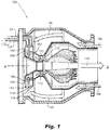
- FIG. 1 a partial view of an exemplary embodiment of an injection system in accordance with the disclosure is shown in Fig. 1 and is designated generally by reference character 100.
- FIGs. 2-4 Other embodiments of injection systems in accordance with the disclosure, or aspects thereof, are provided in Figs. 2-4 , as will be described.
- the systems and methods described herein can be used for fuel injection, e.g., in industrial gas turbine engines.
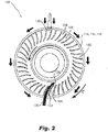
- the injection system 100 includes a radial swirler 102 defining an axis A and including a plurality of radial swirl vanes 104 configured to direct a radially inward flow of compressor discharge air, schematically represented by flow arrows 106, entering swirler inlets 108 (only a few of which are labeled in Fig. 2 for sake of clarity) between the radial swirl vanes 104 in a swirling direction with a circumferential component around the axis A.
- the swirl vanes 104 can be fabricated individually and assembled into the radial swirler 102.
- the circular arrow in Fig. 2 indicates the swirling direction.
- the radial swirler 102 includes an outlet 110 oriented in an axial direction relative to the axis A to direct swirling compressor discharge air mixed with fuel in an axial direction as indicated by the flow arrows 112 in Fig. 1 .
- Three axially adjacent injector rings 114, 116, 118 are included outboard of (radially outward from) the swirler inlets 108 (shown in Fig. 2 ).
- Each fuel injector ring 114, 116, 118 is aligned with the axis A and includes a plurality of injection orifices 120 (only a few of which are identified in Fig. 3 for sake of clarity) directed towards the swirler inlets 108 for injecting fuel into the radial swirler 102.
- the first, second, and third injector rings 114, 116, 118 are connected to three separate, fluidly isolated fuel circuits, i.e. running through the conduits 122, 124, 126, for staged fuel injection. As shown in Figs. 2 and 3 , each conduit 122, 124, 126 terminates at a respective T-junction 128 to supply fuel to the injector rings simultaneously in the counter-clockwise and clockwise directions as indicated by the flow arrows in Fig. 2 .
- each swirl vane 104 defines a curved swirl profile, schematically indicated in Fig. 2 with the arrow 130, extending from a leading edge 132 of the vane 104 to a trailing edge 134 of the vane 104.
- the curved swirl profile arrow 130, leading edge 132, and trailing edge 134 are labeled for only one of the swirl vanes 104 in Fig. 2 for the sake of clarity.
- the curved swirl profile at the leading edge 104 is normal to a circumference C defined by the leading edges 132 of the swirl vanes, and is normal to the circumference of the injection rings 114, 116, 118. As shown in Fig.
- injection orifices 120 there is at least one or two of the injection orifices 120 aligned with each of the swirler inlets 108, and the injection orifices 120 are all positioned to inject fuel between circumferentially adjacent swirl vanes 104 without impinging fuel on the swirl vanes 104.
- a combustor case 136 encloses the radial swirler 102 and the injector rings 114, 116, 118.
- a converging diverging outer wall 138 is included in the outlet 110 of the radial swirler 112.
- a conical inner wall 140 is mounted inboard of the swirl vanes 104.
- a combustor liner 142 in board of the combustor case 136 defines a combustion volume 144 therein.
- the combustor liner 142 has an inlet 146 connected to the radial swirler 102 with the outlet 110 of the radial swirler 102 in fluid communication with the combustion volume 144 so a fuel air mixture from the radial swirler can combust and flow out of the combustion volume 144 as indicated in Fig. 1 by the large arrow 148.
- the fuel conduits 122, 124, 126 pass through a bulkhead 150 of the combustor case 136 and connect to the respective injector rings 114, 116, 118 for fluid connection of the injector rings 114, 116, 118 to a source 152 of fuel.
- An exhaust emission gas sampling sensor 154 is mounted in an outlet 156 of the combustor liner 136.
- a controller 158 is operatively connected to receive exhaust emission gas feedback from the exhaust emission gas sampling sensor 154.
- Respective electronic flow divider valves 160, 162, 164 are connected in each respective one of the fuel circuits 122, 124, 126.
- the electronic flow divider valves 160, 162, 164 are each operatively connected to the controller 158 for individual control of flow rates to each of the injector rings 114, 116, 118 based on exhaust emission gas feedback from the sensor 154.
- a method of fuel injection includes issuing fuel through a plurality of axially adjacent injector rings, e.g., injector rings 114, 116, 118, into a radial swirler, e.g., swirler 102.
- the method includes varying flow rate through each of the injector rings individually to control exhaust gas emissions, e.g., by controlling the temperature profiles at the outlet 156, over varying engine operating conditions.
- the method can include using exhaust emission gas sampling feedback to control the flow rate through each of the injector rings. Controlling fuel flow through each injector ring controls mixing in air zones, air layers with greater flow can receive proportionally greater fuel flow.
- One or more injector ring can be shut off completely for fuel staging, e.g., for low power operation or for ignition. This controllability of the individual injector rings also allows adaptation, e.g., for changing hardware quality, fuel type, operating point, and the like.
Landscapes
- Engineering & Computer Science (AREA)
- Chemical & Material Sciences (AREA)
- Combustion & Propulsion (AREA)
- Mechanical Engineering (AREA)
- General Engineering & Computer Science (AREA)
Abstract
Description
- The present disclosure relates to multipoint injection, and more particularly to multipoint fuel injection, e.g., for gas turbine engines.
- Industrial gas turbine engines can employ radial inflow fuel/air mixers and usually use axially mounted fuel injectors. The actual fuel injection is limited to a relatively low number of injection sights, e.g., less than twenty injection sites.
- The conventional techniques have been considered satisfactory for their intended purpose. However, there is an ever present need for improved fuel injection, e.g., for industrial gas turbine engines. This disclosure provides a solution for this need.
- An injection system includes a radial swirler defining an axis and including a plurality of radial swirl vanes configured to direct a radially inward flow of compressor discharge air entering swirler inlets between the radial swirl vanes in a swirling direction with a circumferential component around the axis. The radial swirler includes an outlet oriented in an axial direction to direct swirling compressor discharge air mixed with fuel in an axial direction. An injector ring is included radially outward from the swirler inlets. The fuel injector ring is aligned with the axis and includes a plurality of injection orifices directed towards the swirler inlets for injecting fuel into the radial swirler.
- The injector ring can be a first injector ring and a second injector ring can be included axially adjacent to the first injector ring, the second injector ring being aligned with the axis and including a plurality of injection orifices directed towards the swirler inlets for injecting fuel into the radial swirler, wherein the first and second injector rings are connected to two separate, fluidly isolated fuel circuits for staged fuel injection. A third injector ring can be included axially adjacent to the first and second injector rings, the third injector ring being aligned with the axis and including a plurality of injection orifices directed towards the swirler inlets for injecting fuel into the radial swirler, wherein the first, second, and third injector rings are connected to three separate, fluidly isolated fuel circuits for staged fuel injection.
- There can be at least 200 injection orifices total among the first, second, and third injector rings. Each swirl vane can define a curved swirl profile extending from a leading edge of the vane to a trailing edge of the vane, wherein the curved swirl profile at the leading edge is normal to a circumference defined by the leading edges of the swirl vanes. There can be at least one of the injection orifices aligned with each of the swirler inlets, wherein the injection orifices are positioned to inject fuel between circumferentially adjacent swirl vanes without impinging fuel on the swirl vanes. There can be at least two injection orifices aligned with each swirler inlet.
- A combustor case can enclose the radial swirler and the injector ring. A converging diverging outer wall can be included in the outlet of the radial swirler. A conical inner wall can be mounted inboard of the swirl vanes. A combustor liner can be included in board of the combustor case defining a combustion volume therein. The combustor liner can have an inlet connected to the radial swirler with the outlet of the radial swirler in fluid communication with the combustion volume. A fuel conduit can pass through a bulkhead of the combustor case and can connect to the injector ring for fluid connection of the injector ring to a source of fuel. Second and third injector rings as described above can be included and an exhaust emission gas sampling sensor can be mounted in an outlet of the combustor liner. A controller can be operatively connected to receive exhaust emission gas feedback from the exhaust emission gas sampling sensor. A plurality of electronic flow divider valves can be included, with one of the valves connected in each respective one of the fuel circuits. The electronic flow divider valves can be operatively connected to the controller for individual control of flow rates to each of the injector rings based on exhaust emission gas feedback.
- A method of fuel injection includes issuing fuel through a plurality of axially adjacent injector rings into a radial swirler. The method includes varying flow rate through each of the injector rings individually to control exhaust gas emissions over varying engine operating conditions. The method can include using exhaust emission gas sampling feedback to control the flow rate through each of the injector rings.
- A method of injecting includes directing fuel flow from an injector ring to a direction including a circumferential component.
- These and other features of the systems and methods of the subject disclosure will become more readily apparent to those skilled in the art from the following detailed description of the preferred embodiments taken in conjunction with the drawings.
- So that those skilled in the art to which the subject disclosure appertains will readily understand how to make and use the devices and methods of the subject disclosure without undue experimentation, preferred embodiments thereof will be described in detail herein below with reference to certain figures, wherein:
-
Fig. 1 is a cross-sectional side elevation view of an exemplary embodiment of an injection system constructed in accordance with the present disclosure, showing the radial swirler supplying compressor discharge air into a combustion volume; -
Fig. 2 is a an axial end view of a portion of the system ofFig. 1 , showing the swirl vanes and injector rings; -
Fig. 3 is a perspective view of a portion of the system ofFig. 1 , showing the injection orifices; and -
Fig. 4 is a cross-sectional side elevation view of the system ofFig. 1 , showing a control system for controlling exhaust gas emissions. - Reference will now be made to the drawings wherein like reference numerals identify similar structural features or aspects of the subject disclosure. For purposes of explanation and illustration, and not limitation, a partial view of an exemplary embodiment of an injection system in accordance with the disclosure is shown in
Fig. 1 and is designated generally byreference character 100. Other embodiments of injection systems in accordance with the disclosure, or aspects thereof, are provided inFigs. 2-4 , as will be described. The systems and methods described herein can be used for fuel injection, e.g., in industrial gas turbine engines. - The
injection system 100 includes aradial swirler 102 defining an axis A and including a plurality ofradial swirl vanes 104 configured to direct a radially inward flow of compressor discharge air, schematically represented byflow arrows 106, entering swirler inlets 108 (only a few of which are labeled inFig. 2 for sake of clarity) between theradial swirl vanes 104 in a swirling direction with a circumferential component around the axis A. Theswirl vanes 104 can be fabricated individually and assembled into theradial swirler 102. The circular arrow inFig. 2 indicates the swirling direction. Theradial swirler 102 includes anoutlet 110 oriented in an axial direction relative to the axis A to direct swirling compressor discharge air mixed with fuel in an axial direction as indicated by theflow arrows 112 inFig. 1 . Three axiallyadjacent injector rings Fig. 2 ). Eachfuel injector ring Fig. 3 for sake of clarity) directed towards theswirler inlets 108 for injecting fuel into theradial swirler 102. There are at least 200injection orifices 120 total among the first, second, andthird injector rings - With reference to
Figs. 2-3 , the first, second, andthird injector rings conduits Figs. 2 and3 , eachconduit junction 128 to supply fuel to the injector rings simultaneously in the counter-clockwise and clockwise directions as indicated by the flow arrows inFig. 2 . - With reference to
Fig. 2 , eachswirl vane 104 defines a curved swirl profile, schematically indicated inFig. 2 with thearrow 130, extending from a leadingedge 132 of thevane 104 to atrailing edge 134 of thevane 104. The curvedswirl profile arrow 130, leadingedge 132, andtrailing edge 134 are labeled for only one of theswirl vanes 104 inFig. 2 for the sake of clarity. The curved swirl profile at the leadingedge 104 is normal to a circumference C defined by the leadingedges 132 of the swirl vanes, and is normal to the circumference of theinjection rings Fig. 3 , there is at least one or two of theinjection orifices 120 aligned with each of theswirler inlets 108, and theinjection orifices 120 are all positioned to inject fuel between circumferentiallyadjacent swirl vanes 104 without impinging fuel on theswirl vanes 104. - With reference now to
Fig. 4 , acombustor case 136 encloses theradial swirler 102 and theinjector rings outer wall 138 is included in theoutlet 110 of theradial swirler 112. A conicalinner wall 140 is mounted inboard of theswirl vanes 104. Acombustor liner 142 in board of thecombustor case 136 defines acombustion volume 144 therein. Thecombustor liner 142 has an inlet 146 connected to theradial swirler 102 with theoutlet 110 of theradial swirler 102 in fluid communication with thecombustion volume 144 so a fuel air mixture from the radial swirler can combust and flow out of thecombustion volume 144 as indicated inFig. 1 by thelarge arrow 148. Thefuel conduits bulkhead 150 of thecombustor case 136 and connect to the respective injector rings 114, 116, 118 for fluid connection of the injector rings 114, 116, 118 to asource 152 of fuel. An exhaust emissiongas sampling sensor 154 is mounted in anoutlet 156 of thecombustor liner 136. Acontroller 158 is operatively connected to receive exhaust emission gas feedback from the exhaust emissiongas sampling sensor 154. Respective electronicflow divider valves fuel circuits flow divider valves controller 158 for individual control of flow rates to each of the injector rings 114, 116, 118 based on exhaust emission gas feedback from thesensor 154. - A method of fuel injection includes issuing fuel through a plurality of axially adjacent injector rings, e.g., injector rings 114, 116, 118, into a radial swirler, e.g.,
swirler 102. The method includes varying flow rate through each of the injector rings individually to control exhaust gas emissions, e.g., by controlling the temperature profiles at theoutlet 156, over varying engine operating conditions. The method can include using exhaust emission gas sampling feedback to control the flow rate through each of the injector rings. Controlling fuel flow through each injector ring controls mixing in air zones, air layers with greater flow can receive proportionally greater fuel flow. One or more injector ring can be shut off completely for fuel staging, e.g., for low power operation or for ignition. This controllability of the individual injector rings also allows adaptation, e.g., for changing hardware quality, fuel type, operating point, and the like. - The methods and systems of the present disclosure, as described above and shown in the drawings, provide for fuel injection, e.g., in industrial gas turbine engines, with superior properties including improved control of exhaust gas emissions over a range of engine operating conditions. While the apparatus and methods of the subject disclosure have been shown and described with reference to preferred embodiments, those skilled in the art will readily appreciate that changes and/or modifications may be made thereto without departing from the scope of the invention as defined by the claims.
Claims (15)
- An injection system comprising:a radial swirler (102) defining an axis and including a plurality of radial swirl vanes (104) configured to direct a radially inward flow of compressor discharge air entering swirler inlets (108) between the radial swirl vanes in a swirling direction with a circumferential component around the axis, wherein the radial swirler includes an outlet (110) oriented in an axial direction to direct swirling compressor discharge air mixed with fuel in an axial direction; andan injector ring (114, 116, 118) radially outward from of the swirler inlets, wherein the fuel injector ring is aligned with the axis and includes a plurality of injection orifices (120) directed towards the swirler inlets for injecting fuel into the radial swirler.
- The system as recited in claim 1, wherein the injector ring is a first injector ring and further comprising a second injector ring axially adjacent to the first injector ring, the second injector ring being aligned with the axis and including a plurality of injection orifices directed towards the swirler inlets for injecting fuel into the radial swirler, wherein the first and second injector rings are connected to two separate, fluidly isolated fuel circuits for staged fuel injection.
- The system as recited in claim 2, further comprising a third injector ring axially adjacent to the first and second injector rings, the third injector ring being aligned with the axis and including a plurality of injection orifices directed towards the swirler inlets for injecting fuel into the radial swirler, wherein the first, second, and third injector rings are connected to three separate, fluidly isolated fuel circuits for staged fuel injection.
- The system as recited in claim 3, wherein there are at least 200 injection orifices total among the first, second, and third injector rings.
- The system as recited in any preceding claim, wherein each swirl vane defines a curved swirl profile extending from a leading edge (132) of the vane to a trailing edge (134) of the vane, wherein the curved swirl profile at the leading edge is normal to a circumference defined by the leading edges of the swirl vanes.
- The system as recited in any preceding claim, wherein there is at least one of the injection orifices aligned with each of the swirler inlets, wherein the injection orifices are positioned to inject fuel between circumferentially adjacent swirl vanes without impinging fuel on the swirl vanes, or wherein there are at least two injection orifices aligned with each swirler inlet.
- The system as recited in any preceding claim, further comprising a combustor liner (142) defining a combustion volume (144) therein, wherein the combustor liner has an inlet (146) connected to the radial swirler with the outlet of the radial swirler in fluid communication with the combustion volume.
- The system as recited in any preceding claim, wherein the outlet of the radial swirler includes a converging diverging outer wall (138).
- The system as recited in any preceding claim, further comprising a conical inner wall (140) mounted inboard of the swirl vanes.
- The system as recited in any of claims 1 to 6, further comprising a combustor case (136) enclosing the radial swirler and the injector ring.
- The system as recited in claim 10, further comprising:a converging diverging outer wall in the outlet of the radial swirler;a conical inner wall mounted inboard of the swirl vanes; anda combustor liner in board of the combustor case defining a combustion volume therein, wherein the combustor liner has an inlet connected to the radial swirler with the outlet of the radial swirler in fluid communication with the combustion volume, and optionally wherein a fuel conduit (122, 124, 126) passes through a bulkhead of the combustor case and connects to the injector ring for fluid connection of the injector ring to a source of fuel.
- The system as recited in claim 11, wherein the injector ring is a first injector ring and further comprising:a second injector ring axially adjacent to the first injector ring, the second injector ring being aligned with the axis and including a plurality of injection orifices directed towards the swirler inlets for injecting fuel into the radial swirler, wherein the first and second injector rings are connected to two separate, fluidly isolated fuel circuits for staged fuel injection; anda third injector ring axially adjacent to the first and second injector rings, the third injector ring being aligned with the axis and including a plurality of injection orifices directed towards the swirler inlets for injecting fuel into the radial swirler, wherein the first, second, and third injector rings are connected to three separate, fluidly isolated fuel circuits for staged fuel injection, and optionally further comprising:an exhaust emission gas sampling sensor (154) mounted in an outlet of the combustor liner;a controller (158) operatively connected to receive exhaust emission gas feedback from the exhaust emission gas sampling sensor; anda plurality of electronic flow divider valves (160, 162, 164), with one of the valves connected in each respective one of the fuel circuits, wherein the electronic flow divider valves are operatively connected to the controller for individual control of flow rates to each of the injector rings based on exhaust emission gas feedback.
- A method of fuel injection comprising:issuing fuel through a plurality of axially adjacent injector rings into a radial swirler; andvarying flow rate through each of the injector rings individually to control exhaust gas emissions over varying engine operating conditions.
- The method as recited in claim 13, further comprising using exhaust emission gas sampling feedback to control the flow rate through each of the injector rings.
- A method of injecting comprising directing fuel flow from an injector ring to a direction including a circumferential component.
Applications Claiming Priority (1)
| Application Number | Priority Date | Filing Date | Title |
|---|---|---|---|
| US16/220,817 US11149941B2 (en) | 2018-12-14 | 2018-12-14 | Multipoint fuel injection for radial in-flow swirl premix gas fuel injectors |
Publications (2)
| Publication Number | Publication Date |
|---|---|
| EP3667168A1 true EP3667168A1 (en) | 2020-06-17 |
| EP3667168B1 EP3667168B1 (en) | 2022-08-10 |
Family
ID=68917588
Family Applications (1)
| Application Number | Title | Priority Date | Filing Date |
|---|---|---|---|
| EP19216502.5A Active EP3667168B1 (en) | 2018-12-14 | 2019-12-16 | Injection system with radial in-flow swirl premix gas fuel injectors |
Country Status (2)
| Country | Link |
|---|---|
| US (1) | US11149941B2 (en) |
| EP (1) | EP3667168B1 (en) |
Families Citing this family (1)
| Publication number | Priority date | Publication date | Assignee | Title |
|---|---|---|---|---|
| CN115597089B (en) * | 2021-07-12 | 2024-04-19 | 中国航发商用航空发动机有限责任公司 | Cyclone assembly, multi-point staged lean direct injection combustor and control method thereof |
Citations (7)
| Publication number | Priority date | Publication date | Assignee | Title |
|---|---|---|---|---|
| US5713206A (en) * | 1993-04-15 | 1998-02-03 | Westinghouse Electric Corporation | Gas turbine ultra low NOx combustor |
| US6109038A (en) * | 1998-01-21 | 2000-08-29 | Siemens Westinghouse Power Corporation | Combustor with two stage primary fuel assembly |
| US20050252217A1 (en) * | 2004-05-11 | 2005-11-17 | Chen Alexander G | Nozzle |
| US20080041060A1 (en) * | 2006-08-16 | 2008-02-21 | Siemens Aktiengesellschaft | Fuel injector for a gas turbine engine |
| US20110101131A1 (en) * | 2008-04-01 | 2011-05-05 | Vladimir Milosavljevic | Swirler with gas injectors |
| US20110271682A1 (en) * | 2009-01-16 | 2011-11-10 | Snecma | Device for injecting a mixture of air and fuel into a turbomachine combustion chamber |
| US20160334104A1 (en) * | 2013-12-19 | 2016-11-17 | Hanwha Techwin Co., Ltd. | Swirler for gas turbine |
Family Cites Families (31)
| Publication number | Priority date | Publication date | Assignee | Title |
|---|---|---|---|---|
| US3886728A (en) * | 1974-05-01 | 1975-06-03 | Gen Motors Corp | Combustor prechamber |
| US4499735A (en) * | 1982-03-23 | 1985-02-19 | The United States Of America As Represented By The Secretary Of The Air Force | Segmented zoned fuel injection system for use with a combustor |
| GB9023004D0 (en) * | 1990-10-23 | 1990-12-05 | Rolls Royce Plc | A gas turbine engine combustion chamber and a method of operating a gas turbine engine combustion chamber |
| JPH05203148A (en) * | 1992-01-13 | 1993-08-10 | Hitachi Ltd | Gas turbine combustion apparatus and its control method |
| US5394688A (en) * | 1993-10-27 | 1995-03-07 | Westinghouse Electric Corporation | Gas turbine combustor swirl vane arrangement |
| US5408825A (en) * | 1993-12-03 | 1995-04-25 | Westinghouse Electric Corporation | Dual fuel gas turbine combustor |
| GB2297151B (en) * | 1995-01-13 | 1998-04-22 | Europ Gas Turbines Ltd | Fuel injector arrangement for gas-or liquid-fuelled turbine |
| US5647215A (en) * | 1995-11-07 | 1997-07-15 | Westinghouse Electric Corporation | Gas turbine combustor with turbulence enhanced mixing fuel injectors |
| US5816049A (en) * | 1997-01-02 | 1998-10-06 | General Electric Company | Dual fuel mixer for gas turbine combustor |
| US5983642A (en) * | 1997-10-13 | 1999-11-16 | Siemens Westinghouse Power Corporation | Combustor with two stage primary fuel tube with concentric members and flow regulating |
| GB2333832A (en) * | 1998-01-31 | 1999-08-04 | Europ Gas Turbines Ltd | Multi-fuel gas turbine engine combustor |
| GB9813972D0 (en) * | 1998-06-30 | 1998-08-26 | Rolls Royce Plc | A combustion chamber |
| GB9818160D0 (en) * | 1998-08-21 | 1998-10-14 | Rolls Royce Plc | A combustion chamber |
| GB9911867D0 (en) * | 1999-05-22 | 1999-07-21 | Rolls Royce Plc | A combustion chamber assembly and a method of operating a combustion chamber assembly |
| GB9915770D0 (en) * | 1999-07-07 | 1999-09-08 | Rolls Royce Plc | A combustion chamber |
| GB0019533D0 (en) * | 2000-08-10 | 2000-09-27 | Rolls Royce Plc | A combustion chamber |
| DE10056124A1 (en) * | 2000-11-13 | 2002-05-23 | Alstom Switzerland Ltd | Burner system with staged fuel injection and method of operation |
| US7065972B2 (en) * | 2004-05-21 | 2006-06-27 | Honeywell International, Inc. | Fuel-air mixing apparatus for reducing gas turbine combustor exhaust emissions |
| GB2435508B (en) * | 2006-02-22 | 2011-08-03 | Siemens Ag | A swirler for use in a burner of a gas turbine engine |
| EP1892469B1 (en) * | 2006-08-16 | 2011-10-05 | Siemens Aktiengesellschaft | Swirler passage and burner for a gas turbine engine |
| US20090111063A1 (en) * | 2007-10-29 | 2009-04-30 | General Electric Company | Lean premixed, radial inflow, multi-annular staged nozzle, can-annular, dual-fuel combustor |
| JP4959524B2 (en) * | 2007-11-29 | 2012-06-27 | 三菱重工業株式会社 | Burning burner |
| EP2107310A1 (en) * | 2008-04-01 | 2009-10-07 | Siemens Aktiengesellschaft | Burner |
| EP2107301B1 (en) * | 2008-04-01 | 2016-01-06 | Siemens Aktiengesellschaft | Gas injection in a burner |
| EP2107309A1 (en) * | 2008-04-01 | 2009-10-07 | Siemens Aktiengesellschaft | Quarls in a burner |
| JP5172468B2 (en) * | 2008-05-23 | 2013-03-27 | 川崎重工業株式会社 | Combustion device and control method of combustion device |
| EP2169312A1 (en) * | 2008-09-25 | 2010-03-31 | Siemens Aktiengesellschaft | Stepped swirler for dynamic control |
| EP2192347B1 (en) * | 2008-11-26 | 2014-01-01 | Siemens Aktiengesellschaft | Tubular swirling chamber |
| EP2239501B1 (en) * | 2009-04-06 | 2012-01-04 | Siemens Aktiengesellschaft | Swirler, combustion chamber, and gas turbine with improved swirl |
| DE102009045950A1 (en) * | 2009-10-23 | 2011-04-28 | Man Diesel & Turbo Se | swirl generator |
| EP2629008A1 (en) * | 2012-02-15 | 2013-08-21 | Siemens Aktiengesellschaft | Inclined fuel injection of fuel into a swirler slot |
-
2018
- 2018-12-14 US US16/220,817 patent/US11149941B2/en active Active
-
2019
- 2019-12-16 EP EP19216502.5A patent/EP3667168B1/en active Active
Patent Citations (7)
| Publication number | Priority date | Publication date | Assignee | Title |
|---|---|---|---|---|
| US5713206A (en) * | 1993-04-15 | 1998-02-03 | Westinghouse Electric Corporation | Gas turbine ultra low NOx combustor |
| US6109038A (en) * | 1998-01-21 | 2000-08-29 | Siemens Westinghouse Power Corporation | Combustor with two stage primary fuel assembly |
| US20050252217A1 (en) * | 2004-05-11 | 2005-11-17 | Chen Alexander G | Nozzle |
| US20080041060A1 (en) * | 2006-08-16 | 2008-02-21 | Siemens Aktiengesellschaft | Fuel injector for a gas turbine engine |
| US20110101131A1 (en) * | 2008-04-01 | 2011-05-05 | Vladimir Milosavljevic | Swirler with gas injectors |
| US20110271682A1 (en) * | 2009-01-16 | 2011-11-10 | Snecma | Device for injecting a mixture of air and fuel into a turbomachine combustion chamber |
| US20160334104A1 (en) * | 2013-12-19 | 2016-11-17 | Hanwha Techwin Co., Ltd. | Swirler for gas turbine |
Also Published As
| Publication number | Publication date |
|---|---|
| US11149941B2 (en) | 2021-10-19 |
| EP3667168B1 (en) | 2022-08-10 |
| US20200191383A1 (en) | 2020-06-18 |
Similar Documents
| Publication | Publication Date | Title |
|---|---|---|
| CN209726265U (en) | Ejection assemblies for gas turbine combustor | |
| US12492819B2 (en) | Gas turbine engine fuel nozzle having a secondary fuel passage through a swirler | |
| US10690350B2 (en) | Combustor with axially staged fuel injection | |
| US11725819B2 (en) | Gas turbine fuel nozzle having a fuel passage within a swirler | |
| EP2613085B1 (en) | Turbine engine and method for flowing air in a turbine engine | |
| EP2578941A2 (en) | System for Fuel Injection in a Fuel Nozzle | |
| EP3341656B1 (en) | Fuel nozzle assembly for a gas turbine | |
| EP4206534B1 (en) | Turbine engine fuel premixer | |
| EP2806217B1 (en) | Gas turbine engines with fuel injector assemblies | |
| US11156362B2 (en) | Combustor with axially staged fuel injection | |
| WO2019194817A1 (en) | Premixer for low emissions gas turbine combustor | |
| EP3301373A2 (en) | Pilot injector fuel shifting in an axial staged combustor for a gas turbine engine | |
| US10240795B2 (en) | Pilot burner having burner face with radially offset recess | |
| CN107923621B (en) | Gas turbine transition duct with delayed lean injection with reduced combustion residence time | |
| EP3403028B1 (en) | Combustor for a gas turbine | |
| EP3667168B1 (en) | Injection system with radial in-flow swirl premix gas fuel injectors | |
| US20180163968A1 (en) | Fuel Nozzle Assembly with Inlet Flow Conditioner | |
| JP4995657B2 (en) | Apparatus for actively controlling fuel flow to a gas turbine engine combustor mixer assembly | |
| EP4411226A1 (en) | Central air passage with radial fuel distributor | |
| US20250067436A1 (en) | Ammonia combustor | |
| US8726671B2 (en) | Operation of a combustor apparatus in a gas turbine engine | |
| US10746101B2 (en) | Annular fuel manifold with a deflector | |
| US20250067212A1 (en) | Alternative fuel combustor with recirculation zone |
Legal Events
| Date | Code | Title | Description |
|---|---|---|---|
| PUAI | Public reference made under article 153(3) epc to a published international application that has entered the european phase |
Free format text: ORIGINAL CODE: 0009012 |
|
| STAA | Information on the status of an ep patent application or granted ep patent |
Free format text: STATUS: THE APPLICATION HAS BEEN PUBLISHED |
|
| AK | Designated contracting states |
Kind code of ref document: A1 Designated state(s): AL AT BE BG CH CY CZ DE DK EE ES FI FR GB GR HR HU IE IS IT LI LT LU LV MC MK MT NL NO PL PT RO RS SE SI SK SM TR |
|
| AX | Request for extension of the european patent |
Extension state: BA ME |
|
| STAA | Information on the status of an ep patent application or granted ep patent |
Free format text: STATUS: REQUEST FOR EXAMINATION WAS MADE |
|
| 17P | Request for examination filed |
Effective date: 20201216 |
|
| RBV | Designated contracting states (corrected) |
Designated state(s): AL AT BE BG CH CY CZ DE DK EE ES FI FR GB GR HR HU IE IS IT LI LT LU LV MC MK MT NL NO PL PT RO RS SE SI SK SM TR |
|
| GRAP | Despatch of communication of intention to grant a patent |
Free format text: ORIGINAL CODE: EPIDOSNIGR1 |
|
| STAA | Information on the status of an ep patent application or granted ep patent |
Free format text: STATUS: GRANT OF PATENT IS INTENDED |
|
| INTG | Intention to grant announced |
Effective date: 20220222 |
|
| RAP3 | Party data changed (applicant data changed or rights of an application transferred) |
Owner name: DELAVAN INC. |
|
| RIN1 | Information on inventor provided before grant (corrected) |
Inventor name: RYON, JASON A. Inventor name: PROCIW, LEV ALEXANDER |
|
| RAP3 | Party data changed (applicant data changed or rights of an application transferred) |
Owner name: COLLINS ENGINE NOZZLES, INC. |
|
| GRAS | Grant fee paid |
Free format text: ORIGINAL CODE: EPIDOSNIGR3 |
|
| GRAA | (expected) grant |
Free format text: ORIGINAL CODE: 0009210 |
|
| STAA | Information on the status of an ep patent application or granted ep patent |
Free format text: STATUS: THE PATENT HAS BEEN GRANTED |
|
| AK | Designated contracting states |
Kind code of ref document: B1 Designated state(s): AL AT BE BG CH CY CZ DE DK EE ES FI FR GB GR HR HU IE IS IT LI LT LU LV MC MK MT NL NO PL PT RO RS SE SI SK SM TR |
|
| REG | Reference to a national code |
Ref country code: AT Ref legal event code: REF Ref document number: 1510805 Country of ref document: AT Kind code of ref document: T Effective date: 20220815 Ref country code: CH Ref legal event code: EP |
|
| REG | Reference to a national code |
Ref country code: DE Ref legal event code: R096 Ref document number: 602019018071 Country of ref document: DE |
|
| REG | Reference to a national code |
Ref country code: IE Ref legal event code: FG4D |
|
| REG | Reference to a national code |
Ref country code: NL Ref legal event code: MP Effective date: 20220810 |
|
| REG | Reference to a national code |
Ref country code: LT Ref legal event code: MG9D |
|
| PG25 | Lapsed in a contracting state [announced via postgrant information from national office to epo] |
Ref country code: SE Free format text: LAPSE BECAUSE OF FAILURE TO SUBMIT A TRANSLATION OF THE DESCRIPTION OR TO PAY THE FEE WITHIN THE PRESCRIBED TIME-LIMIT Effective date: 20220810 Ref country code: RS Free format text: LAPSE BECAUSE OF FAILURE TO SUBMIT A TRANSLATION OF THE DESCRIPTION OR TO PAY THE FEE WITHIN THE PRESCRIBED TIME-LIMIT Effective date: 20220810 Ref country code: PT Free format text: LAPSE BECAUSE OF FAILURE TO SUBMIT A TRANSLATION OF THE DESCRIPTION OR TO PAY THE FEE WITHIN THE PRESCRIBED TIME-LIMIT Effective date: 20221212 Ref country code: NO Free format text: LAPSE BECAUSE OF FAILURE TO SUBMIT A TRANSLATION OF THE DESCRIPTION OR TO PAY THE FEE WITHIN THE PRESCRIBED TIME-LIMIT Effective date: 20221110 Ref country code: NL Free format text: LAPSE BECAUSE OF FAILURE TO SUBMIT A TRANSLATION OF THE DESCRIPTION OR TO PAY THE FEE WITHIN THE PRESCRIBED TIME-LIMIT Effective date: 20220810 Ref country code: LV Free format text: LAPSE BECAUSE OF FAILURE TO SUBMIT A TRANSLATION OF THE DESCRIPTION OR TO PAY THE FEE WITHIN THE PRESCRIBED TIME-LIMIT Effective date: 20220810 Ref country code: LT Free format text: LAPSE BECAUSE OF FAILURE TO SUBMIT A TRANSLATION OF THE DESCRIPTION OR TO PAY THE FEE WITHIN THE PRESCRIBED TIME-LIMIT Effective date: 20220810 Ref country code: FI Free format text: LAPSE BECAUSE OF FAILURE TO SUBMIT A TRANSLATION OF THE DESCRIPTION OR TO PAY THE FEE WITHIN THE PRESCRIBED TIME-LIMIT Effective date: 20220810 |
|
| REG | Reference to a national code |
Ref country code: AT Ref legal event code: MK05 Ref document number: 1510805 Country of ref document: AT Kind code of ref document: T Effective date: 20220810 |
|
| PG25 | Lapsed in a contracting state [announced via postgrant information from national office to epo] |
Ref country code: PL Free format text: LAPSE BECAUSE OF FAILURE TO SUBMIT A TRANSLATION OF THE DESCRIPTION OR TO PAY THE FEE WITHIN THE PRESCRIBED TIME-LIMIT Effective date: 20220810 Ref country code: IS Free format text: LAPSE BECAUSE OF FAILURE TO SUBMIT A TRANSLATION OF THE DESCRIPTION OR TO PAY THE FEE WITHIN THE PRESCRIBED TIME-LIMIT Effective date: 20221210 Ref country code: HR Free format text: LAPSE BECAUSE OF FAILURE TO SUBMIT A TRANSLATION OF THE DESCRIPTION OR TO PAY THE FEE WITHIN THE PRESCRIBED TIME-LIMIT Effective date: 20220810 Ref country code: GR Free format text: LAPSE BECAUSE OF FAILURE TO SUBMIT A TRANSLATION OF THE DESCRIPTION OR TO PAY THE FEE WITHIN THE PRESCRIBED TIME-LIMIT Effective date: 20221111 |
|
| PG25 | Lapsed in a contracting state [announced via postgrant information from national office to epo] |
Ref country code: SM Free format text: LAPSE BECAUSE OF FAILURE TO SUBMIT A TRANSLATION OF THE DESCRIPTION OR TO PAY THE FEE WITHIN THE PRESCRIBED TIME-LIMIT Effective date: 20220810 Ref country code: RO Free format text: LAPSE BECAUSE OF FAILURE TO SUBMIT A TRANSLATION OF THE DESCRIPTION OR TO PAY THE FEE WITHIN THE PRESCRIBED TIME-LIMIT Effective date: 20220810 Ref country code: ES Free format text: LAPSE BECAUSE OF FAILURE TO SUBMIT A TRANSLATION OF THE DESCRIPTION OR TO PAY THE FEE WITHIN THE PRESCRIBED TIME-LIMIT Effective date: 20220810 Ref country code: DK Free format text: LAPSE BECAUSE OF FAILURE TO SUBMIT A TRANSLATION OF THE DESCRIPTION OR TO PAY THE FEE WITHIN THE PRESCRIBED TIME-LIMIT Effective date: 20220810 Ref country code: CZ Free format text: LAPSE BECAUSE OF FAILURE TO SUBMIT A TRANSLATION OF THE DESCRIPTION OR TO PAY THE FEE WITHIN THE PRESCRIBED TIME-LIMIT Effective date: 20220810 Ref country code: AT Free format text: LAPSE BECAUSE OF FAILURE TO SUBMIT A TRANSLATION OF THE DESCRIPTION OR TO PAY THE FEE WITHIN THE PRESCRIBED TIME-LIMIT Effective date: 20220810 |
|
| REG | Reference to a national code |
Ref country code: DE Ref legal event code: R097 Ref document number: 602019018071 Country of ref document: DE |
|
| PG25 | Lapsed in a contracting state [announced via postgrant information from national office to epo] |
Ref country code: SK Free format text: LAPSE BECAUSE OF FAILURE TO SUBMIT A TRANSLATION OF THE DESCRIPTION OR TO PAY THE FEE WITHIN THE PRESCRIBED TIME-LIMIT Effective date: 20220810 Ref country code: EE Free format text: LAPSE BECAUSE OF FAILURE TO SUBMIT A TRANSLATION OF THE DESCRIPTION OR TO PAY THE FEE WITHIN THE PRESCRIBED TIME-LIMIT Effective date: 20220810 |
|
| PLBE | No opposition filed within time limit |
Free format text: ORIGINAL CODE: 0009261 |
|
| STAA | Information on the status of an ep patent application or granted ep patent |
Free format text: STATUS: NO OPPOSITION FILED WITHIN TIME LIMIT |
|
| PG25 | Lapsed in a contracting state [announced via postgrant information from national office to epo] |
Ref country code: AL Free format text: LAPSE BECAUSE OF FAILURE TO SUBMIT A TRANSLATION OF THE DESCRIPTION OR TO PAY THE FEE WITHIN THE PRESCRIBED TIME-LIMIT Effective date: 20220810 |
|
| P01 | Opt-out of the competence of the unified patent court (upc) registered |
Effective date: 20230530 |
|
| 26N | No opposition filed |
Effective date: 20230511 |
|
| REG | Reference to a national code |
Ref country code: CH Ref legal event code: PL |
|
| REG | Reference to a national code |
Ref country code: BE Ref legal event code: MM Effective date: 20221231 |
|
| PG25 | Lapsed in a contracting state [announced via postgrant information from national office to epo] |
Ref country code: SI Free format text: LAPSE BECAUSE OF FAILURE TO SUBMIT A TRANSLATION OF THE DESCRIPTION OR TO PAY THE FEE WITHIN THE PRESCRIBED TIME-LIMIT Effective date: 20220810 Ref country code: LU Free format text: LAPSE BECAUSE OF NON-PAYMENT OF DUE FEES Effective date: 20221216 |
|
| PG25 | Lapsed in a contracting state [announced via postgrant information from national office to epo] |
Ref country code: LI Free format text: LAPSE BECAUSE OF NON-PAYMENT OF DUE FEES Effective date: 20221231 Ref country code: IE Free format text: LAPSE BECAUSE OF NON-PAYMENT OF DUE FEES Effective date: 20221216 Ref country code: CH Free format text: LAPSE BECAUSE OF NON-PAYMENT OF DUE FEES Effective date: 20221231 |
|
| PG25 | Lapsed in a contracting state [announced via postgrant information from national office to epo] |
Ref country code: BE Free format text: LAPSE BECAUSE OF NON-PAYMENT OF DUE FEES Effective date: 20221231 |
|
| PG25 | Lapsed in a contracting state [announced via postgrant information from national office to epo] |
Ref country code: HU Free format text: LAPSE BECAUSE OF FAILURE TO SUBMIT A TRANSLATION OF THE DESCRIPTION OR TO PAY THE FEE WITHIN THE PRESCRIBED TIME-LIMIT; INVALID AB INITIO Effective date: 20191216 |
|
| PG25 | Lapsed in a contracting state [announced via postgrant information from national office to epo] |
Ref country code: CY Free format text: LAPSE BECAUSE OF FAILURE TO SUBMIT A TRANSLATION OF THE DESCRIPTION OR TO PAY THE FEE WITHIN THE PRESCRIBED TIME-LIMIT Effective date: 20220810 |
|
| PG25 | Lapsed in a contracting state [announced via postgrant information from national office to epo] |
Ref country code: MK Free format text: LAPSE BECAUSE OF FAILURE TO SUBMIT A TRANSLATION OF THE DESCRIPTION OR TO PAY THE FEE WITHIN THE PRESCRIBED TIME-LIMIT Effective date: 20220810 Ref country code: IT Free format text: LAPSE BECAUSE OF FAILURE TO SUBMIT A TRANSLATION OF THE DESCRIPTION OR TO PAY THE FEE WITHIN THE PRESCRIBED TIME-LIMIT Effective date: 20220810 |
|
| PG25 | Lapsed in a contracting state [announced via postgrant information from national office to epo] |
Ref country code: MC Free format text: LAPSE BECAUSE OF FAILURE TO SUBMIT A TRANSLATION OF THE DESCRIPTION OR TO PAY THE FEE WITHIN THE PRESCRIBED TIME-LIMIT Effective date: 20220810 |
|
| PG25 | Lapsed in a contracting state [announced via postgrant information from national office to epo] |
Ref country code: MC Free format text: LAPSE BECAUSE OF FAILURE TO SUBMIT A TRANSLATION OF THE DESCRIPTION OR TO PAY THE FEE WITHIN THE PRESCRIBED TIME-LIMIT Effective date: 20220810 |
|
| PG25 | Lapsed in a contracting state [announced via postgrant information from national office to epo] |
Ref country code: BG Free format text: LAPSE BECAUSE OF FAILURE TO SUBMIT A TRANSLATION OF THE DESCRIPTION OR TO PAY THE FEE WITHIN THE PRESCRIBED TIME-LIMIT Effective date: 20220810 |
|
| PG25 | Lapsed in a contracting state [announced via postgrant information from national office to epo] |
Ref country code: MT Free format text: LAPSE BECAUSE OF FAILURE TO SUBMIT A TRANSLATION OF THE DESCRIPTION OR TO PAY THE FEE WITHIN THE PRESCRIBED TIME-LIMIT Effective date: 20220810 |
|
| PG25 | Lapsed in a contracting state [announced via postgrant information from national office to epo] |
Ref country code: TR Free format text: LAPSE BECAUSE OF FAILURE TO SUBMIT A TRANSLATION OF THE DESCRIPTION OR TO PAY THE FEE WITHIN THE PRESCRIBED TIME-LIMIT Effective date: 20220810 |
|
| PGFP | Annual fee paid to national office [announced via postgrant information from national office to epo] |
Ref country code: DE Payment date: 20251126 Year of fee payment: 7 |
|
| PGFP | Annual fee paid to national office [announced via postgrant information from national office to epo] |
Ref country code: GB Payment date: 20251119 Year of fee payment: 7 |
|
| PGFP | Annual fee paid to national office [announced via postgrant information from national office to epo] |
Ref country code: FR Payment date: 20251120 Year of fee payment: 7 |