EP3667167B1 - Brennkammerwand für einen gasturbinenmotor - Google Patents
Brennkammerwand für einen gasturbinenmotor Download PDFInfo
- Publication number
- EP3667167B1 EP3667167B1 EP19215043.1A EP19215043A EP3667167B1 EP 3667167 B1 EP3667167 B1 EP 3667167B1 EP 19215043 A EP19215043 A EP 19215043A EP 3667167 B1 EP3667167 B1 EP 3667167B1
- Authority
- EP
- European Patent Office
- Prior art keywords
- liner
- heat transfer
- flow region
- prioritized
- transfer features
- Prior art date
- Legal status (The legal status is an assumption and is not a legal conclusion. Google has not performed a legal analysis and makes no representation as to the accuracy of the status listed.)
- Active
Links
Images


Classifications
-
- F—MECHANICAL ENGINEERING; LIGHTING; HEATING; WEAPONS; BLASTING
- F23—COMBUSTION APPARATUS; COMBUSTION PROCESSES
- F23R—GENERATING COMBUSTION PRODUCTS OF HIGH PRESSURE OR HIGH VELOCITY, e.g. GAS-TURBINE COMBUSTION CHAMBERS
- F23R3/00—Continuous combustion chambers using liquid or gaseous fuel
- F23R3/002—Wall structures
-
- F—MECHANICAL ENGINEERING; LIGHTING; HEATING; WEAPONS; BLASTING
- F23—COMBUSTION APPARATUS; COMBUSTION PROCESSES
- F23R—GENERATING COMBUSTION PRODUCTS OF HIGH PRESSURE OR HIGH VELOCITY, e.g. GAS-TURBINE COMBUSTION CHAMBERS
- F23R3/00—Continuous combustion chambers using liquid or gaseous fuel
- F23R3/02—Continuous combustion chambers using liquid or gaseous fuel characterised by the air-flow or gas-flow configuration
- F23R3/04—Air inlet arrangements
- F23R3/06—Arrangement of apertures along the flame tube
- F23R3/08—Arrangement of apertures along the flame tube between annular flame tube sections, e.g. flame tubes with telescopic sections
-
- F—MECHANICAL ENGINEERING; LIGHTING; HEATING; WEAPONS; BLASTING
- F23—COMBUSTION APPARATUS; COMBUSTION PROCESSES
- F23R—GENERATING COMBUSTION PRODUCTS OF HIGH PRESSURE OR HIGH VELOCITY, e.g. GAS-TURBINE COMBUSTION CHAMBERS
- F23R3/00—Continuous combustion chambers using liquid or gaseous fuel
- F23R3/02—Continuous combustion chambers using liquid or gaseous fuel characterised by the air-flow or gas-flow configuration
- F23R3/04—Air inlet arrangements
- F23R3/06—Arrangement of apertures along the flame tube
-
- F—MECHANICAL ENGINEERING; LIGHTING; HEATING; WEAPONS; BLASTING
- F23—COMBUSTION APPARATUS; COMBUSTION PROCESSES
- F23R—GENERATING COMBUSTION PRODUCTS OF HIGH PRESSURE OR HIGH VELOCITY, e.g. GAS-TURBINE COMBUSTION CHAMBERS
- F23R3/00—Continuous combustion chambers using liquid or gaseous fuel
- F23R3/02—Continuous combustion chambers using liquid or gaseous fuel characterised by the air-flow or gas-flow configuration
- F23R3/26—Controlling the air flow
-
- F—MECHANICAL ENGINEERING; LIGHTING; HEATING; WEAPONS; BLASTING
- F23—COMBUSTION APPARATUS; COMBUSTION PROCESSES
- F23R—GENERATING COMBUSTION PRODUCTS OF HIGH PRESSURE OR HIGH VELOCITY, e.g. GAS-TURBINE COMBUSTION CHAMBERS
- F23R3/00—Continuous combustion chambers using liquid or gaseous fuel
- F23R3/42—Continuous combustion chambers using liquid or gaseous fuel characterised by the arrangement or form of the flame tubes or combustion chambers
- F23R3/50—Combustion chambers comprising an annular flame tube within an annular casing
-
- F—MECHANICAL ENGINEERING; LIGHTING; HEATING; WEAPONS; BLASTING
- F23—COMBUSTION APPARATUS; COMBUSTION PROCESSES
- F23R—GENERATING COMBUSTION PRODUCTS OF HIGH PRESSURE OR HIGH VELOCITY, e.g. GAS-TURBINE COMBUSTION CHAMBERS
- F23R3/00—Continuous combustion chambers using liquid or gaseous fuel
- F23R3/42—Continuous combustion chambers using liquid or gaseous fuel characterised by the arrangement or form of the flame tubes or combustion chambers
- F23R3/60—Support structures; Attaching or mounting means
-
- F—MECHANICAL ENGINEERING; LIGHTING; HEATING; WEAPONS; BLASTING
- F23—COMBUSTION APPARATUS; COMBUSTION PROCESSES
- F23R—GENERATING COMBUSTION PRODUCTS OF HIGH PRESSURE OR HIGH VELOCITY, e.g. GAS-TURBINE COMBUSTION CHAMBERS
- F23R2900/00—Special features of, or arrangements for continuous combustion chambers; Combustion processes therefor
- F23R2900/03043—Convection cooled combustion chamber walls with means for guiding the cooling air flow
-
- F—MECHANICAL ENGINEERING; LIGHTING; HEATING; WEAPONS; BLASTING
- F23—COMBUSTION APPARATUS; COMBUSTION PROCESSES
- F23R—GENERATING COMBUSTION PRODUCTS OF HIGH PRESSURE OR HIGH VELOCITY, e.g. GAS-TURBINE COMBUSTION CHAMBERS
- F23R2900/00—Special features of, or arrangements for continuous combustion chambers; Combustion processes therefor
- F23R2900/03044—Impingement cooled combustion chamber walls or subassemblies
-
- F—MECHANICAL ENGINEERING; LIGHTING; HEATING; WEAPONS; BLASTING
- F23—COMBUSTION APPARATUS; COMBUSTION PROCESSES
- F23R—GENERATING COMBUSTION PRODUCTS OF HIGH PRESSURE OR HIGH VELOCITY, e.g. GAS-TURBINE COMBUSTION CHAMBERS
- F23R2900/00—Special features of, or arrangements for continuous combustion chambers; Combustion processes therefor
- F23R2900/03045—Convection cooled combustion chamber walls provided with turbolators or means for creating turbulences to increase cooling
-
- Y—GENERAL TAGGING OF NEW TECHNOLOGICAL DEVELOPMENTS; GENERAL TAGGING OF CROSS-SECTIONAL TECHNOLOGIES SPANNING OVER SEVERAL SECTIONS OF THE IPC; TECHNICAL SUBJECTS COVERED BY FORMER USPC CROSS-REFERENCE ART COLLECTIONS [XRACs] AND DIGESTS
- Y02—TECHNOLOGIES OR APPLICATIONS FOR MITIGATION OR ADAPTATION AGAINST CLIMATE CHANGE
- Y02T—CLIMATE CHANGE MITIGATION TECHNOLOGIES RELATED TO TRANSPORTATION
- Y02T50/00—Aeronautics or air transport
- Y02T50/60—Efficient propulsion technologies, e.g. for aircraft
Definitions
- This disclosure relates to a combustor for a gas turbine engine and, more particularly, to flow distribution through a combustor liner of the combustor.
- Gas turbine engines can include a fan for propulsion air and to cool components.
- the fan also delivers air into a core engine where it is compressed. The compressed air is then delivered into a combustor section.
- the combustor section includes one or more combustor liners that define a combustion chamber. Fuel is ejected from fuel injectors into the combustion chamber. The compressed air is mixed with the fuel and ignited in the combustion chamber to produce relatively hot combustion gases. The combustion gases expand downstream over and drive turbine blades.
- the combustor liners are subject to extreme heat due to the combustion process. Formation of hot spots can occur along localized regions of the combustor liners. Cooling flow may be utilized to cool portions of the combustor liners at locations adjacent to the hot spots.
- EP 2 532 962 A2 discloses a combustor liner having turbulators
- US 2008/145211 A1 discloses wall elements for gas turbine engine components.
- the present invention provides a combustor liner for a gas turbine engine according to claim 1.
- FIG. 1 schematically illustrates a gas turbine engine 20.
- the gas turbine engine 20 is disclosed herein as a two-spool turbofan that generally incorporates a fan section 22, a compressor section 24, a combustor section 26 and a turbine section 28.
- the fan section 22 drives air along a bypass flow path B in a bypass duct defined within a nacelle 15, and also drives air along a core flow path C for compression and communication into the combustor section 26 then expansion through the turbine section 28.
- FIG. 1 schematic
- the exemplary engine 20 generally includes a low speed spool 30 and a high speed spool 32 mounted for rotation about an engine central longitudinal axis A relative to an engine static structure 36 via several bearing systems 38. It should be understood that various bearing systems 38 at various locations may alternatively or additionally be provided, and the location of bearing systems 38 may be varied as appropriate to the application.
- the low speed spool 30 generally includes an inner shaft 40 that interconnects, a first (or low) pressure compressor 44 and a first (or low) pressure turbine 46.
- the inner shaft 40 is connected to the fan 42 through a speed change mechanism, which in exemplary gas turbine engine 20 is illustrated as a geared architecture 48 to drive a fan 42 at a lower speed than the low speed spool 30.
- the high speed spool 32 includes an outer shaft 50 that interconnects a second (or high) pressure compressor 52 and a second (or high) pressure turbine 54.
- a combustor 56 is arranged in exemplary gas turbine 20 between the high pressure compressor 52 and the high pressure turbine 54.
- a mid-turbine frame 57 of the engine static structure 36 may be arranged generally between the high pressure turbine 54 and the low pressure turbine 46.
- the mid-turbine frame 57 further supports bearing systems 38 in the turbine section 28.
- the inner shaft 40 and the outer shaft 50 are concentric and rotate via bearing systems 38 about the engine central longitudinal axis A which is colline
- the core airflow is compressed by the low pressure compressor 44 then the high pressure compressor 52, mixed and burned with fuel in the combustor 56, then expanded over the high pressure turbine 54 and low pressure turbine 46.
- the mid-turbine frame 57 includes airfoils 59 which are in the core airflow path C.
- the turbines 46, 54 rotationally drive the respective low speed spool 30 and high speed spool 32 in response to the expansion.
- gear system 48 may be located aft of the low pressure compressor, or aft of the combustor section 26 or even aft of turbine section 28, and fan 42 may be positioned forward or aft of the location of gear system 48.
- the engine 20 in one example is a high-bypass geared aircraft engine.
- the engine 20 bypass ratio is greater than about six, with an example embodiment being greater than about ten
- the geared architecture 48 is an epicyclic gear train, such as a planetary gear system or other gear system, with a gear reduction ratio of greater than about 2.3 and the low pressure turbine 46 has a pressure ratio that is greater than about five.
- the engine 20 bypass ratio is greater than about ten
- the fan diameter is significantly larger than that of the low pressure compressor 44
- the low pressure turbine 46 has a pressure ratio that is greater than about five.
- Low pressure turbine 46 pressure ratio is pressure measured prior to inlet of low pressure turbine 46 as related to the pressure at the outlet of the low pressure turbine 46 prior to an exhaust nozzle.
- the geared architecture 48 may be an epicycle gear train, such as a planetary gear system or other gear system, with a gear reduction ratio of greater than about 2.3:1 and less than about 5:1. It should be understood, however, that the above parameters are only exemplary of one embodiment of a geared architecture engine and that the present invention is applicable to other gas turbine engines including direct drive turbofans.
- the fan section 22 of the engine 20 is designed for a particular flight condition -- typically cruise at about 0.8 Mach and about 35,000 feet (10,668 meters).
- the flight condition of 0.8 Mach and 35,000 ft (10,668 meters), with the engine at its best fuel consumption - also known as "bucket cruise Thrust Specific Fuel Consumption ('TSFC')" - is the industry standard parameter of lbm of fuel being burned divided by lbf of thrust the engine produces at that minimum point.
- "Low fan pressure ratio” is the pressure ratio across the fan blade alone, without a Fan Exit Guide Vane (“FEGV”) system.
- the low fan pressure ratio as disclosed herein according to one non-limiting embodiment is less than about 1.45.
- the "Low corrected fan tip speed” as disclosed herein according to one non-limiting embodiment is less than about 1150 ft / second (350.5 meters/second).
- the combustor 56 includes at least one combustor case 58 that extends along a longitudinal axis X.
- the longitudinal axis X can be parallel to or collinear with the engine longitudinal axis A of Figure 1 .
- the combustor case 58 includes an inner (or first) combustor case 58A and an outer (or second) diffuser case 58B that extend about the longitudinal X.
- Each of the cases 58A, 58B has a generally annular geometry.
- a divergent nozzle or diffuser 55 is dimensioned to deliver flow in the core flow path C from the compressor section 24 ( Figure 1 ) to the combustor case 58.
- the combustor 56 includes a plurality of combustor liners 60 arranged between the cases 58A, 58B.
- the combustor liners 60 include at least an inner (or first) combustor liner 60A and an outer (or second) combustor liner 60B that are concentric and are arranged to extend about the longitudinal axis X.
- the inner combustion liner 60A extends about the inner combustor case 58A to define an inner (or first) plenum 62.
- the outer diffuser case 58B extends about the outer combustor liner 60B to define an outer (or second) plenum 63.
- Each of the plenums 62, 63 has a generally annular geometry.
- the plenums 62, 63 can be arranged to receive flow from the diffusor 55.
- Each combustor liner 60 can include one or more liner segments 68.
- the liner segments 68 have an arcuate geometry and are arranged in an array about the longitudinal axis X to bound or otherwise define an annular combustion chamber 64, as illustrated schematically by Figure 3A .
- the liner segments 68 can be made of a high temperature metal or metal alloy, including directionally solidified and single crystal materials, for example.
- the combustor 56 includes a bulkhead 60C that bounds the combustion chamber 64 in an axial direction with respect to the longitudinal axis X.
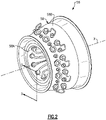
- the combustor 56 includes an array of fuel injectors 66 arranged about the longitudinal axis X, as illustrated by Figures 3 and 3A .
- Each fuel injector 66 is fluidly coupled to a fuel source FS.
- the fuel source FS is operable to supply fuel to each fuel injector 66 during engine operation.
- Each fuel injector 66 includes a fuel injector nozzle 67 that is operable to eject a quantity of fuel FF along a respective nozzle axis N.
- a projection of the nozzle axis N extends through the combustion chamber 64.
- a major component of the nozzle axis N extends in a direction that is parallel to the longitudinal axis X, as illustrated by Figure 3 .
- the combustor liners 60 are shown with the fuel injector nozzle 67 of Figure 3 removed for illustrative purposes.
- An injector mount 65 is dimensioned to receive a respective one of the nozzles 67 and extends along a respective nozzle axis N.
- the bulkhead 60C can define one or more apertures 61 (one shown for illustrative purposes) defined along the combustion chamber 64. Each aperture 61 is dimensioned to receive a respective fuel injector nozzle 67, as illustrated by Figure 3 .
- Each combustor liner 60A, 60B can include a liner support 69 that extends in the axial direction from the bulkhead 60C.
- Each liner segment 68 can be mounted or otherwise mechanically attached to the liner support 69 with one or more fasteners 73, for example.
- the liner support 69 can have a stepwise geometry, with the liner segments 68 arranged in the axial direction with respect to the longitudinal axis X to define a stepwise change in area of the combustion chamber 64 along the liner support 69. Adjacent liner segments 68 can axially overlap relative to the longitudinal axis X.
- Each liner segment 68 defines a cooling circuit 70 that conveys cooling flow CF to cool portions of the liner segment 68 and adjacent portions of the combustor 56, such as an adjacent (e.g., downstream) liner segment 68.
- the array of liner segments 68 can be arranged in the axial direction with respect to longitudinal axis X to define a step formation or stepwise change in area of the combustion chamber 64 such that each cooling circuit 70 of an upstream (or first) set of liner segments 68 is oriented to eject cooling flow CF from a respective trailing edge 68TE onto external surfaces of each external wall 68A of a downstream (or second) set of liner segments 68 bounding the combustion chamber 64, as illustrated by liner segments 68-1, 68-2.
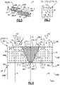
- Figure 6 illustrates a sectional view of one of the liner segments 68 defining a respective cooling circuit 70.
- the external wall 68A of the liner segment 68 is dimensioned to bound the combustion chamber 64.
- the external wall 68A extends between leading and trailing edges 68LE, 68TE in the axial direction and extends between opposing mate faces 68M in a circumferential direction with respect to the longitudinal axis X.
- Each of the liner segments 68 can have a substantially rectangular cross-sectional geometry.
- the external wall 68A is a portion of one of the inner and/or outer combustor liners 60A, 60B or bulkhead 60C ( Figures 3 and 4 ).
- the liner segment 68 can be one of the liner segments 68 of the inner combustion liner 60A.
- the liner segment 68 is the upstream liner segment 68-1 of outer combustion liner 60B positioned axially forward of axially aft liner segment 68-2 (shown in dashed lines for illustrative purposes).
- Liner segment 68-1 can be situated in a first, axially forwardmost row of the liner segments 68 relative to the fuel injector nozzles 67 and bulkhead 60C, as illustrated by Figures 3 and 4 , or can be situated in another one of the rows of liner segments 68 such as the second row of liner segments 68-2.
- the cooling circuits disclosed herein primarily refer to a combustor, other gas turbine engine components such as walls of the core flow path C in the turbine section 28 or mid-turbine frame 57 and other systems requiring cooling augmentation can benefit from the teachings disclosed herein.
- the cooling circuit 70 is defined by surfaces of the external wall 68A.
- the combustion chamber 64 and the cooling circuit 70 are on opposed sides of the external wall 68A.
- a thermal barrier coating 71 is disposed on surfaces of the external wall 68A (shown in dashed lines in Figure 5 for illustrated purposes).
- surfaces of the external wall 68A defining the combustion chamber 64 are substantially free of any cooling apertures along the cooling circuit 70.
- the liner segment 68 is circumferentially aligned with the nozzle axes N of two fuel injector nozzles 67.
- the projections of the nozzle axes N can be relatively closer to the mate faces 68M than arrangements having a liner segment circumferentially aligned with the nozzle axis of only one fuel injector nozzle, which may cause relatively greater thermal gradients to form across the liner segment 68 and non-uniform distribution of heat.
- the thermal gradients may cause the liner segment 68 to expand and distort during engine operation.
- the cooling circuits disclosed herein can be arranged to reduce the formation of thermal gradients across the liner segments.
- Liner segment 68 includes a plurality of heat transfer features 72 extending from the external wall 68A.
- the heat transfer features 72 are distributed in the cooling circuit 70 to interact with cooling flow CF for providing convective cooling to adjacent portions of the liner segment 68.
- the heat transfer features 72 extend in a radial direction with respect to the longitudinal axis X at least partially between opposed internal surfaces of the external wall 68A and liner support 69 that define the cooling circuit 70.
- heat transfer features 72 include pin-fins or pedestals that extend in the radial direction between the opposed internal surfaces of the external wall 68A and liner support 69 that define the cooling circuit 70.
- Each of the pedestals can have an elliptical geometry, as illustrated by Figure 6 .
- other geometries can be utilized such as rectangular, cube, diamond, oblong, teardrop, triangular or racetrack shaped cross-sectional geometries.
- the heat transfer features 72 are arranged in contiguous sets 72-1 through 72-3. Each of the respective sets 72-1 through 72-3 of heat transfer features 72 can be uniformly distributed, as illustrated by Figure 6 . In other examples, at least some of the heat transfer features 72' in the respective sets 72-1', 72-2' and/or 72-3' are non-uniformly distributed, as illustrated by Figure 7 .
- Each of the sets of heat transfer features 72-1, 72-2, 72-3 can be arranged relative to non-uniform boundary conditions such as heat concentrations or localized hotspots HS (shown in dashed lines in Figure 6 for illustrative purposes) that can form along the liner segment 68 during engine operation.
- formation of localized hot spots HS can occur due to ignition of fuel FF ejected by the nozzles 67.
- the hot spots HS can be generated or otherwise formed along the respective nozzle axes N.
- the hot spots HS typically have a relatively greater temperature than other portions of the liner segment 68 in operation, and in some scenarios can establish a peak temperature gradient relative to the liner segment 68.
- the distribution of heat transfer features 72 can reduce a likelihood of degradation of the liner segment 68 adjacent the hot spots HS that may otherwise occur due to excessive temperature exposure and insufficient cooling augmentation.
- the sets of heat transfer features 72-1 to 72-3 are distributed in the cooling circuit 70 to define at least one prioritized flow region and at least one restricted flow region to prioritize distribution of cooling flow CF in the cooling circuit 70.
- the cooling circuit 70 includes first and second prioritized flow regions 74-1, 74-2 that extend along and are defined on opposed sides of a first restricted flow region 74-3.
- the flow regions 74 can be dimensioned with respect to the location of each of the nozzle axes N.
- the heat transfer features 72 are arranged such that the prioritized flow regions 74-1, 74-2 extend along the projection of a respective one of the nozzle axes N, and the restricted flow region 74-3 is circumferentially spaced from the projection of each and every one of the nozzle axes N with respect to the longitudinal axis X.
- a concentration of heat transfer features 72 in each flow region 74 can be defined with respect to a volume of the cooling circuit 70 per unit area, which can be set by the shape, spacing, size and/or orientation of the heat transfer features 72.
- Each of the prioritized flow regions 74-1, 74-2 has a relatively lesser concentration of the heat transfer features 72 than the restricted flow region 74-3.
- An average concentration of heat transfer features 72 in the restricted flow region 74-3 differs in the circumferential direction from the prioritized flow regions 74-1, 74-2 for at least a majority of axial positions relative to the longitudinal axis X.
- the heat transfer features 72-3 in the restricted flow region 74-3 are more densely spaced than the heat transfer features 72-1, 72-2 in the prioritized flow regions 74-1, 74-2.
- the relative concentrations of the heat transfer features 72-1, 72-2, 72-3 can increase the amount of convective cooling to portions of the liner segment 68 adjacent the localized hot spots HS, even though the concentration of heat transfer features 72-1, 72-2 in the prioritized flow regions 74-1, 74-2 is less than the concentration of heat transfer features 72-3 in the restricted flow region 74-3.
- the sets of heat transfer features 72-1, 72-2, 72-3 establish respective perimeters P1, P2, P3 (shown in dashed lines) of the prioritized and restricted flow regions 74-1, 74-2, 74-3.
- the prioritized flow regions 74-1, 74-2 extend substantially from the leading edge 68LE to the trailing edge 68TE such that the perimeters P1, P2 are bounded by the perimeter P3 of the restricted flow region 74-3.
- the perimeters P1, P2 of the prioritized flow regions 74-1, 74-2 extend substantially along a respective one of the mate faces 68M.
- the term "substantially” means that the respective perimeter P1/P2/P3 is defined within an average distance of the respective heat transfer features 72-1/72-2/72-3 from the referenced component, such as the leading edge 68LE, mate faces 68M and/or trailing edge 68TE.
- the heat transfer features 72 can be dimensioned and arranged such that each of the prioritized flow regions 74-1, 74-2 has a relatively greater average flow path volume than the restricted flow region 74-3.
- the average flow path volume can be defined as a volume of the cooling circuit 70 within the respective perimeter P1, P2, P3 per unit area.
- each of the prioritized flow regions 74-1, 74-2 comprises at least 25% of a total flow path volume of the cooling circuit 70 in the liner segment 68, or more narrowly between 30% and 40% of the total flow path volume, with the restricted flow region 74-3 comprising a remainder of the total flow path volume.
- the prioritized flow regions 74-1, 74-2 have at least a quantity of three or four heat transfer features 72 per square inch for at least a majority of the cross sectional area of the respective prioritized flow regions 74-1, 74-2.
- the flow regions 74 can be dimensioned relative to the localized hot spots HS.
- the perimeter P3 of the restricted flow region 74-3 has a substantially trapezoidal (e.g., isosceles) geometry, with a width of the restricted flow region 74-3 generally increasing from the leading edge 68LE to the trailing edge 68TE.
- a first width W1 of the restricted flow region 74-3 adjacent the leading edge 68LE is greater than a second width W2 of the restricted flow region 74-3 adjacent the trailing edge 68TE such that at least a majority of the restricted flow region 74-3 progressively decreases in width or tapers from the leading edge 68LE to the trailing edge 68TE.
- the prioritized flow regions 74-1, 74-2 are axially aligned with the restricted flow region 74-3 for at least a majority, or more than 75% or 90%, of a length of the liner segment 68 between the leading and trailing edges 68LE, 68TE.
- the perimeters P1, P2 of the prioritized flow region 74-1, 74-2 extend between the axially forwardmost and axially aftmost heat transfer features 72 that are along or otherwise near the respective nozzle axes N.
- a width of each of the prioritized flow regions 74-1, 74-2 can generally increase from the leading to trailing edges 68LE, 68TE.
- a third width W3 of the first prioritized flow region 74-1 adjacent the leading edge 68LE is less than a fourth width W4 of the first prioritized flow region 74-1 adjacent the trailing edge 68TE.
- a fifth width W5 of the second prioritized flow region 74-2 adjacent the leading edge 68LE is less than a sixth width W6 of the second prioritized flow region 74-2 adjacent the trailing edge 68TE.
- Widths of the respective prioritized flow regions 74-1, 74-2 defining the perimeters P1, P2 can progressively increase from the leading edge 68LE to the trailing edge 68TE for at least a majority of the prioritized flow regions 74-1, 74-2.
- the difference in widths of the flow regions 74 relative to the leading and trailing edges 68LE, 68TE can increase diffusion of cooling flow CF ejected from the trailing edge 68TE toward an adjacent, downstream liner segment 68-2 (shown in dashed lines for illustrated purposes).
- the heat transfer features 72 can be distributed such that the cooling flow CF ejected along the trailing edge 68TE is diffused and substantially uniform in the circumferential direction when presented to the leading edge 68LE of the downstream liner segment 68-2, which can reduce a likelihood of formation of hot spots along the downstream liner segment 68-2.
- cooling flow CF is communicated to each of the flow regions 74.
- the cooling flow CF can be communicated at substantially the same temperature and/or pressure to each of the flow regions 74 adjacent to the leading edge 68LE, which serves as an inlet to the cooling circuit 70.
- the cooling flow CF circulates across the heat transfer features 72 to provide convective cooling to adjacent portions of the external wall 68A.
- the relative concentrations of the heat transfer features 72 in the flow regions 74 can cause at least a portion of the cooling flow CF in the restricted flow region 74-3 to be diverted or otherwise communicated from the restricted flow region 74-3 to an adjacent one of the prioritized flow regions 74-1, 74-2 due to pressure gradient(s) established by the distribution of the heat transfer features 72-1, 72-2, 72-3, with the prioritized flow regions 74-1, 74-2 operating at relatively lower pressures.
- the distribution of heat transfer features 72-3 establishes adverse pressure gradient(s) between the restricted flow region 74-3 and prioritized flow regions 74-1, 74-2, which opposes movement of the cooling flow CF from the prioritized flow regions 74-1, 74-2 into the restricted flow region 74-3.
- At least some of the cooling flow CF can circulate through the restricted flow region 74-3 and is then ejected from the restricted flow region 74-3 at the trailing edge 68TE.
- the concentration of heat transfer features 72 in each of the flow regions 74 promotes communication of relatively more cooling flow CF in the cooling circuit 70 along the nozzle axes N and toward the hot spot(s) HS, which can reduce a thermal gradient across the liner segment 68 and improve durability of the combustor liner 60 ( Figures 3 and 4 ).
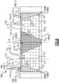
- FIG. 8 illustrates a combustor liner 160 according to the invention as defined by the claims.
- like reference numerals designate like elements where appropriate and reference numerals with the addition of one-hundred or multiples thereof designate modified elements that are understood to incorporate the same features and benefits of the corresponding original elements.
- the combustor liner 160 includes a plurality of liner segments 168 including liner segment 168-1 arranged circumferentially adjacent to liner segments 168-2, 168-3 (shown in dashed lines for illustrated purposes).
- Liner segment 168-1 defines a cooling circuit 170 including first and second prioritized flow regions 174-1, 174-2 that extend along opposed sides of restricted flow region 174-3.
- each mate face 168M of the liner segment 168-1 is arranged to define an intersegment gap G with the mate faces 168M of adjacent liner segments 168-2, 168-3.
- each intersegment gap G can be dimensioned to eject cooling flow CF radially inwardly or outwardly from the intersegment gap G into the combustor chamber 64 to provide cooling augmentation to portions of the liner segments 68 adj acent the mate faces 68M.
- Heat transfer features 172 are distributed in the cooling circuit 170 to define second and third restricted flow regions 174-4, 174-5 including respective sets of the heat transfer features 172-4, 172-5.
- Each of the second and third restricted flow regions 174-4, 174-5 extends along a respective one of the mate faces 168M and bounds a perimeter of a respective one of the prioritized flow regions 174-1, 174-2.
- Each of the perimeters P1, P2 of the prioritized flow regions 174-1, 174-2 has a substantially trapezoidal geometry, with a width of the prioritized flow regions 174-1, 174-2 generally increasing from leading edge 168LE to trailing edge 168TE.
- Perimeter P3 of the restricted flow region 174-3 has a substantially trapezoidal geometry.
- Perimeters P4, P5 of the restricted flow regions 174-4, 174-5 each have a substantially triangular geometry.
- a width of each of the restricted flow regions 174-4, 174-5 can be set (e.g., increased or decreased) to vary the amount of cooling flow CF communicated adjacent the mate faces 168M.
- Each of the second and third restricted flow regions 174-4, 174-5 has a relatively greater concentration of the heat transfer features 172 than an adjacent one of the prioritized flow regions 174-1, 174-2.
- the prioritized flow regions 174-1, 174-2 have a relatively greater average flow path volume than the restricted flow regions 174-3, 174-4, 174-5.
- the heat transfer features 172-4, 172-5 in the restricted flow regions 174-4, 174-5 can oppose or otherwise reduce the amount of cooling flow CF that is communicated from the prioritized flow regions 174-1, 174-2 toward the intersegment gaps G, which can reduce efficiency losses that may be otherwise caused by overcooling portions of the liner segments 168 adjacent to the mate faces 168M.
- the distribution of heat transfer features 172-4, 172-5 can be the same or can differ from the distribution of heat transfer features 172-3, including shape, spacing and/or orientation. In the illustrated example of Figure 8 , an average size of the heat transfer features 172-4, 172-5 is less than an average size of the heat transfer features 172-3, and an average spacing between the heat transfer features 172-4, 172-5 is greater than an average spacing between the heat transfer features 172-3.
- Figure 9 illustrates a liner segment 268 defining a cooling circuit 270 according to yet another example.
- Heat transfer features 272-1, 272-4, 272-5 are arranged to define restricted flow regions 274-4, 274-5 that extend along mate faces 268M and along opposed sides of prioritized flow region 274-1.
- Heat transfer features 272-1 have a relatively greater diameter and are less densely spaced than heat transfer features 274-4, 274-5 such that the prioritized flow region 274-1 has a relatively greater average flow path volume than the restricted flow regions 274-4, 274-5 to promote flow of cooling flow CF toward and along a projection of nozzle axis N.
- heat transfer features 372-1 have a substantially rectangular geometry, with a major component of a length of the heat transfer features 372-1 oriented in a circumferential direction with respect to a respective nozzle axis N and/or longitudinal axis X to oppose cooling flow CF.
- Heat transfer features 472A have a substantially cylindrical cross-sectional geometry.
- Heat transfer features 472B have an elliptical, non-circular geometry.
- Heat transfer features 472C have an elongated, substantially rectangular geometry.
- Heat transfer features 472D have a diamond shaped geometry.
- Heat transfer features 472E have a race track shaped geometry.
- Heat transfer features 472F have a teardrop shaped geometry.
- the arrangement of heat transfer features 472B, 472C can improve diffusion of cooling flow CF outwardly from trailing edge 468TE of liner segment 468 and reduce distress by orienting the cooling flow CF toward a localized hot spot of a downstream liner segment.
Landscapes
- Engineering & Computer Science (AREA)
- Chemical & Material Sciences (AREA)
- Combustion & Propulsion (AREA)
- Mechanical Engineering (AREA)
- General Engineering & Computer Science (AREA)
- Turbine Rotor Nozzle Sealing (AREA)
Claims (9)
- Brennkammerwand (60) für einen Gasturbinenmotor (20), umfassend:mindestens ein Wandsegment (68; 168) mit einer Außenwand (68A), die dimensioniert ist, dass sie einen Verbrennungsraum (64) begrenzt, wobei sich die Außenwand (68A) in einer axialen Richtung zwischen Vorder- und Hinterkanten (68LE, 68TE; 168LE, 168TE) erstreckt und in einer Umfangsrichtung zwischen gegenüberliegenden Passflächen (68M; 168M) erstreckt, wobei ein Kühlkreislauf (70; 170) durch die Außenwand (68A) definiert ist, eine Vielzahl von Wärmeübertragungselementen (72; 172) im Kühlkreislauf (70; 170) verteilt sind, um einen ersten Bereich (74-3; 174-3) mit eingeschränkter Strömung, der sich von der Vorderkante (68LE; 168LE) zur Hinterkante (68TE; 168TE) verjüngt, zu definieren, und um mindestens einen Bereich (74-1, 74-2; 174-1, 174-2) mit priorisierter Strömung, der sich im Wesentlichen von der Vorderkante (68LE; 168LE) zur Hinterkante (68TE; 168TE) erstreckt, zu definieren, sodass der mindestens eine Bereich (74-1, 74-2; 174-1, 174-2) mit priorisierter Strömung durch einen Umfang des ersten Bereichs (74-3; 174-3) mit eingeschränkter Strömung begrenzt ist, dadurch gekennzeichnet, dassjeder von dem mindestens einen Bereich (74-1, 74-2; 174-1, 174-2) mit priorisierter Strömung und dem ersten Bereich (74-3, 174-3) mit eingeschränkter Strömung eine Vielzahl der Wärmeübertragungselemente (72; 172) enthält, der mindestens eine Bereich (74-1, 74-2; 174-1, 174-2) mit priorisierter Strömung eine geringere Konzentration der Vielzahl von Wärmeübertragungselementen (72; 172) als der erste Bereich (74-3; 174-3) mit eingeschränkter Strömung aufweist, der mindestens eine Bereich (74-1, 74-2; 174-1, 174-2) mit priorisierter Strömung auf entgegengesetzten Seiten des ersten Bereichs (74-3; 174-3) mit eingeschränkter Strömung erste und zweite Bereiche (74-1, 74-2; 174-1, 174-2) mit priorisierter Strömung enthält, und die Vielzahl von Wärmeübertragungselementen (172) in dem Kühlkreislauf (170) verteilt sind, um zweite und dritte Bereiche (174-4, 174-5) mit eingeschränkter Strömung zu definieren, die sich im Wesentlichen entlang der Passflächen (168M) erstrecken, um jeweils einen von dem ersten und zweiten Bereich (174-1, 174-2) mit priorisierter Strömung zu begrenzen.
- Brennkammerwand nach Anspruch 1, wobei jeder von dem ersten und zweiten Bereich (174-1, 174-2) mit priorisierter Strömung eine im Wesentlichen trapezförmige Geometrie aufweist.
- Brennkammerwand nach Anspruch 1 oder 2, wobei das mindestens eine Wandsegment (68; 168) ein erstes Wandsegment (68; 168) und ein zweites Wandsegment (68; 168) enthält, die in axialer Richtung angeordnet sind, um eine schrittweise Änderung der Fläche des Verbrennungsraums (64) zu definieren, sodass der Kühlkreislauf (70; 170) des ersten Wandsegments (68; 168) so ausgerichtet ist, dass er einen Kühlstrom von der Hinterkante (68TE; 168TE) des ersten Wandsegments (68; 168) auf Außenflächen der Außenwand (68A) des zweiten Wandsegments (68; 168), das den Verbrennungsraum (64) definiert, ausstößt.
- Brennkammerwand nach einem der vorhergehenden Ansprüche, wobei das mindestens eine Wandsegment (68; 168) eine Anordnung von Wandsegmenten (68; 168) enthält und jede der Passflächen (68M; 168M) mit einem benachbarten der Wandsegmente (68; 168) einen Zwischensegmentspalt (G) definiert.
- Brennkammerwand nach einem der vorhergehenden Ansprüche, wobei die Vielzahl von Wärmeübertragungselementen (72; 172) eine Vielzahl von Sockeln enthält, die sich in einer radialen Richtung zwischen gegenüberliegenden Innenflächen, die den Kühlkreislauf (70; 170) definieren, erstrecken.
- Brennkammerwand nach einem der vorhergehenden Ansprüche, wobei jeweilige Sätze von der Vielzahl von Wärmeübertragungselementen (72; 172) gleichmäßig in dem ersten Bereich (74-3; 174-3) mit eingeschränkter Strömung und in dem mindestens einen Bereich (74-1, 74-2; 174-1, 174-2) mit priorisierter Strömung verteilt sind.
- Brennkammerwand nach einem der vorhergehenden Ansprüche, ferner umfassend eine thermische Sperrbeschichtung (71), die auf Oberflächen der Außenwand (68A), die den Verbrennungsraum (64) definiert, angeordnet ist.
- Brennkammerwand nach einem der vorhergehenden Ansprüche, wobei Oberflächen der Außenwand (68A), die den Verbrennungsraum (64) definieren, im Wesentlichen frei von Kühlöffnungen entlang des Kühlkreislaufs (70; 170) sind.
- Brennkammerwand nach einem der vorhergehenden Ansprüche, wobei die Außenwand (68A) eine Trennwand (60C) ist, die den Verbrennungsraum (64) in axialer Richtung begrenzt, und die Trennwand (60C) mindestens eine Öffnung (61) entlang des Verbrennungsraums (64) enthält, die so dimensioniert ist, dass sie eine Kraftstoffeinspritzdüse (67) aufnimmt.
Priority Applications (1)
| Application Number | Priority Date | Filing Date | Title |
|---|---|---|---|
| EP23153153.4A EP4191137B1 (de) | 2018-12-10 | 2019-12-10 | Brennkammerteil mit bevorzugtem strömungsverlauf |
Applications Claiming Priority (1)
| Application Number | Priority Date | Filing Date | Title |
|---|---|---|---|
| US16/214,824 US11125434B2 (en) | 2018-12-10 | 2018-12-10 | Preferential flow distribution for gas turbine engine component |
Related Child Applications (1)
| Application Number | Title | Priority Date | Filing Date |
|---|---|---|---|
| EP23153153.4A Division EP4191137B1 (de) | 2018-12-10 | 2019-12-10 | Brennkammerteil mit bevorzugtem strömungsverlauf |
Publications (2)
| Publication Number | Publication Date |
|---|---|
| EP3667167A1 EP3667167A1 (de) | 2020-06-17 |
| EP3667167B1 true EP3667167B1 (de) | 2023-01-25 |
Family
ID=68848175
Family Applications (2)
| Application Number | Title | Priority Date | Filing Date |
|---|---|---|---|
| EP23153153.4A Active EP4191137B1 (de) | 2018-12-10 | 2019-12-10 | Brennkammerteil mit bevorzugtem strömungsverlauf |
| EP19215043.1A Active EP3667167B1 (de) | 2018-12-10 | 2019-12-10 | Brennkammerwand für einen gasturbinenmotor |
Family Applications Before (1)
| Application Number | Title | Priority Date | Filing Date |
|---|---|---|---|
| EP23153153.4A Active EP4191137B1 (de) | 2018-12-10 | 2019-12-10 | Brennkammerteil mit bevorzugtem strömungsverlauf |
Country Status (2)
| Country | Link |
|---|---|
| US (2) | US11125434B2 (de) |
| EP (2) | EP4191137B1 (de) |
Families Citing this family (1)
| Publication number | Priority date | Publication date | Assignee | Title |
|---|---|---|---|---|
| CN116989354A (zh) | 2022-04-26 | 2023-11-03 | 通用电气公司 | 具有成形稀释开口的燃烧器衬里 |
Citations (1)
| Publication number | Priority date | Publication date | Assignee | Title |
|---|---|---|---|---|
| US20080145211A1 (en) * | 2006-12-19 | 2008-06-19 | Rolls-Royce Plc | Wall elements for gas turbine engine components |
Family Cites Families (14)
| Publication number | Priority date | Publication date | Assignee | Title |
|---|---|---|---|---|
| DE10248548A1 (de) * | 2002-10-18 | 2004-04-29 | Alstom (Switzerland) Ltd. | Kühlbares Bauteil |
| US7509809B2 (en) * | 2005-06-10 | 2009-03-31 | Pratt & Whitney Canada Corp. | Gas turbine engine combustor with improved cooling |
| GB0601413D0 (en) * | 2006-01-25 | 2006-03-08 | Rolls Royce Plc | Wall elements for gas turbine engine combustors |
| GB0601418D0 (en) * | 2006-01-25 | 2006-03-08 | Rolls Royce Plc | Wall elements for gas turbine engine combustors |
| US8356658B2 (en) * | 2006-07-27 | 2013-01-22 | General Electric Company | Heat transfer enhancing system and method for fabricating heat transfer device |
| CH700319A1 (de) * | 2009-01-30 | 2010-07-30 | Alstom Technology Ltd | Gekühltes bauelement für eine gasturbine. |
| US20120012284A1 (en) * | 2010-07-13 | 2012-01-19 | Alcatel-Lucent Usa Inc. | heat sink with staggered heat exchange elements |
| US20120304654A1 (en) | 2011-06-06 | 2012-12-06 | Melton Patrick Benedict | Combustion liner having turbulators |
| US8745988B2 (en) | 2011-09-06 | 2014-06-10 | Pratt & Whitney Canada Corp. | Pin fin arrangement for heat shield of gas turbine engine |
| EP2971668B1 (de) * | 2013-03-12 | 2019-05-22 | United Technologies Corporation | Aktive kühlung von tüllenstutzen für eine brennkammerauskleidung eines gasturbinenmotors |
| EP2846096A1 (de) | 2013-09-09 | 2015-03-11 | Siemens Aktiengesellschaft | Rohrbrennkammer mit einem Flammrohr-Endbereich und Gasturbine |
| WO2016099662A2 (en) | 2014-10-31 | 2016-06-23 | General Electric Company | Engine component assembly |
| US10746403B2 (en) * | 2014-12-12 | 2020-08-18 | Raytheon Technologies Corporation | Cooled wall assembly for a combustor and method of design |
| US20170089581A1 (en) | 2015-09-28 | 2017-03-30 | Pratt & Whitney Canada Corp. | Single skin combustor heat transfer augmenters |
-
2018
- 2018-12-10 US US16/214,824 patent/US11125434B2/en active Active
-
2019
- 2019-12-10 EP EP23153153.4A patent/EP4191137B1/de active Active
- 2019-12-10 EP EP19215043.1A patent/EP3667167B1/de active Active
-
2021
- 2021-08-30 US US17/460,520 patent/US11493205B2/en active Active
Patent Citations (1)
| Publication number | Priority date | Publication date | Assignee | Title |
|---|---|---|---|---|
| US20080145211A1 (en) * | 2006-12-19 | 2008-06-19 | Rolls-Royce Plc | Wall elements for gas turbine engine components |
Also Published As
| Publication number | Publication date |
|---|---|
| US11125434B2 (en) | 2021-09-21 |
| EP4191137A1 (de) | 2023-06-07 |
| EP3667167A1 (de) | 2020-06-17 |
| US11493205B2 (en) | 2022-11-08 |
| US20210388988A1 (en) | 2021-12-16 |
| US20200182464A1 (en) | 2020-06-11 |
| EP4191137B1 (de) | 2025-03-05 |
Similar Documents
| Publication | Publication Date | Title |
|---|---|---|
| EP3366995B1 (de) | Anordnung von brennkammerauskleidungsplatten und verfahren zu deren kühlung | |
| US11156359B2 (en) | Combustor liner panel end rail with diffused interface passage for a gas turbine engine combustor | |
| EP3077728B1 (de) | Gasturbinenbrennkammer mit co-swirl-ausrichtung von effusionslöchern, und methode | |
| US11781439B2 (en) | Seal arrangement for turbine engine component | |
| EP3366997B1 (de) | Merkmale zur kühlungsverbesserung von endschienen von brennkammerauskleidungsplatten für eine gasturbinenbrennkammer | |
| EP3366996A1 (de) | Abgewinkelter Kühlschnittstellendurchgang der Endschienen von Brennkammerauskleidungsplatten für eine Gasturbinebrennkammer | |
| US10774657B2 (en) | Baffle assembly for gas turbine engine components | |
| EP3330611B1 (de) | Reguliertes brennkammerwandpaneel für gasturbinenmotorbrennkammer | |
| EP3650648B1 (de) | Gekühlter gasturbinenartikel | |
| EP3667167B1 (de) | Brennkammerwand für einen gasturbinenmotor | |
| EP3321587B1 (de) | Axiale nichtlineare kontaktfläche für brennkammerverkleidungsplatten in einer gasturbinenbrennkammer | |
| US10001023B2 (en) | Grooved seal arrangement for turbine engine | |
| EP3557003B1 (de) | Dichtungssatz für gasturbinentriebwerk | |
| EP3321585B1 (de) | Nichtplanare brennkammerverkleidungsplatte für eine gasturbinenmotorbrennkammer | |
| EP3321584B1 (de) | Gasturbinenmotorbrennkammer mit einer axial-nichtplanaren brennkammerverkleidungsplatte | |
| EP3748131B1 (de) | Anordnung zur strömungslenkung von einer äussere laufschaufelluftdichtung (boas) |
Legal Events
| Date | Code | Title | Description |
|---|---|---|---|
| PUAI | Public reference made under article 153(3) epc to a published international application that has entered the european phase |
Free format text: ORIGINAL CODE: 0009012 |
|
| STAA | Information on the status of an ep patent application or granted ep patent |
Free format text: STATUS: THE APPLICATION HAS BEEN PUBLISHED |
|
| AK | Designated contracting states |
Kind code of ref document: A1 Designated state(s): AL AT BE BG CH CY CZ DE DK EE ES FI FR GB GR HR HU IE IS IT LI LT LU LV MC MK MT NL NO PL PT RO RS SE SI SK SM TR |
|
| AX | Request for extension of the european patent |
Extension state: BA ME |
|
| STAA | Information on the status of an ep patent application or granted ep patent |
Free format text: STATUS: REQUEST FOR EXAMINATION WAS MADE |
|
| 17P | Request for examination filed |
Effective date: 20201217 |
|
| RBV | Designated contracting states (corrected) |
Designated state(s): AL AT BE BG CH CY CZ DE DK EE ES FI FR GB GR HR HU IE IS IT LI LT LU LV MC MK MT NL NO PL PT RO RS SE SI SK SM TR |
|
| STAA | Information on the status of an ep patent application or granted ep patent |
Free format text: STATUS: EXAMINATION IS IN PROGRESS |
|
| 17Q | First examination report despatched |
Effective date: 20210205 |
|
| RAP1 | Party data changed (applicant data changed or rights of an application transferred) |
Owner name: RAYTHEON TECHNOLOGIES CORPORATION |
|
| GRAP | Despatch of communication of intention to grant a patent |
Free format text: ORIGINAL CODE: EPIDOSNIGR1 |
|
| STAA | Information on the status of an ep patent application or granted ep patent |
Free format text: STATUS: GRANT OF PATENT IS INTENDED |
|
| INTG | Intention to grant announced |
Effective date: 20220711 |
|
| GRAS | Grant fee paid |
Free format text: ORIGINAL CODE: EPIDOSNIGR3 |
|
| GRAA | (expected) grant |
Free format text: ORIGINAL CODE: 0009210 |
|
| STAA | Information on the status of an ep patent application or granted ep patent |
Free format text: STATUS: THE PATENT HAS BEEN GRANTED |
|
| AK | Designated contracting states |
Kind code of ref document: B1 Designated state(s): AL AT BE BG CH CY CZ DE DK EE ES FI FR GB GR HR HU IE IS IT LI LT LU LV MC MK MT NL NO PL PT RO RS SE SI SK SM TR |
|
| REG | Reference to a national code |
Ref country code: GB Ref legal event code: FG4D |
|
| REG | Reference to a national code |
Ref country code: CH Ref legal event code: EP |
|
| REG | Reference to a national code |
Ref country code: DE Ref legal event code: R096 Ref document number: 602019024750 Country of ref document: DE |
|
| REG | Reference to a national code |
Ref country code: AT Ref legal event code: REF Ref document number: 1546142 Country of ref document: AT Kind code of ref document: T Effective date: 20230215 Ref country code: IE Ref legal event code: FG4D |
|
| REG | Reference to a national code |
Ref country code: LT Ref legal event code: MG9D |
|
| REG | Reference to a national code |
Ref country code: NL Ref legal event code: MP Effective date: 20230125 |
|
| REG | Reference to a national code |
Ref country code: AT Ref legal event code: MK05 Ref document number: 1546142 Country of ref document: AT Kind code of ref document: T Effective date: 20230125 |
|
| P01 | Opt-out of the competence of the unified patent court (upc) registered |
Effective date: 20230521 |
|
| PG25 | Lapsed in a contracting state [announced via postgrant information from national office to epo] |
Ref country code: NL Free format text: LAPSE BECAUSE OF FAILURE TO SUBMIT A TRANSLATION OF THE DESCRIPTION OR TO PAY THE FEE WITHIN THE PRESCRIBED TIME-LIMIT Effective date: 20230125 |
|
| PG25 | Lapsed in a contracting state [announced via postgrant information from national office to epo] |
Ref country code: RS Free format text: LAPSE BECAUSE OF FAILURE TO SUBMIT A TRANSLATION OF THE DESCRIPTION OR TO PAY THE FEE WITHIN THE PRESCRIBED TIME-LIMIT Effective date: 20230125 Ref country code: PT Free format text: LAPSE BECAUSE OF FAILURE TO SUBMIT A TRANSLATION OF THE DESCRIPTION OR TO PAY THE FEE WITHIN THE PRESCRIBED TIME-LIMIT Effective date: 20230525 Ref country code: NO Free format text: LAPSE BECAUSE OF FAILURE TO SUBMIT A TRANSLATION OF THE DESCRIPTION OR TO PAY THE FEE WITHIN THE PRESCRIBED TIME-LIMIT Effective date: 20230425 Ref country code: LV Free format text: LAPSE BECAUSE OF FAILURE TO SUBMIT A TRANSLATION OF THE DESCRIPTION OR TO PAY THE FEE WITHIN THE PRESCRIBED TIME-LIMIT Effective date: 20230125 Ref country code: LT Free format text: LAPSE BECAUSE OF FAILURE TO SUBMIT A TRANSLATION OF THE DESCRIPTION OR TO PAY THE FEE WITHIN THE PRESCRIBED TIME-LIMIT Effective date: 20230125 Ref country code: HR Free format text: LAPSE BECAUSE OF FAILURE TO SUBMIT A TRANSLATION OF THE DESCRIPTION OR TO PAY THE FEE WITHIN THE PRESCRIBED TIME-LIMIT Effective date: 20230125 Ref country code: ES Free format text: LAPSE BECAUSE OF FAILURE TO SUBMIT A TRANSLATION OF THE DESCRIPTION OR TO PAY THE FEE WITHIN THE PRESCRIBED TIME-LIMIT Effective date: 20230125 Ref country code: AT Free format text: LAPSE BECAUSE OF FAILURE TO SUBMIT A TRANSLATION OF THE DESCRIPTION OR TO PAY THE FEE WITHIN THE PRESCRIBED TIME-LIMIT Effective date: 20230125 |
|
| PG25 | Lapsed in a contracting state [announced via postgrant information from national office to epo] |
Ref country code: SE Free format text: LAPSE BECAUSE OF FAILURE TO SUBMIT A TRANSLATION OF THE DESCRIPTION OR TO PAY THE FEE WITHIN THE PRESCRIBED TIME-LIMIT Effective date: 20230125 Ref country code: PL Free format text: LAPSE BECAUSE OF FAILURE TO SUBMIT A TRANSLATION OF THE DESCRIPTION OR TO PAY THE FEE WITHIN THE PRESCRIBED TIME-LIMIT Effective date: 20230125 Ref country code: IS Free format text: LAPSE BECAUSE OF FAILURE TO SUBMIT A TRANSLATION OF THE DESCRIPTION OR TO PAY THE FEE WITHIN THE PRESCRIBED TIME-LIMIT Effective date: 20230525 Ref country code: GR Free format text: LAPSE BECAUSE OF FAILURE TO SUBMIT A TRANSLATION OF THE DESCRIPTION OR TO PAY THE FEE WITHIN THE PRESCRIBED TIME-LIMIT Effective date: 20230426 Ref country code: FI Free format text: LAPSE BECAUSE OF FAILURE TO SUBMIT A TRANSLATION OF THE DESCRIPTION OR TO PAY THE FEE WITHIN THE PRESCRIBED TIME-LIMIT Effective date: 20230125 |
|
| REG | Reference to a national code |
Ref country code: DE Ref legal event code: R097 Ref document number: 602019024750 Country of ref document: DE |
|
| PG25 | Lapsed in a contracting state [announced via postgrant information from national office to epo] |
Ref country code: SM Free format text: LAPSE BECAUSE OF FAILURE TO SUBMIT A TRANSLATION OF THE DESCRIPTION OR TO PAY THE FEE WITHIN THE PRESCRIBED TIME-LIMIT Effective date: 20230125 Ref country code: RO Free format text: LAPSE BECAUSE OF FAILURE TO SUBMIT A TRANSLATION OF THE DESCRIPTION OR TO PAY THE FEE WITHIN THE PRESCRIBED TIME-LIMIT Effective date: 20230125 Ref country code: EE Free format text: LAPSE BECAUSE OF FAILURE TO SUBMIT A TRANSLATION OF THE DESCRIPTION OR TO PAY THE FEE WITHIN THE PRESCRIBED TIME-LIMIT Effective date: 20230125 Ref country code: DK Free format text: LAPSE BECAUSE OF FAILURE TO SUBMIT A TRANSLATION OF THE DESCRIPTION OR TO PAY THE FEE WITHIN THE PRESCRIBED TIME-LIMIT Effective date: 20230125 Ref country code: CZ Free format text: LAPSE BECAUSE OF FAILURE TO SUBMIT A TRANSLATION OF THE DESCRIPTION OR TO PAY THE FEE WITHIN THE PRESCRIBED TIME-LIMIT Effective date: 20230125 |
|
| RAP4 | Party data changed (patent owner data changed or rights of a patent transferred) |
Owner name: RTX CORPORATION |
|
| PG25 | Lapsed in a contracting state [announced via postgrant information from national office to epo] |
Ref country code: SK Free format text: LAPSE BECAUSE OF FAILURE TO SUBMIT A TRANSLATION OF THE DESCRIPTION OR TO PAY THE FEE WITHIN THE PRESCRIBED TIME-LIMIT Effective date: 20230125 |
|
| PLBE | No opposition filed within time limit |
Free format text: ORIGINAL CODE: 0009261 |
|
| STAA | Information on the status of an ep patent application or granted ep patent |
Free format text: STATUS: NO OPPOSITION FILED WITHIN TIME LIMIT |
|
| 26N | No opposition filed |
Effective date: 20231026 |
|
| PG25 | Lapsed in a contracting state [announced via postgrant information from national office to epo] |
Ref country code: SI Free format text: LAPSE BECAUSE OF FAILURE TO SUBMIT A TRANSLATION OF THE DESCRIPTION OR TO PAY THE FEE WITHIN THE PRESCRIBED TIME-LIMIT Effective date: 20230125 |
|
| PG25 | Lapsed in a contracting state [announced via postgrant information from national office to epo] |
Ref country code: IT Free format text: LAPSE BECAUSE OF FAILURE TO SUBMIT A TRANSLATION OF THE DESCRIPTION OR TO PAY THE FEE WITHIN THE PRESCRIBED TIME-LIMIT Effective date: 20230125 |
|
| REG | Reference to a national code |
Ref country code: CH Ref legal event code: PL |
|
| PG25 | Lapsed in a contracting state [announced via postgrant information from national office to epo] |
Ref country code: LU Free format text: LAPSE BECAUSE OF NON-PAYMENT OF DUE FEES Effective date: 20231210 |
|
| PG25 | Lapsed in a contracting state [announced via postgrant information from national office to epo] |
Ref country code: MC Free format text: LAPSE BECAUSE OF FAILURE TO SUBMIT A TRANSLATION OF THE DESCRIPTION OR TO PAY THE FEE WITHIN THE PRESCRIBED TIME-LIMIT Effective date: 20230125 |
|
| REG | Reference to a national code |
Ref country code: BE Ref legal event code: MM Effective date: 20231231 |
|
| PG25 | Lapsed in a contracting state [announced via postgrant information from national office to epo] |
Ref country code: MC Free format text: LAPSE BECAUSE OF FAILURE TO SUBMIT A TRANSLATION OF THE DESCRIPTION OR TO PAY THE FEE WITHIN THE PRESCRIBED TIME-LIMIT Effective date: 20230125 Ref country code: LU Free format text: LAPSE BECAUSE OF NON-PAYMENT OF DUE FEES Effective date: 20231210 |
|
| REG | Reference to a national code |
Ref country code: IE Ref legal event code: MM4A |
|
| PG25 | Lapsed in a contracting state [announced via postgrant information from national office to epo] |
Ref country code: IE Free format text: LAPSE BECAUSE OF NON-PAYMENT OF DUE FEES Effective date: 20231210 |
|
| PG25 | Lapsed in a contracting state [announced via postgrant information from national office to epo] |
Ref country code: BE Free format text: LAPSE BECAUSE OF NON-PAYMENT OF DUE FEES Effective date: 20231231 |
|
| PG25 | Lapsed in a contracting state [announced via postgrant information from national office to epo] |
Ref country code: CH Free format text: LAPSE BECAUSE OF NON-PAYMENT OF DUE FEES Effective date: 20231231 |
|
| PG25 | Lapsed in a contracting state [announced via postgrant information from national office to epo] |
Ref country code: IE Free format text: LAPSE BECAUSE OF NON-PAYMENT OF DUE FEES Effective date: 20231210 Ref country code: CH Free format text: LAPSE BECAUSE OF NON-PAYMENT OF DUE FEES Effective date: 20231231 Ref country code: BE Free format text: LAPSE BECAUSE OF NON-PAYMENT OF DUE FEES Effective date: 20231231 |
|
| PG25 | Lapsed in a contracting state [announced via postgrant information from national office to epo] |
Ref country code: BG Free format text: LAPSE BECAUSE OF FAILURE TO SUBMIT A TRANSLATION OF THE DESCRIPTION OR TO PAY THE FEE WITHIN THE PRESCRIBED TIME-LIMIT Effective date: 20230125 |
|
| PG25 | Lapsed in a contracting state [announced via postgrant information from national office to epo] |
Ref country code: BG Free format text: LAPSE BECAUSE OF FAILURE TO SUBMIT A TRANSLATION OF THE DESCRIPTION OR TO PAY THE FEE WITHIN THE PRESCRIBED TIME-LIMIT Effective date: 20230125 |
|
| PG25 | Lapsed in a contracting state [announced via postgrant information from national office to epo] |
Ref country code: CY Free format text: LAPSE BECAUSE OF FAILURE TO SUBMIT A TRANSLATION OF THE DESCRIPTION OR TO PAY THE FEE WITHIN THE PRESCRIBED TIME-LIMIT; INVALID AB INITIO Effective date: 20191210 |
|
| PG25 | Lapsed in a contracting state [announced via postgrant information from national office to epo] |
Ref country code: HU Free format text: LAPSE BECAUSE OF FAILURE TO SUBMIT A TRANSLATION OF THE DESCRIPTION OR TO PAY THE FEE WITHIN THE PRESCRIBED TIME-LIMIT; INVALID AB INITIO Effective date: 20191210 |
|
| REG | Reference to a national code |
Ref country code: DE Ref legal event code: R081 Ref document number: 602019024750 Country of ref document: DE Owner name: RTX CORPORATION (N.D.GES.D. STAATES DELAWARE),, US Free format text: FORMER OWNER: RAYTHEON TECHNOLOGIES CORPORATION, FARMINGTON, CT, US |
|
| PG25 | Lapsed in a contracting state [announced via postgrant information from national office to epo] |
Ref country code: TR Free format text: LAPSE BECAUSE OF FAILURE TO SUBMIT A TRANSLATION OF THE DESCRIPTION OR TO PAY THE FEE WITHIN THE PRESCRIBED TIME-LIMIT Effective date: 20230125 |
|
| PGFP | Annual fee paid to national office [announced via postgrant information from national office to epo] |
Ref country code: DE Payment date: 20251126 Year of fee payment: 7 |
|
| PGFP | Annual fee paid to national office [announced via postgrant information from national office to epo] |
Ref country code: GB Payment date: 20251119 Year of fee payment: 7 |
|
| PGFP | Annual fee paid to national office [announced via postgrant information from national office to epo] |
Ref country code: FR Payment date: 20251120 Year of fee payment: 7 |