EP3667167A1 - Preferential flow distribution for gas turbine engine component - Google Patents
Preferential flow distribution for gas turbine engine component Download PDFInfo
- Publication number
- EP3667167A1 EP3667167A1 EP19215043.1A EP19215043A EP3667167A1 EP 3667167 A1 EP3667167 A1 EP 3667167A1 EP 19215043 A EP19215043 A EP 19215043A EP 3667167 A1 EP3667167 A1 EP 3667167A1
- Authority
- EP
- European Patent Office
- Prior art keywords
- liner
- prioritized
- combustor
- combustion chamber
- flow region
- Prior art date
- Legal status (The legal status is an assumption and is not a legal conclusion. Google has not performed a legal analysis and makes no representation as to the accuracy of the status listed.)
- Granted
Links
- 238000009826 distribution Methods 0.000 title description 9
- 238000001816 cooling Methods 0.000 claims abstract description 91
- 238000012546 transfer Methods 0.000 claims abstract description 77
- 238000002485 combustion reaction Methods 0.000 claims abstract description 48
- 239000000446 fuel Substances 0.000 claims description 41
- 230000008859 change Effects 0.000 claims description 7
- 239000012720 thermal barrier coating Substances 0.000 claims description 3
- 239000007789 gas Substances 0.000 description 13
- 230000015572 biosynthetic process Effects 0.000 description 5
- 230000008901 benefit Effects 0.000 description 4
- 230000003416 augmentation Effects 0.000 description 3
- 239000000567 combustion gas Substances 0.000 description 2
- 238000004891 communication Methods 0.000 description 2
- 229910003460 diamond Inorganic materials 0.000 description 2
- 239000010432 diamond Substances 0.000 description 2
- 238000009792 diffusion process Methods 0.000 description 2
- 230000009467 reduction Effects 0.000 description 2
- 230000003068 static effect Effects 0.000 description 2
- 238000011144 upstream manufacturing Methods 0.000 description 2
- 230000002411 adverse Effects 0.000 description 1
- 230000015556 catabolic process Effects 0.000 description 1
- 230000006835 compression Effects 0.000 description 1
- 238000007906 compression Methods 0.000 description 1
- 238000012937 correction Methods 0.000 description 1
- 239000013078 crystal Substances 0.000 description 1
- 230000007423 decrease Effects 0.000 description 1
- 230000003247 decreasing effect Effects 0.000 description 1
- 238000006731 degradation reaction Methods 0.000 description 1
- 230000009429 distress Effects 0.000 description 1
- 239000000463 material Substances 0.000 description 1
- 230000007246 mechanism Effects 0.000 description 1
- 239000002184 metal Substances 0.000 description 1
- 229910001092 metal group alloy Inorganic materials 0.000 description 1
- 238000012986 modification Methods 0.000 description 1
- 230000004048 modification Effects 0.000 description 1
- 238000009828 non-uniform distribution Methods 0.000 description 1
- 230000004044 response Effects 0.000 description 1
Images


Classifications
-
- F—MECHANICAL ENGINEERING; LIGHTING; HEATING; WEAPONS; BLASTING
- F23—COMBUSTION APPARATUS; COMBUSTION PROCESSES
- F23R—GENERATING COMBUSTION PRODUCTS OF HIGH PRESSURE OR HIGH VELOCITY, e.g. GAS-TURBINE COMBUSTION CHAMBERS
- F23R3/00—Continuous combustion chambers using liquid or gaseous fuel
- F23R3/02—Continuous combustion chambers using liquid or gaseous fuel characterised by the air-flow or gas-flow configuration
- F23R3/04—Air inlet arrangements
- F23R3/06—Arrangement of apertures along the flame tube
- F23R3/08—Arrangement of apertures along the flame tube between annular flame tube sections, e.g. flame tubes with telescopic sections
-
- F—MECHANICAL ENGINEERING; LIGHTING; HEATING; WEAPONS; BLASTING
- F23—COMBUSTION APPARATUS; COMBUSTION PROCESSES
- F23R—GENERATING COMBUSTION PRODUCTS OF HIGH PRESSURE OR HIGH VELOCITY, e.g. GAS-TURBINE COMBUSTION CHAMBERS
- F23R3/00—Continuous combustion chambers using liquid or gaseous fuel
- F23R3/002—Wall structures
-
- F—MECHANICAL ENGINEERING; LIGHTING; HEATING; WEAPONS; BLASTING
- F23—COMBUSTION APPARATUS; COMBUSTION PROCESSES
- F23R—GENERATING COMBUSTION PRODUCTS OF HIGH PRESSURE OR HIGH VELOCITY, e.g. GAS-TURBINE COMBUSTION CHAMBERS
- F23R3/00—Continuous combustion chambers using liquid or gaseous fuel
- F23R3/02—Continuous combustion chambers using liquid or gaseous fuel characterised by the air-flow or gas-flow configuration
- F23R3/04—Air inlet arrangements
- F23R3/06—Arrangement of apertures along the flame tube
-
- F—MECHANICAL ENGINEERING; LIGHTING; HEATING; WEAPONS; BLASTING
- F23—COMBUSTION APPARATUS; COMBUSTION PROCESSES
- F23R—GENERATING COMBUSTION PRODUCTS OF HIGH PRESSURE OR HIGH VELOCITY, e.g. GAS-TURBINE COMBUSTION CHAMBERS
- F23R3/00—Continuous combustion chambers using liquid or gaseous fuel
- F23R3/02—Continuous combustion chambers using liquid or gaseous fuel characterised by the air-flow or gas-flow configuration
- F23R3/26—Controlling the air flow
-
- F—MECHANICAL ENGINEERING; LIGHTING; HEATING; WEAPONS; BLASTING
- F23—COMBUSTION APPARATUS; COMBUSTION PROCESSES
- F23R—GENERATING COMBUSTION PRODUCTS OF HIGH PRESSURE OR HIGH VELOCITY, e.g. GAS-TURBINE COMBUSTION CHAMBERS
- F23R3/00—Continuous combustion chambers using liquid or gaseous fuel
- F23R3/42—Continuous combustion chambers using liquid or gaseous fuel characterised by the arrangement or form of the flame tubes or combustion chambers
- F23R3/50—Combustion chambers comprising an annular flame tube within an annular casing
-
- F—MECHANICAL ENGINEERING; LIGHTING; HEATING; WEAPONS; BLASTING
- F23—COMBUSTION APPARATUS; COMBUSTION PROCESSES
- F23R—GENERATING COMBUSTION PRODUCTS OF HIGH PRESSURE OR HIGH VELOCITY, e.g. GAS-TURBINE COMBUSTION CHAMBERS
- F23R3/00—Continuous combustion chambers using liquid or gaseous fuel
- F23R3/42—Continuous combustion chambers using liquid or gaseous fuel characterised by the arrangement or form of the flame tubes or combustion chambers
- F23R3/60—Support structures; Attaching or mounting means
-
- F—MECHANICAL ENGINEERING; LIGHTING; HEATING; WEAPONS; BLASTING
- F23—COMBUSTION APPARATUS; COMBUSTION PROCESSES
- F23R—GENERATING COMBUSTION PRODUCTS OF HIGH PRESSURE OR HIGH VELOCITY, e.g. GAS-TURBINE COMBUSTION CHAMBERS
- F23R2900/00—Special features of, or arrangements for continuous combustion chambers; Combustion processes therefor
- F23R2900/03043—Convection cooled combustion chamber walls with means for guiding the cooling air flow
-
- F—MECHANICAL ENGINEERING; LIGHTING; HEATING; WEAPONS; BLASTING
- F23—COMBUSTION APPARATUS; COMBUSTION PROCESSES
- F23R—GENERATING COMBUSTION PRODUCTS OF HIGH PRESSURE OR HIGH VELOCITY, e.g. GAS-TURBINE COMBUSTION CHAMBERS
- F23R2900/00—Special features of, or arrangements for continuous combustion chambers; Combustion processes therefor
- F23R2900/03044—Impingement cooled combustion chamber walls or subassemblies
-
- F—MECHANICAL ENGINEERING; LIGHTING; HEATING; WEAPONS; BLASTING
- F23—COMBUSTION APPARATUS; COMBUSTION PROCESSES
- F23R—GENERATING COMBUSTION PRODUCTS OF HIGH PRESSURE OR HIGH VELOCITY, e.g. GAS-TURBINE COMBUSTION CHAMBERS
- F23R2900/00—Special features of, or arrangements for continuous combustion chambers; Combustion processes therefor
- F23R2900/03045—Convection cooled combustion chamber walls provided with turbolators or means for creating turbulences to increase cooling
-
- Y—GENERAL TAGGING OF NEW TECHNOLOGICAL DEVELOPMENTS; GENERAL TAGGING OF CROSS-SECTIONAL TECHNOLOGIES SPANNING OVER SEVERAL SECTIONS OF THE IPC; TECHNICAL SUBJECTS COVERED BY FORMER USPC CROSS-REFERENCE ART COLLECTIONS [XRACs] AND DIGESTS
- Y02—TECHNOLOGIES OR APPLICATIONS FOR MITIGATION OR ADAPTATION AGAINST CLIMATE CHANGE
- Y02T—CLIMATE CHANGE MITIGATION TECHNOLOGIES RELATED TO TRANSPORTATION
- Y02T50/00—Aeronautics or air transport
- Y02T50/60—Efficient propulsion technologies, e.g. for aircraft
Landscapes
- Engineering & Computer Science (AREA)
- Chemical & Material Sciences (AREA)
- Combustion & Propulsion (AREA)
- Mechanical Engineering (AREA)
- General Engineering & Computer Science (AREA)
- Turbine Rotor Nozzle Sealing (AREA)
Abstract
Description
- This disclosure relates to a combustor for a gas turbine engine and, more particularly, to flow distribution through a combustor liner of the combustor.
- Gas turbine engines can include a fan for propulsion air and to cool components. The fan also delivers air into a core engine where it is compressed. The compressed air is then delivered into a combustor section.
- The combustor section includes one or more combustor liners that define a combustion chamber. Fuel is ejected from fuel injectors into the combustion chamber. The compressed air is mixed with the fuel and ignited in the combustion chamber to produce relatively hot combustion gases. The combustion gases expand downstream over and drive turbine blades.
- The combustor liners are subject to extreme heat due to the combustion process. Formation of hot spots can occur along localized regions of the combustor liners. Cooling flow may be utilized to cool portions of the combustor liners at locations adjacent to the hot spots.
- A combustor liner for a gas turbine engine according to a first aspect of the present disclosure includes at least one liner segment that has an external wall dimensioned to bound a combustion chamber. The external wall extends between leading and trailing edges in an axial direction and extends between opposed mate faces in a circumferential direction. A cooling circuit is defined by the external wall. A plurality of heat transfer features are distributed in the cooling circuit to define a first restricted flow region that tapers from the leading edge to the trailing edge and to define at least one prioritized flow region that extends substantially from the leading edge to the trailing edge such that the at least one prioritized flow region is bounded by a perimeter of the first restricted flow region, and the at least one prioritized flow region has a lesser concentration of the plurality of heat transfer features than the first restricted flow region.
- In an embodiment of the foregoing, the at least one prioritized flow region includes first and second prioritized flow regions on opposed sides of the first restricted flow region.
- In a further embodiment of any of the foregoing embodiments, the plurality of heat transfer features are distributed in the cooling circuit to define second and third restricted flow regions that extend substantially along the mate faces to bound respective ones of the first and second prioritized flow regions.
- In a further embodiment of any of the foregoing embodiments, each of the first and second prioritized flow regions has a substantially trapezoidal geometry.
- In a further embodiment of any of the foregoing embodiments, the at least one liner segment includes a first liner segment and a second liner segment arranged in the axial direction to define a stepwise change in area of the combustion chamber such that the cooling circuit of the first liner segment is oriented to eject cooling flow from the trailing edge of the first liner segment onto external surfaces of the external wall of the second liner segment that defines the combustion chamber.
- In a further embodiment of any of the foregoing embodiments, the at least one liner segment includes an array of liner segments, and each of the mate faces defines an intersegment gap with an adjacent one of the liner segments.
- In a further embodiment of any of the foregoing embodiments, the plurality of heat transfer features includes a plurality of pedestals that extend in a radial direction between opposed internal surfaces defining the cooling circuit.
- In a further embodiment of any of the foregoing embodiments, respective sets of the plurality of heat transfer features are uniformly distributed in the first restricted flow region and in the at least one prioritized flow region.
- A further embodiment of any of the foregoing embodiments includes a thermal barrier coating disposed on surfaces of the external wall defining the combustion chamber.
- In a further embodiment of any of the foregoing embodiments, the surfaces of the external wall defining the combustion chamber are substantially free of any cooling apertures along the cooling circuit.
- In a further embodiment of any of the foregoing embodiments, the external wall is a bulkhead that bounds the combustion chamber in the axial direction. The bulkhead has at least one aperture along the combustion chamber that is dimensioned to receive a fuel injector nozzle.
- A combustor section for a gas turbine engine according to another aspect of the present disclosure includes an array of fuel injector nozzles arranged about a longitudinal axis. A combustor liner includes an array of liner segments arranged about the longitudinal axis to define a combustion chamber. Each one of the fuel injector nozzles defines a nozzle axis. A projection of the nozzle axis extends through the combustion chamber. Each one of the liner segments includes an external wall extending axially between leading and trailing edges and extending circumferentially between opposed mate faces with respect to the longitudinal axis. A cooling circuit is defined by the external wall. A plurality of heat transfer features are distributed in the cooling circuit to define first and second prioritized flow regions on opposed sides of a first restricted flow region. Each of the first and second prioritized flow regions extend axially along the projection of the nozzle axis of respective ones of the fuel injector nozzles from the leading edge to the trailing edge such that the first restricted flow region tapers from the leading edge to the trailing edge, and each of the first and second prioritized flow regions have a relatively greater average flow path volume than the first restricted flow region.
- In an embodiment of the foregoing, the plurality of heat transfer features are distributed in the cooling circuit to define second and third restricted flow regions that extend substantially along the mate faces to bound a perimeter of respective ones of the first and second prioritized flow regions, and each of the first and second prioritized flow regions has a relatively greater average flow path volume than the second and third restricted flow regions.
- In a further embodiment of any of the foregoing embodiments, surfaces of the external wall defining the combustion chamber are substantially free of any cooling apertures along the cooling circuit.
- A gas turbine engine according to another aspect of the present disclosure includes a compressor section, a turbine section that drives the compressor section, a combustor section has a combustor. The combustor has a combustor liner and an array of fuel injector nozzles arranged about an engine longitudinal axis. The combustor liner has an array of liner segments arranged about the engine longitudinal axis to define a combustion chamber. Each one of the fuel injector nozzles defines a nozzle axis. A projection of the nozzle axis extends through the combustion chamber. Each one of the liner segments includes an external wall extending axially between leading and trailing edges and extending circumferentially between opposed mate faces with respect to the engine longitudinal axis. A cooling circuit is defined by the external wall. A plurality of heat transfer features are distributed in the cooling circuit to define first and second prioritized flow regions on opposed sides of a first restricted flow region. Each of the first and second prioritized flow regions extend axially along the projection of the nozzle axis of respective ones of the fuel injector nozzles such that a width of the first and second prioritized flow regions progressively increases from the leading edge to the trailing edge.
- In an embodiment of the foregoing, the first restricted flow region is circumferentially spaced from the projection of the nozzle axis of each and every one of the fuel injector nozzles.
- In a further embodiment of any of the foregoing embodiments, the first restricted flow region tapers from the leading edge to the trailing edge.
- In a further embodiment of any of the foregoing embodiments each of the mate faces defines an intersegment gap with the mate face of an adj acent one of the liner segments. The plurality of heat transfer features are distributed in the cooling circuit to define second and third restricted flow regions that extend substantially along the mate faces to bound a perimeter of respective ones of the first and second prioritized flow regions.
- In a further embodiment of any of the foregoing embodiments, the intersegment gap is dimensioned to eject cooling flow into the combustion chamber.
- In a further embodiment of any of the foregoing embodiments, the array of liner segments includes a first set of liner segments and a second set of liner segments axially arranged to define a stepwise change in area of the combustion chamber such that each cooling circuit of the first set of liner segments is oriented to eject cooling flow onto external surfaces of the second set of liner segments bounding the combustion chamber.
- The various features and advantages of this invention will become apparent to those skilled in the art from the following detailed description of an embodiment. The drawings that accompany the detailed description can be briefly described as follows.
-
-
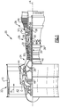
Figure 1 schematically shows a gas turbine engine. -
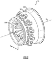
Figure 2 is a perspective view of a combustor. -
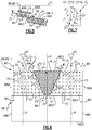
Figure 3 is a sectional view of the combustor taken along line 3-3 ofFigure 2 . -
Figure 3A schematically illustrates the combustor taken alongline 3A-3A ofFigure 3 . -
Figure 4 is a sectional view of the combustor ofFigure 3 with a fuel injector nozzle uninstalled. -
Figure 5 is a sectional view of adjacent liner segments of the combustor ofFigure 3 . -
Figure 6 is a sectional view of the liner segments taken along line 6-6 ofFigure 5 . -
Figure 7 illustrates an example distribution of heat transfer features. -
Figure 8 is a sectional view of a liner segment according to another example. -
Figure 9 is a sectional view of a liner segment arranged relative to a fuel injector nozzle according to yet another example. -
Figure 10 is a sectional view of a liner segment arranged relative to a fuel injector nozzle according to yet another example. -
Figure 11 illustrates example geometries of heat transfer features. -
Figure 1 schematically illustrates agas turbine engine 20. Thegas turbine engine 20 is disclosed herein as a two-spool turbofan that generally incorporates afan section 22, acompressor section 24, acombustor section 26 and aturbine section 28. Thefan section 22 drives air along a bypass flow path B in a bypass duct defined within anacelle 15, and also drives air along a core flow path C for compression and communication into thecombustor section 26 then expansion through theturbine section 28. Although depicted as a two-spool turbofan gas turbine engine in the disclosed non-limiting embodiment, it should be understood that the concepts described herein are not limited to use with two-spool turbofans as the teachings may be applied to other types of turbine engines including three-spool architectures. - The
exemplary engine 20 generally includes alow speed spool 30 and ahigh speed spool 32 mounted for rotation about an engine central longitudinal axis A relative to an enginestatic structure 36 viaseveral bearing systems 38. It should be understood that various bearingsystems 38 at various locations may alternatively or additionally be provided, and the location of bearingsystems 38 may be varied as appropriate to the application. - The
low speed spool 30 generally includes aninner shaft 40 that interconnects, a first (or low)pressure compressor 44 and a first (or low)pressure turbine 46. Theinner shaft 40 is connected to thefan 42 through a speed change mechanism, which in exemplarygas turbine engine 20 is illustrated as a geared architecture 48 to drive afan 42 at a lower speed than thelow speed spool 30. Thehigh speed spool 32 includes anouter shaft 50 that interconnects a second (or high)pressure compressor 52 and a second (or high)pressure turbine 54. Acombustor 56 is arranged inexemplary gas turbine 20 between thehigh pressure compressor 52 and thehigh pressure turbine 54. Amid-turbine frame 57 of the enginestatic structure 36 may be arranged generally between thehigh pressure turbine 54 and thelow pressure turbine 46. Themid-turbine frame 57 furthersupports bearing systems 38 in theturbine section 28. Theinner shaft 40 and theouter shaft 50 are concentric and rotate via bearingsystems 38 about the engine central longitudinal axis A which is collinear with their longitudinal axes. - The core airflow is compressed by the
low pressure compressor 44 then thehigh pressure compressor 52, mixed and burned with fuel in thecombustor 56, then expanded over thehigh pressure turbine 54 andlow pressure turbine 46. Themid-turbine frame 57 includesairfoils 59 which are in the core airflow path C. Theturbines low speed spool 30 andhigh speed spool 32 in response to the expansion. It will be appreciated that each of the positions of thefan section 22,compressor section 24,combustor section 26,turbine section 28, and fan drive gear system 48 may be varied. For example, gear system 48 may be located aft of the low pressure compressor, or aft of thecombustor section 26 or even aft ofturbine section 28, andfan 42 may be positioned forward or aft of the location of gear system 48. - The
engine 20 in one example is a high-bypass geared aircraft engine. In a further example, theengine 20 bypass ratio is greater than about six, with an example embodiment being greater than about ten, the geared architecture 48 is an epicyclic gear train, such as a planetary gear system or other gear system, with a gear reduction ratio of greater than about 2.3 and thelow pressure turbine 46 has a pressure ratio that is greater than about five. In one disclosed embodiment, theengine 20 bypass ratio is greater than about ten, the fan diameter is significantly larger than that of thelow pressure compressor 44, and thelow pressure turbine 46 has a pressure ratio that is greater than about five.Low pressure turbine 46 pressure ratio is pressure measured prior to inlet oflow pressure turbine 46 as related to the pressure at the outlet of thelow pressure turbine 46 prior to an exhaust nozzle. The geared architecture 48 may be an epicycle gear train, such as a planetary gear system or other gear system, with a gear reduction ratio of greater than about 2.3:1 and less than about 5:1. It should be understood, however, that the above parameters are only exemplary of one embodiment of a geared architecture engine and that the present invention is applicable to other gas turbine engines including direct drive turbofans. - A significant amount of thrust is provided by the bypass flow B due to the high bypass ratio. The
fan section 22 of theengine 20 is designed for a particular flight condition -- typically cruise at about 0.8 Mach and about 35,000 feet (10,668 meters). The flight condition of 0.8 Mach and 35,000 ft (10,668 meters), with the engine at its best fuel consumption - also known as "bucket cruise Thrust Specific Fuel Consumption ('TSFC')" - is the industry standard parameter of lbm of fuel being burned divided by lbf of thrust the engine produces at that minimum point. "Low fan pressure ratio" is the pressure ratio across the fan blade alone, without a Fan Exit Guide Vane ("FEGV") system. The low fan pressure ratio as disclosed herein according to one non-limiting embodiment is less than about 1.45. "Low corrected fan tip speed" is the actual fan tip speed in ft/sec divided by an industry standard temperature correction of [(Tram °R) / (518.7 °R)]0.5 (where °R = K x 9/5). The "Low corrected fan tip speed" as disclosed herein according to one non-limiting embodiment is less than about 1150 ft / second (350.5 meters/second). - Referring to
Figure 2 , thecombustor 56 includes at least onecombustor case 58 that extends along a longitudinal axis X. The longitudinal axis X can be parallel to or collinear with the engine longitudinal axis A ofFigure 1 . Thecombustor case 58 includes an inner (or first)combustor case 58A and an outer (or second)diffuser case 58B that extend about the longitudinal X. Each of thecases - Referring to
Figure 3 , with continuing reference toFigure 2 , a divergent nozzle ordiffuser 55 is dimensioned to deliver flow in the core flow path C from the compressor section 24 (Figure 1 ) to thecombustor case 58. Thecombustor 56 includes a plurality of combustor liners 60 arranged between thecases combustor liner 60A and an outer (or second)combustor liner 60B that are concentric and are arranged to extend about the longitudinal axis X. - The
inner combustion liner 60A extends about theinner combustor case 58A to define an inner (or first)plenum 62. Theouter diffuser case 58B extends about theouter combustor liner 60B to define an outer (or second)plenum 63. Each of theplenums plenums diffusor 55. - Each combustor liner 60 can include one or
more liner segments 68. Theliner segments 68 have an arcuate geometry and are arranged in an array about the longitudinal axis X to bound or otherwise define anannular combustion chamber 64, as illustrated schematically byFigure 3A . Theliner segments 68 can be made of a high temperature metal or metal alloy, including directionally solidified and single crystal materials, for example. - The
combustor 56 includes abulkhead 60C that bounds thecombustion chamber 64 in an axial direction with respect to the longitudinal axis X. Thecombustor 56 includes an array offuel injectors 66 arranged about the longitudinal axis X, as illustrated byFigures 3 and 3A . Eachfuel injector 66 is fluidly coupled to a fuel source FS. The fuel source FS is operable to supply fuel to eachfuel injector 66 during engine operation. - Each
fuel injector 66 includes afuel injector nozzle 67 that is operable to eject a quantity of fuel FF along a respective nozzle axis N. A projection of the nozzle axis N extends through thecombustion chamber 64. A major component of the nozzle axis N extends in a direction that is parallel to the longitudinal axis X, as illustrated byFigure 3 . - Referring to
Figure 4 , with continuing reference toFigure 3 , the combustor liners 60 are shown with thefuel injector nozzle 67 ofFigure 3 removed for illustrative purposes. An injector mount 65 is dimensioned to receive a respective one of thenozzles 67 and extends along a respective nozzle axis N. Thebulkhead 60C can define one or more apertures 61 (one shown for illustrative purposes) defined along thecombustion chamber 64. Eachaperture 61 is dimensioned to receive a respectivefuel injector nozzle 67, as illustrated byFigure 3 . - Each
combustor liner liner support 69 that extends in the axial direction from thebulkhead 60C. Eachliner segment 68 can be mounted or otherwise mechanically attached to theliner support 69 with one ormore fasteners 73, for example. - The
liner support 69 can have a stepwise geometry, with theliner segments 68 arranged in the axial direction with respect to the longitudinal axis X to define a stepwise change in area of thecombustion chamber 64 along theliner support 69.Adjacent liner segments 68 can axially overlap relative to the longitudinal axis X. - Each
liner segment 68 defines acooling circuit 70 that conveys cooling flow CF to cool portions of theliner segment 68 and adjacent portions of thecombustor 56, such as an adjacent (e.g., downstream)liner segment 68. As illustrated byFigures 4 and5 , the array ofliner segments 68 can be arranged in the axial direction with respect to longitudinal axis X to define a step formation or stepwise change in area of thecombustion chamber 64 such that each coolingcircuit 70 of an upstream (or first) set ofliner segments 68 is oriented to eject cooling flow CF from a respective trailing edge 68TE onto external surfaces of eachexternal wall 68A of a downstream (or second) set ofliner segments 68 bounding thecombustion chamber 64, as illustrated by liner segments 68-1, 68-2. -
Figure 6 illustrates a sectional view of one of theliner segments 68 defining arespective cooling circuit 70. Theexternal wall 68A of theliner segment 68 is dimensioned to bound thecombustion chamber 64. Theexternal wall 68A extends between leading and trailing edges 68LE, 68TE in the axial direction and extends between opposing mate faces 68M in a circumferential direction with respect to the longitudinal axis X. Each of theliner segments 68 can have a substantially rectangular cross-sectional geometry. - In examples, the
external wall 68A is a portion of one of the inner and/orouter combustor liners bulkhead 60C (Figures 3 and4 ). For example, theliner segment 68 can be one of theliner segments 68 of theinner combustion liner 60A. In the illustrative example ofFigure 6 , theliner segment 68 is the upstream liner segment 68-1 ofouter combustion liner 60B positioned axially forward of axially aft liner segment 68-2 (shown in dashed lines for illustrative purposes). Liner segment 68-1 can be situated in a first, axially forwardmost row of theliner segments 68 relative to thefuel injector nozzles 67 andbulkhead 60C, as illustrated byFigures 3 and4 , or can be situated in another one of the rows ofliner segments 68 such as the second row of liner segments 68-2. Although the cooling circuits disclosed herein primarily refer to a combustor, other gas turbine engine components such as walls of the core flow path C in theturbine section 28 ormid-turbine frame 57 and other systems requiring cooling augmentation can benefit from the teachings disclosed herein. - The
cooling circuit 70 is defined by surfaces of theexternal wall 68A. In the illustrated example ofFigure 5 , thecombustion chamber 64 and thecooling circuit 70 are on opposed sides of theexternal wall 68A. In some examples, athermal barrier coating 71 is disposed on surfaces of theexternal wall 68A (shown in dashed lines inFigure 5 for illustrated purposes). In the illustrative example ofFigures 5 and 6 , surfaces of theexternal wall 68A defining thecombustion chamber 64 are substantially free of any cooling apertures along the coolingcircuit 70. - The
liner segment 68 is circumferentially aligned with the nozzle axes N of twofuel injector nozzles 67. The projections of the nozzle axes N can be relatively closer to the mate faces 68M than arrangements having a liner segment circumferentially aligned with the nozzle axis of only one fuel injector nozzle, which may cause relatively greater thermal gradients to form across theliner segment 68 and non-uniform distribution of heat. The thermal gradients may cause theliner segment 68 to expand and distort during engine operation. The cooling circuits disclosed herein can be arranged to reduce the formation of thermal gradients across the liner segments. -
Liner segment 68 includes a plurality of heat transfer features 72 extending from theexternal wall 68A. The heat transfer features 72 are distributed in thecooling circuit 70 to interact with cooling flow CF for providing convective cooling to adjacent portions of theliner segment 68. The heat transfer features 72 extend in a radial direction with respect to the longitudinal axis X at least partially between opposed internal surfaces of theexternal wall 68A andliner support 69 that define thecooling circuit 70. In the illustrative example ofFigure 5 , heat transfer features 72 include pin-fins or pedestals that extend in the radial direction between the opposed internal surfaces of theexternal wall 68A andliner support 69 that define thecooling circuit 70. Each of the pedestals can have an elliptical geometry, as illustrated byFigure 6 . However, other geometries can be utilized such as rectangular, cube, diamond, oblong, teardrop, triangular or racetrack shaped cross-sectional geometries. One would understand how to dimension the heat transfer features 72 utilizing the teachings disclosed herein. - The heat transfer features 72 are arranged in contiguous sets 72-1 through 72-3. Each of the respective sets 72-1 through 72-3 of heat transfer features 72 can be uniformly distributed, as illustrated by
Figure 6 . In other examples, at least some of the heat transfer features 72' in the respective sets 72-1', 72-2' and/or 72-3' are non-uniformly distributed, as illustrated byFigure 7 . - Each of the sets of heat transfer features 72-1, 72-2, 72-3 can be arranged relative to non-uniform boundary conditions such as heat concentrations or localized hotspots HS (shown in dashed lines in
Figure 6 for illustrative purposes) that can form along theliner segment 68 during engine operation. For example, formation of localized hot spots HS can occur due to ignition of fuel FF ejected by thenozzles 67. The hot spots HS can be generated or otherwise formed along the respective nozzle axes N. The hot spots HS typically have a relatively greater temperature than other portions of theliner segment 68 in operation, and in some scenarios can establish a peak temperature gradient relative to theliner segment 68. The distribution of heat transfer features 72 can reduce a likelihood of degradation of theliner segment 68 adjacent the hot spots HS that may otherwise occur due to excessive temperature exposure and insufficient cooling augmentation. - The sets of heat transfer features 72-1 to 72-3 are distributed in the
cooling circuit 70 to define at least one prioritized flow region and at least one restricted flow region to prioritize distribution of cooling flow CF in thecooling circuit 70. In the illustrated example ofFigure 6 , the coolingcircuit 70 includes first and second prioritized flow regions 74-1, 74-2 that extend along and are defined on opposed sides of a first restricted flow region 74-3. - The
flow regions 74 can be dimensioned with respect to the location of each of the nozzle axes N. For example, the heat transfer features 72 are arranged such that the prioritized flow regions 74-1, 74-2 extend along the projection of a respective one of the nozzle axes N, and the restricted flow region 74-3 is circumferentially spaced from the projection of each and every one of the nozzle axes N with respect to the longitudinal axis X. - A concentration of heat transfer features 72 in each
flow region 74 can be defined with respect to a volume of thecooling circuit 70 per unit area, which can be set by the shape, spacing, size and/or orientation of the heat transfer features 72. Each of the prioritized flow regions 74-1, 74-2 has a relatively lesser concentration of the heat transfer features 72 than the restricted flow region 74-3. An average concentration of heat transfer features 72 in the restricted flow region 74-3 differs in the circumferential direction from the prioritized flow regions 74-1, 74-2 for at least a majority of axial positions relative to the longitudinal axis X. - In the illustrative example of
Figure 6 , the heat transfer features 72-3 in the restricted flow region 74-3 are more densely spaced than the heat transfer features 72-1, 72-2 in the prioritized flow regions 74-1, 74-2. The relative concentrations of the heat transfer features 72-1, 72-2, 72-3 can increase the amount of convective cooling to portions of theliner segment 68 adjacent the localized hot spots HS, even though the concentration of heat transfer features 72-1, 72-2 in the prioritized flow regions 74-1, 74-2 is less than the concentration of heat transfer features 72-3 in the restricted flow region 74-3. - The sets of heat transfer features 72-1, 72-2, 72-3 establish respective perimeters P1, P2, P3 (shown in dashed lines) of the prioritized and restricted flow regions 74-1, 74-2, 74-3. The prioritized flow regions 74-1, 74-2 extend substantially from the leading edge 68LE to the trailing edge 68TE such that the perimeters P1, P2 are bounded by the perimeter P3 of the restricted flow region 74-3. The perimeters P1, P2 of the prioritized flow regions 74-1, 74-2 extend substantially along a respective one of the mate faces 68M. For the purposes of this disclosure, the term "substantially" means that the respective perimeter P1/P2/P3 is defined within an average distance of the respective heat transfer features 72-1/72-2/72-3 from the referenced component, such as the leading edge 68LE, mate faces 68M and/or trailing edge 68TE.
- The heat transfer features 72 can be dimensioned and arranged such that each of the prioritized flow regions 74-1, 74-2 has a relatively greater average flow path volume than the restricted flow region 74-3. The average flow path volume can be defined as a volume of the
cooling circuit 70 within the respective perimeter P1, P2, P3 per unit area. - In examples, each of the prioritized flow regions 74-1, 74-2 comprises at least 25% of a total flow path volume of the
cooling circuit 70 in theliner segment 68, or more narrowly between 30% and 40% of the total flow path volume, with the restricted flow region 74-3 comprising a remainder of the total flow path volume. In examples, the prioritized flow regions 74-1, 74-2 have at least a quantity of three or four heat transfer features 72 per square inch for at least a majority of the cross sectional area of the respective prioritized flow regions 74-1, 74-2. - The
flow regions 74 can be dimensioned relative to the localized hot spots HS. In the illustrative example ofFigure 6 , the perimeter P3 of the restricted flow region 74-3 has a substantially trapezoidal (e.g., isosceles) geometry, with a width of the restricted flow region 74-3 generally increasing from the leading edge 68LE to the trailing edge 68TE. A first width W1 of the restricted flow region 74-3 adjacent the leading edge 68LE is greater than a second width W2 of the restricted flow region 74-3 adjacent the trailing edge 68TE such that at least a majority of the restricted flow region 74-3 progressively decreases in width or tapers from the leading edge 68LE to the trailing edge 68TE. The prioritized flow regions 74-1, 74-2 are axially aligned with the restricted flow region 74-3 for at least a majority, or more than 75% or 90%, of a length of theliner segment 68 between the leading and trailing edges 68LE, 68TE. - The perimeters P1, P2 of the prioritized flow region 74-1, 74-2 extend between the axially forwardmost and axially aftmost heat transfer features 72 that are along or otherwise near the respective nozzle axes N. A width of each of the prioritized flow regions 74-1, 74-2 can generally increase from the leading to trailing edges 68LE, 68TE. In the illustrated example of
Figure 6 , a third width W3 of the first prioritized flow region 74-1 adjacent the leading edge 68LE is less than a fourth width W4 of the first prioritized flow region 74-1 adjacent the trailing edge 68TE. A fifth width W5 of the second prioritized flow region 74-2 adjacent the leading edge 68LE is less than a sixth width W6 of the second prioritized flow region 74-2 adjacent the trailing edge 68TE. Widths of the respective prioritized flow regions 74-1, 74-2 defining the perimeters P1, P2 can progressively increase from the leading edge 68LE to the trailing edge 68TE for at least a majority of the prioritized flow regions 74-1, 74-2. - The difference in widths of the
flow regions 74 relative to the leading and trailing edges 68LE, 68TE can increase diffusion of cooling flow CF ejected from the trailing edge 68TE toward an adjacent, downstream liner segment 68-2 (shown in dashed lines for illustrated purposes). The heat transfer features 72 can be distributed such that the cooling flow CF ejected along the trailing edge 68TE is diffused and substantially uniform in the circumferential direction when presented to the leading edge 68LE of the downstream liner segment 68-2, which can reduce a likelihood of formation of hot spots along the downstream liner segment 68-2. - During operation, cooling flow CF is communicated to each of the
flow regions 74. The cooling flow CF can be communicated at substantially the same temperature and/or pressure to each of theflow regions 74 adjacent to the leading edge 68LE, which serves as an inlet to thecooling circuit 70. The cooling flow CF circulates across the heat transfer features 72 to provide convective cooling to adjacent portions of theexternal wall 68A. - The relative concentrations of the heat transfer features 72 in the
flow regions 74 can cause at least a portion of the cooling flow CF in the restricted flow region 74-3 to be diverted or otherwise communicated from the restricted flow region 74-3 to an adjacent one of the prioritized flow regions 74-1, 74-2 due to pressure gradient(s) established by the distribution of the heat transfer features 72-1, 72-2, 72-3, with the prioritized flow regions 74-1, 74-2 operating at relatively lower pressures. The distribution of heat transfer features 72-3 establishes adverse pressure gradient(s) between the restricted flow region 74-3 and prioritized flow regions 74-1, 74-2, which opposes movement of the cooling flow CF from the prioritized flow regions 74-1, 74-2 into the restricted flow region 74-3. At least some of the cooling flow CF can circulate through the restricted flow region 74-3 and is then ejected from the restricted flow region 74-3 at the trailing edge 68TE. The concentration of heat transfer features 72 in each of theflow regions 74 promotes communication of relatively more cooling flow CF in thecooling circuit 70 along the nozzle axes N and toward the hot spot(s) HS, which can reduce a thermal gradient across theliner segment 68 and improve durability of the combustor liner 60 (Figures 3 and4 ). -
Figure 8 illustrates acombustor liner 160 according to another example. In this disclosure, like reference numerals designate like elements where appropriate and reference numerals with the addition of one-hundred or multiples thereof designate modified elements that are understood to incorporate the same features and benefits of the corresponding original elements. Thecombustor liner 160 includes a plurality ofliner segments 168 including liner segment 168-1 arranged circumferentially adjacent to liner segments 168-2, 168-3 (shown in dashed lines for illustrated purposes). Liner segment 168-1 defines acooling circuit 170 including first and second prioritized flow regions 174-1, 174-2 that extend along opposed sides of restricted flow region 174-3. - Each
mate face 168M of the liner segment 168-1 is arranged to define an intersegment gap G with the mate faces 168M of adjacent liner segments 168-2, 168-3. As illustrated byFigure 3A , each intersegment gap G can be dimensioned to eject cooling flow CF radially inwardly or outwardly from the intersegment gap G into thecombustor chamber 64 to provide cooling augmentation to portions of theliner segments 68 adjacent the mate faces 68M. - Heat transfer features 172 are distributed in the
cooling circuit 170 to define second and third restricted flow regions 174-4, 174-5 including respective sets of the heat transfer features 172-4, 172-5. Each of the second and third restricted flow regions 174-4, 174-5 extends along a respective one of the mate faces 168M and bounds a perimeter of a respective one of the prioritized flow regions 174-1, 174-2. Each of the perimeters P1, P2 of the prioritized flow regions 174-1, 174-2 has a substantially trapezoidal geometry, with a width of the prioritized flow regions 174-1, 174-2 generally increasing from leading edge 168LE to trailing edge 168TE. Perimeter P3 of the restricted flow region 174-3 has a substantially trapezoidal geometry. Perimeters P4, P5 of the restricted flow regions 174-4, 174-5 each have a substantially triangular geometry. A width of each of the restricted flow regions 174-4, 174-5 can be set (e.g., increased or decreased) to vary the amount of cooling flow CF communicated adjacent the mate faces 168M. - Each of the second and third restricted flow regions 174-4, 174-5 has a relatively greater concentration of the heat transfer features 172 than an adjacent one of the prioritized flow regions 174-1, 174-2. The prioritized flow regions 174-1, 174-2 have a relatively greater average flow path volume than the restricted flow regions 174-3, 174-4, 174-5. The heat transfer features 172-4, 172-5 in the restricted flow regions 174-4, 174-5 can oppose or otherwise reduce the amount of cooling flow CF that is communicated from the prioritized flow regions 174-1, 174-2 toward the intersegment gaps G, which can reduce efficiency losses that may be otherwise caused by overcooling portions of the
liner segments 168 adjacent to the mate faces 168M. The distribution of heat transfer features 172-4, 172-5 can be the same or can differ from the distribution of heat transfer features 172-3, including shape, spacing and/or orientation. In the illustrated example ofFigure 8 , an average size of the heat transfer features 172-4, 172-5 is less than an average size of the heat transfer features 172-3, and an average spacing between the heat transfer features 172-4, 172-5 is greater than an average spacing between the heat transfer features 172-3. -
Figure 9 illustrates aliner segment 268 defining acooling circuit 270 according to yet another example. Heat transfer features 272-1, 272-4, 272-5 are arranged to define restricted flow regions 274-4, 274-5 that extend along mate faces 268M and along opposed sides of prioritized flow region 274-1. Heat transfer features 272-1 have a relatively greater diameter and are less densely spaced than heat transfer features 274-4, 274-5 such that the prioritized flow region 274-1 has a relatively greater average flow path volume than the restricted flow regions 274-4, 274-5 to promote flow of cooling flow CF toward and along a projection of nozzle axis N. In the illustrated example ofFigure 10 , heat transfer features 372-1 have a substantially rectangular geometry, with a major component of a length of the heat transfer features 372-1 oriented in a circumferential direction with respect to a respective nozzle axis N and/or longitudinal axis X to oppose cooling flow CF. -
Figure 11 illustrates example geometries of heat transfer features 472 that can be utilized in any of the cooling circuits disclosed herein. Heat transfer features 472A have a substantially cylindrical cross-sectional geometry. Heat transfer features 472B have an elliptical, non-circular geometry. Heat transfer features 472C have an elongated, substantially rectangular geometry. Heat transfer features 472D have a diamond shaped geometry. Heat transfer features 472E have a race track shaped geometry. Heat transfer features 472F have a teardrop shaped geometry. The arrangement of heat transfer features 472B, 472C can improve diffusion of cooling flow CF outwardly from trailing edge 468TE ofliner segment 468 and reduce distress by orienting the cooling flow CF toward a localized hot spot of a downstream liner segment. - It should be understood that relative positional terms such as "forward," "aft," "upper," "lower," "above," "below," and the like are with reference to the normal operational attitude of the vehicle and should not be considered otherwise limiting.
- Although the different examples have the specific components shown in the illustrations, embodiments of this disclosure are not limited to those particular combinations. It is possible to use some of the components or features from one of the examples in combination with features or components from another one of the examples.
- Although particular step sequences are shown, described, and claimed, it should be understood that steps may be performed in any order, separated or combined unless otherwise indicated and will still benefit from the present disclosure.
- The foregoing description is exemplary rather than defined by the limitations within. Various non-limiting embodiments are disclosed herein, however, one of ordinary skill in the art would recognize that various modifications and variations in light of the above teachings will fall within the scope of the appended claims. It is therefore to be understood that within the scope of the appended claims, the disclosure may be practiced other than as specifically described. For that reason the appended claims should be studied to determine true scope and content.
Claims (15)
- A combustor liner (60) for a gas turbine engine (20) comprising:
at least one liner segment (68;168) including an external wall (68A) dimensioned to bound a combustion chamber (64), the external wall (68A) extending between leading and trailing edges (68LE, 68TE; 168LE, 168TE) in an axial direction and extending between opposed mate faces (68M; 168M) in a circumferential direction, wherein a cooling circuit (70; 170) is defined by the external wall (68A), a plurality of heat transfer features (72; 172) are distributed in the cooling circuit (70; 170) to define a first restricted flow region (74-3; 174-3) that tapers from the leading edge (68LE; 168LE) to the trailing edge (68TE; 168TE) and to define at least one prioritized flow region (74-1, 74-2; 174-1, 174-2) that extends substantially from the leading edge (68LE; 168LE) to the trailing edge (68TE; 168TE) such that the at least one prioritized flow region (74-1, 74-2; 174-1, 174-2) is bounded by a perimeter of the first restricted flow region (74-3; 174-3), and the at least one prioritized flow region (74-1, 74-2; 174-1, 174-2) has a lesser concentration of the plurality of heat transfer features (72; 172) than the first restricted flow region (74-3; 174-3). - The combustor liner as recited in claim 1, wherein the at least one prioritized flow region (74-1, 74-2; 174-1, 174-2) includes first and second prioritized flow regions (74-1, 74-2; 174-1, 174-2) on opposed sides of the first restricted flow region (74-3; 174-3).
- The combustor liner as recited in claim 2, wherein the plurality of heat transfer features (172) are distributed in the cooling circuit (170) to define second and third restricted flow regions (174-4, 174-5) that extend substantially along the mate faces (168M) to bound respective ones of the first and second prioritized flow regions (174-1, 174-2), optionally each of the first and second prioritized flow regions (174-1, 174-2) has a substantially trapezoidal geometry.
- The combustor liner as recited in any preceding claim, wherein the at least one liner segment (68; 168) includes a first liner segment (68; 168) and a second liner segment (68; 168) arranged in the axial direction to define a stepwise change in area of the combustion chamber (64) such that the cooling circuit (70; 170) of the first liner segment (68; 168) is oriented to eject cooling flow from the trailing edge (68TE; 168TE) of the first liner segment (68; 168) onto external surfaces of the external wall (68A) of the second liner segment (68; 168) that defines the combustion chamber (64).
- The combustor liner as recited in any preceding claim, wherein the at least one liner segment (68; 168) includes an array of liner segments (68; 168), and each of the mate faces (68M; 168M) defines an intersegment gap (G) with an adjacent one of the liner segments (68; 168).
- The combustor liner as recited in any preceding claim, wherein the plurality of heat transfer features (72; 172) includes a plurality of pedestals that extend in a radial direction between opposed internal surfaces defining the cooling circuit (70; 170).
- The combustor liner as recited in any preceding claim, wherein respective sets of the plurality of heat transfer features (72; 172) are uniformly distributed in the first restricted flow region (74-3; 174-3) and in the at least one prioritized flow region(74-1, 74-2; 174-1, 174-2).
- The combustor liner as recited in any preceding claim, further comprising a thermal barrier coating (71) disposed on surfaces of the external wall (68A) defining the combustion chamber (64).
- The combustor liner as recited in any preceding claim, wherein:surfaces of the external wall (68A) defining the combustion chamber (64) are substantially free of any cooling apertures along the cooling circuit (70; 170); and/orthe external wall (68A) is a bulkhead (60C) that bounds the combustion chamber (64) in the axial direction, and the bulkhead (60C) includes at least one aperture (61) along the combustion chamber (64) that is dimensioned to receive a fuel injector nozzle (67).
- A combustor section (26) for a gas turbine engine (20) comprising:an array of fuel injector nozzles (67) arranged about a longitudinal axis (A);a combustor liner (60) including an array of liner segments (68; 168) arranged about the longitudinal axis (A) to define a combustion chamber (64), wherein each one of the fuel injector nozzles (67) defines a nozzle axis (N), a projection of the nozzle axis (N) extending through the combustion chamber (64), and each one of the liner segments (68; 168) comprises an external wall (68A) extending axially between leading and trailing edges (68LE, 68TE; 168LE, 168TE) and extending circumferentially between opposed mate faces (68M; 168M) with respect to the longitudinal axis (A), wherein a cooling circuit (70; 170) is defined by the external wall (68A), and a plurality of heat transfer features (72; 172) are distributed in the cooling circuit (70; 170) to define first and second prioritized flow regions (74-1, 74-2; 174-1, 174-2) on opposed sides of a first restricted flow region (74-3; 174-3), each of the first and second prioritized flow regions (74-1, 74-2; 174-1, 174-2) extending axially along the projection of the nozzle axis (N) of respective ones of the fuel injector nozzles (67) from the leading edge (68LE; 168LE) to the trailing edge (68TE; 168TE) such that the first restricted flow region (74-3; 174-3) tapers from the leading edge (68LE; 168LE) to the trailing edge (68TE; 168TE), and each of the first and second prioritized flow regions (74-1, 74-2; 174-1, 174-2) having a relatively greater average flow path volume than the first restricted flow region (74-3; 174-3).
- The combustor section as recited in claim 10, wherein:
the plurality of heat transfer features (172) are distributed in the cooling circuit (170) to define second and third restricted flow regions (174-4, 174-5) that extend substantially along the mate faces (168M) to bound a perimeter of respective ones of the first and second prioritized flow regions (174-1, 174-2), and each of the first and second prioritized flow regions (174-1, 174-2) has a relatively greater average flow path volume than each of the second and third restricted flow regions (174-4, 175-5); and/or
surfaces of the external wall (68A) defining the combustion chamber (64) are substantially free of any cooling apertures along the cooling circuit (70; 170). - A gas turbine engine (20) comprising:a compressor section (24);a turbine section (28) that drives the compressor section (24);a combustor section (26) including a combustor (56), the combustor (56) including a combustor liner (60) and an array of fuel injector nozzles (67) arranged about an engine longitudinal axis (A), wherein the combustor liner (60) includes an array of liner segments (68; 168) arranged about the engine longitudinal axis (A) to define a combustion chamber (64), each one of the fuel injector nozzles (67) defines a nozzle axis (N), a projection of the nozzle axis (N) extending through the combustion chamber (64), and each one of the liner segments (68; 168) comprises an external wall (68A) extending axially between leading and trailing edges (68LE, 68TE; 168LE, 168TE) and extending circumferentially between opposed mate faces (68M; 168M) with respect to the engine longitudinal axis (A), wherein a cooling circuit (70; 170) is defined by the external wall (68A), and a plurality of heat transfer features (72; 172) are distributed in the cooling circuit (70; 170) to define first and second prioritized flow regions (74-1, 74-2; 174-1, 174-2) on opposed sides of a first restricted flow region (74-3; 174-3), each of the first and second prioritized flow regions (74-1, 74-2; 174-1, 174-2) extending axially along the projection of the nozzle axis (N) of respective ones of the fuel injector nozzles (67) such that a width of the first and second prioritized flow regions (74-1, 74-2; 174-1, 174-2) progressively increases from the leading edge (68LE, 168LE) to the trailing edge (68TE, 168TE).
- The gas turbine engine as recited in claim 12, wherein the first restricted flow region (74-3; 174-3) is circumferentially spaced from the projection of the nozzle axis (N) of each one of the fuel injector nozzles (67), and/or the first restricted flow region (74-3; 174-3) tapers from the leading edge (68LE; 168LE) to the trailing edge (68TE; 168TE).
- The gas turbine engine as recited in claim 12 or 13, wherein:each of the mate faces (168M) defines an intersegment gap (G) with the mate face (168M) of an adjacent one of the liner segments (168); andthe plurality of heat transfer features (172) are distributed in the cooling circuit (170) to define second and third restricted flow regions (174-4, 174-5) that extend substantially along the mate faces (168M) to bound a perimeter of respective ones of the first and second prioritized flow regions (174-1, 174-2), optionally the intersegment gap (G) is dimensioned to eject cooling flow into the combustion chamber (64).
- The gas turbine engine as recited in any of claims 12 to 14, wherein the array of liner segments (68; 168) includes a first set of liner segments (68; 168) and a second set of liner segments (68; 168) axially arranged to define a stepwise change in area of the combustion chamber (64) such that each cooling circuit (70; 170) of the first set of liner segments (68; 168) is oriented to eject cooling flow onto external surfaces of the second set of liner segments (68; 168) bounding the combustion chamber (64).
Priority Applications (1)
| Application Number | Priority Date | Filing Date | Title |
|---|---|---|---|
| EP23153153.4A EP4191137A1 (en) | 2018-12-10 | 2019-12-10 | Preferential flow distribution for gas turbine engine component |
Applications Claiming Priority (1)
| Application Number | Priority Date | Filing Date | Title |
|---|---|---|---|
| US16/214,824 US11125434B2 (en) | 2018-12-10 | 2018-12-10 | Preferential flow distribution for gas turbine engine component |
Related Child Applications (1)
| Application Number | Title | Priority Date | Filing Date |
|---|---|---|---|
| EP23153153.4A Division EP4191137A1 (en) | 2018-12-10 | 2019-12-10 | Preferential flow distribution for gas turbine engine component |
Publications (2)
| Publication Number | Publication Date |
|---|---|
| EP3667167A1 true EP3667167A1 (en) | 2020-06-17 |
| EP3667167B1 EP3667167B1 (en) | 2023-01-25 |
Family
ID=68848175
Family Applications (2)
| Application Number | Title | Priority Date | Filing Date |
|---|---|---|---|
| EP19215043.1A Active EP3667167B1 (en) | 2018-12-10 | 2019-12-10 | Combustor liner for gas turbine engine |
| EP23153153.4A Pending EP4191137A1 (en) | 2018-12-10 | 2019-12-10 | Preferential flow distribution for gas turbine engine component |
Family Applications After (1)
| Application Number | Title | Priority Date | Filing Date |
|---|---|---|---|
| EP23153153.4A Pending EP4191137A1 (en) | 2018-12-10 | 2019-12-10 | Preferential flow distribution for gas turbine engine component |
Country Status (2)
| Country | Link |
|---|---|
| US (2) | US11125434B2 (en) |
| EP (2) | EP3667167B1 (en) |
Citations (3)
| Publication number | Priority date | Publication date | Assignee | Title |
|---|---|---|---|---|
| EP2532962A2 (en) * | 2011-06-06 | 2012-12-12 | General Electric Company | Combustion liner having turbulators |
| WO2016099662A2 (en) * | 2014-10-31 | 2016-06-23 | General Electric Company | Engine component assembly |
| US20160201559A1 (en) * | 2013-09-09 | 2016-07-14 | Siemens Aktiengesellschaft | Tubular combustion chamber having a flame tube end region and gas turbine |
Family Cites Families (12)
| Publication number | Priority date | Publication date | Assignee | Title |
|---|---|---|---|---|
| DE10248548A1 (en) * | 2002-10-18 | 2004-04-29 | Alstom (Switzerland) Ltd. | Coolable component |
| US7509809B2 (en) * | 2005-06-10 | 2009-03-31 | Pratt & Whitney Canada Corp. | Gas turbine engine combustor with improved cooling |
| GB0601418D0 (en) * | 2006-01-25 | 2006-03-08 | Rolls Royce Plc | Wall elements for gas turbine engine combustors |
| GB0601413D0 (en) * | 2006-01-25 | 2006-03-08 | Rolls Royce Plc | Wall elements for gas turbine engine combustors |
| US8356658B2 (en) * | 2006-07-27 | 2013-01-22 | General Electric Company | Heat transfer enhancing system and method for fabricating heat transfer device |
| GB2444947B (en) * | 2006-12-19 | 2009-04-08 | Rolls Royce Plc | Wall elements for gas turbine engine components |
| CH700319A1 (en) * | 2009-01-30 | 2010-07-30 | Alstom Technology Ltd | Chilled component for a gas turbine. |
| US20120012284A1 (en) * | 2010-07-13 | 2012-01-19 | Alcatel-Lucent Usa Inc. | heat sink with staggered heat exchange elements |
| US8745988B2 (en) | 2011-09-06 | 2014-06-10 | Pratt & Whitney Canada Corp. | Pin fin arrangement for heat shield of gas turbine engine |
| WO2014197045A2 (en) * | 2013-03-12 | 2014-12-11 | United Technologies Corporation | Active cooling of grommet bosses for a combustor panel of a gas turbine engine |
| US10746403B2 (en) * | 2014-12-12 | 2020-08-18 | Raytheon Technologies Corporation | Cooled wall assembly for a combustor and method of design |
| US20170089581A1 (en) | 2015-09-28 | 2017-03-30 | Pratt & Whitney Canada Corp. | Single skin combustor heat transfer augmenters |
-
2018
- 2018-12-10 US US16/214,824 patent/US11125434B2/en active Active
-
2019
- 2019-12-10 EP EP19215043.1A patent/EP3667167B1/en active Active
- 2019-12-10 EP EP23153153.4A patent/EP4191137A1/en active Pending
-
2021
- 2021-08-30 US US17/460,520 patent/US11493205B2/en active Active
Patent Citations (3)
| Publication number | Priority date | Publication date | Assignee | Title |
|---|---|---|---|---|
| EP2532962A2 (en) * | 2011-06-06 | 2012-12-12 | General Electric Company | Combustion liner having turbulators |
| US20160201559A1 (en) * | 2013-09-09 | 2016-07-14 | Siemens Aktiengesellschaft | Tubular combustion chamber having a flame tube end region and gas turbine |
| WO2016099662A2 (en) * | 2014-10-31 | 2016-06-23 | General Electric Company | Engine component assembly |
Also Published As
| Publication number | Publication date |
|---|---|
| US20210388988A1 (en) | 2021-12-16 |
| US20200182464A1 (en) | 2020-06-11 |
| US11493205B2 (en) | 2022-11-08 |
| EP3667167B1 (en) | 2023-01-25 |
| EP4191137A1 (en) | 2023-06-07 |
| US11125434B2 (en) | 2021-09-21 |
Similar Documents
| Publication | Publication Date | Title |
|---|---|---|
| EP3366995B1 (en) | Combustor liner panel assembly and method for cooling the same | |
| US11156359B2 (en) | Combustor liner panel end rail with diffused interface passage for a gas turbine engine combustor | |
| EP3366996A1 (en) | Combustor liner panel end rails forming an angled cooling interface passage for a gas turbine engine combustor | |
| US11781439B2 (en) | Seal arrangement for turbine engine component | |
| EP3366997B1 (en) | Combustor liner panel end rail cooling enhancement features for a gas turbine engine combustor | |
| EP3077728B1 (en) | Gas turbine engine combustor having co-swirl orientation of combustor effusion passages, and method | |
| EP3892920A1 (en) | Combustor liner panel end rail with curved interface passage for a gas turbine engine combustor | |
| EP3330611B1 (en) | Regulated combustor liner panel for a gas turbine engine combustor | |
| US10001023B2 (en) | Grooved seal arrangement for turbine engine | |
| EP3650648B1 (en) | Cooled gas turbine engine article | |
| EP3667167B1 (en) | Combustor liner for gas turbine engine | |
| EP3321585B1 (en) | Non-planar combustor liner panel for a gas turbine engine combustor | |
| EP3321584A1 (en) | Axially non-planar combustor liner panel for a gas turbine engine combustor | |
| US10422232B2 (en) | Component for a gas turbine engine | |
| US11073036B2 (en) | Boas flow directing arrangement | |
| EP4056812A1 (en) | Chevron grooved mateface seal | |
| EP3315864B1 (en) | Cast combustor liner panel with radiused dilution passage grommet for a gas turbine engine combustor | |
| EP3315863A2 (en) | Cast combustor liner panel gating feature for a gas turbine engine combustor |
Legal Events
| Date | Code | Title | Description |
|---|---|---|---|
| PUAI | Public reference made under article 153(3) epc to a published international application that has entered the european phase |
Free format text: ORIGINAL CODE: 0009012 |
|
| STAA | Information on the status of an ep patent application or granted ep patent |
Free format text: STATUS: THE APPLICATION HAS BEEN PUBLISHED |
|
| AK | Designated contracting states |
Kind code of ref document: A1 Designated state(s): AL AT BE BG CH CY CZ DE DK EE ES FI FR GB GR HR HU IE IS IT LI LT LU LV MC MK MT NL NO PL PT RO RS SE SI SK SM TR |
|
| AX | Request for extension of the european patent |
Extension state: BA ME |
|
| STAA | Information on the status of an ep patent application or granted ep patent |
Free format text: STATUS: REQUEST FOR EXAMINATION WAS MADE |
|
| 17P | Request for examination filed |
Effective date: 20201217 |
|
| RBV | Designated contracting states (corrected) |
Designated state(s): AL AT BE BG CH CY CZ DE DK EE ES FI FR GB GR HR HU IE IS IT LI LT LU LV MC MK MT NL NO PL PT RO RS SE SI SK SM TR |
|
| STAA | Information on the status of an ep patent application or granted ep patent |
Free format text: STATUS: EXAMINATION IS IN PROGRESS |
|
| 17Q | First examination report despatched |
Effective date: 20210205 |
|
| RAP1 | Party data changed (applicant data changed or rights of an application transferred) |
Owner name: RAYTHEON TECHNOLOGIES CORPORATION |
|
| GRAP | Despatch of communication of intention to grant a patent |
Free format text: ORIGINAL CODE: EPIDOSNIGR1 |
|
| STAA | Information on the status of an ep patent application or granted ep patent |
Free format text: STATUS: GRANT OF PATENT IS INTENDED |
|
| INTG | Intention to grant announced |
Effective date: 20220711 |
|
| GRAS | Grant fee paid |
Free format text: ORIGINAL CODE: EPIDOSNIGR3 |
|
| GRAA | (expected) grant |
Free format text: ORIGINAL CODE: 0009210 |
|
| STAA | Information on the status of an ep patent application or granted ep patent |
Free format text: STATUS: THE PATENT HAS BEEN GRANTED |
|
| AK | Designated contracting states |
Kind code of ref document: B1 Designated state(s): AL AT BE BG CH CY CZ DE DK EE ES FI FR GB GR HR HU IE IS IT LI LT LU LV MC MK MT NL NO PL PT RO RS SE SI SK SM TR |
|
| REG | Reference to a national code |
Ref country code: GB Ref legal event code: FG4D |
|
| REG | Reference to a national code |
Ref country code: CH Ref legal event code: EP |
|
| REG | Reference to a national code |
Ref country code: DE Ref legal event code: R096 Ref document number: 602019024750 Country of ref document: DE |
|
| REG | Reference to a national code |
Ref country code: AT Ref legal event code: REF Ref document number: 1546142 Country of ref document: AT Kind code of ref document: T Effective date: 20230215 Ref country code: IE Ref legal event code: FG4D |
|
| REG | Reference to a national code |
Ref country code: LT Ref legal event code: MG9D |
|
| REG | Reference to a national code |
Ref country code: NL Ref legal event code: MP Effective date: 20230125 |
|
| REG | Reference to a national code |
Ref country code: AT Ref legal event code: MK05 Ref document number: 1546142 Country of ref document: AT Kind code of ref document: T Effective date: 20230125 |
|
| P01 | Opt-out of the competence of the unified patent court (upc) registered |
Effective date: 20230521 |
|
| PG25 | Lapsed in a contracting state [announced via postgrant information from national office to epo] |
Ref country code: NL Free format text: LAPSE BECAUSE OF FAILURE TO SUBMIT A TRANSLATION OF THE DESCRIPTION OR TO PAY THE FEE WITHIN THE PRESCRIBED TIME-LIMIT Effective date: 20230125 |
|
| PG25 | Lapsed in a contracting state [announced via postgrant information from national office to epo] |
Ref country code: RS Free format text: LAPSE BECAUSE OF FAILURE TO SUBMIT A TRANSLATION OF THE DESCRIPTION OR TO PAY THE FEE WITHIN THE PRESCRIBED TIME-LIMIT Effective date: 20230125 Ref country code: PT Free format text: LAPSE BECAUSE OF FAILURE TO SUBMIT A TRANSLATION OF THE DESCRIPTION OR TO PAY THE FEE WITHIN THE PRESCRIBED TIME-LIMIT Effective date: 20230525 Ref country code: NO Free format text: LAPSE BECAUSE OF FAILURE TO SUBMIT A TRANSLATION OF THE DESCRIPTION OR TO PAY THE FEE WITHIN THE PRESCRIBED TIME-LIMIT Effective date: 20230425 Ref country code: LV Free format text: LAPSE BECAUSE OF FAILURE TO SUBMIT A TRANSLATION OF THE DESCRIPTION OR TO PAY THE FEE WITHIN THE PRESCRIBED TIME-LIMIT Effective date: 20230125 Ref country code: LT Free format text: LAPSE BECAUSE OF FAILURE TO SUBMIT A TRANSLATION OF THE DESCRIPTION OR TO PAY THE FEE WITHIN THE PRESCRIBED TIME-LIMIT Effective date: 20230125 Ref country code: HR Free format text: LAPSE BECAUSE OF FAILURE TO SUBMIT A TRANSLATION OF THE DESCRIPTION OR TO PAY THE FEE WITHIN THE PRESCRIBED TIME-LIMIT Effective date: 20230125 Ref country code: ES Free format text: LAPSE BECAUSE OF FAILURE TO SUBMIT A TRANSLATION OF THE DESCRIPTION OR TO PAY THE FEE WITHIN THE PRESCRIBED TIME-LIMIT Effective date: 20230125 Ref country code: AT Free format text: LAPSE BECAUSE OF FAILURE TO SUBMIT A TRANSLATION OF THE DESCRIPTION OR TO PAY THE FEE WITHIN THE PRESCRIBED TIME-LIMIT Effective date: 20230125 |
|
| PG25 | Lapsed in a contracting state [announced via postgrant information from national office to epo] |
Ref country code: SE Free format text: LAPSE BECAUSE OF FAILURE TO SUBMIT A TRANSLATION OF THE DESCRIPTION OR TO PAY THE FEE WITHIN THE PRESCRIBED TIME-LIMIT Effective date: 20230125 Ref country code: PL Free format text: LAPSE BECAUSE OF FAILURE TO SUBMIT A TRANSLATION OF THE DESCRIPTION OR TO PAY THE FEE WITHIN THE PRESCRIBED TIME-LIMIT Effective date: 20230125 Ref country code: IS Free format text: LAPSE BECAUSE OF FAILURE TO SUBMIT A TRANSLATION OF THE DESCRIPTION OR TO PAY THE FEE WITHIN THE PRESCRIBED TIME-LIMIT Effective date: 20230525 Ref country code: GR Free format text: LAPSE BECAUSE OF FAILURE TO SUBMIT A TRANSLATION OF THE DESCRIPTION OR TO PAY THE FEE WITHIN THE PRESCRIBED TIME-LIMIT Effective date: 20230426 Ref country code: FI Free format text: LAPSE BECAUSE OF FAILURE TO SUBMIT A TRANSLATION OF THE DESCRIPTION OR TO PAY THE FEE WITHIN THE PRESCRIBED TIME-LIMIT Effective date: 20230125 |
|
| REG | Reference to a national code |
Ref country code: DE Ref legal event code: R097 Ref document number: 602019024750 Country of ref document: DE |
|
| PG25 | Lapsed in a contracting state [announced via postgrant information from national office to epo] |
Ref country code: SM Free format text: LAPSE BECAUSE OF FAILURE TO SUBMIT A TRANSLATION OF THE DESCRIPTION OR TO PAY THE FEE WITHIN THE PRESCRIBED TIME-LIMIT Effective date: 20230125 Ref country code: RO Free format text: LAPSE BECAUSE OF FAILURE TO SUBMIT A TRANSLATION OF THE DESCRIPTION OR TO PAY THE FEE WITHIN THE PRESCRIBED TIME-LIMIT Effective date: 20230125 Ref country code: EE Free format text: LAPSE BECAUSE OF FAILURE TO SUBMIT A TRANSLATION OF THE DESCRIPTION OR TO PAY THE FEE WITHIN THE PRESCRIBED TIME-LIMIT Effective date: 20230125 Ref country code: DK Free format text: LAPSE BECAUSE OF FAILURE TO SUBMIT A TRANSLATION OF THE DESCRIPTION OR TO PAY THE FEE WITHIN THE PRESCRIBED TIME-LIMIT Effective date: 20230125 Ref country code: CZ Free format text: LAPSE BECAUSE OF FAILURE TO SUBMIT A TRANSLATION OF THE DESCRIPTION OR TO PAY THE FEE WITHIN THE PRESCRIBED TIME-LIMIT Effective date: 20230125 |
|
| RAP4 | Party data changed (patent owner data changed or rights of a patent transferred) |
Owner name: RTX CORPORATION |
|
| PG25 | Lapsed in a contracting state [announced via postgrant information from national office to epo] |
Ref country code: SK Free format text: LAPSE BECAUSE OF FAILURE TO SUBMIT A TRANSLATION OF THE DESCRIPTION OR TO PAY THE FEE WITHIN THE PRESCRIBED TIME-LIMIT Effective date: 20230125 |
|
| PLBE | No opposition filed within time limit |
Free format text: ORIGINAL CODE: 0009261 |
|
| STAA | Information on the status of an ep patent application or granted ep patent |
Free format text: STATUS: NO OPPOSITION FILED WITHIN TIME LIMIT |
|
| 26N | No opposition filed |
Effective date: 20231026 |
|
| PGFP | Annual fee paid to national office [announced via postgrant information from national office to epo] |
Ref country code: GB Payment date: 20231121 Year of fee payment: 5 |
|
| PG25 | Lapsed in a contracting state [announced via postgrant information from national office to epo] |
Ref country code: SI Free format text: LAPSE BECAUSE OF FAILURE TO SUBMIT A TRANSLATION OF THE DESCRIPTION OR TO PAY THE FEE WITHIN THE PRESCRIBED TIME-LIMIT Effective date: 20230125 |
|
| PGFP | Annual fee paid to national office [announced via postgrant information from national office to epo] |
Ref country code: FR Payment date: 20231122 Year of fee payment: 5 Ref country code: DE Payment date: 20231121 Year of fee payment: 5 |