EP3667149B1 - Halterungsvorrichtung eines kommunikationsgeräts, das eine vielzahl von befestigungsmitteln umfasst - Google Patents
Halterungsvorrichtung eines kommunikationsgeräts, das eine vielzahl von befestigungsmitteln umfasst Download PDFInfo
- Publication number
- EP3667149B1 EP3667149B1 EP19210801.7A EP19210801A EP3667149B1 EP 3667149 B1 EP3667149 B1 EP 3667149B1 EP 19210801 A EP19210801 A EP 19210801A EP 3667149 B1 EP3667149 B1 EP 3667149B1
- Authority
- EP
- European Patent Office
- Prior art keywords
- face
- support device
- fixing means
- equipment
- support
- Prior art date
- Legal status (The legal status is an assumption and is not a legal conclusion. Google has not performed a legal analysis and makes no representation as to the accuracy of the status listed.)
- Active
Links
Images




Classifications
-
- F—MECHANICAL ENGINEERING; LIGHTING; HEATING; WEAPONS; BLASTING
- F16—ENGINEERING ELEMENTS AND UNITS; GENERAL MEASURES FOR PRODUCING AND MAINTAINING EFFECTIVE FUNCTIONING OF MACHINES OR INSTALLATIONS; THERMAL INSULATION IN GENERAL
- F16M—FRAMES, CASINGS OR BEDS OF ENGINES, MACHINES OR APPARATUS, NOT SPECIFIC TO ENGINES, MACHINES OR APPARATUS PROVIDED FOR ELSEWHERE; STANDS; SUPPORTS
- F16M13/00—Other supports for positioning apparatus or articles; Means for steadying hand-held apparatus or articles
- F16M13/02—Other supports for positioning apparatus or articles; Means for steadying hand-held apparatus or articles for supporting on, or attaching to, an object, e.g. tree, gate, window-frame, cycle
-
- F—MECHANICAL ENGINEERING; LIGHTING; HEATING; WEAPONS; BLASTING
- F16—ENGINEERING ELEMENTS AND UNITS; GENERAL MEASURES FOR PRODUCING AND MAINTAINING EFFECTIVE FUNCTIONING OF MACHINES OR INSTALLATIONS; THERMAL INSULATION IN GENERAL
- F16M—FRAMES, CASINGS OR BEDS OF ENGINES, MACHINES OR APPARATUS, NOT SPECIFIC TO ENGINES, MACHINES OR APPARATUS PROVIDED FOR ELSEWHERE; STANDS; SUPPORTS
- F16M13/00—Other supports for positioning apparatus or articles; Means for steadying hand-held apparatus or articles
- F16M13/02—Other supports for positioning apparatus or articles; Means for steadying hand-held apparatus or articles for supporting on, or attaching to, an object, e.g. tree, gate, window-frame, cycle
- F16M13/022—Other supports for positioning apparatus or articles; Means for steadying hand-held apparatus or articles for supporting on, or attaching to, an object, e.g. tree, gate, window-frame, cycle repositionable
-
- Y—GENERAL TAGGING OF NEW TECHNOLOGICAL DEVELOPMENTS; GENERAL TAGGING OF CROSS-SECTIONAL TECHNOLOGIES SPANNING OVER SEVERAL SECTIONS OF THE IPC; TECHNICAL SUBJECTS COVERED BY FORMER USPC CROSS-REFERENCE ART COLLECTIONS [XRACs] AND DIGESTS
- Y04—INFORMATION OR COMMUNICATION TECHNOLOGIES HAVING AN IMPACT ON OTHER TECHNOLOGY AREAS
- Y04S—SYSTEMS INTEGRATING TECHNOLOGIES RELATED TO POWER NETWORK OPERATION, COMMUNICATION OR INFORMATION TECHNOLOGIES FOR IMPROVING THE ELECTRICAL POWER GENERATION, TRANSMISSION, DISTRIBUTION, MANAGEMENT OR USAGE, i.e. SMART GRIDS
- Y04S20/00—Management or operation of end-user stationary applications or the last stages of power distribution; Controlling, monitoring or operating thereof
- Y04S20/30—Smart metering, e.g. specially adapted for remote reading
Definitions
- the invention relates to the field of support devices for communication equipment, comprising a plurality of fixing means.
- Some modern electricity meters include communication means that allow them to communicate remotely with an information system (IS) of the electricity distributor or the electricity network manager.
- IS information system
- this communication is carried out via a data concentrator.
- the data concentrator collects information from a plurality of electric meters, and retransmits this information to the information system. Similarly, the data concentrator acquires information produced by the information system, and retransmits it to the electric meters to which it is connected.
- This information includes, for example, electricity consumption data, pricing data, electricity meter monitoring data, activation orders for a cut-off device integrated into the electricity meter, etc.
- electricity meters communicate with the data concentrator using power line signals.
- the data concentrator is, for example, connected to the information system by radio frequency communication means.
- Communication degradation results, for example, from a significant distance between the data concentrator and the radio base station of the information system, or from an unfavorable positioning of the data concentrator (located, for example, in a cellar).
- the invention aims to improve, in a simple and inexpensive manner, communications between two remote electrical devices, such as a data concentrator and a remote information system.
- a device for supporting a communication equipment comprising an equipment fixing means arranged to fix the communication equipment on the support device, a plurality of device fixing means each arranged to fix the support device on a separate pre-existing host device, the equipment fixing means and the device fixing means being arranged such that, when the communication equipment is fixed on the support device by means of the equipment fixing means and the support device is fixed on a pre-existing host device by means of one of the device fixing means, the communication equipment is spaced at least a predefined minimum distance from the pre-existing host device.
- an additional antenna fixed to the support device can be connected to the data concentrator.
- the antenna can be integrated very easily into a cabinet comprising the data concentrator, or else fixed to a wall (or to any type of pre-existing host device), without it being necessary to modify the cabinet or the wall.
- the support device and the antenna therefore improve communications between the data concentrator and the remote information system, without modifying the pre-existing host devices and therefore in a simple and inexpensive manner.
- An example of a support device is disclosed by the document US9157575, Pei Xubo, published on 13 10 2015 .
- Also provided is a communication system comprising the support device just described and communication equipment.
- the support device according to the invention 1 is here manufactured from a plastic material, for example by molding.
- the support device 1 comprises a main body 2 of generally parallelepiped shape.
- the main body 2 comprises a first face 3, almost completely hollowed out, a second face 4 opposite the first face 3, a third face 5 and a fourth face 6.
- the third face 5 and the fourth face 6 are opposite each other and form lateral faces of the main body 2.
- the main body 2 thus has a length L, a width 1 and a depth p.
- the main body 2 is almost entirely hollow. It has an internal wall 8 perpendicular to the first face 3 and to the second face 4, located halfway along the main body 2.
- the support device 1 comprises a plurality of device attachment means each arranged to attach the support device 1 to a separate pre-existing receiving device.
- pre-existing is meant that the receiving device was not initially intended or designed to accommodate the support device 1.
- the plurality of device attachment means firstly comprises a first device attachment means which extends onto or from the first face 3 and which is arranged to attach the support device 1 to a wall when the first face 3 is positioned against the wall.
- the first device fixing means comprises a first leg 10 and a second leg 11 of flat shape, which extend respectively from a first end 12 and a second end 13 of the first face 3 of the main body 2.
- end is meant here an end along the length of the main body 2.
- Each leg 10, 11 extends in the extension of the first face 3 of the main body 2.
- a fixing hole 14 is made in each leg 10, 11.
- the first face 3 of the main body 2 and the legs 10, 11 can thus be placed against a wall, or against any type of pre-existing flat-shaped reception device.
- the support device 1 can then be fixed to the wall using two screws 15 (visible on the figure 4 ) which each extend into a fixing hole 14 then into a tapping made in the wall.
- the plurality of device attachment means further comprises a second device attachment means which extends onto or from the second face 4 of the main body 2 of the support device 1.
- the second device attachment means comprises snap-fastening means which comprise a hook 18 and a flexible tab 19.
- the hook 18 is located at a first end 20 of the second face 4 and is oriented towards the center of the second face 4.
- the flexible tab 19 extends perpendicularly to the second face 4 from the inside of the main body 2, and passes through an orifice 21 made in the second face 4 to emerge at the level of the second face 4 perpendicularly thereto.
- the flexible tab 19 comprises a hook 23 which extends at the level of a second end 24 of the second face 4, oriented towards the center of the second face 4, opposite the hook 18.
- the hook 18 is relatively rigid, at least in comparison with the flexible leg 19.
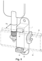
- the snap-fastening means make it possible to fix the support device 1 on a DIN rail 26.
- the second face 4 of the main body 2 of the support device 1 is brought against a first face 27 of the DIN rail 26, the hook 18 is positioned on the side of the second face 28 of the DIN rail 26, then the flexible tab 19 is snapped in such a way that the hook 23 of the flexible tab 19 is positioned against the second face 28 of the DIN rail 26.
- ribs 30 are formed inside the main body 2. These ribs 30 form a guide ramp 31 which rises from the second end 13 of the first face 3 to a base 32 of the flexible tab 19.
- the guide ramp 31 makes it easier to disassemble the support device 1 when the latter is fixed to the DIN rail 26 via the snap-fastening means.
- An operator can bring any elongated tool, for example a screwdriver 33, inside the main body 2 via the opening made in the first face 3.
- the guide ramp 31 guides the screwdriver 33 towards the flexible tab 19, so that the operator can press on the flexible tab 19 and thus easily release the snap-fastening means to disassemble the support device 1 from the DIN rail 26.
- the second device fixing means also comprises a support device 34 formed by a strip which extends along the edges of the second end 24 of the second face 4 of the main body 2 and which projects from the second face 4, perpendicular thereto, extending the walls of the third face 5, of the fourth face 6 and a fifth face 35 of the main body 2 of the support device 1.
- the support device 34 When the support device 1 is fixed to the DIN rail 26, the support device 34 comes to bear against the lower edge 36 of the DIN rail 26.
- the support device 34 makes it possible to prevent the rotation of the support device 1 relative to the DIN rail 26, but also to protect the flexible tab 19 from impacts, and to limit the travel of the flexible tab 19 to avoid deforming it beyond its elastic limit.
- the opening of the main body 2 by the first face 3, which allows access to the flexible tab 19 via this first face 3, also allows, at the time of manufacture by molding of the support device 1, to more easily demold the hook 18 and the flexible tab 19. This simplifies the manufacture of the support device 1.
- the plurality of device attachment means further comprises a third device attachment means which extends on or from the third face 5 of the main body 2 of the support device 1.
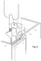
- the third device fixing means comprises an insert 40 intended to be introduced into a pre-existing notch 41 of a box 42, which is here a street cabinet box in which a data concentrator 43 is integrated.
- the box 42 is visible in the figures 7 And 8 .
- the insert 40 here extends over the third face 5 of the main body 2 of the support device 1.
- the insert 40 comprises a base 44 which extends over the third face 5, a plate 45 which extends over the base 44 while being wider than the base 44, and a rib 46 formed on the plate 45.
- the base 44, the plate 45 and the rib 46 are positioned successively from the third face 5 along an axis perpendicular to the third face 5.
- the base 44, the plate 45 and the rib 46 all have the shape of a horseshoe and each comprise a semi-circular portion and two linear branches.
- the free ends of the linear branches are located at an edge of the third face 5, in the extension of the first face 3 of the main body 2, while the semi-circular portions are oriented towards the inside of the third face 5. It is noted that the semi-circular portions cannot protrude from the third face 5, because otherwise they would prevent the mounting of the support device 1 on the DIN rail 26.
- the pre-existing notch 41 of the box 42 is made in a side wall 48 of the box 42.
- This side wall 48 comprises, according to its height, a first portion 49 which extends from a bottom of the box 42, then a second portion 50 which extends from the top of the first portion 49 to the upper edge of the side wall 48.
- the second portion 50 is slightly offset relative to the first portion 49, which forms a recess 51 facing the interior of the box 42, said recess 51 having the shape of a strip which runs along all the walls of the box 42 parallel to the upper edges of said walls.
- the pre-existing notch 41 is formed in the first portion 49 of the side wall 48 and opens into the recess 51.
- the pre-existing notch 41 comprises a first cavity 53 and a second cavity 54 which extend successively in the thickness of the first portion 49 of the side wall 48.
- the first cavity 53 has a shape complementary to the shape of the plate 45 of the insert 40 of the third device fixing means
- the second cavity 54 has a shape complementary to the shape of the rib 46 of the insert 40.
- the insert 40 can therefore be inserted into the pre-existing notch 41 in a direction Dir parallel to the side wall 48, the semi-circular portions of the base 44, the plate 45 and the rib 46 of the insert 40 penetrating first into the pre-existing notch 41.
- the plate 45 and the rib 46 extend respectively into the first cavity 53 and into the second cavity 54 of the pre-existing notch 41, and a portion of the thickness of the side wall 48 of the box 42 extends between the third face 5 of the main body 2 and the plate 45.
- the free ends of the linear branches of the base 44, of the plate 45 and of the rib 46 of the insert 40 are flush with the bottom 52 of the recess 51 corresponding to the limit between the first portion 49 and the second portion 50 of the side wall 48.
- the support device 1 When the insert 40 is positioned in the pre-existing notch 41, the support device 1 is held in position in the box 42.
- the only movement that the receiving device 1 can undergo is a movement in the opposite direction to the direction of movement in the direction Dir which made it possible to introduce the insert 40 into the pre-existing notch 41.
- the box 42 includes a cover 55 (or a door) for closing the box 42.
- the cover 55 is positioned against the box 42, so that the walls of the cover 55 come to rest on the bottom 52 of the recess 51.
- the cover 55 comes to press against the rib 46 of the insert 40 (positioned in the pre-existing notch 41) of the support device 1, and thus keeps the support device 1 completely immobile in the box 42 (see figure 8 ).
- the flat surface of the first face 3 of course allows, on the one hand, to fix the support device 1 against a wall (as was explained earlier), but also to increase the stability of the support device 1 when it is installed in the groove of a box.
- the flat surface of the third face 5 prevents the support device 1 from moving when the cover 55 of the box is in place.
- each box 42a, 42b thus has a side wall 48 fixed to a side wall 48 of the other box 42a, 42b.
- the pre-existing notches 41 of the side walls 48 of the boxes 42a, 42b are pierced.
- each screw 56 is positioned in a pre-existing notch 41 of the first box 41a, said screw 56 cooperating with a nut 57 positioned in a pre-existing notch 41 of the second box 42b.
- the third support fixing means is particularly clever, since it allows the support device 1 to be fixed to a pre-existing notch 41, originally intended for a completely different use.
- fixing means to the three device fixing means just described.
- a double-sided adhesive or an adhesive and a Velcro, or glue on the first face 3, on the tabs 10 and 11, (or on the gusset 63 which will be described below), etc.
- the support device 1 further comprises an equipment attachment means arranged to attach communication equipment to the support device 1.
- the equipment attachment means comprises a tab 60 which extends perpendicularly from the fourth face 6 of the main body 2.
- the fourth face 6 is opposite the third face 5 and is perpendicular to the first face 3 and the second face 4.
- the tab 60 includes a support hole 61 into which a connector of the communication equipment can be inserted.
- a flat 62 is provided in the support hole 61.
- a triangular reinforcement gusset 63 extends on either side of the tab 60, parallel to the first face 3 and in continuity with the first face 3.
- the reinforcing gusset 63 of course makes it possible to reinforce the tab 60 which can thus support relatively heavy communication equipment.
- the reinforcing gusset 63 also increases the surface area of the first face 3 and therefore the stability and robustness of the fixing of the support device 1 when it is mounted against a wall and fixed using the first device fixing means.
- the communication equipment here is an antenna 70.
- the antenna 70 is connected to a cable 71 via a connector which is in this case an SMA base 72.
- the SMA base 72 is inserted into the support hole 61 and is fixed to the tab 60.
- the flat 62 makes it possible to block the SMA base 72 in rotation.
- this equipment support means makes it possible to position the antenna 70 in two positions at 180° from each other.
- the antenna 70 can be oriented upwards, as is the case on the figure 4 , or downwards. This possibility is particularly practical and facilitates the integration of the 70 antenna into its operational environment.
- the support device 1 therefore comprises a plurality of device fixing means, which make it possible to fix the support device 1 and therefore the antenna 70 on different pre-existing reception devices: wall, DIN rail 26, notch 41 of the box 42, etc.
- the support device 1 can therefore be fixed to multiple pre-existing reception devices without modifying these pre-existing reception devices: the cost of the installation and its complexity are reduced. This is particularly advantageous in our application (and in many other applications).
- the data concentrator 43 incorporates its own antenna. However, if the communications implemented by the data concentrator 43 are poor, it may be necessary to increase the signal strength by using an additional antenna, i.e., the antenna 70. It is possible very easily integrate the antenna 70 into the box 42 containing the data concentrator 43, thanks to the support device 1, without modifying the box 42, using one of the four pre-existing notches 41 of the box 42.
- the box 42 is located in a very unfavorable location for radiofrequency communications, for example at the bottom of a cellar of a building.
- the antenna 70 can then be connected to the data concentrator 43 but moved outside the box 42, in a more favorable location.
- the support device 1 then makes it possible to fix the antenna 70 on another pre-existing reception device, such as a wall or a DIN rail.
- the antenna 70 When the support device 1 is fixed to a pre-existing host device by one of the device fixing means, the antenna 70 is in a predetermined position relative to the pre-existing host device and is at least a predefined minimum distance away from the pre-existing host device.
- the antenna 70 is at a minimum distance from the walls of the cabinet 42.
- the antenna is also at a minimum distance from the equipment of the cabinet 42 (in particular the data concentrator 43) and from all the surfaces inside the cabinet 42, which are likely to disturb the radio frequency communications, because the position of the antenna 70 is precisely defined by means of the support device 1.
- the antenna 70 when the antenna 70 is mounted on the DIN rail 26 or on a wall using the support device 1, it is at least a predefined minimum distance Dm from the DIN rail and the wall (see figures 4 And 5 ).
- the support device 1 comprises a plurality of device fixing means, it is no longer necessary to deliver to customers a kit of several support devices each adapted to a pre-existing reception device capable of accommodating the antenna 70. This reduces the cost of the complete solution delivered to customers.
- the support device 1 also makes it possible to deliver to customers a “turnkey” solution comprising the antenna 70, the SMA base 72 and the cable 71, all of these elements being assembled.
- the installation of the antenna 70 is therefore made easier for the customer and can be done more quickly.
- the support device 1 also makes it possible to limit the risk of degradation of radiofrequency performance resulting from incorrect installation, for example from a tightening torque of the antenna 70 or the SMA base 72 not being respected.
- the communication system comprising the antenna 70, the cable 71, the SMA socket 72 and the support device 1 can be assembled and then tested in the factory before the system is delivered. Since the customer does not need to disassemble this system, even if he changes its place, the radio performance tested and guaranteed in the factory cannot be degraded following the installation carried out by the customer. The risk of loss of radio performance due to improper assembly by the customer is eliminated by this invention.
- the communication equipment is not necessarily an antenna, but can be any type of equipment that can be used to communicate, for example an optical fiber.
- the antenna fixed to the support device, is connected to a data concentrator.
- the support device can however be integrated into any type of electrical equipment (electricity meter, industrial equipment, telecommunications equipment, radio base station of an information system, etc.), and carry communication equipment connected to any type of electrical equipment.
Landscapes
- Engineering & Computer Science (AREA)
- General Engineering & Computer Science (AREA)
- Mechanical Engineering (AREA)
- Casings For Electric Apparatus (AREA)
- Structure Of Receivers (AREA)
- Transceivers (AREA)
Claims (16)
- Halterungsvorrichtung eines Kommunikationsgeräts (70), welche ein Gerätebefestigungsmittel (60) enthält, das dazu angeordnet ist, das Kommunikationsgerät an der Halterungsvorrichtung (1) zu befestigen, wobei die Vorrichtung dadurch gekennzeichnet ist, dass sie eine Mehrzahl von Vorrichtungsbefestigungsmitteln (10, 11, 14, 18, 19, 40) umfasst, die jeweils dazu angeordnet sind, die Halterungsvorrichtung (1) an einer separaten, bereits vorhandenen Aufnahmevorrichtung (26) zu befestigen, wobei das Gerätebefestigungsmittel und die Vorrichtungsbefestigungsmittel derart angeordnet sind, dass, wenn das Kommunikationsgerät dank dem Gerätebefestigungsmittel an der Halterungsvorrichtung (1) befestigt ist und die Halterungsvorrichtung (1) dank einem der Vorrichtungsbefestigungsmittel an einer bereits vorhandenen Aufnahmevorrichtung befestigt ist, das Kommunikationsgerät (70) um zumindest eine vorbestimmte Mindestdistanz (Dm) von der bereits vorhandenen Aufnahmevorrichtung beabstandet ist.
- Halterungsvorrichtung nach Anspruch 1, wobei es sich bei dem Kommunikationsgerät um eine Antenne (70) handelt.
- Halterungsvorrichtung nach einem der vorhergehenden Ansprüche, welche einen im Allgemeinen quaderförmigen Hauptkörper (2) enthält, der eine erste Fläche (3) und eine der ersten Fläche (3) gegenüberliegende zweite Fläche (4) umfasst, wobei die Halterungsvorrichtung (1) enthält: ein erstes Vorrichtungsbefestigungsmittel, das sich über die erste Fläche (3) bzw. von dieser weg erstreckt und das dazu angeordnet ist, die Halterungsvorrichtung an einer Wand zu befestigen, wenn die erste Fläche gegen die Wand positioniert ist, und ein zweites Vorrichtungsbefestigungsmittel, das sich über die zweite Fläche (4) oder von dieser weg erstreckt.
- Halterungsvorrichtung nach Anspruch 3, wobei das erste Vorrichtungsbefestigungsmittel zwei Flansche (10, 11) enthält, die sich jeweils von einem unterschiedlichen Ende der ersten Fläche des Hauptkörpers (2) weg erstrecken wobei in jedem Flansch eine Befestigungsbohrung (14) angebracht ist.
- Halterungsvorrichtung nach Anspruch 3, wobei das zweite Vorrichtungsbefestigungsmittel Einrastmittel (18, 19) enthält, die dazu angeordnet sind, die Halterungsvorrichtung an einer DIN-Schiene (26) zu befestigen.
- Halterungsvorrichtung nach Anspruch 3, welche ferner ein drittes Vorrichtungsbefestigungsmittel enthält, das einen Einsatz (40) umfasst, der sich über eine dritte Fläche (5) des Hauptkörpers (2) bzw. von dieser weg erstreckt, wobei die dritte Fläche senkrecht zu der ersten Fläche (3) und zu der zweiten Fläche (4) verläuft, wobei der Einsatz dazu angeordnet ist, in eine bereits vorhandene Einkerbung (41) einer Wand (48) eines Gehäuses (42) eingesetzt zu werden.
- Halterungsvorrichtung nach Anspruch 6, wobei der Einsatz (40) eine sich über die dritte Fläche erstreckende Basis (44), eine auf der Basis (44) positionierte und breiter ist als die Basis ausgebildete Platte (45) und eine an der Platte (45) angeformte Rippe (46) enthält, wobei der Einsatz (40) derart angeordnet ist, dass, wenn die Halterungsvorrichtung (1) durch das dritte Vorrichtungsbefestigungsmittel an dem Gehäuse (42) befestigt ist, die Platte und die Rippe sich jeweils in einen ersten Hohlraum (53) und in einen zweiten Hohlraum (54) der bereits vorhandenen Einkerbung (41) hinein erstrecken, und ein Abschnitt der Wanddicke des Gehäuses (42) sich zwischen der dritten Fläche (5) des Hauptkörpers und der Platte (45) erstreckt.
- Halterungsvorrichtung nach Anspruch 3, wobei das Gerätebefestigungsmittel eine Lasche (60) enthält, die sich senkrecht von einer vierten Fläche (6) des Hauptkörpers (2) erstreckt, wobei die vierte Fläche senkrecht zu der ersten Fläche (3) und zu der zweiten Fläche (4) verläuft, wobei die Lasche (60) eine Trägerbohrung (61) umfasst, in welche ein an das Kommunikationsgerät (70) angeschlossener Verbinder (72) eingesetzt werden kann.
- Halterungsvorrichtung nach Anspruch 8, wobei in der Trägerbohrung (61) ein Steg (62) ausgebildet ist, wobei der Steg dazu angeordnet ist, den Verbinder verdrehgesichert zu blockieren.
- Kommunikationssystem, welches eine Halterungsvorrichtung (1) nach einem der vorhergehenden Ansprüche und ein von der Halterungsvorrichtung in Position gehaltenes Kommunikationsgerät (70) umfasst.
- Kommunikationssystem nach dem Anspruch 10, welches eine Halterungsvorrichtung nach Anspruch 8 umfasst, wobei es sich bei dem Kommunikationsgerät um eine Antenne (70) handelt, wobei das Kommunikationssystem ferner ein Kabel (71) und einen Verbinder (72) umfasst, wobei die Antenne (70) durch den Verbinder (72) an das Kabel (71) angeschlossen ist, wobei der Verbinder in die Trägerbohrung (61) der Lasche (60) eingesetzt und an der Lasche (60) befestigt ist.
- Kommunikationssystem nach Anspruch 11, wobei sich die Antenne (70) in ihrer Längserstreckung parallel zu der vierten Fläche (6) des Hauptkörpers (2) erstreckt.
- Elektrisches Gerät, welches ein Kommunikationssystem nach einem der Ansprüche 11 oder 12 umfasst.
- Elektrisches Gerät nach Anspruch 13, wobei das elektrische Gerät ein Schrankgehäuse (42) umfasst, in welchem ein Datenkonzentrator (43) integriert ist, der dazu angeordnet ist, mit einem Stromzähler zu kommunizieren.
- Elektrisches Gerät nach Anspruch 13, wobei es sich bei dem elektrischen Gerät um einen Stromzähler handelt.
- Verfahren zur Installation eines Kommunikationsgeräts an einer bereits vorhandenen Aufnahmevorrichtung, welches die Schritte umfasst, dass:- das Kommunikationsgerät unter Verwendung des Gerätebefestigungsmittels der Halterungsvorrichtung an der Halterungsvorrichtung nach einem der Ansprüche 1 bis 9 befestigt wird;- die Halterungsvorrichtung unter Verwendung von einem der Vorrichtungsbefestigungsmittel der Halterungsvorrichtung an der bereits vorhandenen Aufnahmevorrichtung befestigt wird.
Applications Claiming Priority (1)
| Application Number | Priority Date | Filing Date | Title |
|---|---|---|---|
| FR1872695A FR3089741B1 (fr) | 2018-12-10 | 2018-12-10 | Dispositif de support d’un équipement de communication, comprenant une pluralité de moyens de fixation |
Publications (2)
| Publication Number | Publication Date |
|---|---|
| EP3667149A1 EP3667149A1 (de) | 2020-06-17 |
| EP3667149B1 true EP3667149B1 (de) | 2024-09-11 |
Family
ID=66530198
Family Applications (1)
| Application Number | Title | Priority Date | Filing Date |
|---|---|---|---|
| EP19210801.7A Active EP3667149B1 (de) | 2018-12-10 | 2019-11-21 | Halterungsvorrichtung eines kommunikationsgeräts, das eine vielzahl von befestigungsmitteln umfasst |
Country Status (2)
| Country | Link |
|---|---|
| EP (1) | EP3667149B1 (de) |
| FR (1) | FR3089741B1 (de) |
Family Cites Families (2)
| Publication number | Priority date | Publication date | Assignee | Title |
|---|---|---|---|---|
| CN103277649A (zh) * | 2013-05-23 | 2013-09-04 | 裴旭波 | 棘轮调节电视机架 |
| CN205618940U (zh) * | 2016-04-22 | 2016-10-05 | 宁波欧格电子有限公司 | 一种改进型电视挂架 |
-
2018
- 2018-12-10 FR FR1872695A patent/FR3089741B1/fr active Active
-
2019
- 2019-11-21 EP EP19210801.7A patent/EP3667149B1/de active Active
Also Published As
| Publication number | Publication date |
|---|---|
| EP3667149A1 (de) | 2020-06-17 |
| FR3089741B1 (fr) | 2023-07-14 |
| FR3089741A1 (fr) | 2020-06-12 |
Similar Documents
| Publication | Publication Date | Title |
|---|---|---|
| FR3000310A1 (fr) | Module d'appareillage electrique | |
| FR3000312A1 (fr) | Boite electrique pour appareillage electrique | |
| FR3020514A1 (fr) | Appareillage electrique a assemblage securise | |
| EP2312700A1 (de) | Teil eines elektrischen Verbinders und damit electrischer Verbinder. | |
| EP2859631B1 (de) | Endmaskenplatte mit zentrierungsmitteln für ein innenelement von einem elektrischen apparat | |
| EP3667149B1 (de) | Halterungsvorrichtung eines kommunikationsgeräts, das eine vielzahl von befestigungsmitteln umfasst | |
| EP1149447A1 (de) | Gerätegehalter ,insbesondere für elektrisches gerät und damit ausgerüstetes gehäuse | |
| FR3113088A1 (fr) | Structure de volet roulant et méthode de montage | |
| FR2957727A1 (fr) | Support de rail de montage d'appareillages electriques dans un coffret electrique | |
| FR3076104A1 (fr) | Support d'appareillage electrique recevant un element de montage | |
| EP3952624B1 (de) | Modulare elektronische anordnung und mobiles videosystem mit einer solchen anordnung | |
| EP2112734B1 (de) | Elektrogerät zum Aufsetzen auf ein Einbaugehäuse | |
| FR2926408A1 (fr) | Accessoire pour goulotte electrique, ensemble electrique comprenant un appareillage electrique et un tel accessoire et ensemble electrique comprenant une goulotte electrique et un tel accessoire | |
| EP2958195B1 (de) | Modul-vorrichtung für kommunikationsbox | |
| FR2924535A1 (fr) | Appareillage electrique encastre a connexion rapide | |
| EP1744426B1 (de) | Elektrischer Kasten bestehend aus zwei Elemente die mit einer Zahnstange zusammen befestigt sind | |
| EP2320532B1 (de) | Vorrichtung zur Montage eines Pfostens am hinteren Teil eines Stromverteilungskastens, und mit einer solchen Vorrichtung ausgestatteter Stromverteilungskasten | |
| FR3058502A1 (fr) | Dispositif de montage sans vis d'un boitier de commande de projecteur sur ledit projecteur | |
| WO2014118445A1 (fr) | Boite d'encastrement en deux parties | |
| FR2549168A1 (fr) | Systeme d'assemblage d'elements constitutifs identiques ou similaires de boitiers d'appareillage et elements constitutifs dotes d'un tel systeme | |
| FR2959381A1 (fr) | Coffret ou tableau de distribution electrique muni de moyens de fixation automatique du capot sur le chassis | |
| EP2422416B1 (de) | Höheneinstellbare bodendose | |
| EP1343238B1 (de) | Dose für elektrisches Gerät mit biegsamer Befestigung | |
| FR3153102A1 (fr) | Dispositif de fixation d’un grillage sur un montant de clôture | |
| EP1403992B1 (de) | Lokalisierungszubehör für ein Profilelement in einer Wand und damit ausgerüstetes Profilelement |
Legal Events
| Date | Code | Title | Description |
|---|---|---|---|
| PUAI | Public reference made under article 153(3) epc to a published international application that has entered the european phase |
Free format text: ORIGINAL CODE: 0009012 |
|
| STAA | Information on the status of an ep patent application or granted ep patent |
Free format text: STATUS: THE APPLICATION HAS BEEN PUBLISHED |
|
| AK | Designated contracting states |
Kind code of ref document: A1 Designated state(s): AL AT BE BG CH CY CZ DE DK EE ES FI FR GB GR HR HU IE IS IT LI LT LU LV MC MK MT NL NO PL PT RO RS SE SI SK SM TR |
|
| AX | Request for extension of the european patent |
Extension state: BA ME |
|
| STAA | Information on the status of an ep patent application or granted ep patent |
Free format text: STATUS: REQUEST FOR EXAMINATION WAS MADE |
|
| 17P | Request for examination filed |
Effective date: 20201127 |
|
| RBV | Designated contracting states (corrected) |
Designated state(s): AL AT BE BG CH CY CZ DE DK EE ES FI FR GB GR HR HU IE IS IT LI LT LU LV MC MK MT NL NO PL PT RO RS SE SI SK SM TR |
|
| STAA | Information on the status of an ep patent application or granted ep patent |
Free format text: STATUS: EXAMINATION IS IN PROGRESS |
|
| 17Q | First examination report despatched |
Effective date: 20210827 |
|
| RAP3 | Party data changed (applicant data changed or rights of an application transferred) |
Owner name: SAGEMCOM ENERGY & TELECOM SAS |
|
| GRAP | Despatch of communication of intention to grant a patent |
Free format text: ORIGINAL CODE: EPIDOSNIGR1 |
|
| STAA | Information on the status of an ep patent application or granted ep patent |
Free format text: STATUS: GRANT OF PATENT IS INTENDED |
|
| INTG | Intention to grant announced |
Effective date: 20240412 |
|
| GRAS | Grant fee paid |
Free format text: ORIGINAL CODE: EPIDOSNIGR3 |
|
| GRAA | (expected) grant |
Free format text: ORIGINAL CODE: 0009210 |
|
| STAA | Information on the status of an ep patent application or granted ep patent |
Free format text: STATUS: THE PATENT HAS BEEN GRANTED |
|
| AK | Designated contracting states |
Kind code of ref document: B1 Designated state(s): AL AT BE BG CH CY CZ DE DK EE ES FI FR GB GR HR HU IE IS IT LI LT LU LV MC MK MT NL NO PL PT RO RS SE SI SK SM TR |
|
| REG | Reference to a national code |
Ref country code: GB Ref legal event code: FG4D Free format text: NOT ENGLISH |
|
| REG | Reference to a national code |
Ref country code: CH Ref legal event code: EP |
|
| REG | Reference to a national code |
Ref country code: DE Ref legal event code: R096 Ref document number: 602019058622 Country of ref document: DE |
|
| REG | Reference to a national code |
Ref country code: IE Ref legal event code: FG4D Free format text: LANGUAGE OF EP DOCUMENT: FRENCH |
|
| REG | Reference to a national code |
Ref country code: LT Ref legal event code: MG9D |
|
| PG25 | Lapsed in a contracting state [announced via postgrant information from national office to epo] |
Ref country code: NO Free format text: LAPSE BECAUSE OF FAILURE TO SUBMIT A TRANSLATION OF THE DESCRIPTION OR TO PAY THE FEE WITHIN THE PRESCRIBED TIME-LIMIT Effective date: 20241211 |
|
| REG | Reference to a national code |
Ref country code: NL Ref legal event code: MP Effective date: 20240911 |
|
| PG25 | Lapsed in a contracting state [announced via postgrant information from national office to epo] |
Ref country code: GR Free format text: LAPSE BECAUSE OF FAILURE TO SUBMIT A TRANSLATION OF THE DESCRIPTION OR TO PAY THE FEE WITHIN THE PRESCRIBED TIME-LIMIT Effective date: 20241212 Ref country code: FI Free format text: LAPSE BECAUSE OF FAILURE TO SUBMIT A TRANSLATION OF THE DESCRIPTION OR TO PAY THE FEE WITHIN THE PRESCRIBED TIME-LIMIT Effective date: 20240911 |
|
| PG25 | Lapsed in a contracting state [announced via postgrant information from national office to epo] |
Ref country code: BG Free format text: LAPSE BECAUSE OF FAILURE TO SUBMIT A TRANSLATION OF THE DESCRIPTION OR TO PAY THE FEE WITHIN THE PRESCRIBED TIME-LIMIT Effective date: 20240911 |
|
| PG25 | Lapsed in a contracting state [announced via postgrant information from national office to epo] |
Ref country code: LV Free format text: LAPSE BECAUSE OF FAILURE TO SUBMIT A TRANSLATION OF THE DESCRIPTION OR TO PAY THE FEE WITHIN THE PRESCRIBED TIME-LIMIT Effective date: 20240911 |
|
| PG25 | Lapsed in a contracting state [announced via postgrant information from national office to epo] |
Ref country code: HR Free format text: LAPSE BECAUSE OF FAILURE TO SUBMIT A TRANSLATION OF THE DESCRIPTION OR TO PAY THE FEE WITHIN THE PRESCRIBED TIME-LIMIT Effective date: 20240911 |
|
| PG25 | Lapsed in a contracting state [announced via postgrant information from national office to epo] |
Ref country code: RS Free format text: LAPSE BECAUSE OF FAILURE TO SUBMIT A TRANSLATION OF THE DESCRIPTION OR TO PAY THE FEE WITHIN THE PRESCRIBED TIME-LIMIT Effective date: 20241211 Ref country code: ES Free format text: LAPSE BECAUSE OF FAILURE TO SUBMIT A TRANSLATION OF THE DESCRIPTION OR TO PAY THE FEE WITHIN THE PRESCRIBED TIME-LIMIT Effective date: 20240911 |
|
| PG25 | Lapsed in a contracting state [announced via postgrant information from national office to epo] |
Ref country code: RS Free format text: LAPSE BECAUSE OF FAILURE TO SUBMIT A TRANSLATION OF THE DESCRIPTION OR TO PAY THE FEE WITHIN THE PRESCRIBED TIME-LIMIT Effective date: 20241211 Ref country code: NO Free format text: LAPSE BECAUSE OF FAILURE TO SUBMIT A TRANSLATION OF THE DESCRIPTION OR TO PAY THE FEE WITHIN THE PRESCRIBED TIME-LIMIT Effective date: 20241211 Ref country code: LV Free format text: LAPSE BECAUSE OF FAILURE TO SUBMIT A TRANSLATION OF THE DESCRIPTION OR TO PAY THE FEE WITHIN THE PRESCRIBED TIME-LIMIT Effective date: 20240911 Ref country code: HR Free format text: LAPSE BECAUSE OF FAILURE TO SUBMIT A TRANSLATION OF THE DESCRIPTION OR TO PAY THE FEE WITHIN THE PRESCRIBED TIME-LIMIT Effective date: 20240911 Ref country code: GR Free format text: LAPSE BECAUSE OF FAILURE TO SUBMIT A TRANSLATION OF THE DESCRIPTION OR TO PAY THE FEE WITHIN THE PRESCRIBED TIME-LIMIT Effective date: 20241212 Ref country code: FI Free format text: LAPSE BECAUSE OF FAILURE TO SUBMIT A TRANSLATION OF THE DESCRIPTION OR TO PAY THE FEE WITHIN THE PRESCRIBED TIME-LIMIT Effective date: 20240911 Ref country code: ES Free format text: LAPSE BECAUSE OF FAILURE TO SUBMIT A TRANSLATION OF THE DESCRIPTION OR TO PAY THE FEE WITHIN THE PRESCRIBED TIME-LIMIT Effective date: 20240911 Ref country code: BG Free format text: LAPSE BECAUSE OF FAILURE TO SUBMIT A TRANSLATION OF THE DESCRIPTION OR TO PAY THE FEE WITHIN THE PRESCRIBED TIME-LIMIT Effective date: 20240911 |
|
| REG | Reference to a national code |
Ref country code: AT Ref legal event code: MK05 Ref document number: 1722977 Country of ref document: AT Kind code of ref document: T Effective date: 20240911 |
|
| PG25 | Lapsed in a contracting state [announced via postgrant information from national office to epo] |
Ref country code: NL Free format text: LAPSE BECAUSE OF FAILURE TO SUBMIT A TRANSLATION OF THE DESCRIPTION OR TO PAY THE FEE WITHIN THE PRESCRIBED TIME-LIMIT Effective date: 20240911 |
|
| PG25 | Lapsed in a contracting state [announced via postgrant information from national office to epo] |
Ref country code: PT Free format text: LAPSE BECAUSE OF FAILURE TO SUBMIT A TRANSLATION OF THE DESCRIPTION OR TO PAY THE FEE WITHIN THE PRESCRIBED TIME-LIMIT Effective date: 20250113 Ref country code: IS Free format text: LAPSE BECAUSE OF FAILURE TO SUBMIT A TRANSLATION OF THE DESCRIPTION OR TO PAY THE FEE WITHIN THE PRESCRIBED TIME-LIMIT Effective date: 20250111 |
|
| PG25 | Lapsed in a contracting state [announced via postgrant information from national office to epo] |
Ref country code: RO Free format text: LAPSE BECAUSE OF FAILURE TO SUBMIT A TRANSLATION OF THE DESCRIPTION OR TO PAY THE FEE WITHIN THE PRESCRIBED TIME-LIMIT Effective date: 20240911 Ref country code: SM Free format text: LAPSE BECAUSE OF FAILURE TO SUBMIT A TRANSLATION OF THE DESCRIPTION OR TO PAY THE FEE WITHIN THE PRESCRIBED TIME-LIMIT Effective date: 20240911 |
|
| PG25 | Lapsed in a contracting state [announced via postgrant information from national office to epo] |
Ref country code: EE Free format text: LAPSE BECAUSE OF FAILURE TO SUBMIT A TRANSLATION OF THE DESCRIPTION OR TO PAY THE FEE WITHIN THE PRESCRIBED TIME-LIMIT Effective date: 20240911 Ref country code: AT Free format text: LAPSE BECAUSE OF FAILURE TO SUBMIT A TRANSLATION OF THE DESCRIPTION OR TO PAY THE FEE WITHIN THE PRESCRIBED TIME-LIMIT Effective date: 20240911 |
|
| PG25 | Lapsed in a contracting state [announced via postgrant information from national office to epo] |
Ref country code: CZ Free format text: LAPSE BECAUSE OF FAILURE TO SUBMIT A TRANSLATION OF THE DESCRIPTION OR TO PAY THE FEE WITHIN THE PRESCRIBED TIME-LIMIT Effective date: 20240911 Ref country code: PL Free format text: LAPSE BECAUSE OF FAILURE TO SUBMIT A TRANSLATION OF THE DESCRIPTION OR TO PAY THE FEE WITHIN THE PRESCRIBED TIME-LIMIT Effective date: 20240911 |
|
| PG25 | Lapsed in a contracting state [announced via postgrant information from national office to epo] |
Ref country code: SK Free format text: LAPSE BECAUSE OF FAILURE TO SUBMIT A TRANSLATION OF THE DESCRIPTION OR TO PAY THE FEE WITHIN THE PRESCRIBED TIME-LIMIT Effective date: 20240911 Ref country code: IT Free format text: LAPSE BECAUSE OF FAILURE TO SUBMIT A TRANSLATION OF THE DESCRIPTION OR TO PAY THE FEE WITHIN THE PRESCRIBED TIME-LIMIT Effective date: 20240911 |
|
| REG | Reference to a national code |
Ref country code: DE Ref legal event code: R097 Ref document number: 602019058622 Country of ref document: DE |
|
| REG | Reference to a national code |
Ref country code: CH Ref legal event code: PL |
|
| PG25 | Lapsed in a contracting state [announced via postgrant information from national office to epo] |
Ref country code: MC Free format text: LAPSE BECAUSE OF FAILURE TO SUBMIT A TRANSLATION OF THE DESCRIPTION OR TO PAY THE FEE WITHIN THE PRESCRIBED TIME-LIMIT Effective date: 20240911 |
|
| PG25 | Lapsed in a contracting state [announced via postgrant information from national office to epo] |
Ref country code: DK Free format text: LAPSE BECAUSE OF FAILURE TO SUBMIT A TRANSLATION OF THE DESCRIPTION OR TO PAY THE FEE WITHIN THE PRESCRIBED TIME-LIMIT Effective date: 20240911 |
|
| PG25 | Lapsed in a contracting state [announced via postgrant information from national office to epo] |
Ref country code: LU Free format text: LAPSE BECAUSE OF NON-PAYMENT OF DUE FEES Effective date: 20241121 |
|
| REG | Reference to a national code |
Ref country code: CH Ref legal event code: PL |
|
| PLBE | No opposition filed within time limit |
Free format text: ORIGINAL CODE: 0009261 |
|
| STAA | Information on the status of an ep patent application or granted ep patent |
Free format text: STATUS: NO OPPOSITION FILED WITHIN TIME LIMIT |
|
| PG25 | Lapsed in a contracting state [announced via postgrant information from national office to epo] |
Ref country code: CH Free format text: LAPSE BECAUSE OF NON-PAYMENT OF DUE FEES Effective date: 20241130 |
|
| 26N | No opposition filed |
Effective date: 20250612 |
|
| REG | Reference to a national code |
Ref country code: BE Ref legal event code: MM Effective date: 20241130 |
|
| PG25 | Lapsed in a contracting state [announced via postgrant information from national office to epo] |
Ref country code: SE Free format text: LAPSE BECAUSE OF FAILURE TO SUBMIT A TRANSLATION OF THE DESCRIPTION OR TO PAY THE FEE WITHIN THE PRESCRIBED TIME-LIMIT Effective date: 20240911 |
|
| PG25 | Lapsed in a contracting state [announced via postgrant information from national office to epo] |
Ref country code: BE Free format text: LAPSE BECAUSE OF NON-PAYMENT OF DUE FEES Effective date: 20241130 |
|
| PG25 | Lapsed in a contracting state [announced via postgrant information from national office to epo] |
Ref country code: IE Free format text: LAPSE BECAUSE OF NON-PAYMENT OF DUE FEES Effective date: 20241121 |
|
| PGFP | Annual fee paid to national office [announced via postgrant information from national office to epo] |
Ref country code: DE Payment date: 20251022 Year of fee payment: 7 |
|
| PGFP | Annual fee paid to national office [announced via postgrant information from national office to epo] |
Ref country code: GB Payment date: 20251023 Year of fee payment: 7 |
|
| PGFP | Annual fee paid to national office [announced via postgrant information from national office to epo] |
Ref country code: FR Payment date: 20251023 Year of fee payment: 7 |
|
| PG25 | Lapsed in a contracting state [announced via postgrant information from national office to epo] |
Ref country code: HU Free format text: LAPSE BECAUSE OF FAILURE TO SUBMIT A TRANSLATION OF THE DESCRIPTION OR TO PAY THE FEE WITHIN THE PRESCRIBED TIME-LIMIT; INVALID AB INITIO Effective date: 20191121 |
|
| PG25 | Lapsed in a contracting state [announced via postgrant information from national office to epo] |
Ref country code: CY Free format text: LAPSE BECAUSE OF FAILURE TO SUBMIT A TRANSLATION OF THE DESCRIPTION OR TO PAY THE FEE WITHIN THE PRESCRIBED TIME-LIMIT; INVALID AB INITIO Effective date: 20191121 |