EP3667087B1 - Pumpenanordnung - Google Patents
Pumpenanordnung Download PDFInfo
- Publication number
- EP3667087B1 EP3667087B1 EP18212317.4A EP18212317A EP3667087B1 EP 3667087 B1 EP3667087 B1 EP 3667087B1 EP 18212317 A EP18212317 A EP 18212317A EP 3667087 B1 EP3667087 B1 EP 3667087B1
- Authority
- EP
- European Patent Office
- Prior art keywords
- rotor
- radial
- pump
- housing
- pump housing
- Prior art date
- Legal status (The legal status is an assumption and is not a legal conclusion. Google has not performed a legal analysis and makes no representation as to the accuracy of the status listed.)
- Active
Links
- 239000000463 material Substances 0.000 claims description 104
- 238000004519 manufacturing process Methods 0.000 claims description 12
- 238000002347 injection Methods 0.000 claims description 9
- 239000007924 injection Substances 0.000 claims description 9
- 230000000052 comparative effect Effects 0.000 claims description 6
- 238000000034 method Methods 0.000 claims 2
- 239000012530 fluid Substances 0.000 description 16
- YTBRNEUEFCNVHC-UHFFFAOYSA-N 4,4'-dichlorobiphenyl Chemical compound C1=CC(Cl)=CC=C1C1=CC=C(Cl)C=C1 YTBRNEUEFCNVHC-UHFFFAOYSA-N 0.000 description 12
- 239000004020 conductor Substances 0.000 description 12
- 238000013461 design Methods 0.000 description 9
- 239000004952 Polyamide Substances 0.000 description 6
- 239000000919 ceramic Substances 0.000 description 6
- 230000017525 heat dissipation Effects 0.000 description 6
- 239000004033 plastic Substances 0.000 description 6
- 229920003023 plastic Polymers 0.000 description 6
- 229920002647 polyamide Polymers 0.000 description 6
- 238000005086 pumping Methods 0.000 description 6
- 238000004804 winding Methods 0.000 description 6
- OKTJSMMVPCPJKN-UHFFFAOYSA-N Carbon Chemical compound [C] OKTJSMMVPCPJKN-UHFFFAOYSA-N 0.000 description 4
- 239000004696 Poly ether ether ketone Substances 0.000 description 4
- 238000003754 machining Methods 0.000 description 4
- 229920002530 polyetherether ketone Polymers 0.000 description 4
- 239000002482 conductive additive Substances 0.000 description 3
- 238000009434 installation Methods 0.000 description 3
- 238000009413 insulation Methods 0.000 description 3
- 239000010410 layer Substances 0.000 description 3
- 239000002184 metal Substances 0.000 description 3
- 229910052751 metal Inorganic materials 0.000 description 3
- 238000012986 modification Methods 0.000 description 3
- 230000004048 modification Effects 0.000 description 3
- -1 polyphenylene Polymers 0.000 description 3
- 230000035939 shock Effects 0.000 description 3
- 229910052582 BN Inorganic materials 0.000 description 2
- PZNSFCLAULLKQX-UHFFFAOYSA-N Boron nitride Chemical compound N#B PZNSFCLAULLKQX-UHFFFAOYSA-N 0.000 description 2
- 229920000049 Carbon (fiber) Polymers 0.000 description 2
- XEEYBQQBJWHFJM-UHFFFAOYSA-N Iron Chemical compound [Fe] XEEYBQQBJWHFJM-UHFFFAOYSA-N 0.000 description 2
- 229920000106 Liquid crystal polymer Polymers 0.000 description 2
- 239000004977 Liquid-crystal polymers (LCPs) Substances 0.000 description 2
- 229920000265 Polyparaphenylene Polymers 0.000 description 2
- UCKMPCXJQFINFW-UHFFFAOYSA-N Sulphide Chemical compound [S-2] UCKMPCXJQFINFW-UHFFFAOYSA-N 0.000 description 2
- 230000009286 beneficial effect Effects 0.000 description 2
- 229910052799 carbon Inorganic materials 0.000 description 2
- 239000004917 carbon fiber Substances 0.000 description 2
- 239000011248 coating agent Substances 0.000 description 2
- 238000000576 coating method Methods 0.000 description 2
- 239000003365 glass fiber Substances 0.000 description 2
- 229910002804 graphite Inorganic materials 0.000 description 2
- 239000010439 graphite Substances 0.000 description 2
- 238000010438 heat treatment Methods 0.000 description 2
- 230000001050 lubricating effect Effects 0.000 description 2
- 238000003801 milling Methods 0.000 description 2
- 229920000139 polyethylene terephthalate Polymers 0.000 description 2
- 239000005020 polyethylene terephthalate Substances 0.000 description 2
- 238000012545 processing Methods 0.000 description 2
- 238000007789 sealing Methods 0.000 description 2
- 238000006467 substitution reaction Methods 0.000 description 2
- XLYOFNOQVPJJNP-UHFFFAOYSA-N water Substances O XLYOFNOQVPJJNP-UHFFFAOYSA-N 0.000 description 2
- 230000006978 adaptation Effects 0.000 description 1
- 230000000712 assembly Effects 0.000 description 1
- 238000000429 assembly Methods 0.000 description 1
- 239000011247 coating layer Substances 0.000 description 1
- 230000008602 contraction Effects 0.000 description 1
- 238000005336 cracking Methods 0.000 description 1
- 238000013016 damping Methods 0.000 description 1
- 230000003247 decreasing effect Effects 0.000 description 1
- 238000009826 distribution Methods 0.000 description 1
- 238000005553 drilling Methods 0.000 description 1
- 239000012777 electrically insulating material Substances 0.000 description 1
- 238000003780 insertion Methods 0.000 description 1
- 230000037431 insertion Effects 0.000 description 1
- 229910052742 iron Inorganic materials 0.000 description 1
- 239000000314 lubricant Substances 0.000 description 1
- 238000004382 potting Methods 0.000 description 1
- 230000002265 prevention Effects 0.000 description 1
- 239000011347 resin Substances 0.000 description 1
- 229920005989 resin Polymers 0.000 description 1
- 239000000243 solution Substances 0.000 description 1
- 239000000126 substance Substances 0.000 description 1
- 230000001360 synchronised effect Effects 0.000 description 1
- 238000012546 transfer Methods 0.000 description 1
- 229910000859 α-Fe Inorganic materials 0.000 description 1
Images


Classifications
-
- F—MECHANICAL ENGINEERING; LIGHTING; HEATING; WEAPONS; BLASTING
- F04—POSITIVE - DISPLACEMENT MACHINES FOR LIQUIDS; PUMPS FOR LIQUIDS OR ELASTIC FLUIDS
- F04D—NON-POSITIVE-DISPLACEMENT PUMPS
- F04D13/00—Pumping installations or systems
- F04D13/02—Units comprising pumps and their driving means
- F04D13/06—Units comprising pumps and their driving means the pump being electrically driven
- F04D13/0606—Canned motor pumps
-
- B—PERFORMING OPERATIONS; TRANSPORTING
- B29—WORKING OF PLASTICS; WORKING OF SUBSTANCES IN A PLASTIC STATE IN GENERAL
- B29C—SHAPING OR JOINING OF PLASTICS; SHAPING OF MATERIAL IN A PLASTIC STATE, NOT OTHERWISE PROVIDED FOR; AFTER-TREATMENT OF THE SHAPED PRODUCTS, e.g. REPAIRING
- B29C45/00—Injection moulding, i.e. forcing the required volume of moulding material through a nozzle into a closed mould; Apparatus therefor
- B29C45/16—Making multilayered or multicoloured articles
- B29C45/1615—The materials being injected at different moulding stations
-
- F—MECHANICAL ENGINEERING; LIGHTING; HEATING; WEAPONS; BLASTING
- F04—POSITIVE - DISPLACEMENT MACHINES FOR LIQUIDS; PUMPS FOR LIQUIDS OR ELASTIC FLUIDS
- F04D—NON-POSITIVE-DISPLACEMENT PUMPS
- F04D13/00—Pumping installations or systems
- F04D13/02—Units comprising pumps and their driving means
- F04D13/06—Units comprising pumps and their driving means the pump being electrically driven
- F04D13/0606—Canned motor pumps
- F04D13/0626—Details of the can
-
- F—MECHANICAL ENGINEERING; LIGHTING; HEATING; WEAPONS; BLASTING
- F04—POSITIVE - DISPLACEMENT MACHINES FOR LIQUIDS; PUMPS FOR LIQUIDS OR ELASTIC FLUIDS
- F04D—NON-POSITIVE-DISPLACEMENT PUMPS
- F04D13/00—Pumping installations or systems
- F04D13/02—Units comprising pumps and their driving means
- F04D13/06—Units comprising pumps and their driving means the pump being electrically driven
- F04D13/0606—Canned motor pumps
- F04D13/064—Details of the magnetic circuit
-
- F—MECHANICAL ENGINEERING; LIGHTING; HEATING; WEAPONS; BLASTING
- F04—POSITIVE - DISPLACEMENT MACHINES FOR LIQUIDS; PUMPS FOR LIQUIDS OR ELASTIC FLUIDS
- F04D—NON-POSITIVE-DISPLACEMENT PUMPS
- F04D13/00—Pumping installations or systems
- F04D13/02—Units comprising pumps and their driving means
- F04D13/06—Units comprising pumps and their driving means the pump being electrically driven
- F04D13/0686—Mechanical details of the pump control unit
-
- F—MECHANICAL ENGINEERING; LIGHTING; HEATING; WEAPONS; BLASTING
- F04—POSITIVE - DISPLACEMENT MACHINES FOR LIQUIDS; PUMPS FOR LIQUIDS OR ELASTIC FLUIDS
- F04D—NON-POSITIVE-DISPLACEMENT PUMPS
- F04D13/00—Pumping installations or systems
- F04D13/02—Units comprising pumps and their driving means
- F04D13/06—Units comprising pumps and their driving means the pump being electrically driven
- F04D13/0693—Details or arrangements of the wiring
-
- F—MECHANICAL ENGINEERING; LIGHTING; HEATING; WEAPONS; BLASTING
- F04—POSITIVE - DISPLACEMENT MACHINES FOR LIQUIDS; PUMPS FOR LIQUIDS OR ELASTIC FLUIDS
- F04D—NON-POSITIVE-DISPLACEMENT PUMPS
- F04D29/00—Details, component parts, or accessories
- F04D29/02—Selection of particular materials
- F04D29/026—Selection of particular materials especially adapted for liquid pumps
-
- F—MECHANICAL ENGINEERING; LIGHTING; HEATING; WEAPONS; BLASTING
- F04—POSITIVE - DISPLACEMENT MACHINES FOR LIQUIDS; PUMPS FOR LIQUIDS OR ELASTIC FLUIDS
- F04D—NON-POSITIVE-DISPLACEMENT PUMPS
- F04D29/00—Details, component parts, or accessories
- F04D29/04—Shafts or bearings, or assemblies thereof
- F04D29/043—Shafts
-
- F—MECHANICAL ENGINEERING; LIGHTING; HEATING; WEAPONS; BLASTING
- F04—POSITIVE - DISPLACEMENT MACHINES FOR LIQUIDS; PUMPS FOR LIQUIDS OR ELASTIC FLUIDS
- F04D—NON-POSITIVE-DISPLACEMENT PUMPS
- F04D29/00—Details, component parts, or accessories
- F04D29/04—Shafts or bearings, or assemblies thereof
- F04D29/046—Bearings
-
- F—MECHANICAL ENGINEERING; LIGHTING; HEATING; WEAPONS; BLASTING
- F04—POSITIVE - DISPLACEMENT MACHINES FOR LIQUIDS; PUMPS FOR LIQUIDS OR ELASTIC FLUIDS
- F04D—NON-POSITIVE-DISPLACEMENT PUMPS
- F04D29/00—Details, component parts, or accessories
- F04D29/40—Casings; Connections of working fluid
- F04D29/42—Casings; Connections of working fluid for radial or helico-centrifugal pumps
- F04D29/426—Casings; Connections of working fluid for radial or helico-centrifugal pumps especially adapted for liquid pumps
-
- F—MECHANICAL ENGINEERING; LIGHTING; HEATING; WEAPONS; BLASTING
- F04—POSITIVE - DISPLACEMENT MACHINES FOR LIQUIDS; PUMPS FOR LIQUIDS OR ELASTIC FLUIDS
- F04D—NON-POSITIVE-DISPLACEMENT PUMPS
- F04D29/00—Details, component parts, or accessories
- F04D29/58—Cooling; Heating; Diminishing heat transfer
- F04D29/5806—Cooling the drive system
-
- F—MECHANICAL ENGINEERING; LIGHTING; HEATING; WEAPONS; BLASTING
- F04—POSITIVE - DISPLACEMENT MACHINES FOR LIQUIDS; PUMPS FOR LIQUIDS OR ELASTIC FLUIDS
- F04D—NON-POSITIVE-DISPLACEMENT PUMPS
- F04D29/00—Details, component parts, or accessories
- F04D29/58—Cooling; Heating; Diminishing heat transfer
- F04D29/5813—Cooling the control unit
-
- F—MECHANICAL ENGINEERING; LIGHTING; HEATING; WEAPONS; BLASTING
- F04—POSITIVE - DISPLACEMENT MACHINES FOR LIQUIDS; PUMPS FOR LIQUIDS OR ELASTIC FLUIDS
- F04D—NON-POSITIVE-DISPLACEMENT PUMPS
- F04D29/00—Details, component parts, or accessories
- F04D29/58—Cooling; Heating; Diminishing heat transfer
- F04D29/586—Cooling; Heating; Diminishing heat transfer specially adapted for liquid pumps
- F04D29/5893—Cooling; Heating; Diminishing heat transfer specially adapted for liquid pumps heat insulation or conduction
-
- F—MECHANICAL ENGINEERING; LIGHTING; HEATING; WEAPONS; BLASTING
- F04—POSITIVE - DISPLACEMENT MACHINES FOR LIQUIDS; PUMPS FOR LIQUIDS OR ELASTIC FLUIDS
- F04D—NON-POSITIVE-DISPLACEMENT PUMPS
- F04D29/00—Details, component parts, or accessories
- F04D29/60—Mounting; Assembling; Disassembling
- F04D29/62—Mounting; Assembling; Disassembling of radial or helico-centrifugal pumps
- F04D29/628—Mounting; Assembling; Disassembling of radial or helico-centrifugal pumps especially adapted for liquid pumps
-
- H—ELECTRICITY
- H05—ELECTRIC TECHNIQUES NOT OTHERWISE PROVIDED FOR
- H05K—PRINTED CIRCUITS; CASINGS OR CONSTRUCTIONAL DETAILS OF ELECTRIC APPARATUS; MANUFACTURE OF ASSEMBLAGES OF ELECTRICAL COMPONENTS
- H05K5/00—Casings, cabinets or drawers for electric apparatus
- H05K5/02—Details
- H05K5/03—Covers
-
- H—ELECTRICITY
- H05—ELECTRIC TECHNIQUES NOT OTHERWISE PROVIDED FOR
- H05K—PRINTED CIRCUITS; CASINGS OR CONSTRUCTIONAL DETAILS OF ELECTRIC APPARATUS; MANUFACTURE OF ASSEMBLAGES OF ELECTRICAL COMPONENTS
- H05K7/00—Constructional details common to different types of electric apparatus
- H05K7/20—Modifications to facilitate cooling, ventilating, or heating
- H05K7/2039—Modifications to facilitate cooling, ventilating, or heating characterised by the heat transfer by conduction from the heat generating element to a dissipating body
Definitions
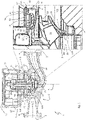
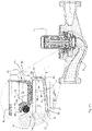
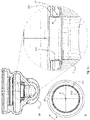
- Fig. 13 shows a situation during assembly of the pump assembly 1 before the rotor can 57 is secured in position by means of the locking ring 85.
- Fig. 14 shows a situation after the rotor can 57 is secured in position by means of the locking ring 85.
- the bearing retainer 41 is placed into the pump housing 11 to rest on the axial annular stop surface 39 of the pump housing 11.
- the rotor can 57 is then pressed downwards with its lower annular contact surface 89 onto the axial protrusions 94 of the upper annular biasing surface 91 of the bearing retainer flange 43 to resiliently deform the conical bearing retainer flange section 93.
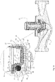
- the bearing retainer flange 43 has initially some lateral wiggle room between the radial outer bearing retainer surface 69 and the first radial inner reference surface 71 of the pump housing 11. This facilitates the insertion of the bearing retainer 41 into the pump housing 11 during assembly.
- the axial pressure exerted by the rotor can flange 63 onto the bearing retainer flange 43 slightly flattens the conical bearing retainer flange section 93, whereby the lateral wiggle room between the radial outer bearing retainer surface 69 and the first radial inner reference surface 71 of the pump housing 11 is closed.
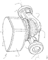
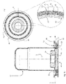
- the impeller 12 may at least partially extend into the circumferential wall section 30 of the neck ring 29, so that it is the radial inner surface 110 of the circumferential wall section 30 which is preferably eccentrically machined with respect to the radial outer surface 105 of the circumferential wall section 30 in order to reduce the gap G.
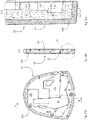
- the inner side of the first material 139 may be at least partially overmoulded with the heat-conductive material 141.
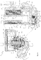
- the heat-conductive material 141 is useful to dissipate heat from the PCB 15 which extends in a plane essentially perpendicular to the rotor axis R close to the inner side of the cap 21.
- the cap 21 comprises a front face 19 that extends essentially parallel to the PCB 15, i.e. essentially perpendicular to the rotor axis R, and a radially outer wall 143 extending essentially parallel to the rotor axis R.
- the lateral location of the injection point(s) of the second material 141 during overmoulding may thus be wisely chosen to define the first area(s) 145, where the hottest electronic components are located on the PCB 15. This facilitates the heat dissipation from the components on the PCB 15 into the second material 141, which spreads the heat laterally via the second area(s) 147.
- the first material 139 may act as a heat sink that is cooled by an ambient convection air stream along the front face 19 and/or the radially outer wall 143 of the cap 21.
Landscapes
- Engineering & Computer Science (AREA)
- Mechanical Engineering (AREA)
- General Engineering & Computer Science (AREA)
- Physics & Mathematics (AREA)
- Thermal Sciences (AREA)
- Microelectronics & Electronic Packaging (AREA)
- Manufacturing & Machinery (AREA)
- Structures Of Non-Positive Displacement Pumps (AREA)
Claims (14)
- Pumpenanordnung (1), umfassend:- eine Rotorwelle (45), die entlang einer Rotorachse (R) verläuft,- ein Laufrad (12), das an der Rotorwelle (45) befestigt ist,- ein Pumpengehäuse (11), das das Laufrad (12) aufnimmt,- einen Antriebsmotor, der einen Stator (17) und einen Rotor (51) umfasst, wobei der Rotor (51) zum Antreiben des Laufrads (12) an der Rotorwelle (45) befestigt ist,- eine Rotordose (57), die den Rotor (51) aufnimmt, wobei die Rotordose (57) einen Rotordosenflansch (63) umfasst, und- ein Elektronikgehäuse (13),wobei das Elektronikgehäuse (13) eine Kappe (21) umfasst, die ein erstes Material (139) umfasst, welches eine Vorderseite (19) der Kappe (21) ausbildet, wobei das erste Material (139) der Kappe (21) zumindest teilweise mit einem zweiten Material (141) an einer Innenseite der Kappe (21) umspritzt ist, wobei das zweite Material (141) wärmeleitfähiger als das erste Material (139) ist, dadurch gekennzeichnet, dassdie Kappe (21) eine radial äußere Wand (143) umfasst, die das erste Material (139) umfasst und im Wesentlichen senkrecht zur Vorderseite (19) verläuft, wobei eine Innenseite der radial äußeren Wand (143) zumindest teilweise mit dem zweiten Material (141) umspritzt ist.
- Pumpenanordnung (1) nach Anspruch 1, wobei das erste Material (139) eine höhere Durchschlagfestigkeit und/oder eine höhere vergleichende Kriechstromzahl (CTI) als das zweite Material (141) aufweist.
- Pumpenanordnung (1) nach einem der vorhergehenden Ansprüche, wobei das zweite Material (141) terrassenförmig an einer Innenseite angeordnet ist, die einer Leiterplatte (PCB) (15) zugekehrt ist, welche im Wesentlichen parallel zur Vorderseite (19) verläuft, um einen axialen direkten oder indirekten thermischen Kontakt zwischen dem zweiten Material (141) und elektronischen Komponenten auf der PCB (15) herzustellen.
- Pumpenanordnung (1) nach einem der vorhergehenden Ansprüche, wobei das zweite Material zumindest einen ersten Bereich (145) mit einer ersten Richtung (149) vorherrschender Wärmeleitung umfasst, die im Wesentlichen senkrecht zur Vorderseite (19) verläuft, und wobei das zweite Material zumindest einen zweiten Bereich (147) mit einer zweiten Richtung (151) vorherrschender Wärmeleitung umfasst, die im Wesentlichen parallel zur Vorderseite (19) verläuft.
- Pumpenanordnung (1) nach Anspruch 4, wobei sich der zumindest eine erste Bereich (145) an oder um Einspritzpunkten zum Umspritzen des ersten Materials (139) der Kappe (21) mit dem zweiten Material (141) befindet.
- Pumpenanordnung (1) nach Anspruch 4 oder 5, wobei der zumindest eine erste Bereich (145) axial in direktem oder indirektem thermischem Kontakt mit jener dieser elektronischen Komponenten auf der PCB (15) ist, die während des Pumpenbetriebs am meisten Wärme ableitet.
- Pumpenanordnung (1) nach einem der vorhergehenden Ansprüche, ferner umfassend:- einen ersten radialen Lagerring (47), der in Gleitkontakt mit der Rotorwelle (45) steht, und- einen Lagerhalter (41), der den ersten radialen Lagerring (47) einfasst und den ersten radialen Lagerring (47) bezüglich der ersten radialen inneren Referenzfläche (71) des Pumpengehäuses (11) zentriert,wobei der Rotordosenflansch (63) einen radialen Abstand zum Pumpengehäuse (11) aufweist und die Rotordose (57) eine radiale innere Zentrierfläche (65) umfasst, die durch radiales Anstoßen an eine radiale äußere Zentrierfläche (67) des Lagerhalters (41) zentriert ist.
- Pumpenanordnung (1) nach Anspruch 7, wobei die radiale innere Zentrierfläche (65) der Rotordose (57) und oder die radiale äußere Zentrierfläche (67) des Lagerhalters (41) zumindest drei radiale Vorsprünge (72) aufweisen.
- Pumpenanordnung (1) nach Anspruch 7 oder 8, wobei der Lagerhalter (41) eine radiale äußere Lagerhalterfläche (69) mit zumindest drei radialen Vorsprüngen (70) umfasst, die radial an die erste radiale innere Referenzfläche (71) des Pumpengehäuses (11) anstößt und den Lagerhalter (41) bezüglich der ersten radialen inneren Referenzfläche (71) des Pumpengehäuses (11) zentriert.
- Pumpenanordnung (1) nach Anspruch 7 bis 9, wobei der Rotordosenflansch (63) eine U-förmige Umfangsnut (73) mit einem radialen inneren Teilabschnitt (75) und einem radialen äußeren Teilabschnitt (77) ausbildet, wobei der radiale innere Teilabschnitt (75) die radiale innere Zentrierfläche (65) der Rotordose (57) ausbildet.
- Pumpenanordnung (1) nach einem der vorhergehenden Ansprüche, ferner umfassend einen Bajonettring (113) zum Befestigen des Elektronikgehäuses (13) am Pumpengehäuse (11), wobei der Bajonettring (113) zum axialen Vorspannen des Elektronikgehäuses (13) an das Pumpengehäuse (11) zum Laufrad (12) hin elastisch vorgespannt ist.
- Verfahren zum Herstellen einer Kappe (21) eines Elektronikgehäuses (13) einer Pumpenanordnung (1) nach einem der Ansprüche 1 bis 11, die folgenden Schritte umfassend:- Ausbilden einer Vorderseite (19) und einer radial äußeren Wand (143) der Kappe (21) aus einem ersten Material (139), wobei die radial äußere Wand (143) im Wesentlichen senkrecht zur Vorderseite (19) verläuft, und- zumindest teilweises Umspritzen des ersten Materials (139) mit einem zweiten Material (141) an einer Innenseite der Vorderseite (19) und zumindest teilweise an einer Innenseite der radial äußeren Wand (143), wobei das zweite Material (141) wärmeleitfähiger als das erste Material (139) ist.
- Verfahren nach Anspruch 12, wobei der zweite Schritt des zumindest teilweisen Umspritzens Einspritzen des zweiten Materials (141) in einem oder mehr Bereichen (145) umfasst, in dem/denen sich jene elektronischen Komponenten auf einer PCB (15), welche im Wesentlichen parallel zur Vorderseite (19) verläuft, befinden, die während des Pumpenbetriebs am meisten Wärme ableiten.
- Verfahren nach Anspruch 12 oder 13, wobei das erste Material (139) eine höhere Durchschlagfestigkeit und/oder eine höhere vergleichende Kriechstromzahl (CTI) als das zweite Material (141) aufweist.
Priority Applications (3)
| Application Number | Priority Date | Filing Date | Title |
|---|---|---|---|
| EP18212317.4A EP3667087B1 (de) | 2018-12-13 | 2018-12-13 | Pumpenanordnung |
| US16/711,865 US11286941B2 (en) | 2018-12-13 | 2019-12-12 | Pump assembly |
| CN201911284024.3A CN111322246B (zh) | 2018-12-13 | 2019-12-13 | 泵机组 |
Applications Claiming Priority (1)
| Application Number | Priority Date | Filing Date | Title |
|---|---|---|---|
| EP18212317.4A EP3667087B1 (de) | 2018-12-13 | 2018-12-13 | Pumpenanordnung |
Publications (2)
| Publication Number | Publication Date |
|---|---|
| EP3667087A1 EP3667087A1 (de) | 2020-06-17 |
| EP3667087B1 true EP3667087B1 (de) | 2022-12-07 |
Family
ID=64665323
Family Applications (1)
| Application Number | Title | Priority Date | Filing Date |
|---|---|---|---|
| EP18212317.4A Active EP3667087B1 (de) | 2018-12-13 | 2018-12-13 | Pumpenanordnung |
Country Status (3)
| Country | Link |
|---|---|
| US (1) | US11286941B2 (de) |
| EP (1) | EP3667087B1 (de) |
| CN (1) | CN111322246B (de) |
Families Citing this family (1)
| Publication number | Priority date | Publication date | Assignee | Title |
|---|---|---|---|---|
| TWI704291B (zh) * | 2019-08-12 | 2020-09-11 | 訊凱國際股份有限公司 | 磁驅泵浦 |
Family Cites Families (19)
| Publication number | Priority date | Publication date | Assignee | Title |
|---|---|---|---|---|
| DE19705974A1 (de) * | 1997-02-17 | 1998-08-20 | Wilo Gmbh | Elektromotor für eine Pumpe oder einen Lüfter |
| US6065946A (en) * | 1997-07-03 | 2000-05-23 | Servo Magnetics, Inc. | Integrated controller pump |
| DE19903078A1 (de) * | 1999-01-27 | 2000-08-03 | Wilo Gmbh | Spalttopf für Kreiselpumpe |
| JP5349005B2 (ja) * | 2007-10-29 | 2013-11-20 | 株式会社山田製作所 | 電動ポンプ |
| EP2072828B1 (de) | 2007-12-17 | 2018-03-28 | Grundfos Management A/S | Nasslaufkreiselpumpe |
| DE102010040267B4 (de) * | 2010-09-03 | 2014-07-17 | Von Ardenne Anlagentechnik Gmbh | Sputtereinrichtung mit rohrförmigem Target |
| JP5316917B2 (ja) | 2010-09-29 | 2013-10-16 | アイシン精機株式会社 | 電動ポンプ |
| PL2500575T5 (pl) * | 2011-03-12 | 2022-10-17 | Grundfos Management A/S | Pompa obiegowa do instalacji grzewczej |
| EP2607707B2 (de) * | 2011-12-23 | 2022-11-23 | Grundfos Holding A/S | Elektromotor |
| EP2750268B1 (de) * | 2012-12-27 | 2015-10-14 | Grundfos Holding A/S | Pumpenaggregat |
| EP2750265B1 (de) * | 2012-12-27 | 2017-11-29 | Grundfos Holding A/S | Pumpenaggregat |
| DE102015106652A1 (de) * | 2014-07-02 | 2016-01-07 | Pierburg Gmbh | Elektrischer Verdichter für eine Verbrennungskraftmaschine |
| JP6320901B2 (ja) * | 2014-11-17 | 2018-05-09 | 株式会社日立製作所 | データ連携支援システムおよびデータ連携支援方法 |
| CN105221441A (zh) * | 2015-09-18 | 2016-01-06 | 河南省西峡汽车水泵股份有限公司 | 一种低能耗高寿命的汽车电动水泵 |
| EP3339656B1 (de) * | 2016-12-22 | 2020-11-11 | Grundfos Holding A/S | Pumpenaggregat |
| EP3382207B1 (de) * | 2017-03-31 | 2021-09-29 | Grundfos Holding A/S | Pumpenanordnung |
| EP3382206B1 (de) * | 2017-03-31 | 2020-12-16 | Grundfos Holding A/S | Pumpenanordnung |
| CN107246396B (zh) * | 2017-07-31 | 2019-11-15 | 广东威灵汽车部件有限公司 | 电子水泵 |
| CN108661920A (zh) * | 2018-03-02 | 2018-10-16 | 安徽达来电机有限公司 | 电子水泵 |
-
2018
- 2018-12-13 EP EP18212317.4A patent/EP3667087B1/de active Active
-
2019
- 2019-12-12 US US16/711,865 patent/US11286941B2/en active Active
- 2019-12-13 CN CN201911284024.3A patent/CN111322246B/zh active Active
Also Published As
| Publication number | Publication date |
|---|---|
| CN111322246A (zh) | 2020-06-23 |
| EP3667087A1 (de) | 2020-06-17 |
| US11286941B2 (en) | 2022-03-29 |
| US20200191166A1 (en) | 2020-06-18 |
| CN111322246B (zh) | 2022-02-25 |
Similar Documents
| Publication | Publication Date | Title |
|---|---|---|
| EP3667092B1 (de) | Pumpenanordnung | |
| US10941782B2 (en) | Pump assembly | |
| US9568012B2 (en) | Pump, refrigeration cycle apparatus, and method for manufacturing pump | |
| US20030057781A1 (en) | Brushless DC motor, pump, and electronic apparatus | |
| EP3667087B1 (de) | Pumpenanordnung | |
| US11848588B2 (en) | Motor integrated with control unit and water pump having the same | |
| EP3667088A1 (de) | Pumpenanordnung | |
| CN111255715B (zh) | 马达和风扇马达 | |
| US10900487B2 (en) | Pump assembly | |
| EP3667091B1 (de) | Pumpenanordnung | |
| EP3667090B1 (de) | Pumpenanordnung | |
| US11085462B2 (en) | Pump assembly | |
| EP3667099A1 (de) | Pumpenanordnung | |
| US10550851B2 (en) | Fan having an impeller including a resin portion and a metal plate |
Legal Events
| Date | Code | Title | Description |
|---|---|---|---|
| PUAI | Public reference made under article 153(3) epc to a published international application that has entered the european phase |
Free format text: ORIGINAL CODE: 0009012 |
|
| STAA | Information on the status of an ep patent application or granted ep patent |
Free format text: STATUS: THE APPLICATION HAS BEEN PUBLISHED |
|
| AK | Designated contracting states |
Kind code of ref document: A1 Designated state(s): AL AT BE BG CH CY CZ DE DK EE ES FI FR GB GR HR HU IE IS IT LI LT LU LV MC MK MT NL NO PL PT RO RS SE SI SK SM TR |
|
| AX | Request for extension of the european patent |
Extension state: BA ME |
|
| STAA | Information on the status of an ep patent application or granted ep patent |
Free format text: STATUS: REQUEST FOR EXAMINATION WAS MADE |
|
| 17P | Request for examination filed |
Effective date: 20201207 |
|
| RBV | Designated contracting states (corrected) |
Designated state(s): AL AT BE BG CH CY CZ DE DK EE ES FI FR GB GR HR HU IE IS IT LI LT LU LV MC MK MT NL NO PL PT RO RS SE SI SK SM TR |
|
| GRAP | Despatch of communication of intention to grant a patent |
Free format text: ORIGINAL CODE: EPIDOSNIGR1 |
|
| STAA | Information on the status of an ep patent application or granted ep patent |
Free format text: STATUS: GRANT OF PATENT IS INTENDED |
|
| INTG | Intention to grant announced |
Effective date: 20220622 |
|
| GRAS | Grant fee paid |
Free format text: ORIGINAL CODE: EPIDOSNIGR3 |
|
| GRAA | (expected) grant |
Free format text: ORIGINAL CODE: 0009210 |
|
| STAA | Information on the status of an ep patent application or granted ep patent |
Free format text: STATUS: THE PATENT HAS BEEN GRANTED |
|
| AK | Designated contracting states |
Kind code of ref document: B1 Designated state(s): AL AT BE BG CH CY CZ DE DK EE ES FI FR GB GR HR HU IE IS IT LI LT LU LV MC MK MT NL NO PL PT RO RS SE SI SK SM TR |
|
| REG | Reference to a national code |
Ref country code: GB Ref legal event code: FG4D |
|
| REG | Reference to a national code |
Ref country code: CH Ref legal event code: EP Ref country code: AT Ref legal event code: REF Ref document number: 1536470 Country of ref document: AT Kind code of ref document: T Effective date: 20221215 |
|
| REG | Reference to a national code |
Ref country code: DE Ref legal event code: R096 Ref document number: 602018043922 Country of ref document: DE |
|
| REG | Reference to a national code |
Ref country code: IE Ref legal event code: FG4D |
|
| REG | Reference to a national code |
Ref country code: LT Ref legal event code: MG9D |
|
| REG | Reference to a national code |
Ref country code: NL Ref legal event code: MP Effective date: 20221207 |
|
| PG25 | Lapsed in a contracting state [announced via postgrant information from national office to epo] |
Ref country code: SE Free format text: LAPSE BECAUSE OF FAILURE TO SUBMIT A TRANSLATION OF THE DESCRIPTION OR TO PAY THE FEE WITHIN THE PRESCRIBED TIME-LIMIT Effective date: 20221207 Ref country code: NO Free format text: LAPSE BECAUSE OF FAILURE TO SUBMIT A TRANSLATION OF THE DESCRIPTION OR TO PAY THE FEE WITHIN THE PRESCRIBED TIME-LIMIT Effective date: 20230307 Ref country code: LT Free format text: LAPSE BECAUSE OF FAILURE TO SUBMIT A TRANSLATION OF THE DESCRIPTION OR TO PAY THE FEE WITHIN THE PRESCRIBED TIME-LIMIT Effective date: 20221207 Ref country code: FI Free format text: LAPSE BECAUSE OF FAILURE TO SUBMIT A TRANSLATION OF THE DESCRIPTION OR TO PAY THE FEE WITHIN THE PRESCRIBED TIME-LIMIT Effective date: 20221207 Ref country code: ES Free format text: LAPSE BECAUSE OF FAILURE TO SUBMIT A TRANSLATION OF THE DESCRIPTION OR TO PAY THE FEE WITHIN THE PRESCRIBED TIME-LIMIT Effective date: 20221207 |
|
| REG | Reference to a national code |
Ref country code: AT Ref legal event code: MK05 Ref document number: 1536470 Country of ref document: AT Kind code of ref document: T Effective date: 20221207 |
|
| PG25 | Lapsed in a contracting state [announced via postgrant information from national office to epo] |
Ref country code: RS Free format text: LAPSE BECAUSE OF FAILURE TO SUBMIT A TRANSLATION OF THE DESCRIPTION OR TO PAY THE FEE WITHIN THE PRESCRIBED TIME-LIMIT Effective date: 20221207 Ref country code: PL Free format text: LAPSE BECAUSE OF FAILURE TO SUBMIT A TRANSLATION OF THE DESCRIPTION OR TO PAY THE FEE WITHIN THE PRESCRIBED TIME-LIMIT Effective date: 20221207 Ref country code: LV Free format text: LAPSE BECAUSE OF FAILURE TO SUBMIT A TRANSLATION OF THE DESCRIPTION OR TO PAY THE FEE WITHIN THE PRESCRIBED TIME-LIMIT Effective date: 20221207 Ref country code: HR Free format text: LAPSE BECAUSE OF FAILURE TO SUBMIT A TRANSLATION OF THE DESCRIPTION OR TO PAY THE FEE WITHIN THE PRESCRIBED TIME-LIMIT Effective date: 20221207 Ref country code: GR Free format text: LAPSE BECAUSE OF FAILURE TO SUBMIT A TRANSLATION OF THE DESCRIPTION OR TO PAY THE FEE WITHIN THE PRESCRIBED TIME-LIMIT Effective date: 20230308 |
|
| PG25 | Lapsed in a contracting state [announced via postgrant information from national office to epo] |
Ref country code: NL Free format text: LAPSE BECAUSE OF FAILURE TO SUBMIT A TRANSLATION OF THE DESCRIPTION OR TO PAY THE FEE WITHIN THE PRESCRIBED TIME-LIMIT Effective date: 20221207 |
|
| REG | Reference to a national code |
Ref country code: DE Ref legal event code: R119 Ref document number: 602018043922 Country of ref document: DE |
|
| PG25 | Lapsed in a contracting state [announced via postgrant information from national office to epo] |
Ref country code: SM Free format text: LAPSE BECAUSE OF FAILURE TO SUBMIT A TRANSLATION OF THE DESCRIPTION OR TO PAY THE FEE WITHIN THE PRESCRIBED TIME-LIMIT Effective date: 20221207 Ref country code: RO Free format text: LAPSE BECAUSE OF FAILURE TO SUBMIT A TRANSLATION OF THE DESCRIPTION OR TO PAY THE FEE WITHIN THE PRESCRIBED TIME-LIMIT Effective date: 20221207 Ref country code: PT Free format text: LAPSE BECAUSE OF FAILURE TO SUBMIT A TRANSLATION OF THE DESCRIPTION OR TO PAY THE FEE WITHIN THE PRESCRIBED TIME-LIMIT Effective date: 20230410 Ref country code: EE Free format text: LAPSE BECAUSE OF FAILURE TO SUBMIT A TRANSLATION OF THE DESCRIPTION OR TO PAY THE FEE WITHIN THE PRESCRIBED TIME-LIMIT Effective date: 20221207 Ref country code: CZ Free format text: LAPSE BECAUSE OF FAILURE TO SUBMIT A TRANSLATION OF THE DESCRIPTION OR TO PAY THE FEE WITHIN THE PRESCRIBED TIME-LIMIT Effective date: 20221207 Ref country code: AT Free format text: LAPSE BECAUSE OF FAILURE TO SUBMIT A TRANSLATION OF THE DESCRIPTION OR TO PAY THE FEE WITHIN THE PRESCRIBED TIME-LIMIT Effective date: 20221207 |
|
| REG | Reference to a national code |
Ref country code: CH Ref legal event code: PL |
|
| REG | Reference to a national code |
Ref country code: BE Ref legal event code: MM Effective date: 20221231 |
|
| PG25 | Lapsed in a contracting state [announced via postgrant information from national office to epo] |
Ref country code: SK Free format text: LAPSE BECAUSE OF FAILURE TO SUBMIT A TRANSLATION OF THE DESCRIPTION OR TO PAY THE FEE WITHIN THE PRESCRIBED TIME-LIMIT Effective date: 20221207 Ref country code: LU Free format text: LAPSE BECAUSE OF NON-PAYMENT OF DUE FEES Effective date: 20221213 Ref country code: IS Free format text: LAPSE BECAUSE OF FAILURE TO SUBMIT A TRANSLATION OF THE DESCRIPTION OR TO PAY THE FEE WITHIN THE PRESCRIBED TIME-LIMIT Effective date: 20230407 Ref country code: AL Free format text: LAPSE BECAUSE OF FAILURE TO SUBMIT A TRANSLATION OF THE DESCRIPTION OR TO PAY THE FEE WITHIN THE PRESCRIBED TIME-LIMIT Effective date: 20221207 |
|
| PG25 | Lapsed in a contracting state [announced via postgrant information from national office to epo] |
Ref country code: MC Free format text: LAPSE BECAUSE OF FAILURE TO SUBMIT A TRANSLATION OF THE DESCRIPTION OR TO PAY THE FEE WITHIN THE PRESCRIBED TIME-LIMIT Effective date: 20221207 |
|
| PLBE | No opposition filed within time limit |
Free format text: ORIGINAL CODE: 0009261 |
|
| STAA | Information on the status of an ep patent application or granted ep patent |
Free format text: STATUS: NO OPPOSITION FILED WITHIN TIME LIMIT |
|
| PG25 | Lapsed in a contracting state [announced via postgrant information from national office to epo] |
Ref country code: LI Free format text: LAPSE BECAUSE OF NON-PAYMENT OF DUE FEES Effective date: 20221231 Ref country code: IE Free format text: LAPSE BECAUSE OF NON-PAYMENT OF DUE FEES Effective date: 20221213 Ref country code: DK Free format text: LAPSE BECAUSE OF FAILURE TO SUBMIT A TRANSLATION OF THE DESCRIPTION OR TO PAY THE FEE WITHIN THE PRESCRIBED TIME-LIMIT Effective date: 20221207 Ref country code: DE Free format text: LAPSE BECAUSE OF NON-PAYMENT OF DUE FEES Effective date: 20230701 Ref country code: CH Free format text: LAPSE BECAUSE OF NON-PAYMENT OF DUE FEES Effective date: 20221231 |
|
| 26N | No opposition filed |
Effective date: 20230908 |
|
| GBPC | Gb: european patent ceased through non-payment of renewal fee |
Effective date: 20230307 |
|
| PG25 | Lapsed in a contracting state [announced via postgrant information from national office to epo] |
Ref country code: SI Free format text: LAPSE BECAUSE OF FAILURE TO SUBMIT A TRANSLATION OF THE DESCRIPTION OR TO PAY THE FEE WITHIN THE PRESCRIBED TIME-LIMIT Effective date: 20221207 Ref country code: BE Free format text: LAPSE BECAUSE OF NON-PAYMENT OF DUE FEES Effective date: 20221231 |
|
| PG25 | Lapsed in a contracting state [announced via postgrant information from national office to epo] |
Ref country code: GB Free format text: LAPSE BECAUSE OF NON-PAYMENT OF DUE FEES Effective date: 20230307 |
|
| PG25 | Lapsed in a contracting state [announced via postgrant information from national office to epo] |
Ref country code: GB Free format text: LAPSE BECAUSE OF NON-PAYMENT OF DUE FEES Effective date: 20230307 Ref country code: FR Free format text: LAPSE BECAUSE OF NON-PAYMENT OF DUE FEES Effective date: 20230207 |
|
| PG25 | Lapsed in a contracting state [announced via postgrant information from national office to epo] |
Ref country code: HU Free format text: LAPSE BECAUSE OF FAILURE TO SUBMIT A TRANSLATION OF THE DESCRIPTION OR TO PAY THE FEE WITHIN THE PRESCRIBED TIME-LIMIT; INVALID AB INITIO Effective date: 20181213 |
|
| PG25 | Lapsed in a contracting state [announced via postgrant information from national office to epo] |
Ref country code: CY Free format text: LAPSE BECAUSE OF FAILURE TO SUBMIT A TRANSLATION OF THE DESCRIPTION OR TO PAY THE FEE WITHIN THE PRESCRIBED TIME-LIMIT Effective date: 20221207 |