EP3667059A1 - A large two-stroke compression-ignited internal combustion engine with fuel injection system for a low flashpoint fuel and a fuel valve therefore - Google Patents
A large two-stroke compression-ignited internal combustion engine with fuel injection system for a low flashpoint fuel and a fuel valve therefore Download PDFInfo
- Publication number
- EP3667059A1 EP3667059A1 EP19213763.6A EP19213763A EP3667059A1 EP 3667059 A1 EP3667059 A1 EP 3667059A1 EP 19213763 A EP19213763 A EP 19213763A EP 3667059 A1 EP3667059 A1 EP 3667059A1
- Authority
- EP
- European Patent Office
- Prior art keywords
- fuel
- valve
- bore
- actuation
- needle
- Prior art date
- Legal status (The legal status is an assumption and is not a legal conclusion. Google has not performed a legal analysis and makes no representation as to the accuracy of the status listed.)
- Granted
Links
- 239000000446 fuel Substances 0.000 title claims abstract description 287
- 238000002485 combustion reaction Methods 0.000 title claims abstract description 39
- 238000002347 injection Methods 0.000 title description 43
- 239000007924 injection Substances 0.000 title description 43
- 239000007788 liquid Substances 0.000 claims abstract description 114
- 238000007789 sealing Methods 0.000 claims abstract description 51
- 239000012530 fluid Substances 0.000 claims abstract description 27
- 239000007789 gas Substances 0.000 description 18
- 239000003921 oil Substances 0.000 description 14
- OKKJLVBELUTLKV-UHFFFAOYSA-N Methanol Chemical compound OC OKKJLVBELUTLKV-UHFFFAOYSA-N 0.000 description 9
- 239000003915 liquefied petroleum gas Substances 0.000 description 8
- LCGLNKUTAGEVQW-UHFFFAOYSA-N Dimethyl ether Chemical compound COC LCGLNKUTAGEVQW-UHFFFAOYSA-N 0.000 description 6
- 239000010763 heavy fuel oil Substances 0.000 description 6
- 239000000295 fuel oil Substances 0.000 description 5
- 230000006835 compression Effects 0.000 description 4
- 238000007906 compression Methods 0.000 description 4
- 230000001419 dependent effect Effects 0.000 description 4
- 239000000203 mixture Substances 0.000 description 4
- 238000005461 lubrication Methods 0.000 description 3
- LFQSCWFLJHTTHZ-UHFFFAOYSA-N Ethanol Chemical compound CCO LFQSCWFLJHTTHZ-UHFFFAOYSA-N 0.000 description 2
- 239000002826 coolant Substances 0.000 description 2
- 238000001816 cooling Methods 0.000 description 2
- 238000001514 detection method Methods 0.000 description 2
- 238000010586 diagram Methods 0.000 description 2
- 230000009977 dual effect Effects 0.000 description 2
- 239000003502 gasoline Substances 0.000 description 2
- 230000002000 scavenging effect Effects 0.000 description 2
- 229910000831 Steel Inorganic materials 0.000 description 1
- 229910001315 Tool steel Inorganic materials 0.000 description 1
- 239000003225 biodiesel Substances 0.000 description 1
- 239000002551 biofuel Substances 0.000 description 1
- 239000003250 coal slurry Substances 0.000 description 1
- 238000010276 construction Methods 0.000 description 1
- 230000001276 controlling effect Effects 0.000 description 1
- 239000010779 crude oil Substances 0.000 description 1
- 230000007613 environmental effect Effects 0.000 description 1
- 239000002360 explosive Substances 0.000 description 1
- 230000000977 initiatory effect Effects 0.000 description 1
- 239000010687 lubricating oil Substances 0.000 description 1
- 238000012544 monitoring process Methods 0.000 description 1
- -1 naphtha Substances 0.000 description 1
- 230000010355 oscillation Effects 0.000 description 1
- 239000002006 petroleum coke Substances 0.000 description 1
- 230000001105 regulatory effect Effects 0.000 description 1
- 238000007493 shaping process Methods 0.000 description 1
- 229910001220 stainless steel Inorganic materials 0.000 description 1
- 239000010935 stainless steel Substances 0.000 description 1
- 239000010959 steel Substances 0.000 description 1
- 230000032258 transport Effects 0.000 description 1
Images


Classifications
-
- F—MECHANICAL ENGINEERING; LIGHTING; HEATING; WEAPONS; BLASTING
- F02—COMBUSTION ENGINES; HOT-GAS OR COMBUSTION-PRODUCT ENGINE PLANTS
- F02M—SUPPLYING COMBUSTION ENGINES IN GENERAL WITH COMBUSTIBLE MIXTURES OR CONSTITUENTS THEREOF
- F02M21/00—Apparatus for supplying engines with non-liquid fuels, e.g. gaseous fuels stored in liquid form
- F02M21/02—Apparatus for supplying engines with non-liquid fuels, e.g. gaseous fuels stored in liquid form for gaseous fuels
- F02M21/0218—Details on the gaseous fuel supply system, e.g. tanks, valves, pipes, pumps, rails, injectors or mixers
- F02M21/023—Valves; Pressure or flow regulators in the fuel supply or return system
-
- F—MECHANICAL ENGINEERING; LIGHTING; HEATING; WEAPONS; BLASTING
- F02—COMBUSTION ENGINES; HOT-GAS OR COMBUSTION-PRODUCT ENGINE PLANTS
- F02M—SUPPLYING COMBUSTION ENGINES IN GENERAL WITH COMBUSTIBLE MIXTURES OR CONSTITUENTS THEREOF
- F02M43/00—Fuel-injection apparatus operating simultaneously on two or more fuels, or on a liquid fuel and another liquid, e.g. the other liquid being an anti-knock additive
- F02M43/04—Injectors peculiar thereto
-
- F—MECHANICAL ENGINEERING; LIGHTING; HEATING; WEAPONS; BLASTING
- F02—COMBUSTION ENGINES; HOT-GAS OR COMBUSTION-PRODUCT ENGINE PLANTS
- F02M—SUPPLYING COMBUSTION ENGINES IN GENERAL WITH COMBUSTIBLE MIXTURES OR CONSTITUENTS THEREOF
- F02M57/00—Fuel-injectors combined or associated with other devices
- F02M57/02—Injectors structurally combined with fuel-injection pumps
- F02M57/022—Injectors structurally combined with fuel-injection pumps characterised by the pump drive
- F02M57/025—Injectors structurally combined with fuel-injection pumps characterised by the pump drive hydraulic, e.g. with pressure amplification
- F02M57/026—Construction details of pressure amplifiers, e.g. fuel passages or check valves arranged in the intensifier piston or head, particular diameter relationships, stop members, arrangement of ports or conduits
-
- F—MECHANICAL ENGINEERING; LIGHTING; HEATING; WEAPONS; BLASTING
- F02—COMBUSTION ENGINES; HOT-GAS OR COMBUSTION-PRODUCT ENGINE PLANTS
- F02M—SUPPLYING COMBUSTION ENGINES IN GENERAL WITH COMBUSTIBLE MIXTURES OR CONSTITUENTS THEREOF
- F02M61/00—Fuel-injectors not provided for in groups F02M39/00 - F02M57/00 or F02M67/00
- F02M61/04—Fuel-injectors not provided for in groups F02M39/00 - F02M57/00 or F02M67/00 having valves, e.g. having a plurality of valves in series
- F02M61/10—Other injectors with elongated valve bodies, i.e. of needle-valve type
-
- F—MECHANICAL ENGINEERING; LIGHTING; HEATING; WEAPONS; BLASTING
- F02—COMBUSTION ENGINES; HOT-GAS OR COMBUSTION-PRODUCT ENGINE PLANTS
- F02B—INTERNAL-COMBUSTION PISTON ENGINES; COMBUSTION ENGINES IN GENERAL
- F02B25/00—Engines characterised by using fresh charge for scavenging cylinders
- F02B25/02—Engines characterised by using fresh charge for scavenging cylinders using unidirectional scavenging
-
- F—MECHANICAL ENGINEERING; LIGHTING; HEATING; WEAPONS; BLASTING
- F02—COMBUSTION ENGINES; HOT-GAS OR COMBUSTION-PRODUCT ENGINE PLANTS
- F02B—INTERNAL-COMBUSTION PISTON ENGINES; COMBUSTION ENGINES IN GENERAL
- F02B43/00—Engines characterised by operating on gaseous fuels; Plants including such engines
- F02B43/02—Engines characterised by means for increasing operating efficiency
-
- F—MECHANICAL ENGINEERING; LIGHTING; HEATING; WEAPONS; BLASTING
- F02—COMBUSTION ENGINES; HOT-GAS OR COMBUSTION-PRODUCT ENGINE PLANTS
- F02B—INTERNAL-COMBUSTION PISTON ENGINES; COMBUSTION ENGINES IN GENERAL
- F02B43/00—Engines characterised by operating on gaseous fuels; Plants including such engines
- F02B43/10—Engines or plants characterised by use of other specific gases, e.g. acetylene, oxyhydrogen
-
- F—MECHANICAL ENGINEERING; LIGHTING; HEATING; WEAPONS; BLASTING
- F02—COMBUSTION ENGINES; HOT-GAS OR COMBUSTION-PRODUCT ENGINE PLANTS
- F02D—CONTROLLING COMBUSTION ENGINES
- F02D19/00—Controlling engines characterised by their use of non-liquid fuels, pluralities of fuels, or non-fuel substances added to the combustible mixtures
- F02D19/06—Controlling engines characterised by their use of non-liquid fuels, pluralities of fuels, or non-fuel substances added to the combustible mixtures peculiar to engines working with pluralities of fuels, e.g. alternatively with light and heavy fuel oil, other than engines indifferent to the fuel consumed
-
- F—MECHANICAL ENGINEERING; LIGHTING; HEATING; WEAPONS; BLASTING
- F02—COMBUSTION ENGINES; HOT-GAS OR COMBUSTION-PRODUCT ENGINE PLANTS
- F02M—SUPPLYING COMBUSTION ENGINES IN GENERAL WITH COMBUSTIBLE MIXTURES OR CONSTITUENTS THEREOF
- F02M21/00—Apparatus for supplying engines with non-liquid fuels, e.g. gaseous fuels stored in liquid form
- F02M21/02—Apparatus for supplying engines with non-liquid fuels, e.g. gaseous fuels stored in liquid form for gaseous fuels
- F02M21/0218—Details on the gaseous fuel supply system, e.g. tanks, valves, pipes, pumps, rails, injectors or mixers
- F02M21/0248—Injectors
- F02M21/0257—Details of the valve closing elements, e.g. valve seats, stems or arrangement of flow passages
- F02M21/026—Lift valves, i.e. stem operated valves
- F02M21/0263—Inwardly opening single or multi nozzle valves, e.g. needle valves
-
- F—MECHANICAL ENGINEERING; LIGHTING; HEATING; WEAPONS; BLASTING
- F02—COMBUSTION ENGINES; HOT-GAS OR COMBUSTION-PRODUCT ENGINE PLANTS
- F02M—SUPPLYING COMBUSTION ENGINES IN GENERAL WITH COMBUSTIBLE MIXTURES OR CONSTITUENTS THEREOF
- F02M57/00—Fuel-injectors combined or associated with other devices
- F02M57/02—Injectors structurally combined with fuel-injection pumps
-
- F—MECHANICAL ENGINEERING; LIGHTING; HEATING; WEAPONS; BLASTING
- F02—COMBUSTION ENGINES; HOT-GAS OR COMBUSTION-PRODUCT ENGINE PLANTS
- F02M—SUPPLYING COMBUSTION ENGINES IN GENERAL WITH COMBUSTIBLE MIXTURES OR CONSTITUENTS THEREOF
- F02M61/00—Fuel-injectors not provided for in groups F02M39/00 - F02M57/00 or F02M67/00
- F02M61/16—Details not provided for in, or of interest apart from, the apparatus of groups F02M61/02 - F02M61/14
- F02M61/18—Injection nozzles, e.g. having valve seats; Details of valve member seated ends, not otherwise provided for
-
- F—MECHANICAL ENGINEERING; LIGHTING; HEATING; WEAPONS; BLASTING
- F02—COMBUSTION ENGINES; HOT-GAS OR COMBUSTION-PRODUCT ENGINE PLANTS
- F02B—INTERNAL-COMBUSTION PISTON ENGINES; COMBUSTION ENGINES IN GENERAL
- F02B75/00—Other engines
- F02B75/02—Engines characterised by their cycles, e.g. six-stroke
- F02B2075/022—Engines characterised by their cycles, e.g. six-stroke having less than six strokes per cycle
- F02B2075/025—Engines characterised by their cycles, e.g. six-stroke having less than six strokes per cycle two
Definitions
- the disclosure relates to large slow-running two-stroke compression-ignited internal combustion crosshead engines with a fuel injection system for injecting a low flashpoint fuel into the combustion chambers.
- low flashpoint fuels such as e.g. methanol, ethanol, LPG, DME or biofuel, naphtha, gasoline (petrol), crude gasoline and crude oil are relatively clean fuels that result in significantly lower levels of sulfurous components, NOx and CO2 in the exhaust gas when used as fuel for a large low-speed uniflow turbocharged two-stroke internal combustion engine when compared with e.g. using heavy fuel oil as fuel.
- the known common rail type gaseous fuel supply systems for large two-stroke compression-ignited internal combustion engines have disadvantages when operating on LPG or any other similar low flashpoint fuel with a relatively high compressibility.
- the injection pressure for LPG needs to be as high as 600 bar, which means that the common rail system including all valves, accumulators, pipes, etc., needs to be laid out for this high pressure.
- the safety concept with the window valves is not well suited for dense gas like LPG, since firstly the gas channels between window valve and fuel valve need to have a very small volume and secondly, monitoring of the gas channel pressure necessary to ensure detection of leakages is made very difficult due to high frequency oscillation excited from closing of the window valve.
- EP3252291 discloses a fuel supply system according to the preamble of claim 1 that allows precise timing of the injection of the low flashpoint (and more compressible compared to fuel) fuel, using a pressure booster.
- a fuel valve for injecting low flashpoint liquid fuel into the combustion chamber of a large slow running two-stroke turbocharged compression-igniting internal combustion engine comprising:
- the ignition liquid By providing an inlet port for ignition liquid and by providing a conduit that transports the ignition liquid to the first bore for sealing the pump piston in the first bore with an overpressure the ignition liquid will seal the pump piston and ignition liquid will reach the pump chamber since the clearance opens to the pump chamber.
- a small quantity of ignition liquid reaches the pump chamber and is mixed with the low flashpoint fuel.
- the small quantity of ignition liquid mixed with the flow flashpoint fuel is pumped to the nozzle and injected into the combustion chamber. The presence of the ignition liquid mixed with the low flashpoint fuel enhances reliable ignition.
- the pump piston is sealed in the first bore by the ignition liquid delivered via the ignition liquid conduit to the clearance.
- the clearance opens to the pump chamber and the ignition liquid is delivered to the pump chamber via the clearance.
- the flow path comprises a conduit in the valve housing connected to the sealing liquid inlet port and/or a spring chamber of a spring that biases the valve needle to the valve seat and/or an axial bore in the valve needle and/or a transverse bore in the valve needle.
- the sealing oil flow path connects the sealing liquid inlet port to the longitudinal bore at a first position along the length of the longitudinal bore for sealing the valve needle in the longitudinal bore.
- the low-pressure conduit connects the low flashpoint fuel inlet port to the longitudinal bore at a second position along the length of the longitudinal bore, the second position being closer to the fuel cavity than the first position.
- the pressure in the low-pressure conduit is significantly lower than the injection pressure and thus, the connection to the low-pressure conduit "punctures" the high-pressure coming from the fuel cavity and thus, the sealing oil only needs to seal the clearance between the valve needle and the longitudinal bore against the lower fuel pressure in the low-pressure conduit.
- valve needle rests on a valve seat in the closed position and the valve needle has lift from the valve seat in the open position.
- the nozzle has a nozzle body that is secured to the front of the elongated valve housing.
- valve seat is located in the tip of the nozzle.
- the longitudinal bore is formed at least partially in the nozzle body.
- the lift of the valve needle is controlled by the fuel pressure in the fuel cavity.
- valve needle is operably connected to a needle actuation piston with a pressure surface of the needle actuation piston facing a needle actuation chamber in the fuel valve, the needle actuation chamber being fluidically connected to a control port in the fuel valve for connection to a controllable source of control fluid.
- the fuel valve is provided with a valve needle that controls the flow of fuel to nozzle holes of the nozzle of the fuel valve, the position of the valve needle preferably being controlled by a control signal and not by the fuel pressure.
- the pump chamber has an inlet fluidically connected to the fuel inlet port via a first one-way valve.
- the pump chamber having an outlet fluidically connected to the fuel cavity via a second one-way valve.
- the effective pressure area of the pump piston is smaller than the effective pressure area of the actuation piston.
- the nozzle is part of a nozzle body that is secured to the front of the elongated valve housing.
- the inlet is located in the pump piston.
- a first one-way valve is provided in the inlet, the first one-way valve being configured to allow flow of low flashpoint fuel through the inlet into the pump chamber and to prevent flow from the pump chamber into the inlet.
- the outlet of the pump chamber is connected to the fuel cavity by one or more fuel channels.
- a second one-way valve is provided in the one or more fuel channels, the second one-way valve being configured to allow flow of low flashpoint fuel from the pump chamber to the fuel cavity and to prevent flow from the fuel cavity to the pump chamber.
- the pump piston is operably connected to the actuation piston to move in unison therewith.
- a large two-stroke turbocharged compression-ignited internal combustion crosshead engine comprising:
- the pressure of the source of pressurized ignition liquid is electronically controllable, and the engine comprises an electronic control unit configured to control the pressure of the source of pressurized ignition liquid.
- the engine is provided with a non-low flashpoint fuel supply system, and wherein the cylinders are provided with two or more fuel valves for injecting the non-low flashpoint fuel into the cylinders.
- an internal combustion engine will be described with reference to a large two-stroke low-speed uniflow turbocharged compression-ignited internal combustion engine with crossheads in the example embodiments, but it is understood that the internal combustion engine could be of another type, such as a two-stroke Otto, a four-stroke Otto or Diesel, with or without turbocharging, with or without exhaust gas recirculation.
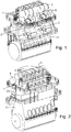
- Figs. 1, 2 and 3 show a large low-speed turbocharged two-stroke diesel engine with a crankshaft 8 and crossheads 9.
- Fig. 3 shows a diagrammatic representation of a large low-speed turbocharged two-stroke diesel engine with its intake and exhaust systems.
- the engine has six cylinders in line.
- Large low-speed turbocharged two-stroke diesel engines have typically between four and fourteen cylinders in line, carried by a cylinder frame 23 that is carried by an engine frame 11.
- the engine may e.g. be used as the main engine in a marine vessel or as a stationary engine for operating a generator in a power station.
- the total output of the engine may, for example, range from 1,000 to 110,000 kW.
- the engine is in this example embodiment a compression-ignited engine of the two-stroke uniflow type with scavenge ports 18 at the lower region of the cylinder liners 1 and a central exhaust valve 4 at the top of the cylinder liners 1.
- the scavenge air is passed from the scavenge air receiver 2 to the scavenge ports 18 of the individual cylinders 1.
- a piston 10 in the cylinder liner 1 compresses the scavenge air.
- Fuel is injected through fuel valves 50 in the cylinder cover 22. Combustion follows, and exhaust gas is generated.
- the fuel valves 50 are suitable for injecting a low flashpoint fuel into the combustion chamber.
- the engine is additionally provided with fuel valves 51 that are suitable for injecting a conventional (non-low flashpoint fuel, such as e.g. fuel oil or heavy fuel oil) fuel into the combustion chamber.
- the exhaust gas flows through an exhaust duct associated with the cylinders 1 into the exhaust gas receiver 3 and onwards through a first exhaust conduit 19 to a turbine 6 of the turbocharger 5, from which the exhaust gas flows away through a second exhaust conduit via an economizer 20 to an outlet 21 and into the atmosphere.
- the turbine 6 drives a compressor 7 supplied with fresh air via an air inlet 12.
- the compressor 7 delivers pressurized scavenge air to a scavenge air conduit 13 leading to the scavenge air receiver 2.
- the scavenge air in the scavenge air conduit 13 passes an intercooler 14 for cooling the scavenge air.
- the cooled scavenge air passes via an auxiliary blower 16 driven by an electric motor 17 that pressurizes the scavenge air flow when the compressor 7 of the turbocharger 5 does not deliver sufficient pressure for the scavenge air receiver 2, i.e. in low or partial load conditions of the engine.
- the turbocharger compressor 7 delivers sufficient compressed scavenge air and then the auxiliary blower 16 is bypassed via a non-return valve 15.
- the engine is operated with a low flashpoint fuel, such as e.g. LPG, methanol or naphtha and supplied by a low flashpoint fuel supply system 30 in liquid or supercritical form at a substantially stable pressure and temperature.
- the engine is a dual fuel engine and is also provided with a conventional fuel supply system (not shown) for supplying a non-low flashpoint fuel, such as e.g. fuel oil or heavy fuel oil.
- a non-low flashpoint fuel such as e.g. fuel oil or heavy fuel oil.
- the low flashpoint fuel supply system 30 supplies fuel injection valves 50 with low flashpoint fuel at relatively low supply pressure (e.g. 8 to 100 bar pressure) via a supply conduit 31.
- Fig. 4a is a diagram showing the fuel injection system that receives the low flashpoint fuel via the supply conduit 31.
- the fuel injection system comprises a pressure booster 40 for pressurizing the fuel to the injection pressure.
- the pressure booster 40 is hydraulically actuated under control of a first control valve 41.
- the fuel valves 50 are hydraulically actuated under control of a second control valve 45.
- FIG. 4a shows the fuel injection system for a single cylinder 1, with one pressure booster 40 and three fuel injection valves 50. Instead of three, there could also be two fuel valves 50 for each cylinder 1. Each cylinder 1 will require a pressure booster 40 supplying two or three fuel valves 50.
- the pressure booster 40 comprises a large diameter plunger connected to a smaller diameter plunger to move in unison therewith.
- the large diameter plunger and the small diameter plunger are received in respective matching bores in the housing of the pressure booster 40.
- the large diameter plunger faces an actuation chamber that is supplied with high pressure hydraulic fluid or with tank under control of the first control valve 41.
- the small diameter plunger faces a pump chamber that is connected to the fuel supply conduit 31 via a one-way valve and to a high-pressure fuel supply line 35 for the delivery of high pressure fuel to the fuel valves 50.
- a one-way valve prevents backflow of fuel from the high-pressure fuel supply line 35 to the pump chamber.
- the pressure of the fuel in the supply conduit 31 is sufficient to cause the pressure booster 40 to make a return stroke when the actuation chamber is connected to tank.
- a position sensor 34 senses the position of the large and small diameter plungers.
- the first control valve 41 comprises a preferably proportional first hydraulically controlled three-way valve 42.
- the first three-way valve 42 is connected to the actuation chamber via an actuation conduit 44, to a source of high-pressure hydraulic fluid and to tank.
- the first three-way valve 42 is configured to connect the actuation chamber selectively to tank or to the source of high-pressure hydraulic fluid. Since the first hydraulically controlled three-way valve 42 is in an embodiment a proportional valve capable of assuming any intermediate position between connection to the source of high-pressure hydraulic fluid and tank.
- the position of the first three-way valve 42 is controlled by a first smaller two-way valve 43 and the position of the first smaller two-way valve 43 is electronically controlled.
- the first smaller two-way valve 43 is connected to an electronic control unit 25 via a first signal cable 26.
- the first control valve 41 is under command of a separate electronic control unit that is mainly configured for maintaining safety and will deactivate the pressure booster when a safety issue, such as e.g. a gas leak, has been detected.
- the first control valve is connected to a source of high pressure hydraulic fluid that is controlled by an engine safety system.
- the high-pressure fuel supply line 35 is split up into three high-pressure fuel supply lines 35-1, 35-2, 35-3, i.e. one high-pressure fuel supply line for supplying each fuel valve 50 with high-pressure low flashpoint fuel. In an embodiment with two fuel valves 50 per cylinder the high-pressure fuel supply line 35 will be split in two lines.
- each fuel valve 50 is connected to a supply of pressurized sealing oil Ps via a sealing oil supply line 36 and with a sealing oil return line.
- the flow sealing oil through the fuel valve 50 is in an embodiment relatively large so that the sealing oil also acts as a cooling medium for the fuel valve 50.
- Each fuel valve 50 is connected to a fuel valve actuation signal conduit 48.
- the pressure in the fuel valve actuation signal conduit 48 is controlled by a second control valve 45 that comprises in an embodiment a second hydraulically controlled proportional three-way valve 46 and a second smaller electronically controlled two-way valve 47.
- the second hydraulically controlled three-way valve 46 is preferably a proportional valve and is configured to connect the actuation signal conduit 48 to a source of high-pressure hydraulic fluid or to tank. Since the second hydraulically controlled three-way valve 46 is in an embodiment a proportional valve it is capable of assuming any intermediate position between connection to the source of high-pressure hydraulic fluid and tank.
- the position of the second three-way valve 46 is controlled by a second smaller two-way valve 47 and the position of the second smaller two-way valve 47 is electronically controlled.
- the second smaller two-way valve 47 is connected to the electronic control unit 25 via a third signal cable 28.
- the electronic control unit 25 is informed of the position of the second three-way valve 46 via a second signal cable 27.
- the electronic control unit 25 is in receipt of signals from various sensors via signal cables that are illustrated in Fig. 4a as interrupted lines.
- the signals from the various sensors include e.g. scavenging pressure, temperature, exhaust pressure, temperature, crank angle and speed, although it is noted that this list is not exhaustive and will depend on the construction of the engine, for example whether it includes exhaust gas recirculation or not, whether it includes a turbocharger or not, etc.
- the electronic control unit 25 controls the fuel injection valves 50 i.e. the electronic control unit determines when the fuel valve 50is open and determines the duration of the opening time.
- the electronic control unit 25 also controls the operation of the pressure booster 40.
- the timing of the fuel injection highly affects the combustion pressure in the large two-stroke turbocharged diesel engine (compression-ignited engine).
- the timing of the opening of the fuel valves 50 relative to the crankshaft angle or relative to the engine cycle largely determines the combustion pressure.
- the duration of the opening of the fuel valves 50 determines the amount of fuel admitted to the cylinders 1, with increasing duration leading to increasing amount of fuel being admitted to the cylinders 1.
- the electronic control unit 25 is configured to control the timing of the opening of the fuel valves by an electronic signal to the second control valve 45 via the third signal cable 28. Upon receipt of the signal the electronic control valve switches position and connects the actuation signal conduit 48 to the source of high-pressure hydraulic fluid. The high pressure in the actuation signal conduit 48 opens the fuel valve 50.
- pressure booster 40 and the fuel valve 50 are separate physical units.
- pressure booster 40 is an integral part of the fuel valve 50.
- FIG. 5 to 9 An embodiment of a fuel valve 50 with an integrated pressure booster is shown in Figs. 5 to 9 .
- Fig. 5 is a perspective view of the fuel valve 50 with its elongated valve housing 52, a nozzle 54 secured to the front end of the elongated valve housing 52.
- the nozzle 54 is provided with a plurality of nozzle holes 56 for creating jets of fuel into the combustion chamber.
- the nozzle 54 is removably secured to the elongated valve housing 52, so that it can be easily replaced if the nozzle 54 should fail or be worn out.
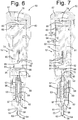
- Figs. 6,7 , 8 and 9 show different sectional views of the fuel valve 50.
- the fuel valve 50 has an elongated valve housing 52 with a rearmost end and a nozzle 54 at its front end.
- the nozzle 54 is a separate body that is attached to the front end of the valve housing 52.
- the rearmost end of the valve housing 52 is provided with a plurality of ports, including a control port 86, an actuation fluid port 78 and a gas leak detection port (not shown).
- the rearmost end is enlarged to form a head that protrudes from the cylinder cover when the fuel valve 50 is mounted in the cylinder cover.
- the fuel valves 50 are placed around the central exhaust valve 4, i.e. relatively close to the wall of the cylinder liner.
- the elongated valve housing 52 and the other components of the fuel injection valve 50, as well as the nozzle are in an embodiment made of steel, such as e.g. tool steel or stainless steel.
- the nozzle 54 is provided with nozzle holes that are connected to the interior of the nozzle 54 and the nozzle holes are arranged in different directions in order to distribute the fuel in the combustion chamber.
- the nozzle holes are directed away from the cylinder liner which is relatively near due to the location of the fuel valve 50 in the cylinder head.
- the nozzle holes are arranged in the tip 56 of the nozzle 54. Further, the nozzle holes are directed such that they are roughly in the same direction as the direction of the swirl of the scavenge air in the combustion chamber caused by the configuration of the scavenge ports (this swirl is a well-known feature of large two-stroke turbocharged internal combustion engines of the uniflow type).
- the nozzle 54 is connected to the front end of the valve housing 52 with a union nut 57 securing and surrounding a portion of the nozzle body 55, surrounding an intermediate section 53 and surrounding a distal portion of the elongated valve housing 52.
- the nozzle body 55 is provided with a longitudinal bore in which the valve needle 61 is received.
- the longitudinal bore has a diameter that is larger than the diameter of the valve needle 61 in the portion of the longitudinal bore closest to the tip 56.
- the space between the longitudinal bore and the valve needle 61 forms a fuel cavity 58.
- An intermediate section of the longitudinal bore has a small clearance with the valve needle 61.
- the portion of the longitudinal bore in the nozzle body 55 most distant from the tip 56 of the nozzle 54 has an enlarged diameter matching and an enlarged diameter portion of the valve needle 61.
- the enlarged diameter portion of the valve needle 61 forms a needle actuation piston 62 with a pressure surface of the needle actuation piston 62 facing a needle actuation chamber 88 in the nozzle 54.
- the needle actuation chamber 88 is fluidically connected to the control port 86 via a control conduit 87.
- the control port 86 is connected to a source of control oil Pc.
- the enlarged diameter section of the longitudinal bore is aligned with a spring chamber 96 in the intermediate section 53.
- the spring chamber 96 is aligned with a longitudinal bore in the elongated valve housing 52.
- the distal section of the longitudinal bore in the elongated valve housing 52 closest to the distal end of the elongated valve housing 52 has a diameter that corresponds to the diameter and the spring chamber 96.
- a helical wire spring 68 extends between the distal section of the longitudinal bore in the elongated valve housing 52 and the enlarged diameter section 62 of the valve needle 61.
- the valve needle 61 is resiliently biased towards its closed position by the pre-tensioned helical wire spring 68.
- the helical wire spring 68 is a helical wire spring that is received in a spring chamber 96 in the elongated fuel valve housing 52.
- the helical wire spring 68 biases the valve needle 61 towards the tip 56 of the nozzle 54, i.e. to its closed position.
- the, preferably conical, tip of the valve needle 61 abuts with a preferably conical valve seat 63 in the tip 56 of the interior of the nozzle 54 and closes the fluidic connection between the fuel cavity 58 and the nozzle holes.
- the fluidic connection between the fuel cavity 58 and the nozzle holes is established when the valve needle 61 is lifted, i.e. when the valve needle 61 is forced towards the proximate end of the fuel valve 50 against the bias of the helical wire spring 68.
- the valve needle 61 is lifted when the needle actuation chamber 88 is pressurized.
- a spring guide 69 extends concentrically in the spring chamber 96 for guiding the helical wire spring 68.
- the proximate end of the spring guide 69 is sealingly received in the longitudinal bore in the elongated valve housing 52.
- the axially displaceable valve needle 61 is slidably received with a small clearance in a longitudinal bore in the nozzle body 55, and lubrication between the axially displaceable valve needle 61 and the longitudinal bore is critical.
- pressurized sealing liquid is delivered to the small clearance between the longitudinal bore in the valve needle via a conduit (channel) 93.
- the channel 93 connects the small clearance between the valve needle 61 and the longitudinal bore to a sealing liquid inlet port 70, which in turn can be connected to the source of pressurized sealing liquid.
- the connection between the small clearance and the channel 93 includes a transverse bore 99 ( Fig. 8 ) in the valve needle 61 that connects to an axial bore 97 ( Fig.
- the channel 93 connects to the spring chamber 96 and supplies the spring chamber 96 with pressurized sealing liquid.
- the spring chamber 96 is connected via a bore to a sealing liquid outlet port 95.
- the sealing liquid prevents leakage of low flashpoint fuel through the small clearance between the valve needle 61 and the axial bore and provides cooling to the fuel valve 50.
- the sealing liquid which is preferably an oil, provides for lubrication between the valve needle 61 and the longitudinal bore.
- the elongated valve housing 52 is provided with a fuel inlet port 76 for connection to a source of pressurized low flashpoint liquid fuel, for example via the low flashpoint liquid fuel supply conduit 31.
- the fuel inlet port 76 connects to a pump chamber 82 in the valve housing 52 via a conduit 73 in a pump piston 80 and a one-way valve 89, preferably a spring loaded poppet valve.
- the one-way valve 89 (suction valve) is provided in the pump piston 80 at an inlet 71 of the conduits 73.
- the one-way valve 89 is a spring loaded poppet valve that ensures that liquid low flashpoint fuel can flow from the fuel inlet port 76 via conduit 73 to the pump chamber 82, but not in the opposite direction.
- the fluidic connection between the conduit 73 in the pump piston 80 and the fuel inlet port 76 in the elongated valve housing 52 is established by a receded area 74 in the pump piston 80 that in axial direction overlaps with the bore in the elongated valve housing 52 that forms the fuel inlet port 76.
- the pump piston 80 is slidably and sealingly received in a first bore 81 in the elongated fuel valve housing 52 with a pump chamber 82 in the first bore 81 on one side of the pump piston 80.
- An actuation piston 83 is slidably and sealingly received in a second bore 84 in the valve housing 52 with an actuation chamber 85 in the second bore 84 on one side of the actuation piston 83.
- the pump piston 80 is connected to the actuation piston 83 to move in unison therewith, i.e. the pump piston 80 and the actuation piston 83 can slide in unison with their respective bores 81,84.
- the pump piston 80 and the actuation piston 83 are formed as a single body. However, it is noted that the pump piston 80 and the actuation piston 83 can be separate interconnected bodies.
- the actuation chamber 85 is fluidically connected to an actuation fluid port 78.
- the first control valve 41 controls the flow pressurized actuation liquid to and from the actuation fluid port 78 and thereby to and from to the actuation chamber 85.
- the electronic control unit 25 commands the first control valve 41 to allow high pressure actuation liquid into the actuation chamber 85.
- the actuation piston 83 and pump piston 80 combination is in the position shown in Fig. 6 .
- the pressurized actuation liquid in the actuation chamber 85 acts on the actuation piston 83, thereby creating a force that urges the pump piston 80 into the pump chamber 82. Thereby, the pressure of the low flashpoint liquid fuel in the pump chamber 82 increases.
- the diameter of the actuation piston 83 is larger than the diameter of the pump piston 80 and thus the pressure in the pump chamber 82 will be correspondingly higher than the pressure in the actuation chamber 85, and the combination of the actuation piston 83 and pump piston 80 acts as a pressure booster.
- One or more fuel channels 79 fluidically connect the pump chamber 82 to the fuel cavity 58 and thereby to the valve seat that is located at the bottom of the fuel cavity 58.
- a one-way valve 90 is placed between the fuel channels 79 and the pump chamber 82.
- the outlet 66 of the pump chamber 82 is connected to the inlet of the one-way valve 90.
- the one-way valve 90 comprises a valve member slidably received in an axial bore in the elongated valve housing 52 and the valve member is resiliently biased towards its seat, i.e. towards its closed position and prevents backflow of fuel from the fuel channels 79 into the pump chamber 82.
- the pressurized fluid in the actuation chamber 85 will cause the actuation piston 83 and the pump piston 80 to move downwards (downwards as in Figs. 6 to 9 ) as shown in Fig. 7 .
- the pressure in the pump chamber 82 will after a short compression phase be the product of the ratio between the effective pressure area of the pump piston 80 and the effective pressure area of the actuation piston 83 and the pressure in the actuation chamber 85.
- the pressure in the actuation chamber 85 will be substantially equal to the pressure of the source of high pressure fluid.
- an effective pressure surface ratio of e.g. 2,5:1 and a supply pressure of the hydraulic system of e.g. 225 to 300 bar the pressure in the fuel in pump chamber will be approximately 500 bar at the end of the compression phase.
- the combination of the actuation piston 83 and pump piston 80 acts as a pressure booster.
- the electronic control unit 25 pressurizes the actuation chamber 85 before the start of the fuel injection by a lead time sufficient to ensure that the pressure in the pump chamber 82 has reached the required injection pressure of e.g. 500 bar.
- the electronic control unit 25 determines when the valve needle 61 needs to lift and thus when the fuel injection commences.
- the valve needle 61 is configured to move in the direction away from the nozzle 54 to obtain lift, and towards the nozzle 54 to reduce lift.
- the valve needle 61 gets lift when the needle actuation chamber 88 is pressurized.
- the electronic control unit 25 instructs the second control valve 45 to connect the fuel valve actuation signal conduit 48 to the source of high pressure hydraulic fluid at the moment in the engine cycle when the fuel injection has to commence.
- the fuel valve actuation signal conduit 48 is connected to the control port 86 and the high pressure fluid reaches the needle actuation chamber 88 via control conduit 87.
- the valve needle 61 When the valve needle 61 has lift from its seat it allows flow of low flashpoint liquid fuel from the fuel cavity 58 through the nozzle holes into the combustion chamber.
- the electronic control unit 25 ends an injection event by instructing the second control valve 45 to connect the needle actuation chamber 88 to tank and thereupon the valve needle 61 returns to its seat and prevents further injection of fuel. Simultaneously or shortly thereafter, the electronic control unit 25 instructs the first control valve 41 to connect the actuation chamber 85 to tank.
- the pump chamber 82 is connected to the pressurized source of low flashpoint fuel 30 and the supply pressure of the low flashpoint liquid fuel that flows in via the one-way valve 89 urges the actuation piston 83 into the actuation chamber 85 until it has reached the position that is shown in Fig. 6 with the pump chamber 82 completely filled with low flashpoint liquid fuel so that the fuel valve 50 is ready for the next injection event.
- Fig. 8 shows the position of the pump piston 80 and the actuation position 83 near the end of an injection event with a major part of the pump chamber 80 depleted from low flashpoint fuel.
- An injection event of the low flashpoint fuel is controlled by the electronic control unit 25 by the timing and the duration of lift of the valve needle 61.
- the electronic control unit can also control the injection event by regulating the pressure supplied to the actuation chamber 85 in order to perform rate shaping.
- the fuel valve 50 is provided with a sealing liquid inlet port 70 for connection to a source of pressurized sealing liquid Ps.
- the pressure of the source of sealing liquid is at least as high as the maximum pressure in the pump chamber 82 during an injection event. In another embodiment the pressure of the source of sealing liquid is at least as high as the supply pressure of the low flashpoint fuel.
- the sealing liquid is provided to the small clearance between the longitudinal bore and the valve needle 61 via transverse bore 99 and needs only to seal against the supply pressure of the fuel since the fuel inlet port 76 is connected to a low-pressure fuel conduit 98 that extends from the fuel inlet port 76 through the elongated valve housing 52, through the intermediate section 53 into the nozzle body 55 and to the longitudinal bore in which the valve needle 61 is slidably received.
- the position at which the low-pressure fuel conduit 98 connects to the longitudinal bore is axially between the position where the fuel channels 79 connect to the longitudinal bore and the position where the transverse bore 99 connects to the longitudinal bore.
- Each of the fuel valves 50 is connected to a source of pressured ignition liquid Pi (also referred to as pilot oil).
- the ignition liquid is a liquid with suitable properties for initiating the ignition of the main fuel.
- Fuel oil such as e.g. marine diesel, is an example of a suitable ignition liquid.
- other liquids with good ignition qualities such as bio diesel, lubricating oil, heavy fuel oil or dimethyl ether (DME) can also be used.
- the valve housing 52 is provided with an ignition liquid inlet port 92 for connection to the source of pressurized ignition liquid Pi.
- the valve housing 52 is provided with an ignition liquid bore 94 extending from an ignition liquid inlet port 92 to the clearance 91 between the pump piston 80 and the first bore 81 for sealing the pump piston 80 in the first bore 81 in order to prevent the high-pressure fuel in the pump chamber 82 from leaking into the space under the actuation piston 83.
- the pump piston 80 Since the pump piston 80 is slidably received in the first bore 81 with a preferably calibrated clearance 91 between the pump piston 80 and the first bore 81 and since the clearance 91 opens to the pump chamber 82, a small quantity of ignition liquid will reach the pump chamber 82 for each injection event via the clearance 91 between the pump piston 80 and the first bore 81.
- the amount of ignition liquid that will reach the pump chamber for each injection event will depend on the pressure of the source of ignition liquid Pi, and on the dimensions of the clearance 91.
- the ignition liquid that reaches the pump chamber will mix with the fuel and will be delivered to the nozzle 54 and injected with the fuel into the combustion chamber.
- the small quantity of ignition liquid that is mixed with the main fuel assists in reliably igniting the main fuel in the combustion chamber.
- the quantity (for each injection event) of ignition liquid that is required for reliably igniting the main fuel in the combustion chamber will depend on the number of circumstances, such as e.g. the type of main fuel, the type of ignition liquid, the constructional details of the combustion chamber, the constructional details of the nozzle 54, the timing of the fuel injection, the compression pressure, the temperature of the scavenging air and the ratio of recirculated exhaust gas.
- this is not an exhaustive list of aspects that influence the ignition of the main fuel. Through simple trial and error, the skilled person is able to determine the required amount.
- the pressure of the source of ignition liquid is adjusted in order to adjust the quantity of ignition liquid that is delivered to the pump chamber 82, i.e. the pressure of the source of ignition liquid Pi is increased when the quantity of ignition liquid needs to be increased and the pressure of the source of the ignition liquid is reduced when the quantity of ignition liquid needs to be reduced.
- the pressure of the source of the ignition liquid Pi is always higher than the pressure at which the main fuel is delivered to the fuel inlet port 76.
- the pressure at which the ignition liquid Pi is delivered can be higher than the maximum pressure in the pump chamber 82, but this is generally not necessary since it is acceptable that some main fuel enters the clearance 91 between the pump piston 80 and the first bore 81 during the pump stroke.
- Fig. 10 shows an alternative type of nozzle 54 for use with the fuel valve 50 described above with reference to Figs. 5 to 9 .
- the nozzle 54 is of a so-called slider type in which the valve seat 63 is arranged at a distance from the tip 56 of the nozzle 54 and the tip 56 of the nozzle is in this embodiment closed, i.e. the tip 56 does not have any nozzle holes. Instead, the nozzle holes are arranged along the length of the nozzle starting at a position close to the tip 56 going upwards (upward as in the orientation of Fig. 10 ).
- the valve needle 61 is provided with a conical section that cooperates with the valve seat 63 and a slider section that extends from the conical section of the valve needle 61 towards the tip of the valve needle 61.
- This type of nozzle with a closed tip and a slider of the valve needle 61 extending inside the nozzle 54 towards the tip 56 is well known in the art and will therefore not be described in any greater detail.
- the pressure of the source of pressurized ignition liquid Pi is electronically controllable, and the electronic control unit 25 is configured to control the pressure of said source of pressurized ignition liquid Pi.
- the amount of ignition liquid delivered through the clearance 91 to the pump chamber 82 can be controlled by the electronic control unit by adjusting the pressure of the source of pressurized ignition liquid Pi.
- the engine is provided with a non-low flashpoint fuel supply system (not shown), and the cylinders are provided with two or more fuel valves 51 for injecting said non-low flashpoint fuel into said cylinders.
- the concept of the invention is not restricted to high compressibility fuels and neither to low flash point fuels.
Landscapes
- Engineering & Computer Science (AREA)
- Chemical & Material Sciences (AREA)
- Combustion & Propulsion (AREA)
- Mechanical Engineering (AREA)
- General Engineering & Computer Science (AREA)
- Oil, Petroleum & Natural Gas (AREA)
- Chemical Kinetics & Catalysis (AREA)
- General Chemical & Material Sciences (AREA)
- Fuel-Injection Apparatus (AREA)
- Output Control And Ontrol Of Special Type Engine (AREA)
Abstract
Description
- The disclosure relates to large slow-running two-stroke compression-ignited internal combustion crosshead engines with a fuel injection system for injecting a low flashpoint fuel into the combustion chambers.
- Large two-stroke uniflow turbocharged compression-ignited internal combustion crosshead engines are typically used in propulsion systems of large ships or as prime mover in power plants. The sheer size, weight and power output renders them completely different from common combustion engines and places large two-stroke turbocharged compression-ignited internal combustion engines in a class for themselves.
- Large two-stroke compression-ignited internal combustion engines are conventionally operated with a liquid fuel such as e.g. fuel oil or heavy fuel oil but increased focus on environmental aspects has led to the development towards using alternative types of fuel such as gas, methanol, coal slurry, petroleum coke and the like. One group of fuels that is in increasing demand are low flashpoint fuels.
- Many low flashpoint fuels, such as e.g. methanol, ethanol, LPG, DME or biofuel, naphtha, gasoline (petrol), crude gasoline and crude oil are relatively clean fuels that result in significantly lower levels of sulfurous components, NOx and CO2 in the exhaust gas when used as fuel for a large low-speed uniflow turbocharged two-stroke internal combustion engine when compared with e.g. using heavy fuel oil as fuel.
- However, there are problems associated with using low flashpoint fuels in a large low-speed uniflow turbocharged two-stroke internal combustion engine. One of those problems is the low flashpoint, which causes significant problems if low flashpoint fuel leaks into one of the other systems of the engine and mixes with another fluid, such as e.g. the lubrication oil system. Low flashpoint fuel is inherently flammable, and vapors thereof can easily form explosive mixtures. Thus, should low flashpoint find its way into another system of the engine it is necessary to stop the engine operation for safety reasons and to clean or replace all of the liquid in such a system, a costly and cumbersome affair for the operator of the engine.
- It is known in the art to provide large two-stroke compression ignited internal combustion engines with a common rail type system that stores and distributes the low flashpoint fuel at the required injection pressure of typically several hundred bar (depending on the type of low flashpoint fuel and the engine requirements), with accumulators close to the fuel valves. The common rail type system is connected to two or three fuel injection valves in the cylinder cover of each cylinder. The fuel injection valves are electronically controlled and fuel injection is timed by electronically (the signal originates in an electronic control unit but the actual signal to the fuel valve is typically a hydraulic signal, i.e. electronic signal is converted to a hydraulic signal between the electronic control unit and the fuel valve) controlling the time (relative to the engine cycle) at which the fuel injection valve is opened.
- The known common rail type gaseous fuel supply systems for large two-stroke compression-ignited internal combustion engines have disadvantages when operating on LPG or any other similar low flashpoint fuel with a relatively high compressibility. The injection pressure for LPG needs to be as high as 600 bar, which means that the common rail system including all valves, accumulators, pipes, etc., needs to be laid out for this high pressure. Furthermore, the safety concept with the window valves is not well suited for dense gas like LPG, since firstly the gas channels between window valve and fuel valve need to have a very small volume and secondly, monitoring of the gas channel pressure necessary to ensure detection of leakages is made very difficult due to high frequency oscillation excited from closing of the window valve.
- It is also known in the art to use booster pumps and fuel pressure controlled fuel valves for injecting liquid gas, such as e.g. LPG. This concept has the problem associated therewith that the compressibility of LPG is rather large and dependent on pressure, temperature and gas composition. Hence, the delay between the actuation of the pressure booster and the actual gas injection is dependent on those parameters, which will make engine control, i.e. injection amount and particularly injection timing, very difficult. This is a significant problem, since injection timing is critical in compression-ignited engines.
-
EP3252291 discloses a fuel supply system according to the preamble ofclaim 1 that allows precise timing of the injection of the low flashpoint (and more compressible compared to fuel) fuel, using a pressure booster. - However, many of the low flashpoint fuels do not have good ignition properties resulting in an unreliable ignition if no ignition liquid is injected into the combustion chamber just before or together with the low flashpoint fuel.
- There is therefore a need to provide a fuel supply system for LPG and similar low flashpoint fuels that is safe, inexpensive, provides accurate control of the timing of the fuel admission into the cylinders and provides reliable ignition.
- It is known to use separate valves for injecting the ignition liquid into the combustion chamber. However, engines that operate on low flashpoint fuels are typically dual fuel engines that can also run on conventional fuel such as fuel oil or heavy fuel oil and the cylinder cover of the cylinders is provided with two or three fuel valves for the conventional fuel and two or three fuel valves for the low flashpoint fuel. Thus, with 4 to 6 fuel valves already present the cylinder cover is already crowded without additional valves for injecting the ignition liquid. Further, the amount of ignition liquid that is injected is typically very small compared to the amount of low flashpoint fuel. A typical range for the quantity of ignition liquid fuel is between 1.5 and 5% percent by weight of the low flashpoint fuel. Accordingly, these valves for injecting the ignition liquid are much smaller than the fuel valves for injecting the low flashpoint fuel and such small valves are typically too fragile to last in the harsh environment.
- It is an object of the invention to provide a large two-stroke turbocharged compression-ignited internal combustion crosshead engine that overcomes or at least reduces the problem indicated above.
- The foregoing and other objects are achieved by the features of the independent claims. Further implementation forms are apparent from the dependent claims, the description and the figures.
- According to a first aspect there is provided a fuel valve for injecting low flashpoint liquid fuel into the combustion chamber of a large slow running two-stroke turbocharged compression-igniting internal combustion engine, the fuel valve comprising:
- an elongated valve housing with a rear end and a front end,
- a nozzle with a plurality of nozzle holes, the nozzle being disposed at the front end of the elongated valve housing,
- a fuel inlet port in the elongated valve housing for connection to a source of pressurized low flashpoint fuel,
- an actuation fluid port in the elongated valve housing for connection to a source of actuation fluid,
- an axially displaceable valve needle slidably received in a longitudinal bore in the fuel valve, the valve needle having a closed position and an open position, and the valve needle being biased towards the closed position,
- the valve needle allowing flow of fuel from the fuel cavity to the plurality of nozzle holes when the valve needle is in its open position and the valve needle preventing flow of fuel from the fuel cavity to the plurality of nozzle holes when the valve needle is in its closed position,
- a pump piston received in a first bore in the valve housing with a pump chamber in the first bore on one side of the pump piston,
- the pump piston is slidably received in the first bore with a clearance between the pump piston and the first bore,
- an actuation piston received in a second bore in the valve housing with an actuation chamber in the second bore on one side of the actuation piston, the pump piston being operably connected to the actuation piston
- the actuation chamber being fluidically connected to the actuation fluid port,
- the pump chamber having an outlet fluidically connected to the fuel cavity and an inlet fluidically connected to the fuel inlet port,
- a sealing liquid inlet port for connection to a source of pressurized sealing liquid,
- a sealing oil flow path connecting the sealing liquid inlet port to the longitudinal bore for sealing the valve needle in the longitudinal bore,
- an ignition liquid inlet port for connection to a source of pressurized ignition liquid,
- an ignition liquid conduit extending from the ignition liquid inlet port to the clearance for sealing the pump piston in the first bore and for delivering ignition liquid to the pump chamber.
- By providing an inlet port for ignition liquid and by providing a conduit that transports the ignition liquid to the first bore for sealing the pump piston in the first bore with an overpressure the ignition liquid will seal the pump piston and ignition liquid will reach the pump chamber since the clearance opens to the pump chamber. Thus, a small quantity of ignition liquid reaches the pump chamber and is mixed with the low flashpoint fuel. The small quantity of ignition liquid mixed with the flow flashpoint fuel is pumped to the nozzle and injected into the combustion chamber. The presence of the ignition liquid mixed with the low flashpoint fuel enhances reliable ignition.
- According to a first possible implementation of the first aspect the pump piston is sealed in the first bore by the ignition liquid delivered via the ignition liquid conduit to the clearance.
- According to a second possible implementation of the first aspect the clearance opens to the pump chamber and the ignition liquid is delivered to the pump chamber via the clearance.
- According to a third possible implementation of the first aspect the flow path comprises a conduit in the valve housing connected to the sealing liquid inlet port and/or a spring chamber of a spring that biases the valve needle to the valve seat and/or an axial bore in the valve needle and/or a transverse bore in the valve needle.
- According to a fourth possible implementation of the first aspect the sealing oil flow path connects the sealing liquid inlet port to the longitudinal bore at a first position along the length of the longitudinal bore for sealing the valve needle in the longitudinal bore.
- According to a fifth possible implementation of the first aspect the low-pressure conduit connects the low flashpoint fuel inlet port to the longitudinal bore at a second position along the length of the longitudinal bore, the second position being closer to the fuel cavity than the first position. The pressure in the low-pressure conduit is significantly lower than the injection pressure and thus, the connection to the low-pressure conduit "punctures" the high-pressure coming from the fuel cavity and thus, the sealing oil only needs to seal the clearance between the valve needle and the longitudinal bore against the lower fuel pressure in the low-pressure conduit.
- According to a sixth possible implementation of the first aspect the valve needle rests on a valve seat in the closed position and the valve needle has lift from the valve seat in the open position.
- According to a seventh possible implementation of the first aspect the nozzle has a nozzle body that is secured to the front of the elongated valve housing.
- According to an eighth possible implementation of the first aspect the valve seat is located in the tip of the nozzle.
- According to a ninth possible implementation of the first aspect the longitudinal bore is formed at least partially in the nozzle body.
- According to a tenth possible implementation of the first aspect the lift of the valve needle is controlled by the fuel pressure in the fuel cavity.
- According to an eleventh possible implementation of the first aspect the valve needle is operably connected to a needle actuation piston with a pressure surface of the needle actuation piston facing a needle actuation chamber in the fuel valve, the needle actuation chamber being fluidically connected to a control port in the fuel valve for connection to a controllable source of control fluid.
- According to a twelfth possible implementation of the first aspect the fuel valve is provided with a valve needle that controls the flow of fuel to nozzle holes of the nozzle of the fuel valve, the position of the valve needle preferably being controlled by a control signal and not by the fuel pressure.
- According to a thirteenth possible implementation of the first aspect the pump chamber has an inlet fluidically connected to the fuel inlet port via a first one-way valve.
- According to a fourteenth possible implementation of the first aspect the pump chamber having an outlet fluidically connected to the fuel cavity via a second one-way valve.
- According to a fifteenth possible implementation of the first aspect the effective pressure area of the pump piston is smaller than the effective pressure area of the actuation piston.
- According to a sixteenth possible implementation of the first aspect the nozzle is part of a nozzle body that is secured to the front of the elongated valve housing.
- According to a seventeenth possible implementation of the first aspect the inlet is located in the pump piston.
- According to an eighteenth possible implementation of the first aspect a first one-way valve is provided in the inlet, the first one-way valve being configured to allow flow of low flashpoint fuel through the inlet into the pump chamber and to prevent flow from the pump chamber into the inlet.
- According to a nineteenth possible implementation of the first aspect the outlet of the pump chamber is connected to the fuel cavity by one or more fuel channels.
- According to a twentieth possible implementation of the first aspect a second one-way valve is provided in the one or more fuel channels, the second one-way valve being configured to allow flow of low flashpoint fuel from the pump chamber to the fuel cavity and to prevent flow from the fuel cavity to the pump chamber.
- According to twenty-first possible implementation of the first aspect the pump piston is operably connected to the actuation piston to move in unison therewith.
- According to a second aspect, there is provided a large two-stroke turbocharged compression-ignited internal combustion crosshead engine comprising:
- a plurality of cylinders,
- two or more fuel valves according to the first aspect or any possible implementation thereof arranged in each cylinder, the fuel valves being connected to a source of pressurized ignition liquid Pi, to a source of pressurized sealing oil Ps and to a low flashpoint fuel supply system.
- According to a first possible implementation of the second aspect the pressure of the source of pressurized ignition liquid is electronically controllable, and the engine comprises an electronic control unit configured to control the pressure of the source of pressurized ignition liquid.
- According to a second possible implementation of the second aspect the engine is provided with a non-low flashpoint fuel supply system, and wherein the cylinders are provided with two or more fuel valves for injecting the non-low flashpoint fuel into the cylinders.
- These and other aspects of the invention will be apparent from the embodiments described below.
- In the following detailed portion of the present disclosure, the invention will be explained in more detail with reference to the example embodiments shown in the drawings, in which:
-
Fig. 1 is an elevated front view of a large two-stroke diesel engine according to an example embodiment. -
Fig. 2 is an elevated side view of the large two-stroke engine ofFig. 1 . -
Fig. 3 is a diagrammatic representation of the large two-stroke engine according toFig. 1 . -
Fig. 4a is a diagrammatic representation of the fuel injection system for injecting a low flashpoint fuel into the engine ofFigs. 1 and 2 . -
Fig 4b is a diagrammatic representation of an embodiment of a fuel valve for use in the engine ofFigs. 1 and 2 , showing the sources of liquid connected to the fuel valve. -
Fig. 5 is an elevated view of a fuel valve according to an embodiment. -
Figs. 6 to 9 are different sectional views of the fuel valve ofFig. 5 , -
Fig. 10 illustrates an alternative nozzle for the fuel valve ofFig. 5 . - In the following detailed description, an internal combustion engine will be described with reference to a large two-stroke low-speed uniflow turbocharged compression-ignited internal combustion engine with crossheads in the example embodiments, but it is understood that the internal combustion engine could be of another type, such as a two-stroke Otto, a four-stroke Otto or Diesel, with or without turbocharging, with or without exhaust gas recirculation.
-
Figs. 1, 2 and3 show a large low-speed turbocharged two-stroke diesel engine with acrankshaft 8 andcrossheads 9.Fig. 3 shows a diagrammatic representation of a large low-speed turbocharged two-stroke diesel engine with its intake and exhaust systems. In this example embodiment the engine has six cylinders in line. Large low-speed turbocharged two-stroke diesel engines have typically between four and fourteen cylinders in line, carried by acylinder frame 23 that is carried by anengine frame 11. The engine may e.g. be used as the main engine in a marine vessel or as a stationary engine for operating a generator in a power station. The total output of the engine may, for example, range from 1,000 to 110,000 kW. - The engine is in this example embodiment a compression-ignited engine of the two-stroke uniflow type with
scavenge ports 18 at the lower region of thecylinder liners 1 and acentral exhaust valve 4 at the top of thecylinder liners 1. The scavenge air is passed from thescavenge air receiver 2 to thescavenge ports 18 of theindividual cylinders 1. Apiston 10 in thecylinder liner 1 compresses the scavenge air. Fuel is injected throughfuel valves 50 in thecylinder cover 22. Combustion follows, and exhaust gas is generated. Thefuel valves 50 are suitable for injecting a low flashpoint fuel into the combustion chamber. In an embodiment the engine is additionally provided with fuel valves 51 that are suitable for injecting a conventional (non-low flashpoint fuel, such as e.g. fuel oil or heavy fuel oil) fuel into the combustion chamber. - When an
exhaust valve 4 is opened, the exhaust gas flows through an exhaust duct associated with thecylinders 1 into theexhaust gas receiver 3 and onwards through afirst exhaust conduit 19 to aturbine 6 of theturbocharger 5, from which the exhaust gas flows away through a second exhaust conduit via aneconomizer 20 to anoutlet 21 and into the atmosphere. Through a shaft, theturbine 6 drives acompressor 7 supplied with fresh air via anair inlet 12. Thecompressor 7 delivers pressurized scavenge air to ascavenge air conduit 13 leading to thescavenge air receiver 2. The scavenge air in thescavenge air conduit 13 passes anintercooler 14 for cooling the scavenge air. - The cooled scavenge air passes via an
auxiliary blower 16 driven by anelectric motor 17 that pressurizes the scavenge air flow when thecompressor 7 of theturbocharger 5 does not deliver sufficient pressure for thescavenge air receiver 2, i.e. in low or partial load conditions of the engine. At higher engine loads theturbocharger compressor 7 delivers sufficient compressed scavenge air and then theauxiliary blower 16 is bypassed via anon-return valve 15. The engine is operated with a low flashpoint fuel, such as e.g. LPG, methanol or naphtha and supplied by a low flashpointfuel supply system 30 in liquid or supercritical form at a substantially stable pressure and temperature. However, depending on the details of the low flashpoint fuel supply system and the type of gas supplied slight variations in temperature and pressure are unavoidable. Further, slight variations in the composition of the low flashpoint fuel can also occur. In an embodiment, the engine is a dual fuel engine and is also provided with a conventional fuel supply system (not shown) for supplying a non-low flashpoint fuel, such as e.g. fuel oil or heavy fuel oil. - The low flashpoint
fuel supply system 30 suppliesfuel injection valves 50 with low flashpoint fuel at relatively low supply pressure (e.g. 8 to 100 bar pressure) via asupply conduit 31. -
Fig. 4a is a diagram showing the fuel injection system that receives the low flashpoint fuel via thesupply conduit 31. The fuel injection system comprises apressure booster 40 for pressurizing the fuel to the injection pressure. Thepressure booster 40 is hydraulically actuated under control of afirst control valve 41. Thefuel valves 50 are hydraulically actuated under control of asecond control valve 45. - The diagram in
Fig. 4a shows the fuel injection system for asingle cylinder 1, with onepressure booster 40 and threefuel injection valves 50. Instead of three, there could also be twofuel valves 50 for eachcylinder 1. Eachcylinder 1 will require apressure booster 40 supplying two or threefuel valves 50. - The
pressure booster 40 comprises a large diameter plunger connected to a smaller diameter plunger to move in unison therewith. The large diameter plunger and the small diameter plunger are received in respective matching bores in the housing of thepressure booster 40. The large diameter plunger faces an actuation chamber that is supplied with high pressure hydraulic fluid or with tank under control of thefirst control valve 41. - The small diameter plunger faces a pump chamber that is connected to the
fuel supply conduit 31 via a one-way valve and to a high-pressurefuel supply line 35 for the delivery of high pressure fuel to thefuel valves 50. A one-way valve prevents backflow of fuel from the high-pressurefuel supply line 35 to the pump chamber. The pressure of the fuel in thesupply conduit 31 is sufficient to cause thepressure booster 40 to make a return stroke when the actuation chamber is connected to tank. A position sensor 34 senses the position of the large and small diameter plungers. - In the present embodiment the
first control valve 41 comprises a preferably proportional first hydraulically controlled three-way valve 42. The first three-way valve 42 is connected to the actuation chamber via anactuation conduit 44, to a source of high-pressure hydraulic fluid and to tank. The first three-way valve 42 is configured to connect the actuation chamber selectively to tank or to the source of high-pressure hydraulic fluid. Since the first hydraulically controlled three-way valve 42 is in an embodiment a proportional valve capable of assuming any intermediate position between connection to the source of high-pressure hydraulic fluid and tank. The position of the first three-way valve 42 is controlled by a first smaller two-way valve 43 and the position of the first smaller two-way valve 43 is electronically controlled. The first smaller two-way valve 43 is connected to anelectronic control unit 25 via afirst signal cable 26. In an embodiment, thefirst control valve 41 is under command of a separate electronic control unit that is mainly configured for maintaining safety and will deactivate the pressure booster when a safety issue, such as e.g. a gas leak, has been detected. Alternatively, the first control valve is connected to a source of high pressure hydraulic fluid that is controlled by an engine safety system. - The high-pressure
fuel supply line 35 is split up into three high-pressure fuel supply lines 35-1, 35-2, 35-3, i.e. one high-pressure fuel supply line for supplying eachfuel valve 50 with high-pressure low flashpoint fuel. In an embodiment with twofuel valves 50 per cylinder the high-pressurefuel supply line 35 will be split in two lines. - As shown in
Fig. 4b , eachfuel valve 50 is connected to a supply of pressurized sealing oil Ps via a sealingoil supply line 36 and with a sealing oil return line. The flow sealing oil through thefuel valve 50 is in an embodiment relatively large so that the sealing oil also acts as a cooling medium for thefuel valve 50. - Each
fuel valve 50 is connected to a fuel valveactuation signal conduit 48. The pressure in the fuel valveactuation signal conduit 48 is controlled by asecond control valve 45 that comprises in an embodiment a second hydraulically controlled proportional three-way valve 46 and a second smaller electronically controlled two-way valve 47. The second hydraulically controlled three-way valve 46 is preferably a proportional valve and is configured to connect theactuation signal conduit 48 to a source of high-pressure hydraulic fluid or to tank. Since the second hydraulically controlled three-way valve 46 is in an embodiment a proportional valve it is capable of assuming any intermediate position between connection to the source of high-pressure hydraulic fluid and tank. The position of the second three-way valve 46 is controlled by a second smaller two-way valve 47 and the position of the second smaller two-way valve 47 is electronically controlled. The second smaller two-way valve 47 is connected to theelectronic control unit 25 via athird signal cable 28. Theelectronic control unit 25 is informed of the position of the second three-way valve 46 via asecond signal cable 27. - The
electronic control unit 25 is in receipt of signals from various sensors via signal cables that are illustrated inFig. 4a as interrupted lines. The signals from the various sensors include e.g. scavenging pressure, temperature, exhaust pressure, temperature, crank angle and speed, although it is noted that this list is not exhaustive and will depend on the construction of the engine, for example whether it includes exhaust gas recirculation or not, whether it includes a turbocharger or not, etc. Theelectronic control unit 25 controls thefuel injection valves 50 i.e. the electronic control unit determines when the fuel valve 50is open and determines the duration of the opening time. Theelectronic control unit 25 also controls the operation of thepressure booster 40. - The timing of the fuel injection highly affects the combustion pressure in the large two-stroke turbocharged diesel engine (compression-ignited engine). The timing of the opening of the
fuel valves 50 relative to the crankshaft angle or relative to the engine cycle largely determines the combustion pressure. The duration of the opening of thefuel valves 50 determines the amount of fuel admitted to thecylinders 1, with increasing duration leading to increasing amount of fuel being admitted to thecylinders 1. - The
electronic control unit 25 is configured to control the timing of the opening of the fuel valves by an electronic signal to thesecond control valve 45 via thethird signal cable 28. Upon receipt of the signal the electronic control valve switches position and connects theactuation signal conduit 48 to the source of high-pressure hydraulic fluid. The high pressure in theactuation signal conduit 48 opens thefuel valve 50. - In the embodiment above the
pressure booster 40 and thefuel valve 50 are separate physical units. In an embodiment thepressure booster 40 is an integral part of thefuel valve 50. - An embodiment of a
fuel valve 50 with an integrated pressure booster is shown inFigs. 5 to 9 . -
Fig. 5 is a perspective view of thefuel valve 50 with itselongated valve housing 52, anozzle 54 secured to the front end of theelongated valve housing 52. Thenozzle 54 is provided with a plurality of nozzle holes 56 for creating jets of fuel into the combustion chamber. Thenozzle 54 is removably secured to theelongated valve housing 52, so that it can be easily replaced if thenozzle 54 should fail or be worn out. -
Figs. 6,7 ,8 and 9 show different sectional views of thefuel valve 50. Thefuel valve 50 has an elongatedvalve housing 52 with a rearmost end and anozzle 54 at its front end. Thenozzle 54 is a separate body that is attached to the front end of thevalve housing 52. The rearmost end of thevalve housing 52 is provided with a plurality of ports, including acontrol port 86, anactuation fluid port 78 and a gas leak detection port (not shown). The rearmost end is enlarged to form a head that protrudes from the cylinder cover when thefuel valve 50 is mounted in the cylinder cover. In the present embodiment, thefuel valves 50 are placed around thecentral exhaust valve 4, i.e. relatively close to the wall of the cylinder liner. Theelongated valve housing 52 and the other components of thefuel injection valve 50, as well as the nozzle, are in an embodiment made of steel, such as e.g. tool steel or stainless steel. - The
nozzle 54 is provided with nozzle holes that are connected to the interior of thenozzle 54 and the nozzle holes are arranged in different directions in order to distribute the fuel in the combustion chamber. The nozzle holes are directed away from the cylinder liner which is relatively near due to the location of thefuel valve 50 in the cylinder head. The nozzle holes are arranged in thetip 56 of thenozzle 54. Further, the nozzle holes are directed such that they are roughly in the same direction as the direction of the swirl of the scavenge air in the combustion chamber caused by the configuration of the scavenge ports (this swirl is a well-known feature of large two-stroke turbocharged internal combustion engines of the uniflow type). - The
nozzle 54 is connected to the front end of thevalve housing 52 with aunion nut 57 securing and surrounding a portion of thenozzle body 55, surrounding anintermediate section 53 and surrounding a distal portion of theelongated valve housing 52. Thenozzle body 55 is provided with a longitudinal bore in which thevalve needle 61 is received. The longitudinal bore has a diameter that is larger than the diameter of thevalve needle 61 in the portion of the longitudinal bore closest to thetip 56. The space between the longitudinal bore and thevalve needle 61 forms afuel cavity 58. An intermediate section of the longitudinal bore has a small clearance with thevalve needle 61. The portion of the longitudinal bore in thenozzle body 55 most distant from thetip 56 of thenozzle 54 has an enlarged diameter matching and an enlarged diameter portion of thevalve needle 61. The enlarged diameter portion of thevalve needle 61 forms aneedle actuation piston 62 with a pressure surface of theneedle actuation piston 62 facing aneedle actuation chamber 88 in thenozzle 54. Theneedle actuation chamber 88 is fluidically connected to thecontrol port 86 via acontrol conduit 87. Thecontrol port 86 is connected to a source of control oil Pc. - The enlarged diameter section of the longitudinal bore is aligned with a
spring chamber 96 in theintermediate section 53. Thespring chamber 96 is aligned with a longitudinal bore in theelongated valve housing 52. The distal section of the longitudinal bore in theelongated valve housing 52 closest to the distal end of theelongated valve housing 52 has a diameter that corresponds to the diameter and thespring chamber 96. Ahelical wire spring 68 extends between the distal section of the longitudinal bore in theelongated valve housing 52 and theenlarged diameter section 62 of thevalve needle 61. Thevalve needle 61 is resiliently biased towards its closed position by the pre-tensionedhelical wire spring 68. Thehelical wire spring 68 is a helical wire spring that is received in aspring chamber 96 in the elongatedfuel valve housing 52. Thehelical wire spring 68 biases thevalve needle 61 towards thetip 56 of thenozzle 54, i.e. to its closed position. In the closed position of thevalve needle 61 the, preferably conical, tip of thevalve needle 61 abuts with a preferablyconical valve seat 63 in thetip 56 of the interior of thenozzle 54 and closes the fluidic connection between thefuel cavity 58 and the nozzle holes. The fluidic connection between thefuel cavity 58 and the nozzle holes is established when thevalve needle 61 is lifted, i.e. when thevalve needle 61 is forced towards the proximate end of thefuel valve 50 against the bias of thehelical wire spring 68. Thevalve needle 61 is lifted when theneedle actuation chamber 88 is pressurized. - A
spring guide 69 extends concentrically in thespring chamber 96 for guiding thehelical wire spring 68. The proximate end of thespring guide 69 is sealingly received in the longitudinal bore in theelongated valve housing 52. - The axially
displaceable valve needle 61 is slidably received with a small clearance in a longitudinal bore in thenozzle body 55, and lubrication between the axiallydisplaceable valve needle 61 and the longitudinal bore is critical. Hereto, pressurized sealing liquid is delivered to the small clearance between the longitudinal bore in the valve needle via a conduit (channel) 93. Thechannel 93 connects the small clearance between thevalve needle 61 and the longitudinal bore to a sealingliquid inlet port 70, which in turn can be connected to the source of pressurized sealing liquid. The connection between the small clearance and thechannel 93 includes a transverse bore 99 (Fig. 8 ) in thevalve needle 61 that connects to an axial bore 97 (Fig. 8 ) in thevalve needle 61 that extends all the way through the enlarged diameter section that forms theneedle actuation piston 62 to thespring chamber 96. Thechannel 93 connects to thespring chamber 96 and supplies thespring chamber 96 with pressurized sealing liquid. In order to allow a substantial flow of sealing liquid through thespring chamber 96 so that the sealing liquid may act as a cooling medium thespring chamber 96 is connected via a bore to a sealingliquid outlet port 95. The sealing liquid prevents leakage of low flashpoint fuel through the small clearance between thevalve needle 61 and the axial bore and provides cooling to thefuel valve 50. Further, the sealing liquid, which is preferably an oil, provides for lubrication between thevalve needle 61 and the longitudinal bore. - The
elongated valve housing 52 is provided with afuel inlet port 76 for connection to a source of pressurized low flashpoint liquid fuel, for example via the low flashpoint liquidfuel supply conduit 31. Thefuel inlet port 76 connects to apump chamber 82 in thevalve housing 52 via aconduit 73 in apump piston 80 and a one-way valve 89, preferably a spring loaded poppet valve. The one-way valve 89 (suction valve) is provided in thepump piston 80 at aninlet 71 of theconduits 73. The one-way valve 89 is a spring loaded poppet valve that ensures that liquid low flashpoint fuel can flow from thefuel inlet port 76 viaconduit 73 to thepump chamber 82, but not in the opposite direction. The fluidic connection between theconduit 73 in thepump piston 80 and thefuel inlet port 76 in theelongated valve housing 52 is established by a recededarea 74 in thepump piston 80 that in axial direction overlaps with the bore in theelongated valve housing 52 that forms thefuel inlet port 76. - The
pump piston 80 is slidably and sealingly received in afirst bore 81 in the elongatedfuel valve housing 52 with apump chamber 82 in thefirst bore 81 on one side of thepump piston 80. Anactuation piston 83 is slidably and sealingly received in asecond bore 84 in thevalve housing 52 with anactuation chamber 85 in thesecond bore 84 on one side of theactuation piston 83. Thepump piston 80 is connected to theactuation piston 83 to move in unison therewith, i.e. thepump piston 80 and theactuation piston 83 can slide in unison with theirrespective bores pump piston 80 and theactuation piston 83 are formed as a single body. However, it is noted that thepump piston 80 and theactuation piston 83 can be separate interconnected bodies. - The
actuation chamber 85 is fluidically connected to anactuation fluid port 78. Thefirst control valve 41 controls the flow pressurized actuation liquid to and from theactuation fluid port 78 and thereby to and from to theactuation chamber 85. - A lead time before the start of injection event, the
electronic control unit 25 commands thefirst control valve 41 to allow high pressure actuation liquid into theactuation chamber 85. At this moment theactuation piston 83 andpump piston 80 combination is in the position shown inFig. 6 . The pressurized actuation liquid in theactuation chamber 85 acts on theactuation piston 83, thereby creating a force that urges thepump piston 80 into thepump chamber 82. Thereby, the pressure of the low flashpoint liquid fuel in thepump chamber 82 increases. In an embodiment the diameter of theactuation piston 83 is larger than the diameter of thepump piston 80 and thus the pressure in thepump chamber 82 will be correspondingly higher than the pressure in theactuation chamber 85, and the combination of theactuation piston 83 andpump piston 80 acts as a pressure booster. - One or
more fuel channels 79 fluidically connect thepump chamber 82 to thefuel cavity 58 and thereby to the valve seat that is located at the bottom of thefuel cavity 58. A one-way valve 90 is placed between thefuel channels 79 and thepump chamber 82. Theoutlet 66 of thepump chamber 82 is connected to the inlet of the one-way valve 90. The one-way valve 90 comprises a valve member slidably received in an axial bore in theelongated valve housing 52 and the valve member is resiliently biased towards its seat, i.e. towards its closed position and prevents backflow of fuel from thefuel channels 79 into thepump chamber 82. - The pressurized fluid in the
actuation chamber 85 will cause theactuation piston 83 and thepump piston 80 to move downwards (downwards as inFigs. 6 to 9 ) as shown inFig. 7 . The pressure in thepump chamber 82 will after a short compression phase be the product of the ratio between the effective pressure area of thepump piston 80 and the effective pressure area of theactuation piston 83 and the pressure in theactuation chamber 85. At this moment the pressure in theactuation chamber 85 will be substantially equal to the pressure of the source of high pressure fluid. With an effective pressure surface ratio of e.g. 2,5:1 and a supply pressure of the hydraulic system of e.g. 225 to 300 bar, the pressure in the fuel in pump chamber will be approximately 500 bar at the end of the compression phase. Thus, the combination of theactuation piston 83 andpump piston 80 acts as a pressure booster. - The
electronic control unit 25 pressurizes theactuation chamber 85 before the start of the fuel injection by a lead time sufficient to ensure that the pressure in thepump chamber 82 has reached the required injection pressure of e.g. 500 bar. Theelectronic control unit 25 determines when thevalve needle 61 needs to lift and thus when the fuel injection commences. Thevalve needle 61 is configured to move in the direction away from thenozzle 54 to obtain lift, and towards thenozzle 54 to reduce lift. Thevalve needle 61 gets lift when theneedle actuation chamber 88 is pressurized. Theelectronic control unit 25 instructs thesecond control valve 45 to connect the fuel valveactuation signal conduit 48 to the source of high pressure hydraulic fluid at the moment in the engine cycle when the fuel injection has to commence. The fuel valveactuation signal conduit 48 is connected to thecontrol port 86 and the high pressure fluid reaches theneedle actuation chamber 88 viacontrol conduit 87. When thevalve needle 61 has lift from its seat it allows flow of low flashpoint liquid fuel from thefuel cavity 58 through the nozzle holes into the combustion chamber. - The
electronic control unit 25 ends an injection event by instructing thesecond control valve 45 to connect theneedle actuation chamber 88 to tank and thereupon thevalve needle 61 returns to its seat and prevents further injection of fuel. Simultaneously or shortly thereafter, theelectronic control unit 25 instructs thefirst control valve 41 to connect theactuation chamber 85 to tank. Thepump chamber 82 is connected to the pressurized source oflow flashpoint fuel 30 and the supply pressure of the low flashpoint liquid fuel that flows in via the one-way valve 89 urges theactuation piston 83 into theactuation chamber 85 until it has reached the position that is shown inFig. 6 with thepump chamber 82 completely filled with low flashpoint liquid fuel so that thefuel valve 50 is ready for the next injection event.Fig. 8 shows the position of thepump piston 80 and theactuation position 83 near the end of an injection event with a major part of thepump chamber 80 depleted from low flashpoint fuel. - An injection event of the low flashpoint fuel is controlled by the
electronic control unit 25 by the timing and the duration of lift of thevalve needle 61. The electronic control unit can also control the injection event by regulating the pressure supplied to theactuation chamber 85 in order to perform rate shaping. - The
fuel valve 50 is provided with a sealingliquid inlet port 70 for connection to a source of pressurized sealing liquid Ps. In an embodiment, the pressure of the source of sealing liquid is at least as high as the maximum pressure in thepump chamber 82 during an injection event. In another embodiment the pressure of the source of sealing liquid is at least as high as the supply pressure of the low flashpoint fuel. - The sealing liquid is provided to the small clearance between the longitudinal bore and the
valve needle 61 viatransverse bore 99 and needs only to seal against the supply pressure of the fuel since thefuel inlet port 76 is connected to a low-pressure fuel conduit 98 that extends from thefuel inlet port 76 through theelongated valve housing 52, through theintermediate section 53 into thenozzle body 55 and to the longitudinal bore in which thevalve needle 61 is slidably received. The position at which the low-pressure fuel conduit 98 connects to the longitudinal bore is axially between the position where thefuel channels 79 connect to the longitudinal bore and the position where thetransverse bore 99 connects to the longitudinal bore. Thus, any low flashpoint fuel leaking upwards (upward as inFigs. 6 to 9 )) through the small clearance between the longitudinal bore and thevalve needle 61 from the highpressure fuel cavity 58 during an injection event will have its pressure reduced to the much lower fuel feed pressure when it reaches the position where the low-pressure fuel conduit 98 connects to the longitudinal bore. Thus, the low-pressure in the low-pressure fuel conduit 98 "punctures" the pressure of the fuel in the small clearance between thevalve needle 61 and the longitudinal bore and thus, the sealing liquid from the transverse bore 99 needs only to seal against the feed pressure of the low flashpoint fuel and not against the injection pressure. Thus, the pressure of the sealing oil needs only to be marginally higher than the feed pressure of the low flashpoint fuel and does not need to be as high or higher than the injection pressure of the fuel. - Each of the
fuel valves 50 is connected to a source of pressured ignition liquid Pi (also referred to as pilot oil). The ignition liquid is a liquid with suitable properties for initiating the ignition of the main fuel. Fuel oil, such as e.g. marine diesel, is an example of a suitable ignition liquid. However other liquids with good ignition qualities, such as bio diesel, lubricating oil, heavy fuel oil or dimethyl ether (DME) can also be used. - The
valve housing 52 is provided with an ignitionliquid inlet port 92 for connection to the source of pressurized ignition liquid Pi. Thevalve housing 52 is provided with an ignition liquid bore 94 extending from an ignitionliquid inlet port 92 to theclearance 91 between thepump piston 80 and thefirst bore 81 for sealing thepump piston 80 in thefirst bore 81 in order to prevent the high-pressure fuel in thepump chamber 82 from leaking into the space under theactuation piston 83. Since thepump piston 80 is slidably received in thefirst bore 81 with a preferably calibratedclearance 91 between thepump piston 80 and thefirst bore 81 and since theclearance 91 opens to thepump chamber 82, a small quantity of ignition liquid will reach thepump chamber 82 for each injection event via theclearance 91 between thepump piston 80 and thefirst bore 81. The amount of ignition liquid that will reach the pump chamber for each injection event will depend on the pressure of the source of ignition liquid Pi, and on the dimensions of theclearance 91. The ignition liquid that reaches the pump chamber will mix with the fuel and will be delivered to thenozzle 54 and injected with the fuel into the combustion chamber. The small quantity of ignition liquid that is mixed with the main fuel assists in reliably igniting the main fuel in the combustion chamber. - The quantity (for each injection event) of ignition liquid that is required for reliably igniting the main fuel in the combustion chamber will depend on the number of circumstances, such as e.g. the type of main fuel, the type of ignition liquid, the constructional details of the combustion chamber, the constructional details of the
nozzle 54, the timing of the fuel injection, the compression pressure, the temperature of the scavenging air and the ratio of recirculated exhaust gas. However, this is not an exhaustive list of aspects that influence the ignition of the main fuel. Through simple trial and error, the skilled person is able to determine the required amount. - In an embodiment, the pressure of the source of ignition liquid is adjusted in order to adjust the quantity of ignition liquid that is delivered to the
pump chamber 82, i.e. the pressure of the source of ignition liquid Pi is increased when the quantity of ignition liquid needs to be increased and the pressure of the source of the ignition liquid is reduced when the quantity of ignition liquid needs to be reduced. - The pressure of the source of the ignition liquid Pi is always higher than the pressure at which the main fuel is delivered to the
fuel inlet port 76. The pressure at which the ignition liquid Pi is delivered can be higher than the maximum pressure in thepump chamber 82, but this is generally not necessary since it is acceptable that some main fuel enters theclearance 91 between thepump piston 80 and thefirst bore 81 during the pump stroke. -
Fig. 10 shows an alternative type ofnozzle 54 for use with thefuel valve 50 described above with reference toFigs. 5 to 9 . In this embodiment thenozzle 54 is of a so-called slider type in which thevalve seat 63 is arranged at a distance from thetip 56 of thenozzle 54 and thetip 56 of the nozzle is in this embodiment closed, i.e. thetip 56 does not have any nozzle holes. Instead, the nozzle holes are arranged along the length of the nozzle starting at a position close to thetip 56 going upwards (upward as in the orientation ofFig. 10 ). Thevalve needle 61 is provided with a conical section that cooperates with thevalve seat 63 and a slider section that extends from the conical section of thevalve needle 61 towards the tip of thevalve needle 61. This type of nozzle with a closed tip and a slider of thevalve needle 61 extending inside thenozzle 54 towards thetip 56 is well known in the art and will therefore not be described in any greater detail. - In an embodiment (not shown) the pressure of the source of pressurized ignition liquid Pi is electronically controllable, and the
electronic control unit 25 is configured to control the pressure of said source of pressurized ignition liquid Pi. Thus, the amount of ignition liquid delivered through theclearance 91 to thepump chamber 82 can be controlled by the electronic control unit by adjusting the pressure of the source of pressurized ignition liquid Pi. - In an embodiment the engine is provided with a non-low flashpoint fuel supply system (not shown), and the cylinders are provided with two or more fuel valves 51 for injecting said non-low flashpoint fuel into said cylinders.
- The concept of the invention is not restricted to high compressibility fuels and neither to low flash point fuels.
- The invention has been described in conjunction with various embodiments herein. However, other variations to the disclosed embodiments can be understood and effected by those skilled in the art in practicing the claimed invention, from a study of the drawings, the disclosure, and the appended claims. In the claims, the word "comprising" does not exclude other elements or steps, and the indefinite article "a" or "an" does not exclude a plurality. The mere fact that certain measures are recited in mutually different dependent claims does not indicate that a combination of these measured cannot be used to advantage. The reference signs used in the claims shall not be construed as limiting the scope.
Claims (15)
- A fuel valve (50) for injecting low flashpoint liquid fuel into the combustion chamber of a large slow running two-stroke turbocharged compression-igniting internal combustion engine, said fuel valve (50) comprising:an elongated valve housing (52) with a rear end and a front end,a nozzle (54) with a plurality of nozzle holes, said nozzle (54) being disposed at the front end of said elongated valve housing (52),a fuel inlet port (76) in said elongated valve housing (52) for connection to a source of pressurized low flashpoint fuel,an actuation fluid port (78) in said elongated valve housing (52) for connection to a source of actuation fluid,an axially displaceable valve needle (61) slidably received in a longitudinal bore in said fuel valve (50), said valve needle (61) having a closed position and an open position and said valve needle (61) being biased towards said closed position,said valve needle (61) allowing flow of fuel from said fuel cavity (58) to said plurality of nozzle holes when the valve needle (61) is in its open position and said valve needle preventing flow of fuel from said fuel cavity (58) to said plurality of nozzle holes when the valve needle (61) is in its closed position,a pump piston (80) received in a first bore (81) in said valve housing (52) with a pump chamber (82) in said first bore (81) on one side of said pump piston (80),said pump piston (80) is slidably received in said first bore (81) with a clearance (91) between said pump piston (80) and said first bore (81),an actuation piston (83) received in a second bore (84) in said valve housing (52) with an actuation chamber (85) in said second bore (84) on one side of said actuation piston (83), said pump piston (80) being operably connected to said actuation piston (83),said actuation chamber (85) being fluidically connected to said actuation fluid port (78),said pump chamber (82) having an outlet (66) fluidically connected to said fuel cavity (58) and an inlet (71) fluidically connected to said fuel inlet port (76),a sealing liquid inlet port (70) for connection to a source of pressurized sealing liquid,a sealing oil flow path (93,96,97,99) connecting said sealing liquid inlet port (70) to said longitudinal bore for sealing said valve needle (61) in said longitudinal bore,an ignition liquid inlet port (92) for connection to a source of pressurized ignition liquid (Pi), characterized by an ignition liquid conduit (94) extending from said ignition liquid inlet port (92) to said clearance (91) for sealing said pump piston (80) in said first bore (81) and for delivering ignition liquid to said pump chamber (82).
- A fuel valve (50) according to claim 1, wherein said pump piston (80) is sealed in said first bore by said ignition liquid delivered via said ignition liquid conduit (94) to said clearance (91).
- A fuel valve (50) according to claim 2, wherein said clearance opens to said pump chamber (82) and wherein said ignition liquid is delivered to said pump chamber (82) via said clearance (91).
- A fuel valve (50) according to any one of claims 1 to 3, wherein said flow path comprises a conduit in said valve housing (52) connected to said sealing liquid inlet port (70) and/or a spring chamber of a spring (96) that biases said valve needle (61) to said valve seat (63) and/or and axial bore (97) in said valve needle (61) and/or a transverse bore (99) in said valve needle (61).
- A fuel valve (50) according to any one of claims 1 to 4, wherein said sealing oil flow path (93,96,97,99) connects said sealing liquid inlet port (70) to said longitudinal bore at a first position along the length of said longitudinal bore for sealing said valve needle (61) in said longitudinal bore.
- A fuel valve (50) according to claim 5, wherein a conduit (98) connects the low flashpoint fuel inlet port (76) to said longitudinal bore at a second position along the length of said longitudinal bore, said second position being closer to said fuel cavity (58) than said first position.
- A fuel valve (50) according to any one of claims 1 to 6, wherein said valve needle (61) rests on a valve seat (63) in said closed position and said valve needle (61) has lift from said valve seat (63) in said open position.
- A fuel valve (50) according any one of claims 1 to 7, wherein said nozzle (54) has a nozzle body (55) that is secured to the front of said elongated valve housing (52)
- A fuel valve (50) according to any one of claims 1 to 8, wherein said valve seat is located in the tip (56) of said nozzle (54).
- A fuel valve (50) according to any one of claims 1 to 9, wherein said longitudinal bore is formed at least partially in said nozzle body (55).
- A fuel valve (50) according to any one of claims 1 to 10, wherein lift of said valve needle (61) is controlled by the fuel pressure in said fuel cavity (58).
- A fuel valve (50) according to any one of claims 1 to 10, wherein said valve needle (61) is operably connected to a needle actuation piston (62) with a pressure surface of said needle actuation piston (62) facing a needle actuation chamber (88) in said fuel valve (50), said needle actuation chamber (88) being fluidically connected to a control port (86) in said fuel valve (50) for connection to a controllable source (Pc) of control fluid.
- A large two-stroke turbocharged compression-ignited internal combustion crosshead engine comprising:a plurality of cylinders (1),two or more fuel valves (50) according to any one of claims 1 to 12 arranged in each cylinder (1), said fuel valves (50) being connected to a source of pressurized ignition liquid (Pi), to a source of pressurized sealing oil (Ps) and to a low flashpoint fuel supply system.
- An engine according to claim 13, wherein the pressure of said source of pressurized ignition liquid (Pi) is electronically controllable, and wherein said engine comprises an electronic control unit configured to control the pressure of said source of pressurized ignition liquid (Pi) .
- An engine according to claim 13 or 14, wherein said engine is provided with a non-low flashpoint fuel supply system, and wherein said cylinders (1) are provided with two or more fuel valves (51) for injecting said non-low flashpoint fuel into said cylinders (1).
Applications Claiming Priority (1)
| Application Number | Priority Date | Filing Date | Title |
|---|---|---|---|
| DKPA201870807A DK180001B1 (en) | 2018-12-11 | 2018-12-11 | A large two-stroke compression-ignited internal combustion engine with fuel injection system for a low flashpoint fuel and a fuel valve therefore |
Publications (2)
| Publication Number | Publication Date |
|---|---|
| EP3667059A1 true EP3667059A1 (en) | 2020-06-17 |
| EP3667059B1 EP3667059B1 (en) | 2021-07-28 |
Family
ID=68806623
Family Applications (1)
| Application Number | Title | Priority Date | Filing Date |
|---|---|---|---|
| EP19213763.6A Active EP3667059B1 (en) | 2018-12-11 | 2019-12-05 | A large two-stroke compression-ignited internal combustion engine with fuel injection system for a low flashpoint fuel and a fuel valve therefore |
Country Status (5)
| Country | Link |
|---|---|
| EP (1) | EP3667059B1 (en) |
| JP (1) | JP6745394B2 (en) |
| KR (1) | KR102150352B1 (en) |
| CN (1) | CN111305990B (en) |
| DK (1) | DK180001B1 (en) |
Citations (2)
| Publication number | Priority date | Publication date | Assignee | Title |
|---|---|---|---|---|
| EP3070321A1 (en) * | 2015-03-20 | 2016-09-21 | Man Diesel & Turbo, Filial Af Man Diesel & Turbo Se, Tyskland | Fuel valve for injecting a low flashpoint fuel into a combustion chamber of a large self-igniting turbocharged two-stroke internal combustion engine |
| EP3252291A1 (en) | 2016-05-26 | 2017-12-06 | Man Diesel & Turbo, Filial Af Man Diesel & Turbo Se, Tyskland | A large two-stroke compression-ignited internal combustion engine with fuel injection system for low flashpoint fuel and a fuel valve therefore |
Family Cites Families (3)
| Publication number | Priority date | Publication date | Assignee | Title |
|---|---|---|---|---|
| DK178149B1 (en) * | 2013-10-30 | 2015-06-29 | Man Diesel & Turbo Deutschland | A Fuel Valve for Pilot Oil Injection and for Injecting Gaseous Fuel into the Combustion Chamber of a Self-Igniting Internal Combustion Engine |
| DK178674B1 (en) * | 2015-03-20 | 2016-10-24 | Man Diesel & Turbo Filial Af Man Diesel & Turbo Se Tyskland | Fuel valve for injecting a low flashpoint fuel into a combustion chamber of a large self-igniting turbocharged two-stroke internal combustion engine |
| DK179213B9 (en) * | 2016-12-01 | 2018-04-16 | Man Diesel & Turbo Filial Af Man Diesel & Turbo Se Tyskland | A fuel valve for injecting a liquid fuel into a combustion chamber of a large compression-igniting turbocharged two-stroke internal combustion engine |
-
2018
- 2018-12-11 DK DKPA201870807A patent/DK180001B1/en active IP Right Grant
-
2019
- 2019-12-02 JP JP2019217662A patent/JP6745394B2/en active Active
- 2019-12-05 KR KR1020190160591A patent/KR102150352B1/en active IP Right Grant
- 2019-12-05 EP EP19213763.6A patent/EP3667059B1/en active Active
- 2019-12-06 CN CN201911242170.XA patent/CN111305990B/en active Active
Patent Citations (3)
| Publication number | Priority date | Publication date | Assignee | Title |
|---|---|---|---|---|
| EP3070321A1 (en) * | 2015-03-20 | 2016-09-21 | Man Diesel & Turbo, Filial Af Man Diesel & Turbo Se, Tyskland | Fuel valve for injecting a low flashpoint fuel into a combustion chamber of a large self-igniting turbocharged two-stroke internal combustion engine |
| EP3252291A1 (en) | 2016-05-26 | 2017-12-06 | Man Diesel & Turbo, Filial Af Man Diesel & Turbo Se, Tyskland | A large two-stroke compression-ignited internal combustion engine with fuel injection system for low flashpoint fuel and a fuel valve therefore |
| EP3343008A1 (en) * | 2016-05-26 | 2018-07-04 | MAN Diesel & Turbo, filal af MAN Diesel & Turbo SE, Tyskland | A large two-stroke compression-ignited internal combustion engine with fuel injection system for low flashpoint fuel and a fuel valve therefore |
Also Published As
| Publication number | Publication date |
|---|---|
| DK201870807A1 (en) | 2020-01-15 |
| CN111305990A (en) | 2020-06-19 |
| JP6745394B2 (en) | 2020-08-26 |
| KR20200072409A (en) | 2020-06-22 |
| EP3667059B1 (en) | 2021-07-28 |
| DK180001B1 (en) | 2020-01-15 |
| JP2020094583A (en) | 2020-06-18 |
| CN111305990B (en) | 2021-05-25 |
| KR102150352B1 (en) | 2020-09-02 |
Similar Documents
| Publication | Publication Date | Title |
|---|---|---|
| US10400682B2 (en) | Large two-stroke compression-ignited internal combustion engine with fuel injection system for low flashpoint fuel and a fuel valve therefore | |
| US9909546B2 (en) | Fuel valve for injecting gaseous fuel into a combustion chamber of a self-igniting internal combustion engine, engine, method and use | |
| EP3009641B1 (en) | A fuel valve for injecting gaseous fuel into a combustion chamber of a self-igniting internal combustion engine and method | |
| EP3009628B1 (en) | A fuel valve and method for injecting gaseous fuel into a combustion chamber of an internal combustion engine | |
| EP3330526B1 (en) | A fuel valve and method for injecting a liquid fuel into a combustion chamber of a large compression-igniting turbocharged two-stroke internal combustion engine field | |
| EP3667059B1 (en) | A large two-stroke compression-ignited internal combustion engine with fuel injection system for a low flashpoint fuel and a fuel valve therefore |
Legal Events
| Date | Code | Title | Description |
|---|---|---|---|
| PUAI | Public reference made under article 153(3) epc to a published international application that has entered the european phase |
Free format text: ORIGINAL CODE: 0009012 |
|
| STAA | Information on the status of an ep patent application or granted ep patent |
Free format text: STATUS: REQUEST FOR EXAMINATION WAS MADE |
|
| 17P | Request for examination filed |
Effective date: 20200423 |
|
| AK | Designated contracting states |
Kind code of ref document: A1 Designated state(s): AL AT BE BG CH CY CZ DE DK EE ES FI FR GB GR HR HU IE IS IT LI LT LU LV MC MK MT NL NO PL PT RO RS SE SI SK SM TR |
|
| AX | Request for extension of the european patent |
Extension state: BA ME |
|
| STAA | Information on the status of an ep patent application or granted ep patent |
Free format text: STATUS: EXAMINATION IS IN PROGRESS |
|
| STAA | Information on the status of an ep patent application or granted ep patent |
Free format text: STATUS: EXAMINATION IS IN PROGRESS |
|
| 17Q | First examination report despatched |
Effective date: 20201104 |
|
| GRAP | Despatch of communication of intention to grant a patent |
Free format text: ORIGINAL CODE: EPIDOSNIGR1 |
|
| STAA | Information on the status of an ep patent application or granted ep patent |
Free format text: STATUS: GRANT OF PATENT IS INTENDED |
|
| INTG | Intention to grant announced |
Effective date: 20210311 |
|
| GRAS | Grant fee paid |
Free format text: ORIGINAL CODE: EPIDOSNIGR3 |
|
| GRAA | (expected) grant |
Free format text: ORIGINAL CODE: 0009210 |
|
| STAA | Information on the status of an ep patent application or granted ep patent |
Free format text: STATUS: THE PATENT HAS BEEN GRANTED |
|
| AK | Designated contracting states |
Kind code of ref document: B1 Designated state(s): AL AT BE BG CH CY CZ DE DK EE ES FI FR GB GR HR HU IE IS IT LI LT LU LV MC MK MT NL NO PL PT RO RS SE SI SK SM TR |
|
| REG | Reference to a national code |
Ref country code: GB Ref legal event code: FG4D |
|
| REG | Reference to a national code |
Ref country code: CH Ref legal event code: EP |
|
| REG | Reference to a national code |
Ref country code: AT Ref legal event code: REF Ref document number: 1414944 Country of ref document: AT Kind code of ref document: T Effective date: 20210815 |
|
| REG | Reference to a national code |
Ref country code: IE Ref legal event code: FG4D |
|
| REG | Reference to a national code |
Ref country code: DE Ref legal event code: R096 Ref document number: 602019006441 Country of ref document: DE |
|
| REG | Reference to a national code |
Ref country code: FI Ref legal event code: FGE |
|
| REG | Reference to a national code |
Ref country code: LT Ref legal event code: MG9D |
|
| REG | Reference to a national code |
Ref country code: AT Ref legal event code: MK05 Ref document number: 1414944 Country of ref document: AT Kind code of ref document: T Effective date: 20210728 |
|
| REG | Reference to a national code |
Ref country code: NL Ref legal event code: FP |
|
| PG25 | Lapsed in a contracting state [announced via postgrant information from national office to epo] |
Ref country code: LT Free format text: LAPSE BECAUSE OF FAILURE TO SUBMIT A TRANSLATION OF THE DESCRIPTION OR TO PAY THE FEE WITHIN THE PRESCRIBED TIME-LIMIT Effective date: 20210728 Ref country code: AT Free format text: LAPSE BECAUSE OF FAILURE TO SUBMIT A TRANSLATION OF THE DESCRIPTION OR TO PAY THE FEE WITHIN THE PRESCRIBED TIME-LIMIT Effective date: 20210728 Ref country code: BG Free format text: LAPSE BECAUSE OF FAILURE TO SUBMIT A TRANSLATION OF THE DESCRIPTION OR TO PAY THE FEE WITHIN THE PRESCRIBED TIME-LIMIT Effective date: 20211028 Ref country code: HR Free format text: LAPSE BECAUSE OF FAILURE TO SUBMIT A TRANSLATION OF THE DESCRIPTION OR TO PAY THE FEE WITHIN THE PRESCRIBED TIME-LIMIT Effective date: 20210728 Ref country code: PT Free format text: LAPSE BECAUSE OF FAILURE TO SUBMIT A TRANSLATION OF THE DESCRIPTION OR TO PAY THE FEE WITHIN THE PRESCRIBED TIME-LIMIT Effective date: 20211129 Ref country code: NO Free format text: LAPSE BECAUSE OF FAILURE TO SUBMIT A TRANSLATION OF THE DESCRIPTION OR TO PAY THE FEE WITHIN THE PRESCRIBED TIME-LIMIT Effective date: 20211028 Ref country code: SE Free format text: LAPSE BECAUSE OF FAILURE TO SUBMIT A TRANSLATION OF THE DESCRIPTION OR TO PAY THE FEE WITHIN THE PRESCRIBED TIME-LIMIT Effective date: 20210728 Ref country code: RS Free format text: LAPSE BECAUSE OF FAILURE TO SUBMIT A TRANSLATION OF THE DESCRIPTION OR TO PAY THE FEE WITHIN THE PRESCRIBED TIME-LIMIT Effective date: 20210728 Ref country code: ES Free format text: LAPSE BECAUSE OF FAILURE TO SUBMIT A TRANSLATION OF THE DESCRIPTION OR TO PAY THE FEE WITHIN THE PRESCRIBED TIME-LIMIT Effective date: 20210728 |
|
| PG25 | Lapsed in a contracting state [announced via postgrant information from national office to epo] |
Ref country code: PL Free format text: LAPSE BECAUSE OF FAILURE TO SUBMIT A TRANSLATION OF THE DESCRIPTION OR TO PAY THE FEE WITHIN THE PRESCRIBED TIME-LIMIT Effective date: 20210728 Ref country code: LV Free format text: LAPSE BECAUSE OF FAILURE TO SUBMIT A TRANSLATION OF THE DESCRIPTION OR TO PAY THE FEE WITHIN THE PRESCRIBED TIME-LIMIT Effective date: 20210728 Ref country code: GR Free format text: LAPSE BECAUSE OF FAILURE TO SUBMIT A TRANSLATION OF THE DESCRIPTION OR TO PAY THE FEE WITHIN THE PRESCRIBED TIME-LIMIT Effective date: 20211029 |
|
| PG25 | Lapsed in a contracting state [announced via postgrant information from national office to epo] |
Ref country code: DK Free format text: LAPSE BECAUSE OF FAILURE TO SUBMIT A TRANSLATION OF THE DESCRIPTION OR TO PAY THE FEE WITHIN THE PRESCRIBED TIME-LIMIT Effective date: 20210728 |
|
| REG | Reference to a national code |
Ref country code: DE Ref legal event code: R097 Ref document number: 602019006441 Country of ref document: DE |
|
| PG25 | Lapsed in a contracting state [announced via postgrant information from national office to epo] |
Ref country code: SM Free format text: LAPSE BECAUSE OF FAILURE TO SUBMIT A TRANSLATION OF THE DESCRIPTION OR TO PAY THE FEE WITHIN THE PRESCRIBED TIME-LIMIT Effective date: 20210728 Ref country code: SK Free format text: LAPSE BECAUSE OF FAILURE TO SUBMIT A TRANSLATION OF THE DESCRIPTION OR TO PAY THE FEE WITHIN THE PRESCRIBED TIME-LIMIT Effective date: 20210728 Ref country code: RO Free format text: LAPSE BECAUSE OF FAILURE TO SUBMIT A TRANSLATION OF THE DESCRIPTION OR TO PAY THE FEE WITHIN THE PRESCRIBED TIME-LIMIT Effective date: 20210728 Ref country code: EE Free format text: LAPSE BECAUSE OF FAILURE TO SUBMIT A TRANSLATION OF THE DESCRIPTION OR TO PAY THE FEE WITHIN THE PRESCRIBED TIME-LIMIT Effective date: 20210728 Ref country code: CZ Free format text: LAPSE BECAUSE OF FAILURE TO SUBMIT A TRANSLATION OF THE DESCRIPTION OR TO PAY THE FEE WITHIN THE PRESCRIBED TIME-LIMIT Effective date: 20210728 Ref country code: AL Free format text: LAPSE BECAUSE OF FAILURE TO SUBMIT A TRANSLATION OF THE DESCRIPTION OR TO PAY THE FEE WITHIN THE PRESCRIBED TIME-LIMIT Effective date: 20210728 |
|
| PLBE | No opposition filed within time limit |
Free format text: ORIGINAL CODE: 0009261 |
|
| STAA | Information on the status of an ep patent application or granted ep patent |
Free format text: STATUS: NO OPPOSITION FILED WITHIN TIME LIMIT |
|
| 26N | No opposition filed |
Effective date: 20220429 |
|
| PG25 | Lapsed in a contracting state [announced via postgrant information from national office to epo] |
Ref country code: MC Free format text: LAPSE BECAUSE OF FAILURE TO SUBMIT A TRANSLATION OF THE DESCRIPTION OR TO PAY THE FEE WITHIN THE PRESCRIBED TIME-LIMIT Effective date: 20210728 |
|
| REG | Reference to a national code |
Ref country code: BE Ref legal event code: MM Effective date: 20211231 |
|
| PG25 | Lapsed in a contracting state [announced via postgrant information from national office to epo] |
Ref country code: LU Free format text: LAPSE BECAUSE OF NON-PAYMENT OF DUE FEES Effective date: 20211205 Ref country code: IE Free format text: LAPSE BECAUSE OF NON-PAYMENT OF DUE FEES Effective date: 20211205 |
|
| PG25 | Lapsed in a contracting state [announced via postgrant information from national office to epo] |
Ref country code: BE Free format text: LAPSE BECAUSE OF NON-PAYMENT OF DUE FEES Effective date: 20211231 |
|
| PG25 | Lapsed in a contracting state [announced via postgrant information from national office to epo] |
Ref country code: CY Free format text: LAPSE BECAUSE OF FAILURE TO SUBMIT A TRANSLATION OF THE DESCRIPTION OR TO PAY THE FEE WITHIN THE PRESCRIBED TIME-LIMIT Effective date: 20210728 |
|
| PG25 | Lapsed in a contracting state [announced via postgrant information from national office to epo] |
Ref country code: HU Free format text: LAPSE BECAUSE OF FAILURE TO SUBMIT A TRANSLATION OF THE DESCRIPTION OR TO PAY THE FEE WITHIN THE PRESCRIBED TIME-LIMIT; INVALID AB INITIO Effective date: 20191205 |
|
| PGFP | Annual fee paid to national office [announced via postgrant information from national office to epo] |
Ref country code: GB Payment date: 20231220 Year of fee payment: 5 |
|
| PGFP | Annual fee paid to national office [announced via postgrant information from national office to epo] |
Ref country code: NL Payment date: 20231220 Year of fee payment: 5 Ref country code: IT Payment date: 20231228 Year of fee payment: 5 Ref country code: FR Payment date: 20231222 Year of fee payment: 5 Ref country code: FI Payment date: 20231221 Year of fee payment: 5 Ref country code: DE Payment date: 20231214 Year of fee payment: 5 |
|
| PG25 | Lapsed in a contracting state [announced via postgrant information from national office to epo] |
Ref country code: MK Free format text: LAPSE BECAUSE OF FAILURE TO SUBMIT A TRANSLATION OF THE DESCRIPTION OR TO PAY THE FEE WITHIN THE PRESCRIBED TIME-LIMIT Effective date: 20210728 |
|
| PGFP | Annual fee paid to national office [announced via postgrant information from national office to epo] |
Ref country code: CH Payment date: 20240102 Year of fee payment: 5 |