EP3667047B1 - Kraftstoffsysteme mit verringertem bypass-strom - Google Patents
Kraftstoffsysteme mit verringertem bypass-strom Download PDFInfo
- Publication number
- EP3667047B1 EP3667047B1 EP19216293.1A EP19216293A EP3667047B1 EP 3667047 B1 EP3667047 B1 EP 3667047B1 EP 19216293 A EP19216293 A EP 19216293A EP 3667047 B1 EP3667047 B1 EP 3667047B1
- Authority
- EP
- European Patent Office
- Prior art keywords
- fuel
- pump
- flow
- engine
- fuel pump
- Prior art date
- Legal status (The legal status is an assumption and is not a legal conclusion. Google has not performed a legal analysis and makes no representation as to the accuracy of the status listed.)
- Active
Links
Images

Classifications
-
- F—MECHANICAL ENGINEERING; LIGHTING; HEATING; WEAPONS; BLASTING
- F02—COMBUSTION ENGINES; HOT-GAS OR COMBUSTION-PRODUCT ENGINE PLANTS
- F02C—GAS-TURBINE PLANTS; AIR INTAKES FOR JET-PROPULSION PLANTS; CONTROLLING FUEL SUPPLY IN AIR-BREATHING JET-PROPULSION PLANTS
- F02C7/00—Features, components parts, details or accessories, not provided for in, or of interest apart form groups F02C1/00 - F02C6/00; Air intakes for jet-propulsion plants
- F02C7/22—Fuel supply systems
- F02C7/236—Fuel delivery systems comprising two or more pumps
-
- F—MECHANICAL ENGINEERING; LIGHTING; HEATING; WEAPONS; BLASTING
- F02—COMBUSTION ENGINES; HOT-GAS OR COMBUSTION-PRODUCT ENGINE PLANTS
- F02C—GAS-TURBINE PLANTS; AIR INTAKES FOR JET-PROPULSION PLANTS; CONTROLLING FUEL SUPPLY IN AIR-BREATHING JET-PROPULSION PLANTS
- F02C9/00—Controlling gas-turbine plants; Controlling fuel supply in air- breathing jet-propulsion plants
- F02C9/26—Control of fuel supply
- F02C9/30—Control of fuel supply characterised by variable fuel pump output
-
- F—MECHANICAL ENGINEERING; LIGHTING; HEATING; WEAPONS; BLASTING
- F02—COMBUSTION ENGINES; HOT-GAS OR COMBUSTION-PRODUCT ENGINE PLANTS
- F02C—GAS-TURBINE PLANTS; AIR INTAKES FOR JET-PROPULSION PLANTS; CONTROLLING FUEL SUPPLY IN AIR-BREATHING JET-PROPULSION PLANTS
- F02C9/00—Controlling gas-turbine plants; Controlling fuel supply in air- breathing jet-propulsion plants
- F02C9/26—Control of fuel supply
- F02C9/263—Control of fuel supply by means of fuel metering valves
-
- F—MECHANICAL ENGINEERING; LIGHTING; HEATING; WEAPONS; BLASTING
- F05—INDEXING SCHEMES RELATING TO ENGINES OR PUMPS IN VARIOUS SUBCLASSES OF CLASSES F01-F04
- F05D—INDEXING SCHEME FOR ASPECTS RELATING TO NON-POSITIVE-DISPLACEMENT MACHINES OR ENGINES, GAS-TURBINES OR JET-PROPULSION PLANTS
- F05D2240/00—Components
- F05D2240/40—Use of a multiplicity of similar components
-
- F—MECHANICAL ENGINEERING; LIGHTING; HEATING; WEAPONS; BLASTING
- F05—INDEXING SCHEMES RELATING TO ENGINES OR PUMPS IN VARIOUS SUBCLASSES OF CLASSES F01-F04
- F05D—INDEXING SCHEME FOR ASPECTS RELATING TO NON-POSITIVE-DISPLACEMENT MACHINES OR ENGINES, GAS-TURBINES OR JET-PROPULSION PLANTS
- F05D2260/00—Function
- F05D2260/20—Heat transfer, e.g. cooling
- F05D2260/231—Preventing heat transfer
-
- F—MECHANICAL ENGINEERING; LIGHTING; HEATING; WEAPONS; BLASTING
- F05—INDEXING SCHEMES RELATING TO ENGINES OR PUMPS IN VARIOUS SUBCLASSES OF CLASSES F01-F04
- F05D—INDEXING SCHEME FOR ASPECTS RELATING TO NON-POSITIVE-DISPLACEMENT MACHINES OR ENGINES, GAS-TURBINES OR JET-PROPULSION PLANTS
- F05D2260/00—Function
- F05D2260/84—Redundancy
-
- F—MECHANICAL ENGINEERING; LIGHTING; HEATING; WEAPONS; BLASTING
- F05—INDEXING SCHEMES RELATING TO ENGINES OR PUMPS IN VARIOUS SUBCLASSES OF CLASSES F01-F04
- F05D—INDEXING SCHEME FOR ASPECTS RELATING TO NON-POSITIVE-DISPLACEMENT MACHINES OR ENGINES, GAS-TURBINES OR JET-PROPULSION PLANTS
- F05D2260/00—Function
- F05D2260/85—Starting
-
- F—MECHANICAL ENGINEERING; LIGHTING; HEATING; WEAPONS; BLASTING
- F05—INDEXING SCHEMES RELATING TO ENGINES OR PUMPS IN VARIOUS SUBCLASSES OF CLASSES F01-F04
- F05D—INDEXING SCHEME FOR ASPECTS RELATING TO NON-POSITIVE-DISPLACEMENT MACHINES OR ENGINES, GAS-TURBINES OR JET-PROPULSION PLANTS
- F05D2270/00—Control
- F05D2270/01—Purpose of the control system
- F05D2270/11—Purpose of the control system to prolong engine life
- F05D2270/112—Purpose of the control system to prolong engine life by limiting temperatures
-
- F—MECHANICAL ENGINEERING; LIGHTING; HEATING; WEAPONS; BLASTING
- F05—INDEXING SCHEMES RELATING TO ENGINES OR PUMPS IN VARIOUS SUBCLASSES OF CLASSES F01-F04
- F05D—INDEXING SCHEME FOR ASPECTS RELATING TO NON-POSITIVE-DISPLACEMENT MACHINES OR ENGINES, GAS-TURBINES OR JET-PROPULSION PLANTS
- F05D2270/00—Control
- F05D2270/01—Purpose of the control system
- F05D2270/20—Purpose of the control system to optimize the performance of a machine
-
- F—MECHANICAL ENGINEERING; LIGHTING; HEATING; WEAPONS; BLASTING
- F05—INDEXING SCHEMES RELATING TO ENGINES OR PUMPS IN VARIOUS SUBCLASSES OF CLASSES F01-F04
- F05D—INDEXING SCHEME FOR ASPECTS RELATING TO NON-POSITIVE-DISPLACEMENT MACHINES OR ENGINES, GAS-TURBINES OR JET-PROPULSION PLANTS
- F05D2270/00—Control
- F05D2270/30—Control parameters, e.g. input parameters
- F05D2270/335—Output power or torque
-
- Y—GENERAL TAGGING OF NEW TECHNOLOGICAL DEVELOPMENTS; GENERAL TAGGING OF CROSS-SECTIONAL TECHNOLOGIES SPANNING OVER SEVERAL SECTIONS OF THE IPC; TECHNICAL SUBJECTS COVERED BY FORMER USPC CROSS-REFERENCE ART COLLECTIONS [XRACs] AND DIGESTS
- Y02—TECHNOLOGIES OR APPLICATIONS FOR MITIGATION OR ADAPTATION AGAINST CLIMATE CHANGE
- Y02T—CLIMATE CHANGE MITIGATION TECHNOLOGIES RELATED TO TRANSPORTATION
- Y02T50/00—Aeronautics or air transport
- Y02T50/60—Efficient propulsion technologies, e.g. for aircraft
Definitions
- the present disclosure relates to fuel systems, e.g., for aircraft.
- Mechanical fuel pumps in certain fuel systems are currently coupled to the engine and thus pump as a function of the engine speed.
- the fuel pump is sized to provide flow for high power conditions (e.g., takeoff or start/windmill), while during most conditions (e.g., cruise, descent) less fuel is needed by the combustor.
- Current systems recirculate the excess fuel (e.g., the difference between the fuel provided by the pump and what is required by the combustor), which produces significant waste heat. While this reliably guarantees a fuel flow to the engine in all conditions, it greatly reduces the ability of the fuel to be used as a heat sink for other cooling purposes.
- Fuel pumps are described in US 2016/076452 , EP 1726879 , US 2014/196463 and US 4,339,917 .
- a fuel system for an engine is provided as defined by claim 1.
- the primary fuel pump and the supplemental fuel pump can be positive displacement pumps.
- the fuel circuit can include a return loop for returning excess fuel flow to the primary fuel pump and/or supplemental fuel pump.
- the return loop can include a pressure release valve for allowing flow at a predetermined pressure.
- the system can include a boost pump in fluid communication with the fuel circuit between a fuel tank and the primary and supplemental fuel pumps.
- the boost pump can be configured to provide a boost pressure to the primary fuel pump and the supplemental fuel pump.
- the boost pump can be driven on a common shaft with the primary fuel pump.
- the system can include any other suitable fuel system components as appreciated by those having ordinary skill in the art.
- the engine speed or speed range (e.g., where both the primary and supplemental fuel pumps are used together) can be or include a takeoff engine speed or speed range (e.g., full throttle).
- the engine speed or speed range can be or include a startup or windmill engine speed or speed range.
- the system can include a control module configured to control the supplemental fuel pump to track a predetermined engine fuel flow requirement to provide a total flow substantially equal to or greater than the predetermined engine fuel flow requirement.
- a method for providing sufficient fuel flow to an engine is provided as defined by claim 9.
- a method for providing sufficient fuel flow to an engine can include pumping a fuel flow with a mechanically driven primary fuel pump connected to the engine, and with a supplemental fuel pump not mechanically connected to the engine during at least one engine speed or speed range to provide sufficient flow to the engine.
- the primary fuel pump or the supplemental fuel pump alone may not be able to provide sufficient fuel to the engine.
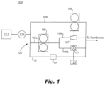
- FIG. 1 an illustrative view of an embodiment of a system in accordance with the disclosure is shown in Fig. 1 and is designated generally by reference character 100.
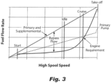
- FIGs. 2 and 3 Other embodiments and/or aspects of this disclosure are shown in Figs. 2 and 3 .
- the systems and methods described herein can be used to reduce circulated bypass flow, reducing waste heat addition to the fuel in a fuel circuit, for example, or any other suitable use.
- a fuel system 100, 200 (e.g., of an aircraft) for an engine (e.g., a turbomachine, not shown) can include a fuel circuit 101, 201 and a primary fuel pump 103, 203 in fluid communication with the fuel circuit 101 that is configured to pump fuel to the engine as a function of engine speed.
- the primary fuel pump 103, 203 can be can be mechanically driven and mechanically connected to the engine in any suitable manner (e.g., via a shaft and/or gearbox) such that the primary fuel pump 103, 203 is configured to pump fuel to the engine as a function of engine speed (e.g., linearly with engine speed).
- the primary fuel pump 103, 203 is sized such that it cannot alone provide sufficient fuel flow (e.g., it is configured to provide insufficient fuel flow) to the engine during at least one engine speed or speed range.
- the system 100, 200 also includes a supplemental fuel pump 105, 205 in fluid communication with the fuel circuit 101, 201 can be configured to selectively pump fuel to the engine at least during the at least one engine speed or speed range to supplement fuel flow from the primary fuel pump 103, 203 to provide sufficient total fuel flow to the engine during all engine speeds.
- the supplemental fuel pump 105, 205 can make up for the inability of the primary fuel pump 103, 203 to pump enough flow (e.g., during start up and/or takeoff).
- the supplemental fuel pump may not be mechanically connected to the engine.
- the primary fuel pump 103, 203 and the supplemental fuel pump 105, 205 can be positive displacement pumps, for example, or any other suitable type of pump.
- the fuel circuit 101, 201 can include two parallel pump branches 101a, 101b, and 201a, 201b. As shown, the primary fuel pump 103, 203 and the supplemental fuel pump 105, 205 can be connected in parallel by the two parallel pump branches 101a, 101b, and 201a, 201b.
- the primary fuel pump 103, 203 can be disposed on a first branch 101a, 201a of the two parallel pump branches 101a, 101b and 201a, 201b, and the supplemental fuel pump 105, 205 can be disposed on a second branch 101b, 201b of the two parallel pump branches 101a, 101b, and 201a, 201b.
- the supplemental fuel pump 105 can be operatively connected to a turbine 107 disposed in fluid communication with the fuel circuit 101 downstream of the primary fuel pump 103 such that the turbine 107 is configured to be driven by fuel flow from the primary fuel pump 103.
- the turbine 107 can drive the supplemental fuel pump 105 as a function of flow through the turbine 107.
- the fuel circuit 101 can include at least two parallel branches 109a, 109b downstream of the primary fuel pump 103.
- the turbine 107 can be in fluid communication with a first branch 109a of the at least two parallel branches 109a, 109b.
- the system 100 can include a control valve 111 disposed in fluid communication with a second branch 109b of the at least two parallel branches 109a, 109b.
- the control valve 111 can be configured to selectively allow and/or meter fuel flow therethrough to create a bypass path around the turbine 107 to selectively allow and/or meter flow through the turbine 107. This in turn controls the speed of the supplemental fuel pump 105. For example, the more closed the control valve 111 is, the more flow will flow through turbine 107, and the more supplemental fuel pump 105 will pump fuel.
- the fuel circuit 101 can include a return loop 113 for returning excess fuel flow to the primary fuel pump 103 and/or supplemental fuel pump 105.
- the return loop 113 can include a pressure release valve 114 for allowing flow at a predetermined pressure. It is contemplated that no return loop 113 is necessary in certain embodiments wherein the primary and supplemental fuel pumps 103, 105 are sized and controlled such that a sufficient, but not excess, amount of a fuel is pumped to the engine under all conditions.
- the system 100, 200 can include a boost pump 115, 215 in fluid communication with the fuel circuit 101, 201 between a fuel tank 117, 217 and the primary and supplemental fuel pumps 103, 203, 105, 205.
- the boost pump 115, 215 can be configured to provide a boost pressure to the primary fuel pump 103, 203 and the supplemental fuel pump 105, 205.
- the boost pump 115, 215 can be driven on a common shaft 219 with the primary fuel pump 103, 203 that is mechanically connected to the engine.
- the system 100, 200 can include any other suitable fuel system components (e.g., heat exchangers, valves, return to tank lines in the fuel circuit to circulate excess flow, etc.) as appreciated by those having ordinary skill in the art.
- a valve 223 e.g., a shutoff valve
- the resistance against turning in the supplemental fuel pump 205 and/or the electrical motor 221 can be sufficient to prevent flow from pushing through the supplemental fuel pump 205 when not in use.
- the engine speed or speed range (e.g., where both the primary and supplemental fuel pumps are used together) can be or include a takeoff engine speed or speed range (e.g., full throttle).
- the engine speed or speed range can be or include a startup or windmill engine speed or speed range.
- the system 100, 200 can include a control module 125, 225 configured to control the supplemental fuel pump 205 (e.g., via controlling control valve 111, or electric motor 221).
- the control module 125, 225 can include any suitable hardware and/or software modules to perform any suitable function and/or method of this disclosure.
- the control module 125, 225 can be configured to track a predetermined engine fuel flow requirement, e.g., to provide a total flow substantially equal to or greater than the predetermined engine fuel flow requirement through all operational speeds/flight phases.
- a predetermined engine fuel flow requirement e.g., to provide a total flow substantially equal to or greater than the predetermined engine fuel flow requirement through all operational speeds/flight phases.
- the primary pump line shows that the primary pump 103, 203 cannot pump enough above a cruise power setting as it crosses the engine requirement curve before the maximum of the engine requirement line.
- the control module 125, 225 can cause the supplemental pump to provide supplemental flow to add to the primary flow to cause the primary and supplemental line to rise above the engine requirement curve.
- control module 125, 225 can be configured to operate the supplemental fuel pump 105, 205 to at least partially match the primary and supplemental flow line to the curve of the engine requirement curve (e.g., at and above the point where the primary line intersects the engine requirement curve).
- Embodiments can include any suitable sensor(s) (e.g., connected to controller 101) to sense if flow is going through pressure relief valve 114, for example, and/or to measure the flow going back to the tank 117, and/or to measure pressure on fuel nozzles for sufficiency, or any other suitable sensor.
- the controller 125, 225 can control the supplemental fuel pump 105, 205 to provide the right amount of pressure to fuel the engine and while creating little to no back flow, for example.
- the controller 125, 225 can be open loop to control based on stored data regarding engine requirements (e.g., using data of Fig. 3 for example).
- supplemental pump any suitable number of supplemental pumps can be used (e.g., more than one) and/or controlled independently or dependently of each other.
- Embodiments having multiple independent supplemental pumps may allow for even smaller sizing of the primary fuel pump (which can be limited to having linear flow line as shown in Fig. 3 ) which can allow more accurate tracking of the engine requirement curve.
- the engine requirement curve can be matched completely by the controller to substantially eliminate excess flow and reduce the addition of waste heat to the fuel.
- a method for providing sufficient fuel flow to an engine can include pumping a first fuel flow with a primary fuel pump to the engine, the first fuel flow being insufficient for the engine at at least one engine speed or speed range; and pumping a second fuel flow with a supplemental fuel pump to supplement the first fuel flow to provide sufficient flow to the engine during the at least one engine speed or speed range.
- Pumping a fuel flow can include driving a turbine connected to the supplemental fuel pump with flow from the primary fuel pump to drive the supplemental fuel pump to provide more flow to the engine than pumped by the primary fuel pump alone.
- the method can include controlling a control valve on a parallel branch from the turbine to meter an amount of flow through the turbine to control a speed of the supplemental fuel pump to control an amount of total flow.
- a method for providing sufficient fuel flow to an engine can include pumping a fuel flow with a mechanically driven primary fuel pump connected to the engine, and with a supplemental fuel pump not mechanically connected to the engine during at least one engine speed or speed range to provide sufficient flow to the engine.
- the primary fuel pump or the supplemental fuel pump alone cannot provide sufficient fuel to the engine.
- Any other suitable methods and/or portions thereof are contemplated herein. Any suitable embodiment(s) of a method and/or portion(s) thereof can be stored as computer executable instructions (e.g., in a non-transitory computer readable medium) and executed by a suitable controller (e.g., a FADEC) or other suitable computing device.
- a suitable controller e.g., a FADEC
- the primary pump can easily provide enough pressure to provide useful work to the turbine to drive the supplemental pump providing the additional flow required.
- Embodiments can include a pressure relief valve to protect against over-pressure.
- Embodiments having an electrically driven fuel pump allow the pump speed and engine speed to be decoupled, thus enabling the pump speed, and therefore flow, to be matched to engine demand.
- Embodiments include reliable, mechanical primary pumps that are sized to provide sufficient flow for the majority of the mission without being vastly oversized at cruise, for example. This reduces wasted energy and unnecessary heating of the fuel. This reduction in waste heat enables the fuel to be utilized for cooling of other aircraft or engine heat loads, which improves the overall aircraft thermal management system efficiency, size and weight. Certain embodiments also enable a small reduction in the parasitic horsepower extraction to drive the fuel pump.
- aspects of the present disclosure may be embodied as a system, method or computer program product. Accordingly, aspects of this disclosure may take the form of an entirely hardware embodiment, an entirely software embodiment (including firmware, resident software, micro-code, etc.), or an embodiment combining software and hardware aspects, all possibilities of which can be referred to herein as a "circuit,” “module,” or “system.”
- a “circuit,” “module,” or “system” can include one or more portions of one or more separate physical hardware and/or software components that can together perform the disclosed function of the "circuit,” “module,” or “system”, or a “circuit,” “module,” or “system” can be a single self-contained unit (e.g., of hardware and/or software).
- aspects of this disclosure may take the form of a computer program product embodied in one or more computer readable medium(s) having computer readable program code embodied thereon.
- the computer readable medium may be a computer readable signal medium or a computer readable storage medium.
- a computer readable storage medium may be, for example, but not limited to, an electronic, magnetic, optical, electromagnetic, infrared, or semiconductor system, apparatus, or device, or any suitable combination of the foregoing.
- a computer readable storage medium may be any tangible medium that can contain, or store a program for use by or in connection with an instruction execution system, apparatus, or device.
- a computer readable signal medium may include a propagated data signal with computer readable program code embodied therein, for example, in baseband or as part of a carrier wave. Such a propagated signal may take any of a variety of forms, including, but not limited to, electro-magnetic, optical, or any suitable combination thereof.
- a computer readable signal medium may be any computer readable medium that is not a computer readable storage medium and that can communicate, propagate, or transport a program for use by or in connection with an instruction execution system, apparatus, or device.
- Program code embodied on a computer readable medium may be transmitted using any appropriate medium, including but not limited to wireless, wireline, optical fiber cable, RF, etc., or any suitable combination of the foregoing.
- Computer program code for carrying out operations for aspects of this disclosure may be written in any combination of one or more programming languages, including an object oriented programming language such as Java, Smalltalk, C++ or the like and conventional procedural programming languages, such as the "C" programming language or similar programming languages.
- the program code may execute entirely on the user's computer, partly on the user's computer, as a stand-alone software package, partly on the user's computer and partly on a remote computer or entirely on the remote computer or server.
- the remote computer may be connected to the user's computer through any type of network, including a local area network (LAN) or a wide area network (WAN), or the connection may be made to an external computer (for example, through the Internet using an Internet Service Provider).
- LAN local area network
- WAN wide area network
- Internet Service Provider for example, AT&T, MCI, Sprint, EarthLink, MSN, GTE, etc.
- These computer program instructions may also be stored in a computer readable medium that can direct a computer, other programmable data processing apparatus, or other devices to function in a particular manner, such that the instructions stored in the computer readable medium produce an article of manufacture including instructions which implement the function/act specified in the flowchart and/or block diagram block or blocks.
- the computer program instructions may also be loaded onto a computer, other programmable data processing apparatus, or other devices to cause a series of operational steps to be performed on the computer, other programmable apparatus or other devices to produce a computer implemented process such that the instructions which execute on the computer or other programmable apparatus provide processes for implementing the functions/acts specified herein.
- any numerical values disclosed herein can be exact values or can be values within a range. Further, any terms of approximation (e.g., “about”, “approximately”, “around”) used in this disclosure can mean the stated value within a range. For example, in certain embodiments, the range can be within (plus or minus) 20%, or within 10%, or within 5%, or within 2%, or within any other suitable percentage or number as appreciated by those having ordinary skill in the art (e.g., for known tolerance limits or error ranges).
Landscapes
- Engineering & Computer Science (AREA)
- Chemical & Material Sciences (AREA)
- Combustion & Propulsion (AREA)
- Mechanical Engineering (AREA)
- General Engineering & Computer Science (AREA)
- Structures Of Non-Positive Displacement Pumps (AREA)
- Control Of Non-Positive-Displacement Pumps (AREA)
Claims (10)
- Kraftstoffsystem für ein Triebwerk, umfassend:einen Kraftstoffkreislauf (101, 201);eine primäre Kraftstoffpumpe (103, 203) in Fluidverbindung mit dem Kraftstoffkreislauf, die dazu konfiguriert ist, einen zum Betreiben des Triebwerks bei mindestens einer Triebwerkdrehzahl oder einem Triebwerkdrehzahlbereich ungenügenden Kraftstoffstrom zum Triebwerk zu pumpen, wobei die primäre Kraftstoffpumpe mechanisch angetrieben und mechanisch mit dem Triebwerk verbunden ist, sodass die primäre Kraftstoffpumpe dazu konfiguriert ist, Kraftstoff in Abhängigkeit von der Triebwerkdrehzahl zu pumpen;eine zusätzliche Kraftstoffpumpe (105, 205) in Fluidverbindung mit dem Kraftstoffkreislauf, die dazu konfiguriert ist, Kraftstoff mindestens während der einen Triebwerkdrehzahl oder des einen Triebwerkdrehzahlbereichs selektiv zum Triebwerk zu pumpen, um den Kraftstoffstrom von der primären Kraftstoffpumpe zum Bereitstellen von ausreichend Gesamtkraftstoffstrom am Triebwerk zum Betreiben des Triebwerks bei allen Triebwerkdrehzahlen zu ergänzen; und dadurch gekennzeichnet, dass:die zusätzliche Kraftstoffpumpe nicht mechanisch mit dem Triebwerk verbunden ist und mit einer Turbine (107) wirkverbunden ist, die stromabwärts der primären Kraftstoffpumpe in Fluidverbindung mit dem Kraftstoffkreislauf angeordnet ist, sodass die Turbine dazu konfiguriert ist, durch den Kraftstoffstrom von der primären Kraftstoffpumpe angetrieben zu werden; und wobei der Kraftstoffkreislauf ferner mindestens zwei parallele Zweige stromabwärts der primären Kraftstoffpumpe umfasst, wobei die Turbine in Fluidverbindung mit einem ersten Zweig der mindestens zwei parallelen Zweige ist; undferner umfassend ein Steuerventil (111), das in Fluidverbindung mit einem zweiten Zweig der mindestens zwei parallelen Zweige angeordnet ist, wobei das Steuerventil dazu konfiguriert ist, Kraftstoffstrom dadurch selektiv zuzulassen und/oder zu dosieren, um zum selektiven Zulassen und/oder Dosieren von Strom durch die Turbine und somit einer Drehzahl der zusätzlichen Kraftstoffpumpe einen Bypasspfad um die Turbine zu erzeugen, und wobei das Steuerventil dazu konfiguriert ist, Strom in dem zweiten Zweig zum Steuern von Kraftstoffstrom zu der Turbine zu unterbrechen, wobei die primäre Kraftstoffpumpe über den ersten Zweig ohne ein Ventil dazwischen mit der Turbine verbunden ist, um einen ununterbrochenen Strom zur Turbine bereitzustellen, und wobei der erste Zweig und der zweite Zweig beide zu einer Brennkammer führen.
- Kraftstoffsystem nach Anspruch 1, wobei die primäre Kraftstoffpumpe und die zusätzliche Kraftstoffpumpe Verdrängerpumpen sind.
- Kraftstoffsystem nach Anspruch 1 oder 2, wobei der Kraftstoffkreislauf zwei parallele Pumpenzweige (101a, 101b) beinhaltet, wobei die primäre Kraftstoffpumpe und die zusätzliche Kraftstoffpumpe durch die beiden parallelen Pumpenzweige parallel verbunden sind, wobei die primäre Kraftstoffpumpe in einem ersten Zweig der beiden parallelen Pumpenzweige angeordnet ist und die zusätzliche Kraftstoffpumpe in einem zweiten Zweig der beiden parallelen Pumpenzweige angeordnet ist.
- Kraftstoffsystem nach einem der vorhergehenden Ansprüche, wobei der Kraftstoffkreislauf einen Rücklaufkreis (113) zum Zurückführen von überschüssigem Kraftstoffstrom zu der primären Kraftstoffpumpe und/oder zusätzlichen Kraftstoffpumpe beinhaltet, wobei der Rücklaufkreis ein Druckentlastungsventil zum Ermöglichen von Strom mit einem vorgegebenen Druck beinhaltet.
- Kraftstoffsystem nach einem der vorhergehenden Ansprüche, ferner umfassend eine Druckverstärkungspumpe (115) in Fluidverbindung mit dem Kraftstoffkreislauf zwischen einem Kraftstofftank (117) und der primären und zusätzlichen Kraftstoffpumpe, wobei die Druckverstärkungspumpe dazu konfiguriert ist, einen Verstärkungsdruck an der primären Kraftstoffpumpe und der zusätzlichen Kraftstoffpumpe bereitzustellen.
- Kraftstoffsystem nach Anspruch 5, wobei die Druckverstärkungspumpe auf einer gemeinsamen Welle (219) mit der primären Kraftstoffpumpe angetrieben wird.
- Kraftstoffsystem nach einem der vorhergehenden Ansprüche, wobei die Triebwerkdrehzahl oder der Triebwerkdrehzahlbereich eine Starttriebwerkdrehzahl oder ein Starttriebwerkdrehzahlbereich ist oder wobei die Triebwerkdrehzahl oder der Triebwerkdrehzahlbereich eine Anlauf- oder Leerlauf-Triebwerkdrehzahl oder ein Anlauf- oder Leerlauf-Triebwerkdrehzahlbereich ist.
- Kraftstoffsystem nach einem der vorhergehenden Ansprüche, ferner umfassend ein Steuermodul (125), das dazu konfiguriert ist, die zusätzliche Kraftstoffpumpe so zu steuern, dass sie einen vorgegebenen Kraftstoffstrombedarf des Triebwerks verfolgt, um einen Gesamtstrom bereitzustellen, der im Wesentlichen gleich dem oder größer als der vorgegebene Kraftstoffstrombedarf des Triebwerks ist.
- Verfahren zum Bereitstellen eines Kraftstoffstroms an einem Triebwerk, umfassend:Pumpen eines ersten Kraftstoffstroms mit einer primären Kraftstoffpumpe zu dem Triebwerk, wobei der erste Kraftstoffstrom zum Betreiben des Triebwerks bei mindestens einer Triebwerkdrehzahl oder einem Triebwerkdrehzahlbereich ungenügend ist; wobei zwei parallele Zweige, ein erster Zweig und ein zweiter Zweig, in Fluidverbindung mit und stromabwärts von der primären Kraftstoffpumpe vorgesehen sind;Pumpen eines zweiten Kraftstoffstroms mit einer zusätzlichen Kraftstoffpumpe, um den ersten Kraftstoffstrom zum Triebwerk zum Bereitstellen von ausreichend Strom zum Betreiben des Triebwerks bei mindestens der einen Triebwerkdrehzahl oder dem einen Triebwerkdrehzahlbereich zu ergänzen; und dadurch gekennzeichnet, dass:Pumpen des ersten und zweiten Kraftstoffstroms Antreiben einer mit der zusätzlichen Kraftstoffpumpe verbundenen Turbine mit Strom von der primären Kraftstoffpumpe zum Antreiben der zusätzlichen Kraftstoffpumpe zum Bereitstellen von mehr Strom an dem Triebwerk als durch die primäre Kraftstoffpumpe allein gepumpt beinhaltet; undferner umfassend Steuern eines Steuerventils in dem zweiten Zweig parallel von der Turbine zum Dosieren einer Menge von Strom durch die Turbine und zum Steuern einer Drehzahl der zusätzlichen Kraftstoffpumpe zum Steuern einer Menge von Gesamtstrom, wobei das Steuerventil dazu konfiguriert ist, Strom in dem zweiten Zweig zum Steuern von Kraftstoffstrom zu der Turbine zu unterbrechen, wobei die primäre Kraftstoffpumpe über den ersten Zweig ohne ein Ventil dazwischen mit der Turbine verbunden ist, um einen ununterbrochenen Strom zur Turbine bereitzustellen, und wobei der erste Zweig und der zweite Zweig beide zu einer Brennkammer führen.
- Verfahren nach Anspruch 9, ferner umfassend Steuern des Gesamtstroms zum Verfolgen eines vorgegebenen Kraftstoffstrombedarfs des Triebwerks.
Applications Claiming Priority (1)
| Application Number | Priority Date | Filing Date | Title |
|---|---|---|---|
| US16/218,865 US11060461B2 (en) | 2018-12-13 | 2018-12-13 | Fuel systems having reduced bypass flow |
Publications (2)
| Publication Number | Publication Date |
|---|---|
| EP3667047A1 EP3667047A1 (de) | 2020-06-17 |
| EP3667047B1 true EP3667047B1 (de) | 2023-09-13 |
Family
ID=68917441
Family Applications (1)
| Application Number | Title | Priority Date | Filing Date |
|---|---|---|---|
| EP19216293.1A Active EP3667047B1 (de) | 2018-12-13 | 2019-12-13 | Kraftstoffsysteme mit verringertem bypass-strom |
Country Status (2)
| Country | Link |
|---|---|
| US (1) | US11060461B2 (de) |
| EP (1) | EP3667047B1 (de) |
Families Citing this family (11)
| Publication number | Priority date | Publication date | Assignee | Title |
|---|---|---|---|---|
| FR3098254B1 (fr) * | 2019-07-03 | 2021-06-11 | Safran Helicopter Engines | Turbogénérateur avec système de régulation simplifié pour aéronef |
| EP4023871B1 (de) * | 2019-08-30 | 2025-08-06 | Kawasaki Jukogyo Kabushiki Kaisha | Gasturbinentriebwerk |
| US11629652B2 (en) * | 2020-02-05 | 2023-04-18 | Hamilton Sundstrand Corporation | Metering pump system |
| US12031492B2 (en) * | 2021-10-12 | 2024-07-09 | Hamilton Sundstrand Corporation | Electric fuel control closed loop aircraft fuel system |
| US11629643B1 (en) * | 2022-01-07 | 2023-04-18 | Hamilton Sundstrand Corporation | Fuel pump systems |
| US12110827B1 (en) | 2023-05-03 | 2024-10-08 | General Electric Company | Fuel systems for aircraft engines |
| US12366240B2 (en) | 2023-05-26 | 2025-07-22 | Hamilton Sundstrand Corporation | Pressure controlled pump systems |
| US12209537B1 (en) * | 2023-07-25 | 2025-01-28 | Hamilton Sundstrand Corporation | Hydraulic motoring of engine |
| US12253029B2 (en) | 2023-08-07 | 2025-03-18 | Hamilton Sundstrand Corporation | Fuel system for dual use gas turbine engine main fuel pump |
| US12352211B1 (en) | 2024-02-28 | 2025-07-08 | Hamilton Sundstrand Corporation | Dual pump electrified fuel system with parallelism |
| US12524027B2 (en) | 2024-04-22 | 2026-01-13 | Hamilton Sundstrand Corporation | Fuel system with boosted and cooled variable displacement main fuel pump and electromechanical actuators |
Family Cites Families (25)
| Publication number | Priority date | Publication date | Assignee | Title |
|---|---|---|---|---|
| US2916875A (en) * | 1953-09-09 | 1959-12-15 | Rolls Royce | Gas turbine engine fuel systems |
| US3664509A (en) * | 1969-11-04 | 1972-05-23 | Trw Inc | Fluids flow system with self-flushing revolving filter |
| US4205945A (en) * | 1974-11-29 | 1980-06-03 | General Electric Company | Unitized fluid delivery system and method of operating same |
| US4339917A (en) * | 1979-06-13 | 1982-07-20 | The Garrett Corporation | Fuel delivery system and method |
| US4864815A (en) * | 1987-12-24 | 1989-09-12 | Sundstrand Corporation | Fuel supply system with turbine driven start pump |
| FR2666118B1 (fr) * | 1990-08-22 | 1992-10-30 | Snecma | Circuit d'alimentation en carburant d'un turbo-moteur. |
| US5118258A (en) * | 1990-09-04 | 1992-06-02 | United Technologies Corporation | Dual pump fuel delivery system |
| GB2282186B (en) * | 1993-09-08 | 1997-09-24 | Rolls Royce Plc | Engine fuel metering system |
| EP1819914A2 (de) * | 2004-11-19 | 2007-08-22 | Goodrich Pump & Engine Control Systems, Inc. | Zweistufen-treibstoffpumpe für gasturbinen |
| US7401461B2 (en) * | 2005-05-27 | 2008-07-22 | Honeywell International Inc. | Reduced-weight fuel system for gas turbine engine, gas turbine engine having a reduced-weight fuel system, and method of providing fuel to a gas turbine engine using a reduced-weight fuel system |
| US8256222B2 (en) * | 2008-02-11 | 2012-09-04 | Honeywell International Inc. | Direct metering fuel control with integral electrical metering pump and actuator servo pump |
| US8166765B2 (en) | 2008-10-15 | 2012-05-01 | Woodward, Inc. | Fuel delivery and control system including a variable displacement actuation pump supplementing a fixed displacement main pump |
| US8302406B2 (en) | 2008-10-15 | 2012-11-06 | Woodward, Inc. | Fuel delivery and control system including a positive displacement actuation pump with a variable pressure regulator supplementing a fixed displacement main fuel pump |
| US8276360B2 (en) | 2009-05-22 | 2012-10-02 | Hamilton Sundstrand Corporation | Dual-pump fuel system and method for starting a gas turbine engine |
| FR2950863B1 (fr) * | 2009-10-06 | 2012-03-02 | Snecma | Circuit d'alimentation en carburant d'un moteur d'aeronef |
| FR2953563B1 (fr) | 2009-12-07 | 2012-02-03 | Snecma | Installation d'alimentation en carburant d'un turboreacteur d'avion |
| US8991152B2 (en) | 2011-01-24 | 2015-03-31 | Hamilton Sundstrand Corporation | Aircraft engine fuel system |
| GB201102772D0 (en) | 2011-02-17 | 2011-03-30 | Rolls Royce Goodrich Engine Control Systems Ltd | Pumping arrangement |
| US8893466B2 (en) | 2011-03-18 | 2014-11-25 | Hamilton Sundstrand Corporation | Dual pump fuel flow system for a gas turbine engine and method of controlling |
| US9316157B2 (en) | 2012-02-01 | 2016-04-19 | Hamilton Sundstrand Corporation | Fuel system for starting an APU using a hybrid pump arrangement |
| US9399953B2 (en) * | 2012-09-19 | 2016-07-26 | Hamilton Sundstrand Corporation | Gas turbine engine fuel system pump sharing valve |
| US9453463B2 (en) | 2013-01-17 | 2016-09-27 | Honeywell International Inc. | High efficiency, high pressure gas turbine engine fuel supply system |
| US9657643B2 (en) | 2013-10-16 | 2017-05-23 | Hamilton Sundstrand Corporation | Energy efficient pump system |
| US9885287B2 (en) * | 2014-09-11 | 2018-02-06 | Honeywell International Inc. | Gas turbine engine mechanical-electrical hybrid fuel delivery system |
| US20180050812A1 (en) | 2016-08-16 | 2018-02-22 | Hamilton Sundstrand Corporation | Aircraft fuel pump systems |
-
2018
- 2018-12-13 US US16/218,865 patent/US11060461B2/en active Active
-
2019
- 2019-12-13 EP EP19216293.1A patent/EP3667047B1/de active Active
Also Published As
| Publication number | Publication date |
|---|---|
| EP3667047A1 (de) | 2020-06-17 |
| US11060461B2 (en) | 2021-07-13 |
| US20200191058A1 (en) | 2020-06-18 |
Similar Documents
| Publication | Publication Date | Title |
|---|---|---|
| EP3667047B1 (de) | Kraftstoffsysteme mit verringertem bypass-strom | |
| EP3530909B1 (de) | Kraftstoffpumpensysteme für turbomaschinen | |
| EP3232036B1 (de) | Doppelpumpen-kraftstoffsystem mit pumpenteilungsverbindung | |
| US11649038B2 (en) | Hybrid electric powerplant (HEP) control architecture | |
| EP4209680B1 (de) | Kraftstoffpumpensysteme | |
| EP2182206A2 (de) | Hydraulisches System und Windturbinengenerator damit | |
| US11708795B1 (en) | Systems and methods for bleed valve control in fuel systems | |
| US10823074B2 (en) | Recirculation of fluid through a turbomachine centrifugal pump | |
| US12071898B2 (en) | Fluid pump systems | |
| CA2924853A1 (en) | Controller modulated oil system for a gas turbine propulsion system | |
| US20180371945A1 (en) | System and method for supplying lubrication fluid to at least one member of an aircraft propulsion assembly | |
| EP4134534B1 (de) | Steuerung für elektrisch unterstützte turbinen | |
| EP2508720B1 (de) | Verfahren zur Regelung eines Kraftwerks und System zur Erhöhung der operativen Flexibilität eines Kraftwerks | |
| EP4187073A1 (de) | Flüssigkeitsabgabesysteme | |
| EP4484730A1 (de) | Kraftstoffsysteme | |
| US11028726B2 (en) | Starter air valve systems configured for low speed motoring | |
| EP4191039B1 (de) | Kraftstoffpumpensysteme | |
| EP4467800B1 (de) | Flüssigkeitspumpensysteme | |
| US12366240B2 (en) | Pressure controlled pump systems | |
| US20240392725A1 (en) | Fuel systems having thermal recirculation | |
| US12209537B1 (en) | Hydraulic motoring of engine | |
| CN113646521B (zh) | 用控制饱和度管理控制涡轮发动机的方法和系统 | |
| EP3343003B1 (de) | Verfahren eines niedrig-drehzahl-antriebs mittels pneumatikventilsystem |
Legal Events
| Date | Code | Title | Description |
|---|---|---|---|
| PUAI | Public reference made under article 153(3) epc to a published international application that has entered the european phase |
Free format text: ORIGINAL CODE: 0009012 |
|
| STAA | Information on the status of an ep patent application or granted ep patent |
Free format text: STATUS: THE APPLICATION HAS BEEN PUBLISHED |
|
| AK | Designated contracting states |
Kind code of ref document: A1 Designated state(s): AL AT BE BG CH CY CZ DE DK EE ES FI FR GB GR HR HU IE IS IT LI LT LU LV MC MK MT NL NO PL PT RO RS SE SI SK SM TR |
|
| STAA | Information on the status of an ep patent application or granted ep patent |
Free format text: STATUS: REQUEST FOR EXAMINATION WAS MADE |
|
| 17P | Request for examination filed |
Effective date: 20201217 |
|
| RBV | Designated contracting states (corrected) |
Designated state(s): AL AT BE BG CH CY CZ DE DK EE ES FI FR GB GR HR HU IE IS IT LI LT LU LV MC MK MT NL NO PL PT RO RS SE SI SK SM TR |
|
| STAA | Information on the status of an ep patent application or granted ep patent |
Free format text: STATUS: EXAMINATION IS IN PROGRESS |
|
| 17Q | First examination report despatched |
Effective date: 20210615 |
|
| GRAP | Despatch of communication of intention to grant a patent |
Free format text: ORIGINAL CODE: EPIDOSNIGR1 |
|
| STAA | Information on the status of an ep patent application or granted ep patent |
Free format text: STATUS: GRANT OF PATENT IS INTENDED |
|
| INTG | Intention to grant announced |
Effective date: 20230329 |
|
| GRAS | Grant fee paid |
Free format text: ORIGINAL CODE: EPIDOSNIGR3 |
|
| GRAA | (expected) grant |
Free format text: ORIGINAL CODE: 0009210 |
|
| STAA | Information on the status of an ep patent application or granted ep patent |
Free format text: STATUS: THE PATENT HAS BEEN GRANTED |
|
| AK | Designated contracting states |
Kind code of ref document: B1 Designated state(s): AL AT BE BG CH CY CZ DE DK EE ES FI FR GB GR HR HU IE IS IT LI LT LU LV MC MK MT NL NO PL PT RO RS SE SI SK SM TR |
|
| REG | Reference to a national code |
Ref country code: CH Ref legal event code: EP |
|
| REG | Reference to a national code |
Ref country code: DE Ref legal event code: R096 Ref document number: 602019037275 Country of ref document: DE |
|
| REG | Reference to a national code |
Ref country code: IE Ref legal event code: FG4D |
|
| REG | Reference to a national code |
Ref country code: LT Ref legal event code: MG9D |
|
| REG | Reference to a national code |
Ref country code: NL Ref legal event code: MP Effective date: 20230913 |
|
| PG25 | Lapsed in a contracting state [announced via postgrant information from national office to epo] |
Ref country code: GR Free format text: LAPSE BECAUSE OF FAILURE TO SUBMIT A TRANSLATION OF THE DESCRIPTION OR TO PAY THE FEE WITHIN THE PRESCRIBED TIME-LIMIT Effective date: 20231214 |
|
| PG25 | Lapsed in a contracting state [announced via postgrant information from national office to epo] |
Ref country code: SE Free format text: LAPSE BECAUSE OF FAILURE TO SUBMIT A TRANSLATION OF THE DESCRIPTION OR TO PAY THE FEE WITHIN THE PRESCRIBED TIME-LIMIT Effective date: 20230913 Ref country code: RS Free format text: LAPSE BECAUSE OF FAILURE TO SUBMIT A TRANSLATION OF THE DESCRIPTION OR TO PAY THE FEE WITHIN THE PRESCRIBED TIME-LIMIT Effective date: 20230913 Ref country code: NO Free format text: LAPSE BECAUSE OF FAILURE TO SUBMIT A TRANSLATION OF THE DESCRIPTION OR TO PAY THE FEE WITHIN THE PRESCRIBED TIME-LIMIT Effective date: 20231213 Ref country code: LV Free format text: LAPSE BECAUSE OF FAILURE TO SUBMIT A TRANSLATION OF THE DESCRIPTION OR TO PAY THE FEE WITHIN THE PRESCRIBED TIME-LIMIT Effective date: 20230913 Ref country code: LT Free format text: LAPSE BECAUSE OF FAILURE TO SUBMIT A TRANSLATION OF THE DESCRIPTION OR TO PAY THE FEE WITHIN THE PRESCRIBED TIME-LIMIT Effective date: 20230913 Ref country code: HR Free format text: LAPSE BECAUSE OF FAILURE TO SUBMIT A TRANSLATION OF THE DESCRIPTION OR TO PAY THE FEE WITHIN THE PRESCRIBED TIME-LIMIT Effective date: 20230913 Ref country code: GR Free format text: LAPSE BECAUSE OF FAILURE TO SUBMIT A TRANSLATION OF THE DESCRIPTION OR TO PAY THE FEE WITHIN THE PRESCRIBED TIME-LIMIT Effective date: 20231214 Ref country code: FI Free format text: LAPSE BECAUSE OF FAILURE TO SUBMIT A TRANSLATION OF THE DESCRIPTION OR TO PAY THE FEE WITHIN THE PRESCRIBED TIME-LIMIT Effective date: 20230913 |
|
| REG | Reference to a national code |
Ref country code: AT Ref legal event code: MK05 Ref document number: 1611525 Country of ref document: AT Kind code of ref document: T Effective date: 20230913 |
|
| PG25 | Lapsed in a contracting state [announced via postgrant information from national office to epo] |
Ref country code: NL Free format text: LAPSE BECAUSE OF FAILURE TO SUBMIT A TRANSLATION OF THE DESCRIPTION OR TO PAY THE FEE WITHIN THE PRESCRIBED TIME-LIMIT Effective date: 20230913 |
|
| PG25 | Lapsed in a contracting state [announced via postgrant information from national office to epo] |
Ref country code: IS Free format text: LAPSE BECAUSE OF FAILURE TO SUBMIT A TRANSLATION OF THE DESCRIPTION OR TO PAY THE FEE WITHIN THE PRESCRIBED TIME-LIMIT Effective date: 20240113 |
|
| PG25 | Lapsed in a contracting state [announced via postgrant information from national office to epo] |
Ref country code: AT Free format text: LAPSE BECAUSE OF FAILURE TO SUBMIT A TRANSLATION OF THE DESCRIPTION OR TO PAY THE FEE WITHIN THE PRESCRIBED TIME-LIMIT Effective date: 20230913 |
|
| PG25 | Lapsed in a contracting state [announced via postgrant information from national office to epo] |
Ref country code: ES Free format text: LAPSE BECAUSE OF FAILURE TO SUBMIT A TRANSLATION OF THE DESCRIPTION OR TO PAY THE FEE WITHIN THE PRESCRIBED TIME-LIMIT Effective date: 20230913 |
|
| PG25 | Lapsed in a contracting state [announced via postgrant information from national office to epo] |
Ref country code: SM Free format text: LAPSE BECAUSE OF FAILURE TO SUBMIT A TRANSLATION OF THE DESCRIPTION OR TO PAY THE FEE WITHIN THE PRESCRIBED TIME-LIMIT Effective date: 20230913 Ref country code: RO Free format text: LAPSE BECAUSE OF FAILURE TO SUBMIT A TRANSLATION OF THE DESCRIPTION OR TO PAY THE FEE WITHIN THE PRESCRIBED TIME-LIMIT Effective date: 20230913 Ref country code: IS Free format text: LAPSE BECAUSE OF FAILURE TO SUBMIT A TRANSLATION OF THE DESCRIPTION OR TO PAY THE FEE WITHIN THE PRESCRIBED TIME-LIMIT Effective date: 20240113 Ref country code: ES Free format text: LAPSE BECAUSE OF FAILURE TO SUBMIT A TRANSLATION OF THE DESCRIPTION OR TO PAY THE FEE WITHIN THE PRESCRIBED TIME-LIMIT Effective date: 20230913 Ref country code: EE Free format text: LAPSE BECAUSE OF FAILURE TO SUBMIT A TRANSLATION OF THE DESCRIPTION OR TO PAY THE FEE WITHIN THE PRESCRIBED TIME-LIMIT Effective date: 20230913 Ref country code: CZ Free format text: LAPSE BECAUSE OF FAILURE TO SUBMIT A TRANSLATION OF THE DESCRIPTION OR TO PAY THE FEE WITHIN THE PRESCRIBED TIME-LIMIT Effective date: 20230913 Ref country code: AT Free format text: LAPSE BECAUSE OF FAILURE TO SUBMIT A TRANSLATION OF THE DESCRIPTION OR TO PAY THE FEE WITHIN THE PRESCRIBED TIME-LIMIT Effective date: 20230913 Ref country code: PT Free format text: LAPSE BECAUSE OF FAILURE TO SUBMIT A TRANSLATION OF THE DESCRIPTION OR TO PAY THE FEE WITHIN THE PRESCRIBED TIME-LIMIT Effective date: 20240115 Ref country code: SK Free format text: LAPSE BECAUSE OF FAILURE TO SUBMIT A TRANSLATION OF THE DESCRIPTION OR TO PAY THE FEE WITHIN THE PRESCRIBED TIME-LIMIT Effective date: 20230913 |
|
| PG25 | Lapsed in a contracting state [announced via postgrant information from national office to epo] |
Ref country code: PL Free format text: LAPSE BECAUSE OF FAILURE TO SUBMIT A TRANSLATION OF THE DESCRIPTION OR TO PAY THE FEE WITHIN THE PRESCRIBED TIME-LIMIT Effective date: 20230913 Ref country code: IT Free format text: LAPSE BECAUSE OF FAILURE TO SUBMIT A TRANSLATION OF THE DESCRIPTION OR TO PAY THE FEE WITHIN THE PRESCRIBED TIME-LIMIT Effective date: 20230913 |
|
| REG | Reference to a national code |
Ref country code: DE Ref legal event code: R097 Ref document number: 602019037275 Country of ref document: DE |
|
| PG25 | Lapsed in a contracting state [announced via postgrant information from national office to epo] |
Ref country code: DK Free format text: LAPSE BECAUSE OF FAILURE TO SUBMIT A TRANSLATION OF THE DESCRIPTION OR TO PAY THE FEE WITHIN THE PRESCRIBED TIME-LIMIT Effective date: 20230913 |
|
| PLBE | No opposition filed within time limit |
Free format text: ORIGINAL CODE: 0009261 |
|
| STAA | Information on the status of an ep patent application or granted ep patent |
Free format text: STATUS: NO OPPOSITION FILED WITHIN TIME LIMIT |
|
| PG25 | Lapsed in a contracting state [announced via postgrant information from national office to epo] |
Ref country code: DK Free format text: LAPSE BECAUSE OF FAILURE TO SUBMIT A TRANSLATION OF THE DESCRIPTION OR TO PAY THE FEE WITHIN THE PRESCRIBED TIME-LIMIT Effective date: 20230913 |
|
| REG | Reference to a national code |
Ref country code: CH Ref legal event code: PL |
|
| 26N | No opposition filed |
Effective date: 20240614 |
|
| PG25 | Lapsed in a contracting state [announced via postgrant information from national office to epo] |
Ref country code: LU Free format text: LAPSE BECAUSE OF NON-PAYMENT OF DUE FEES Effective date: 20231213 |
|
| PG25 | Lapsed in a contracting state [announced via postgrant information from national office to epo] |
Ref country code: MC Free format text: LAPSE BECAUSE OF FAILURE TO SUBMIT A TRANSLATION OF THE DESCRIPTION OR TO PAY THE FEE WITHIN THE PRESCRIBED TIME-LIMIT Effective date: 20230913 |
|
| REG | Reference to a national code |
Ref country code: BE Ref legal event code: MM Effective date: 20231231 |
|
| PG25 | Lapsed in a contracting state [announced via postgrant information from national office to epo] |
Ref country code: MC Free format text: LAPSE BECAUSE OF FAILURE TO SUBMIT A TRANSLATION OF THE DESCRIPTION OR TO PAY THE FEE WITHIN THE PRESCRIBED TIME-LIMIT Effective date: 20230913 Ref country code: LU Free format text: LAPSE BECAUSE OF NON-PAYMENT OF DUE FEES Effective date: 20231213 |
|
| REG | Reference to a national code |
Ref country code: IE Ref legal event code: MM4A |
|
| PG25 | Lapsed in a contracting state [announced via postgrant information from national office to epo] |
Ref country code: IE Free format text: LAPSE BECAUSE OF NON-PAYMENT OF DUE FEES Effective date: 20231213 |
|
| PG25 | Lapsed in a contracting state [announced via postgrant information from national office to epo] |
Ref country code: BE Free format text: LAPSE BECAUSE OF NON-PAYMENT OF DUE FEES Effective date: 20231231 |
|
| PG25 | Lapsed in a contracting state [announced via postgrant information from national office to epo] |
Ref country code: CH Free format text: LAPSE BECAUSE OF NON-PAYMENT OF DUE FEES Effective date: 20231231 |
|
| PG25 | Lapsed in a contracting state [announced via postgrant information from national office to epo] |
Ref country code: SI Free format text: LAPSE BECAUSE OF FAILURE TO SUBMIT A TRANSLATION OF THE DESCRIPTION OR TO PAY THE FEE WITHIN THE PRESCRIBED TIME-LIMIT Effective date: 20230913 |
|
| PG25 | Lapsed in a contracting state [announced via postgrant information from national office to epo] |
Ref country code: SI Free format text: LAPSE BECAUSE OF FAILURE TO SUBMIT A TRANSLATION OF THE DESCRIPTION OR TO PAY THE FEE WITHIN THE PRESCRIBED TIME-LIMIT Effective date: 20230913 Ref country code: IE Free format text: LAPSE BECAUSE OF NON-PAYMENT OF DUE FEES Effective date: 20231213 Ref country code: CH Free format text: LAPSE BECAUSE OF NON-PAYMENT OF DUE FEES Effective date: 20231231 Ref country code: BE Free format text: LAPSE BECAUSE OF NON-PAYMENT OF DUE FEES Effective date: 20231231 |
|
| PG25 | Lapsed in a contracting state [announced via postgrant information from national office to epo] |
Ref country code: BG Free format text: LAPSE BECAUSE OF FAILURE TO SUBMIT A TRANSLATION OF THE DESCRIPTION OR TO PAY THE FEE WITHIN THE PRESCRIBED TIME-LIMIT Effective date: 20230913 |
|
| PG25 | Lapsed in a contracting state [announced via postgrant information from national office to epo] |
Ref country code: BG Free format text: LAPSE BECAUSE OF FAILURE TO SUBMIT A TRANSLATION OF THE DESCRIPTION OR TO PAY THE FEE WITHIN THE PRESCRIBED TIME-LIMIT Effective date: 20230913 |
|
| PG25 | Lapsed in a contracting state [announced via postgrant information from national office to epo] |
Ref country code: CY Free format text: LAPSE BECAUSE OF FAILURE TO SUBMIT A TRANSLATION OF THE DESCRIPTION OR TO PAY THE FEE WITHIN THE PRESCRIBED TIME-LIMIT; INVALID AB INITIO Effective date: 20191213 |
|
| PG25 | Lapsed in a contracting state [announced via postgrant information from national office to epo] |
Ref country code: HU Free format text: LAPSE BECAUSE OF FAILURE TO SUBMIT A TRANSLATION OF THE DESCRIPTION OR TO PAY THE FEE WITHIN THE PRESCRIBED TIME-LIMIT; INVALID AB INITIO Effective date: 20191213 |
|
| PG25 | Lapsed in a contracting state [announced via postgrant information from national office to epo] |
Ref country code: TR Free format text: LAPSE BECAUSE OF FAILURE TO SUBMIT A TRANSLATION OF THE DESCRIPTION OR TO PAY THE FEE WITHIN THE PRESCRIBED TIME-LIMIT Effective date: 20230913 |
|
| PGFP | Annual fee paid to national office [announced via postgrant information from national office to epo] |
Ref country code: DE Payment date: 20251126 Year of fee payment: 7 |
|
| PGFP | Annual fee paid to national office [announced via postgrant information from national office to epo] |
Ref country code: GB Payment date: 20251119 Year of fee payment: 7 |
|
| PGFP | Annual fee paid to national office [announced via postgrant information from national office to epo] |
Ref country code: FR Payment date: 20251119 Year of fee payment: 7 |
|
| P01 | Opt-out of the competence of the unified patent court (upc) registered |
Free format text: CASE NUMBER: UPC_APP_0018918_3667047/2025 Effective date: 20251222 |