EP3667045B1 - Turbocharger system with plural volute members and a rotatable valve - Google Patents
Turbocharger system with plural volute members and a rotatable valve Download PDFInfo
- Publication number
- EP3667045B1 EP3667045B1 EP20156647.8A EP20156647A EP3667045B1 EP 3667045 B1 EP3667045 B1 EP 3667045B1 EP 20156647 A EP20156647 A EP 20156647A EP 3667045 B1 EP3667045 B1 EP 3667045B1
- Authority
- EP
- European Patent Office
- Prior art keywords
- passage
- valve
- valve member
- volute
- axis
- Prior art date
- Legal status (The legal status is an assumption and is not a legal conclusion. Google has not performed a legal analysis and makes no representation as to the accuracy of the status listed.)
- Active
Links
Images



Classifications
-
- F—MECHANICAL ENGINEERING; LIGHTING; HEATING; WEAPONS; BLASTING
- F02—COMBUSTION ENGINES; HOT-GAS OR COMBUSTION-PRODUCT ENGINE PLANTS
- F02B—INTERNAL-COMBUSTION PISTON ENGINES; COMBUSTION ENGINES IN GENERAL
- F02B37/00—Engines characterised by provision of pumps driven at least for part of the time by exhaust
- F02B37/12—Control of the pumps
- F02B37/18—Control of the pumps by bypassing exhaust from the inlet to the outlet of turbine or to the atmosphere
- F02B37/183—Arrangements of bypass valves or actuators therefor
-
- F—MECHANICAL ENGINEERING; LIGHTING; HEATING; WEAPONS; BLASTING
- F01—MACHINES OR ENGINES IN GENERAL; ENGINE PLANTS IN GENERAL; STEAM ENGINES
- F01D—NON-POSITIVE DISPLACEMENT MACHINES OR ENGINES, e.g. STEAM TURBINES
- F01D17/00—Regulating or controlling by varying flow
- F01D17/10—Final actuators
- F01D17/105—Final actuators by passing part of the fluid
-
- F—MECHANICAL ENGINEERING; LIGHTING; HEATING; WEAPONS; BLASTING
- F01—MACHINES OR ENGINES IN GENERAL; ENGINE PLANTS IN GENERAL; STEAM ENGINES
- F01D—NON-POSITIVE DISPLACEMENT MACHINES OR ENGINES, e.g. STEAM TURBINES
- F01D25/00—Component parts, details, or accessories, not provided for in, or of interest apart from, other groups
- F01D25/24—Casings; Casing parts, e.g. diaphragms, casing fastenings
-
- F—MECHANICAL ENGINEERING; LIGHTING; HEATING; WEAPONS; BLASTING
- F01—MACHINES OR ENGINES IN GENERAL; ENGINE PLANTS IN GENERAL; STEAM ENGINES
- F01D—NON-POSITIVE DISPLACEMENT MACHINES OR ENGINES, e.g. STEAM TURBINES
- F01D5/00—Blades; Blade-carrying members; Heating, heat-insulating, cooling or antivibration means on the blades or the members
- F01D5/02—Blade-carrying members, e.g. rotors
- F01D5/04—Blade-carrying members, e.g. rotors for radial-flow machines or engines
-
- F—MECHANICAL ENGINEERING; LIGHTING; HEATING; WEAPONS; BLASTING
- F02—COMBUSTION ENGINES; HOT-GAS OR COMBUSTION-PRODUCT ENGINE PLANTS
- F02B—INTERNAL-COMBUSTION PISTON ENGINES; COMBUSTION ENGINES IN GENERAL
- F02B37/00—Engines characterised by provision of pumps driven at least for part of the time by exhaust
- F02B37/02—Gas passages between engine outlet and pump drive, e.g. reservoirs
- F02B37/025—Multiple scrolls or multiple gas passages guiding the gas to the pump drive
-
- F—MECHANICAL ENGINEERING; LIGHTING; HEATING; WEAPONS; BLASTING
- F02—COMBUSTION ENGINES; HOT-GAS OR COMBUSTION-PRODUCT ENGINE PLANTS
- F02B—INTERNAL-COMBUSTION PISTON ENGINES; COMBUSTION ENGINES IN GENERAL
- F02B37/00—Engines characterised by provision of pumps driven at least for part of the time by exhaust
- F02B37/12—Control of the pumps
- F02B37/18—Control of the pumps by bypassing exhaust from the inlet to the outlet of turbine or to the atmosphere
- F02B37/183—Arrangements of bypass valves or actuators therefor
- F02B37/186—Arrangements of actuators or linkage for bypass valves
-
- F—MECHANICAL ENGINEERING; LIGHTING; HEATING; WEAPONS; BLASTING
- F02—COMBUSTION ENGINES; HOT-GAS OR COMBUSTION-PRODUCT ENGINE PLANTS
- F02B—INTERNAL-COMBUSTION PISTON ENGINES; COMBUSTION ENGINES IN GENERAL
- F02B37/00—Engines characterised by provision of pumps driven at least for part of the time by exhaust
- F02B37/12—Control of the pumps
- F02B37/22—Control of the pumps by varying cross-section of exhaust passages or air passages, e.g. by throttling turbine inlets or outlets or by varying effective number of guide conduits
-
- F—MECHANICAL ENGINEERING; LIGHTING; HEATING; WEAPONS; BLASTING
- F02—COMBUSTION ENGINES; HOT-GAS OR COMBUSTION-PRODUCT ENGINE PLANTS
- F02C—GAS-TURBINE PLANTS; AIR INTAKES FOR JET-PROPULSION PLANTS; CONTROLLING FUEL SUPPLY IN AIR-BREATHING JET-PROPULSION PLANTS
- F02C6/00—Plural gas-turbine plants; Combinations of gas-turbine plants with other apparatus; Adaptations of gas-turbine plants for special use
- F02C6/04—Gas-turbine plants providing heated or pressurised working fluid for other apparatus, e.g. without mechanical power output
- F02C6/10—Gas-turbine plants providing heated or pressurised working fluid for other apparatus, e.g. without mechanical power output supplying working fluid to a user, e.g. a chemical process, which returns working fluid to a turbine of the plant
- F02C6/12—Turbochargers, i.e. plants for augmenting mechanical power output of internal-combustion piston engines by increase of charge pressure
-
- F—MECHANICAL ENGINEERING; LIGHTING; HEATING; WEAPONS; BLASTING
- F02—COMBUSTION ENGINES; HOT-GAS OR COMBUSTION-PRODUCT ENGINE PLANTS
- F02D—CONTROLLING COMBUSTION ENGINES
- F02D41/00—Electrical control of supply of combustible mixture or its constituents
- F02D41/0002—Controlling intake air
- F02D41/0007—Controlling intake air for control of turbo-charged or super-charged engines
-
- F—MECHANICAL ENGINEERING; LIGHTING; HEATING; WEAPONS; BLASTING
- F16—ENGINEERING ELEMENTS AND UNITS; GENERAL MEASURES FOR PRODUCING AND MAINTAINING EFFECTIVE FUNCTIONING OF MACHINES OR INSTALLATIONS; THERMAL INSULATION IN GENERAL
- F16K—VALVES; TAPS; COCKS; ACTUATING-FLOATS; DEVICES FOR VENTING OR AERATING
- F16K11/00—Multiple-way valves, e.g. mixing valves; Pipe fittings incorporating such valves
- F16K11/02—Multiple-way valves, e.g. mixing valves; Pipe fittings incorporating such valves with all movable sealing faces moving as one unit
- F16K11/08—Multiple-way valves, e.g. mixing valves; Pipe fittings incorporating such valves with all movable sealing faces moving as one unit comprising only taps or cocks
- F16K11/085—Multiple-way valves, e.g. mixing valves; Pipe fittings incorporating such valves with all movable sealing faces moving as one unit comprising only taps or cocks with cylindrical plug
- F16K11/0856—Multiple-way valves, e.g. mixing valves; Pipe fittings incorporating such valves with all movable sealing faces moving as one unit comprising only taps or cocks with cylindrical plug having all the connecting conduits situated in more than one plane perpendicular to the axis of the plug
-
- F—MECHANICAL ENGINEERING; LIGHTING; HEATING; WEAPONS; BLASTING
- F16—ENGINEERING ELEMENTS AND UNITS; GENERAL MEASURES FOR PRODUCING AND MAINTAINING EFFECTIVE FUNCTIONING OF MACHINES OR INSTALLATIONS; THERMAL INSULATION IN GENERAL
- F16K—VALVES; TAPS; COCKS; ACTUATING-FLOATS; DEVICES FOR VENTING OR AERATING
- F16K37/00—Special means in or on valves or other cut-off apparatus for indicating or recording operation thereof, or for enabling an alarm to be given
- F16K37/0025—Electrical or magnetic means
- F16K37/005—Electrical or magnetic means for measuring fluid parameters
-
- F—MECHANICAL ENGINEERING; LIGHTING; HEATING; WEAPONS; BLASTING
- F02—COMBUSTION ENGINES; HOT-GAS OR COMBUSTION-PRODUCT ENGINE PLANTS
- F02B—INTERNAL-COMBUSTION PISTON ENGINES; COMBUSTION ENGINES IN GENERAL
- F02B37/00—Engines characterised by provision of pumps driven at least for part of the time by exhaust
- F02B37/12—Control of the pumps
- F02B2037/122—Control of rotational speed of the pump
-
- F—MECHANICAL ENGINEERING; LIGHTING; HEATING; WEAPONS; BLASTING
- F02—COMBUSTION ENGINES; HOT-GAS OR COMBUSTION-PRODUCT ENGINE PLANTS
- F02D—CONTROLLING COMBUSTION ENGINES
- F02D2200/00—Input parameters for engine control
- F02D2200/02—Input parameters for engine control the parameters being related to the engine
- F02D2200/10—Parameters related to the engine output, e.g. engine torque or engine speed
- F02D2200/101—Engine speed
-
- F—MECHANICAL ENGINEERING; LIGHTING; HEATING; WEAPONS; BLASTING
- F05—INDEXING SCHEMES RELATING TO ENGINES OR PUMPS IN VARIOUS SUBCLASSES OF CLASSES F01-F04
- F05D—INDEXING SCHEME FOR ASPECTS RELATING TO NON-POSITIVE-DISPLACEMENT MACHINES OR ENGINES, GAS-TURBINES OR JET-PROPULSION PLANTS
- F05D2220/00—Application
- F05D2220/40—Application in turbochargers
-
- F—MECHANICAL ENGINEERING; LIGHTING; HEATING; WEAPONS; BLASTING
- F05—INDEXING SCHEMES RELATING TO ENGINES OR PUMPS IN VARIOUS SUBCLASSES OF CLASSES F01-F04
- F05D—INDEXING SCHEME FOR ASPECTS RELATING TO NON-POSITIVE-DISPLACEMENT MACHINES OR ENGINES, GAS-TURBINES OR JET-PROPULSION PLANTS
- F05D2250/00—Geometry
- F05D2250/70—Shape
- F05D2250/71—Shape curved
-
- Y—GENERAL TAGGING OF NEW TECHNOLOGICAL DEVELOPMENTS; GENERAL TAGGING OF CROSS-SECTIONAL TECHNOLOGIES SPANNING OVER SEVERAL SECTIONS OF THE IPC; TECHNICAL SUBJECTS COVERED BY FORMER USPC CROSS-REFERENCE ART COLLECTIONS [XRACs] AND DIGESTS
- Y02—TECHNOLOGIES OR APPLICATIONS FOR MITIGATION OR ADAPTATION AGAINST CLIMATE CHANGE
- Y02T—CLIMATE CHANGE MITIGATION TECHNOLOGIES RELATED TO TRANSPORTATION
- Y02T10/00—Road transport of goods or passengers
- Y02T10/10—Internal combustion engine [ICE] based vehicles
- Y02T10/12—Improving ICE efficiencies
Definitions
- the present invention generally relates to a turbocharger system and, more particularly, relates to a turbocharger system with plural volute members and a rotatable valve.
- turbochargers include a turbine wheel and a compressor wheel mounted on a common shaft and carried within isolated turbine and compressor housings, respectively.
- the turbine wheel may be driven in rotation by exhaust gas output by the engine. This, in turn, rotates the compressor wheel for compressing air that is fed to the combustion chambers of the engine. Accordingly, the turbocharger may provide a performance boost and increased efficiency to the engine.
- Turbocharger systems may operate in a number of conditions.
- the turbocharger may operate at relatively low engine speeds, relatively high engine speeds, and at speeds therebetween.
- the turbocharger system may operate at times when the exhaust mass flow is relatively high, low, and therebetween.
- WO 2016/094360 discloses a turbocharger including a twin scroll turbine and a valve assembly disposed in the exhaust gas inlet that is configured to control the flow exhaust gas through the turbine.
- the valve assembly includes two rotary valves actuated by a common valve shaft. One of the valves controls exhaust gas flow to a volute or between volutes, and the other controls wastegate exhaust gas flow.
- the valve shaft is driven by an actuator to rotate about the valve shaft rotational axis such that the first valve and the second valve can each be selectively moved between a closed position and an open position, and the time sequence order of opening of the first valve and the second valve is selectable.
- example embodiments disclosed herein include a turbocharger system with improved characteristics.
- example embodiments include a turbocharger system with at least two volute members (e.g., scrolls).
- the volute members direct exhaust gas flow toward a turbine wheel.
- the system also includes a bypass structure (i.e., waste gate), which directs exhaust gas to bypass the turbine wheel.
- the turbocharger system also includes a valve member that is moveable (e.g., rotatable) between different positions to vary the flow between the volute members and the bypass structure. The valve member may be precisely controlled for movement between these various positions. Accordingly, the turbocharger system may provide engine boost at a wide variety of operating conditions.
- valve member may include other features that provide various advantages.
- the valve member is oriented such that its rotational axis is oriented transverse to the flow axis of the twin scroll structures.
- the valve member is partly received in the first scroll structure and partly received in the second scroll structure. Accordingly, forces may be distributed substantially evenly across the valve member during operation for effective and accurate controlled movement of the valve member.
- This configuration may reduce vibration and/or other sources of noise during operation of the turbocharger system.
- this arrangement may cause the turbocharger system to be relatively compact.
- the valve member has a relatively simple shape, namely a cylindrical shape. Accordingly, the valve member may be highly manufacturable.
- the turbocharger system of the present application may also improve catalyst lightening. Additional details of the present disclosure will be discussed below.
- FIG. 1 is a schematic view of an example turbocharger system 100 that includes a turbocharger housing 101 and a rotor 102.
- the rotor 102 is configured to rotate within the turbocharger housing 101 about an axis 103 (axis of rotor rotation).
- the rotor 102 may be supported for rotation about the axis 103 via one or more bearings (not shown).
- the rotor 102 may be rotationally supported by thrust bearings and a plurality of journal bearings. Alternatively, other bearings may be included.
- the turbocharger housing 101 may include a turbine housing 105, a compressor housing 107, and a bearing housing 109.
- the bearing housing 109 may be disposed between the turbine and compressor housings 105, 107.
- the bearing housing 109 may contain the bearings of the rotor 102.
- the rotor 102 includes a turbine wheel 111, a compressor wheel 113, and a shaft 115.
- the turbine wheel 111 is located substantially within the turbine housing 105.
- the compressor wheel 113 is located substantially within the compressor housing 107.
- the shaft 115 extends along the axis 103, through the bearing housing 109, to connect the turbine wheel 111 to the compressor wheel 113. Accordingly, the turbine wheel 111 and the compressor wheel 113 may rotate together about the axis 103.
- the turbine housing 105 and the turbine wheel 111 cooperate to form a turbine (i.e., turbine section, turbine stage) configured to circumferentially receive a high-pressure and high-temperature exhaust gas stream 121 delivered from an upstream exhaust structure 191 (e.g., one or more upstream exhaust pipes) extending from an exhaust manifold 123 of an internal combustion engine 125.
- the turbine wheel 111 (and thus the rotor 102) is driven in rotation around the axis 103 by the high-pressure and high-temperature exhaust gas stream 121.
- the turbine housing 105 is also connected to a downstream exhaust structure 126 (e.g., one or more downstream exhaust pipes).
- the turbine housing 105 releases an exhaust gas stream 127 thereto.
- the exhaust gas stream 127 can be lower-pressure and lower-temperature compared to the exhaust gas stream 121.
- the turbocharger system 100 further includes a bypass structure 194 (i.e., a waste gate).
- the bypass structure 194 may extend from the downstream exhaust structure 126 and defines a passage therein that is fluidly connected to the passage within the downstream exhaust structure 126.
- the bypass structure 194 allows exhaust gas from the upstream exhaust structure 191 to bypass the turbine wheel 111 and flow into the downstream exhaust structure 126.
- the turbine housing 105 includes one or more structures that define distinct flow passages for exhaust gas delivered by the upstream exhaust structure 191. As shown schematically in the embodiment of FIG. 1 , the turbine housing 105 includes a first structure 196 and a second structure 198. As will be discussed, the first and/or second structures 196, 198 define volute passages (i.e., volute flow paths) that spiral about the axis 103 and about the turbine wheel 111. As such, the first and second structures 196, 198 may comprise a twin scroll arrangement of the turbine housing 105. It will be appreciated that the turbine housing 105 may include more than two volute structures without departing from the scope of the present disclosure.
- the first structure 196 may be connected to a first upstream exhaust pipe 193 of the upstream exhaust structure 191, and the second structure 198 may be connected to a second exhaust pipe 195 of the upstream exhaust structure 191.
- the first exhaust pipe 193 and the second exhaust pipe 195 may be connected to different combustion chambers of the engine 125.
- the compressor housing 107 and compressor wheel 113 cooperate to form a compressor (i.e., compressor section, compressor stage).
- the compressor wheel 113 being driven in rotation by the exhaust-gas driven turbine wheel 111, is configured to compress received input air 131 (e.g., ambient air, or already-pressurized air from a previous-stage in a multi-stage compressor) into a pressurized air stream 133 that is ejected circumferentially from the compressor housing 107.
- the compressor housing 107 may have a shape (e.g., a volute shape or otherwise) configured to direct and pressurize the air blown from the compressor wheel 113. Due to the compression process, the pressurized air stream is characterized by an increased temperature, over that of the input air 131.
- the air stream 133 may be channeled through an air cooler 135 (i.e., an intercooler), such as a convectively cooled charge air cooler.
- the air cooler 135 may be configured to dissipate heat from the air stream 133, increasing its density.
- the resulting cooled and pressurized air stream 137 is channeled into an intake manifold 139 of the internal combustion engine 125, or alternatively, into a subsequent-stage, in-series compressor.
- the operation of the system may be controlled by an ECU 151 (engine control unit) that connects to the remainder of the system via communication connections 153.
- the turbocharger system 100 further includes a valve structure 190.
- the valve structure 190 regulates and varies flow of exhaust between the first structure 196, the second structure 198, and the bypass structure 194.
- the valve structure 190 moves between various positions to regulate and vary the flow between the various structures as will be discussed in detail below.
- the valve structure 190 has at least one position that allows at least some of the gas stream 121 to flow through the first and/or second structures 196, 198 of the turbine housing 105 to turn the turbine wheel 111 and to flow to the downstream exhaust structure 126.
- the valve structure 190 also has at least one position that allows at least some of the gas stream 121 to flow through the bypass structure 194 to the downstream exhaust structure 126, bypassing the turbine wheel 111 in the process. Additionally, the valve structure 190 has at least one position that allows at least some of the gas stream 121 to flow between the first and second structures 196, 198 of the turbine housing 105.
- valve structure 190 may be actuated between its various positions by an actuator 192.
- the actuator 192 may be of any suitable type, such as an electric actuator, a hydraulic actuator, or a pneumatic actuator.
- the actuator 192 may be connected to and controlled by the ECU 151.
- the ECU 151 may also include a processor 199, which is connected to one or more sensors 189.
- the sensor 189 may be configured to detect various conditions relating to the turbocharger system 100. In some embodiments, for example, the sensor 189 may detect various conditions related to the operation of the engine 125 (e.g., engine speed, exhaust gas mass flow output, etc.).
- the sensor 189 may provide signals to the processor 199 that correspond to the detected condition(s).
- the processor 199 may, in turn, generate control signals for the actuator 192 for moving the valve structure 190 according to the conditions detected by the sensor 189.
- valve structure 190 (and, thus, flow of the exhaust gas stream 121 relative to the turbocharger system 100) may be controlled. This, in turn, may allow control of the speed of the compressor wheel 113, the mass flow of the air stream 133, etc.
- turbocharger system 100 and the valve structure 190 may be arranged and configured differently from the embodiment of FIG. 1 .
- FIG. 1 schematically illustrates the turbocharger system 100, the valve structure 190, the IC engine 125, and other components. Therefore, these components are not necessarily drawn to scale.
- turbocharger system 200 not falling within the scope of the claims will be discussed according to example embodiments.
- the turbocharger system 200 may include similar features to those discussed above in relation to FIG. 1 . The description of features described above will not be repeated for purposes of brevity. Components that correspond to those of FIG. 1 are indicated in FIGS. 2-4 with corresponding reference numbers increased by 100.
- the turbocharger system 200 includes the first volute structure 296 and the second volute structure 298.
- the first volute structure 296 and the second volute structure 298 may be disposed in a twin scroll arrangement.
- the first volute structure 296 is a volute structure with a first volute passage 240 defined therein.
- the first volute passage 240 extends along a first axis 241 about the axis 203 of rotation of the turbine wheel. (The turbine wheel is hidden in FIGS. 2-4 but may be configured similar to the turbine wheel 111 of FIG. 1 ).
- the first volute passage 240 may include an inlet segment 242, and the first volute passage 240 may extend in a downstream direction along the first axis 241.
- the first axis 241 may be substantially straight along the inlet segment 242; however, the first axis 241 may spiral about the axis 203 further downstream in the first volute passage 240.
- the cross sectional area of the first volute passage 240 (taken normal to the axis 241) may be larger than the cross sectional area further downstream.
- the first volute structure 296 may include a first branch aperture 243.
- the first branch aperture 243 may be an opening, hole, or other aperture extending through the wall of the first volute structure 296 in the inlet segment 242.
- the first branch aperture 243 may have a variety of shapes and may be disposed in various locations on the first volute structure 296 without departing from the scope of the present disclosure.
- the second volute structure 298 is a volute structure with a second volute passage 244 defined therein.
- the second volute passage 244 extends along a second axis 245 about the axis 203 of rotation of the turbine wheel.
- the second volute passage 244 may include an inlet segment 246, which is substantially similar to the inlet segment 242 of the first volute passage 240.
- the second volute structure 298 may include a second branch aperture 247.
- the second branch aperture 247 may be an opening, hole, or other aperture extending through the wall of the second volute structure 298 in the inlet segment 246.
- the second branch aperture 247 may have a variety of shapes and may be disposed in various locations on the second volute structure 298 without departing from the scope of the present disclosure.
- first and second structures 296, 298 may be compactly arranged in a twin scroll arrangement.
- a single turbine housing such as the turbine housing 105 of FIG. 1
- the first volute structure 296 may be attached to an upstream exhaust pipe (such as the upstream exhaust pipe 193 of FIG. 1 ) with the inlet segment 242 of the first volute passage 240 fluidly connected to receive exhaust gas therefrom.
- the second volute structure 298 may be attached to another upstream exhaust pipe (such as the upstream exhaust pipe 195 of FIG. 1 ) with the inlet segment 246 fluidly connected to receive exhaust gas therefrom.
- the downstream exhaust structure 226 may extend generally parallel to the axis 203.
- the exhaust structure 226 may be a hollow, elongate pipe that defines a downstream exhaust passage 248 therein.
- the bypass structure 294 may be a thin-walled and hollow structure that defines a bypass passage 249 therein.
- the bypass structure 294 may have a shape that is frusto-conic or that resembles a truncated pyramid.
- a base 250 may be attached to an outer surface 252 of the downstream exhaust structure 226, and the bypass structure 294 may project radially from the outer surface 252.
- the bypass structure 294 may also taper such that the cross sectional area gradually reduces as the bypass structure 294 extends further away from the surface 252.
- the hollow interior bypass passage 249 may be in fluid communication with the downstream exhaust passage 248, proximate the base 250. In other words, the bypass passage 249 may be open to the downstream exhaust passage 248 proximate the base 250.
- bypass structure 294 may include a bypass aperture 254 (i.e., a bypass passage inlet).
- the bypass aperture 254 may be an opening, a hole, a slot, or other aperture.
- the bypass aperture 254 may be disposed along a side of the bypass structure 294. As will be discussed, at least part of a bypass flow path may be defined from the bypass aperture 254, through the bypass passage 249 toward the base 250, and into the downstream exhaust passage 248.
- the valve structure 290 includes a valve member 260 and may include a support structure 261.
- the support structure 261 may be hollow and generally cylindrical in some embodiments. Also, the support structure 261 may be fixedly attached to the bypass structure 294, the first volute structure 296, and/or the second volute structure 298.
- the valve member 260 is supported for movement relative to the support structure 261 and, thus, supported for movement relative to the bypass structure 294, the first volute structure 296, and the second volute structure 298.
- the valve member 260 is supported for rotation about a longitudinal axis 262.
- the valve member 260 is oriented such that the axis 262 extends transverse to the incoming flow into the volute passage 240 and the second volute passage 244. In some embodiments, for example, the axis 262 may be substantially perpendicular to the axis 241 of the first volute passage 240 and the axis 245 of the second volute passage 244.
- the valve member 260 is shown exploded from the support structure 261 for clarity in FIG. 2 .
- the valve member 260 is generally cylindrical and hollow.
- the valve member 260 includes an outer wall 266 that defines the outer and inner surfaces of the valve member 260.
- the outer wall 266 may be a unitary, one-piece member. In other embodiments, the outer wall 266 may be assembled from a plurality of parts.
- the outer wall 266 comprises a first end member 263, a second end member 264, and a side member 265 that extends along the axis 262 between the first and second end members 263, 264.
- the first end member 263 may be disposed proximate a first end 267 of the valve member 260, and the second end member 264 may be disposed proximate a second end 268 of the valve member 260. Accordingly, the first and second end members 263, 264 are separated along the axis 262 with the axis 262 extending through both.
- the side member 265 encircles the axis 262 annularly in a circumferential direction.
- first and/or second end members 263, 264 are substantially circular. Also, in some embodiments, the first and second end members 263, 264 and the side member 265 may be centered with respect to the axis 262. Accordingly, the outer wall 266 of the valve member 260 has a shape corresponding to a right circular cylinder.
- the outer wall 266 defines one or more valve passages 269 within the valve member 260.
- the valve member may include a single valve passage 269, which comprises the hollow interior of the valve member 260 as defined by the inner surfaces of the outer wall 266.
- the outer wall 266 may have a wall thickness that is substantially constant; therefore, the valve passage 269 may define a cylindrical volumetric space.
- the valve member 260 may include internal surface features, contoured surfaces, channels, and the like such that the valve passage 269 may have a variety of shapes without departing from the scope of the present disclosure.
- the valve member 260 may include more than one distinct valve passage 269 without departing from the scope of the present disclosure.
- the valve member 260 may further include one or more first apertures, namely an upper aperture 270 and a lower aperture 272 that extend radially through the side member 265 of the outer wall 266 to provide access into the valve passage 269.
- the upper aperture 270 may be disposed proximate the first end 267 of the valve member 260
- the lower aperture 272 may be disposed proximate the second end 268 of the valve member 260.
- the upper and lower apertures 270, 272 may be substantially rectangular in shape.
- the upper and lower apertures 270, 272 may have substantially similar sizes. However, it will be appreciated that the shape and size of the upper and lower apertures 270, 272 may vary from those shown and described without departing from the scope of the present disclosure.
- valve member 260 may include a second aperture 274.
- the second aperture 274 may extend radially through the side member 265 of the outer wall 266 to provide access out of the valve passage 269.
- the second aperture 274 may extend between both the first end 267 and the second end 268 of the valve member 260.
- the second aperture 274 may be substantially rectangular in shape; however, it will be appreciated that the shape of the second aperture 274 may have any suitable shape and size without departing from the scope of the present disclosure.
- the upper and lower apertures 270, 272 may be disposed within a first sector 276 of the valve member 260 with respect to the axis 262.
- the second aperture 274 may be disposed within a second sector 277 of the valve member 260 with respect to the axis 262.
- the first sector 276 may be defined between a first radial plane 275 and a second radial plane 278.
- the second sector 277 may be defined between a third radial plane 273 and a fourth radial plane 279.
- the first sector 276 may be larger (as measured in the circumferential direction about the axis 262) than the second sector 277.
- valve member 260 may be supported for rotation relative to the first and second volute structures 296, 298 and the bypass structure 294. Rotation of the valve member 260 rotates the first and second sectors 276, 277 (and, thus, rotates the apertures 270, 272, 274) relative to these structures 296, 298, 294 to thereby vary flow through the turbocharger system 100 in a controlled manner.
- the valve member 260 may be received within the support structure 261. Also, at least part of the first end 267 of the valve member 260 may be received within the inlet segment 242 of the first volute passage 240. As such, a sector of the first end 267 of the valve member 260 may be exposed within the inlet segment 242. Likewise, at least part of the second end 268 of the valve member 260 may be received within the inlet segment 246 of the second volute passage 244. As such, a sector of the second end 268 of the valve member 260 may be exposed within the inlet segment 246. Moreover, a sector of the valve member 260 may be received and exposed within the bypass passage 249.
- the support structure 261 may support the valve member 260 for rotation about the axis 262.
- the outer surface of the outer wall 266 may slide on the inner surface of the support structure 261 as the valve member 260 rotates about the axis 262.
- different sectors of the valve member 260 may exposed within the inlet segment 242 of the first volute passage 240, the inlet segment 246 of the second volute passage 244, and the bypass passage 249.
- valve member 260 may rotate about the axis 262 to vary flow through the turbocharger system 100.
- the valve member 260 may rotate between at least three positions: the first position represented in FIG. 2 , the second position represented in FIG. 3 , and the third position represented in FIG. 4 .
- the valve member 260 may also rotate to one or more additional intermediate positions to progressively change the amount of open area of the upper aperture 270, the lower aperture 272, and the second aperture 274 relative to the first branch aperture 243, the second branch aperture 247, and the bypass aperture 274, respectively.
- the valve member 260 may be rotated by an actuator (such as the actuator 192 of FIG. 1 ). Also, rotation of the valve member 260 may be controlled by an ECU (such as the ECU 151 of FIG. 1 ) based at least partly on condition(s) detected by a sensor (such as the sensor 189 of FIG. 1 ).
- an actuator such as the actuator 192 of FIG. 1
- rotation of the valve member 260 may be controlled by an ECU (such as the ECU 151 of FIG. 1 ) based at least partly on condition(s) detected by a sensor (such as the sensor 189 of FIG. 1 ).
- the upper aperture 270 of the valve member 260 may be at least partly aligned with (i.e., in fluid communication with) the first branch aperture 243 of the first volute passage 240.
- the lower aperture 272 may be at least partly aligned with the second branch aperture 247 of the second volute passage 244.
- the second aperture 274 of the valve member 260 may be at least partly aligned with the bypass aperture 254 of the bypass structure 294. In this position, a first volute flow path may be established, allowing exhaust gas to flow through the first volute passage 240 along the axis 241 toward the turbine wheel.
- a second volute flow path may be established, allowing exhaust gas to flow through the second volute passage 244, along the axis 245 toward the turbine wheel.
- the valve passage 269 may, in this position, provide a cross flow path, wherein exhaust gas may flow between the first and second volute passages 240, 244 via the upper aperture 270 and the lower aperture 272.
- the valve passage 269 may provide a bypass flow path, wherein exhaust gas may flow from the first volute passage 240 and/or the second volute passage 244 to the bypass passage 249 via the upper aperture 270, the lower aperture 272, and the second aperture 274.
- the upper aperture 270 of the valve member 260 may be at least partly aligned with (i.e., in fluid communication with) the first branch aperture 243 of the first volute passage 240.
- the lower aperture 272 may be at least partly aligned with the second branch aperture 247 of the second volute passage 244.
- the second aperture 274 of the valve member 260 may be misaligned with the bypass aperture 254, and instead the outer wall 266 of the valve member 260 may cover over the bypass aperture 254.
- the valve passage 269 of the valve member 260 may provide the cross flow path, allowing exhaust gas to flow between the first and second volute passages 240, 244 as discussed above with respect to FIG. 2 .
- the outer wall 266 of the valve member 260 may block flow to the bypass passage 249 and substantially prevent flow along the bypass flow path.
- the upper aperture 270 may be misaligned with the first branch aperture 243, and the lower aperture 272 may be misaligned with the second branch aperture 247.
- the outer wall 266 may block the first and second branch apertures 243, 247.
- the second aperture 274 may be misaligned with the bypass aperture 254, and instead, the outer wall 266 may block the bypass aperture 254.
- the outer wall 266 of the valve member 260 may prevent flow along the cross flow path (i.e., flow between the first and second volute passages 240, 244).
- the outer wall 266 of the valve member 260 may prevent flow along the bypass flow path (i.e., flow from the first and/or second volute passages 240, 244 to the bypass passage 249).
- the shape, size, dimension, orientation, and/or position of the upper aperture 270, the lower aperture 272, and the second aperture 274 may be configured to provide a desired flow characteristic at one or more angular positions of the valve member 260.
- part of the upper aperture 270 may be aligned with the first branch aperture 243 and part of the lower aperture 272 may be aligned with the second branch aperture 247.
- Other parts of the upper and lower apertures 270, 272 may be misaligned with the first and second branch apertures 243, 247, respectively. This is in contrast to the position of FIG.
- the mass flow capacity between the first and second volute passages 240, 244 in the position of FIG. 2 may be greater than the mass flow capacity in the position of FIG. 3 . Accordingly, by rotating the valve member 260, the mass flow capacity may be changed and controlled for one or more of the various flow paths of the turbocharger system 100.
- valve member 260 may be controlled for movement between these various positions (and to positions therebetween) according to current operating conditions.
- the amount of open, exposed area of the upper aperture 270, the lower aperture 272, and the second aperture 274 may vary as the valve member 260 is rotated to alter flow along the various flow paths.
- the flow through the turbocharger system 100 may be controlled with precision. Accordingly, engine boost may be provided at a wide variety of operating conditions.
- forces on the valve member 160 may be distributed fairly evenly across the valve member 160 during operation for effective and accurate controlled movement. Vibration and/or other sources of noise may be reduced as well.
- the turbocharger system 100 may be relatively compact. Additionally, in some embodiments, the valve member 160 may have a relatively simple, cylindrical shape, which is highly manufacturable.
- turbocharger system 300 according to the invention is illustrated according to additional embodiments.
- the turbocharger system 300 may be substantially similar to the embodiment of FIGS. 2-4 except as noted below. Components that correspond to those of FIGS. 2-4 are indicated with corresponding reference numbers increased by 100.
- valve member 360 is substantially cylindrical, similar to the embodiments discussed above.
- the valve member 360 includes a plurality of valve passages therein, which are illustrated schematically.
- the valve passages include a first valve passage 380, a second valve passage 381, and a third valve passage 382.
- the valve passages 380, 381, 382 may extend longitudinally along the axis 362 and are separated (i.e., fluidly disconnected) from each other by at least one divider wall 384.
- the first valve passage 380 may include a first bypass opening 385.
- the second valve passage 381 may include a second bypass opening 386.
- the third valve passage 382 may include two or more cross flow openings 387, one of which is in fluid communication with the first volute passage 340 and the other of which is in fluid communication with the second volute passage 344.
- the first, second, and third openings 385, 386, 387 may be spaced apart in different sectors of the valve member 360 with respect to the axis 362.
- the valve member 360 may include one or more second apertures 374. As shown, the second apertures 374 may be disposed on the first end 367 of the valve member 360. In some embodiments, one second aperture 374 may be fluidly connected to the first valve passage 380, and another second aperture 374 may be fluidly connected to the second valve passage 381. These second apertures 374 may be fluidly connected to the bypass passage 349.
- the valve member 360 is arranged with respect to the volute structures 396, 398 such that the axis 362 extends transverse (e.g., normal) to the incoming flow into the volute passage 340 and the second volute passage 344.
- the first end 367 is received and exposed within the first volute passage 340
- the second end 368 is received and exposed within the second volute passage 344 ( FIG. 6 ).
- rotation of the valve member 360 may change the exposed area of the valve member 360 within the volute passages 340, 344.
- valve member 360 rotates to provide one or more of the flow paths described above in relation to FIGS. 2-4 . Also, the valve member 360 may provide additional flow characteristics.
- the first opening 385 (and thus the first valve passage 380) is fluidly connected to the first volute passage 340
- the second opening 386 (and thus the second valve passage 381) is fluidly connected to the second volute passage 344.
- the first valve passage 380 provides a first bypass flow path from the first volute passage 340 to the bypass passage 349.
- the second valve passage 380 may provide a second bypass flow path from the second volute passage 344 to the bypass passage 349.
- the valve member 360 may maintain the first and second bypass flow paths fluidly distinct (i.e., fluidly disconnected from each other).
- the valve member 360 may also rotate to the position of FIG. 7 .
- the third opening 387 to the third valve passage 382 is exposed to the volute passage 340, allowing cross flow between the first and second volute passages 340, 344.
- at least one of the openings 385, 386 to the first and second valve passages 380, 381 is exposed within the first and second volute passages 340, 344, respectively. Accordingly, the bypass flow path is provided.
- the configuration of FIG. 7 may correspond to the configuration of FIG. 2 .
- the configuration of FIG. 8 may correspond to the configuration of FIG. 3 .
- the openings 385, 386, 387 are unexposed to the flow within the volute passages 340, 344. Accordingly, cross flow between the volute passages 340, 344 and bypass flow from the volute passages 340, 344 to the bypass passage 349 is substantially prevented.
Landscapes
- Engineering & Computer Science (AREA)
- General Engineering & Computer Science (AREA)
- Mechanical Engineering (AREA)
- Chemical & Material Sciences (AREA)
- Combustion & Propulsion (AREA)
- Chemical Kinetics & Catalysis (AREA)
- General Chemical & Material Sciences (AREA)
- Supercharger (AREA)
Description
- The present invention generally relates to a turbocharger system and, more particularly, relates to a turbocharger system with plural volute members and a rotatable valve.
- Some engine systems include one or more turbochargers. Typically, turbochargers include a turbine wheel and a compressor wheel mounted on a common shaft and carried within isolated turbine and compressor housings, respectively. The turbine wheel may be driven in rotation by exhaust gas output by the engine. This, in turn, rotates the compressor wheel for compressing air that is fed to the combustion chambers of the engine. Accordingly, the turbocharger may provide a performance boost and increased efficiency to the engine.
- Turbocharger systems may operate in a number of conditions. For example, the turbocharger may operate at relatively low engine speeds, relatively high engine speeds, and at speeds therebetween. As such, the turbocharger system may operate at times when the exhaust mass flow is relatively high, low, and therebetween.
- Accordingly, it is desirable to provide an improved turbocharger system that boosts engine performance across a wide range of operating conditions. Other desirable features and characteristics of the present disclosure will become apparent from the subsequent detailed description and the appended claims, taken in conjunction with the accompanying drawings and this background discussion. Documents cited during prosecution include
WO 2016/094360 A1 ,US 2016/208680 A1 ,US 2010/024414 A1 ,US 2014/230432 A1 , andDE 20 2014 009873 U1 -
WO 2016/094360 discloses a turbocharger including a twin scroll turbine and a valve assembly disposed in the exhaust gas inlet that is configured to control the flow exhaust gas through the turbine. The valve assembly includes two rotary valves actuated by a common valve shaft. One of the valves controls exhaust gas flow to a volute or between volutes, and the other controls wastegate exhaust gas flow. The valve shaft is driven by an actuator to rotate about the valve shaft rotational axis such that the first valve and the second valve can each be selectively moved between a closed position and an open position, and the time sequence order of opening of the first valve and the second valve is selectable. - Aspects and embodiments of the invention are defined in the appended claims.
- The present disclosure will hereinafter be described in conjunction with the following drawing figures, wherein like numerals denote like elements, and wherein:
-
FIG. 1 is a schematic illustration of a turbocharger system configured according to example embodiments of the present disclosure; -
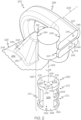
FIG. 2 is an exploded perspective view of the turbocharger system according to example embodiments not falling within the scope of the claims, wherein a valve member is oriented in a first position; -
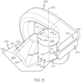
FIG. 3 is a perspective view of the turbocharger system ofFIG. 2 , wherein the valve member is disposed in a second position; -
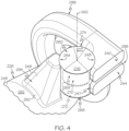
FIG. 4 is a perspective view of the turbocharger system ofFIG. 2 , wherein the valve member is disposed in a third position; -
FIG. 5 is a schematic view of the turbocharger system according to the invention, wherein the valve member is shown in a fourth position; -
FIG. 6 is an axial view of the turbocharger system ofFIG. 5 , wherein the valve member is shown in the fourth position; -
FIG. 7 is a schematic view of the turbocharger system ofFIG. 5 , wherein the valve member is shown in the first position; -
FIG. 8 is a schematic view of the turbocharger system ofFIG. 5 , wherein the valve member is shown in the second position; and -
FIG. 9 is a schematic view of the turbocharger system ofFIG. 5 , wherein the valve member is shown in the third position. - The following detailed description is merely exemplary in nature and is not intended to limit the present disclosure or the application and uses of the present disclosure. Furthermore, there is no intention to be bound by any theory presented in the preceding background or the following detailed description.
- Broadly, example embodiments disclosed herein include a turbocharger system with improved characteristics. In particular, example embodiments include a turbocharger system with at least two volute members (e.g., scrolls). The volute members direct exhaust gas flow toward a turbine wheel. The system also includes a bypass structure (i.e., waste gate), which directs exhaust gas to bypass the turbine wheel. The turbocharger system also includes a valve member that is moveable (e.g., rotatable) between different positions to vary the flow between the volute members and the bypass structure. The valve member may be precisely controlled for movement between these various positions. Accordingly, the turbocharger system may provide engine boost at a wide variety of operating conditions.
- Furthermore, the valve member may include other features that provide various advantages. The valve member is oriented such that its rotational axis is oriented transverse to the flow axis of the twin scroll structures. The valve member is partly received in the first scroll structure and partly received in the second scroll structure. Accordingly, forces may be distributed substantially evenly across the valve member during operation for effective and accurate controlled movement of the valve member. This configuration may reduce vibration and/or other sources of noise during operation of the turbocharger system. Furthermore, this arrangement may cause the turbocharger system to be relatively compact. The valve member has a relatively simple shape, namely a cylindrical shape. Accordingly, the valve member may be highly manufacturable. The turbocharger system of the present application may also improve catalyst lightening. Additional details of the present disclosure will be discussed below.
-
FIG. 1 is a schematic view of anexample turbocharger system 100 that includes aturbocharger housing 101 and arotor 102. Therotor 102 is configured to rotate within theturbocharger housing 101 about an axis 103 (axis of rotor rotation). Therotor 102 may be supported for rotation about theaxis 103 via one or more bearings (not shown). In some embodiments, therotor 102 may be rotationally supported by thrust bearings and a plurality of journal bearings. Alternatively, other bearings may be included. - As shown in the illustrated embodiment, the
turbocharger housing 101 may include aturbine housing 105, acompressor housing 107, and a bearing housing 109. The bearing housing 109 may be disposed between the turbine andcompressor housings rotor 102. - Additionally, the
rotor 102 includes aturbine wheel 111, acompressor wheel 113, and ashaft 115. Theturbine wheel 111 is located substantially within theturbine housing 105. Thecompressor wheel 113 is located substantially within thecompressor housing 107. Theshaft 115 extends along theaxis 103, through the bearing housing 109, to connect theturbine wheel 111 to thecompressor wheel 113. Accordingly, theturbine wheel 111 and thecompressor wheel 113 may rotate together about theaxis 103. - The
turbine housing 105 and theturbine wheel 111 cooperate to form a turbine (i.e., turbine section, turbine stage) configured to circumferentially receive a high-pressure and high-temperatureexhaust gas stream 121 delivered from an upstream exhaust structure 191 (e.g., one or more upstream exhaust pipes) extending from anexhaust manifold 123 of aninternal combustion engine 125. The turbine wheel 111 (and thus the rotor 102) is driven in rotation around theaxis 103 by the high-pressure and high-temperatureexhaust gas stream 121. Theturbine housing 105 is also connected to a downstream exhaust structure 126 (e.g., one or more downstream exhaust pipes). Theturbine housing 105 releases anexhaust gas stream 127 thereto. Theexhaust gas stream 127 can be lower-pressure and lower-temperature compared to theexhaust gas stream 121. - The
turbocharger system 100 further includes a bypass structure 194 (i.e., a waste gate). Thebypass structure 194 may extend from thedownstream exhaust structure 126 and defines a passage therein that is fluidly connected to the passage within thedownstream exhaust structure 126. As will be discussed, thebypass structure 194 allows exhaust gas from theupstream exhaust structure 191 to bypass theturbine wheel 111 and flow into thedownstream exhaust structure 126. - Also, the
turbine housing 105 includes one or more structures that define distinct flow passages for exhaust gas delivered by theupstream exhaust structure 191. As shown schematically in the embodiment ofFIG. 1 , theturbine housing 105 includes afirst structure 196 and asecond structure 198. As will be discussed, the first and/orsecond structures axis 103 and about theturbine wheel 111. As such, the first andsecond structures turbine housing 105. It will be appreciated that theturbine housing 105 may include more than two volute structures without departing from the scope of the present disclosure. - In some embodiments, the
first structure 196 may be connected to a firstupstream exhaust pipe 193 of theupstream exhaust structure 191, and thesecond structure 198 may be connected to asecond exhaust pipe 195 of theupstream exhaust structure 191. Thefirst exhaust pipe 193 and thesecond exhaust pipe 195 may be connected to different combustion chambers of theengine 125. Thus, rotation of theturbine wheel 111 is unlikely to be negatively affected by different pulse flow conditions of the exhaust gas flowing through theupstream exhaust structure 191. - The
compressor housing 107 andcompressor wheel 113 cooperate to form a compressor (i.e., compressor section, compressor stage). Thecompressor wheel 113, being driven in rotation by the exhaust-gas driventurbine wheel 111, is configured to compress received input air 131 (e.g., ambient air, or already-pressurized air from a previous-stage in a multi-stage compressor) into apressurized air stream 133 that is ejected circumferentially from thecompressor housing 107. Thecompressor housing 107 may have a shape (e.g., a volute shape or otherwise) configured to direct and pressurize the air blown from thecompressor wheel 113. Due to the compression process, the pressurized air stream is characterized by an increased temperature, over that of theinput air 131. - The
air stream 133 may be channeled through an air cooler 135 (i.e., an intercooler), such as a convectively cooled charge air cooler. Theair cooler 135 may be configured to dissipate heat from theair stream 133, increasing its density. The resulting cooled andpressurized air stream 137 is channeled into anintake manifold 139 of theinternal combustion engine 125, or alternatively, into a subsequent-stage, in-series compressor. The operation of the system may be controlled by an ECU 151 (engine control unit) that connects to the remainder of the system viacommunication connections 153. - The
turbocharger system 100 further includes avalve structure 190. Generally, thevalve structure 190 regulates and varies flow of exhaust between thefirst structure 196, thesecond structure 198, and thebypass structure 194. Thevalve structure 190 moves between various positions to regulate and vary the flow between the various structures as will be discussed in detail below. - The
valve structure 190 has at least one position that allows at least some of thegas stream 121 to flow through the first and/orsecond structures turbine housing 105 to turn theturbine wheel 111 and to flow to thedownstream exhaust structure 126. Thevalve structure 190 also has at least one position that allows at least some of thegas stream 121 to flow through thebypass structure 194 to thedownstream exhaust structure 126, bypassing theturbine wheel 111 in the process. Additionally, thevalve structure 190 has at least one position that allows at least some of thegas stream 121 to flow between the first andsecond structures turbine housing 105. - In some embodiments, the
valve structure 190 may be actuated between its various positions by anactuator 192. Theactuator 192 may be of any suitable type, such as an electric actuator, a hydraulic actuator, or a pneumatic actuator. - The
actuator 192 may be connected to and controlled by theECU 151. TheECU 151 may also include aprocessor 199, which is connected to one ormore sensors 189. Thesensor 189 may be configured to detect various conditions relating to theturbocharger system 100. In some embodiments, for example, thesensor 189 may detect various conditions related to the operation of the engine 125 (e.g., engine speed, exhaust gas mass flow output, etc.). Thesensor 189 may provide signals to theprocessor 199 that correspond to the detected condition(s). Theprocessor 199 may, in turn, generate control signals for theactuator 192 for moving thevalve structure 190 according to the conditions detected by thesensor 189. Accordingly, the position of the valve structure 190 (and, thus, flow of theexhaust gas stream 121 relative to the turbocharger system 100) may be controlled. This, in turn, may allow control of the speed of thecompressor wheel 113, the mass flow of theair stream 133, etc. - It will be appreciated that the
turbocharger system 100 and thevalve structure 190 may be arranged and configured differently from the embodiment ofFIG. 1 . Moreover, it will be appreciated thatFIG. 1 schematically illustrates theturbocharger system 100, thevalve structure 190, theIC engine 125, and other components. Therefore, these components are not necessarily drawn to scale. - Referring now to
FIGS. 2-4 , aturbocharger system 200 not falling within the scope of the claims will be discussed according to example embodiments. Theturbocharger system 200 may include similar features to those discussed above in relation toFIG. 1 . The description of features described above will not be repeated for purposes of brevity. Components that correspond to those ofFIG. 1 are indicated inFIGS. 2-4 with corresponding reference numbers increased by 100. - The
turbocharger system 200 includes thefirst volute structure 296 and thesecond volute structure 298. Thefirst volute structure 296 and thesecond volute structure 298 may be disposed in a twin scroll arrangement. - The
first volute structure 296 is a volute structure with afirst volute passage 240 defined therein. Thefirst volute passage 240 extends along a first axis 241 about theaxis 203 of rotation of the turbine wheel. (The turbine wheel is hidden inFIGS. 2-4 but may be configured similar to theturbine wheel 111 ofFIG. 1 ). Thefirst volute passage 240 may include aninlet segment 242, and thefirst volute passage 240 may extend in a downstream direction along the first axis 241. The first axis 241 may be substantially straight along theinlet segment 242; however, the first axis 241 may spiral about theaxis 203 further downstream in thefirst volute passage 240. Also, the cross sectional area of the first volute passage 240 (taken normal to the axis 241) may be larger than the cross sectional area further downstream. - Furthermore, the
first volute structure 296 may include afirst branch aperture 243. Thefirst branch aperture 243 may be an opening, hole, or other aperture extending through the wall of thefirst volute structure 296 in theinlet segment 242. Thefirst branch aperture 243 may have a variety of shapes and may be disposed in various locations on thefirst volute structure 296 without departing from the scope of the present disclosure. - Likewise, the
second volute structure 298 is a volute structure with asecond volute passage 244 defined therein. Thesecond volute passage 244 extends along asecond axis 245 about theaxis 203 of rotation of the turbine wheel. Thesecond volute passage 244 may include an inlet segment 246, which is substantially similar to theinlet segment 242 of thefirst volute passage 240. - Furthermore, the
second volute structure 298 may include asecond branch aperture 247. Thesecond branch aperture 247 may be an opening, hole, or other aperture extending through the wall of thesecond volute structure 298 in the inlet segment 246. Thesecond branch aperture 247 may have a variety of shapes and may be disposed in various locations on thesecond volute structure 298 without departing from the scope of the present disclosure. - As shown, the first and
second structures turbine housing 105 ofFIG. 1 ) may define both the first andsecond structures 296, 298 (and, thus, both the first andsecond volute passages 240, 244). Also, it will be appreciated that thefirst volute structure 296 may be attached to an upstream exhaust pipe (such as theupstream exhaust pipe 193 ofFIG. 1 ) with theinlet segment 242 of thefirst volute passage 240 fluidly connected to receive exhaust gas therefrom. Likewise, thesecond volute structure 298 may be attached to another upstream exhaust pipe (such as theupstream exhaust pipe 195 ofFIG. 1 ) with the inlet segment 246 fluidly connected to receive exhaust gas therefrom. - As shown in
FIG. 2 , thedownstream exhaust structure 226 may extend generally parallel to theaxis 203. Theexhaust structure 226 may be a hollow, elongate pipe that defines adownstream exhaust passage 248 therein. - The
bypass structure 294 may be a thin-walled and hollow structure that defines abypass passage 249 therein. In some embodiments, thebypass structure 294 may have a shape that is frusto-conic or that resembles a truncated pyramid. A base 250 may be attached to anouter surface 252 of thedownstream exhaust structure 226, and thebypass structure 294 may project radially from theouter surface 252. Thebypass structure 294 may also taper such that the cross sectional area gradually reduces as thebypass structure 294 extends further away from thesurface 252. The hollowinterior bypass passage 249 may be in fluid communication with thedownstream exhaust passage 248, proximate thebase 250. In other words, thebypass passage 249 may be open to thedownstream exhaust passage 248 proximate thebase 250. Furthermore, thebypass structure 294 may include a bypass aperture 254 (i.e., a bypass passage inlet). Thebypass aperture 254 may be an opening, a hole, a slot, or other aperture. Thebypass aperture 254 may be disposed along a side of thebypass structure 294. As will be discussed, at least part of a bypass flow path may be defined from thebypass aperture 254, through thebypass passage 249 toward thebase 250, and into thedownstream exhaust passage 248. - The
valve structure 290 includes avalve member 260 and may include asupport structure 261. Thesupport structure 261 may be hollow and generally cylindrical in some embodiments. Also, thesupport structure 261 may be fixedly attached to thebypass structure 294, thefirst volute structure 296, and/or thesecond volute structure 298. Thevalve member 260 is supported for movement relative to thesupport structure 261 and, thus, supported for movement relative to thebypass structure 294, thefirst volute structure 296, and thesecond volute structure 298. Thevalve member 260 is supported for rotation about alongitudinal axis 262. Thevalve member 260 is oriented such that theaxis 262 extends transverse to the incoming flow into thevolute passage 240 and thesecond volute passage 244. In some embodiments, for example, theaxis 262 may be substantially perpendicular to the axis 241 of thefirst volute passage 240 and theaxis 245 of thesecond volute passage 244. - The
valve member 260 is shown exploded from thesupport structure 261 for clarity inFIG. 2 . Thevalve member 260 is generally cylindrical and hollow. Thevalve member 260 includes anouter wall 266 that defines the outer and inner surfaces of thevalve member 260. In some embodiments, theouter wall 266 may be a unitary, one-piece member. In other embodiments, theouter wall 266 may be assembled from a plurality of parts. - The
outer wall 266 comprises afirst end member 263, asecond end member 264, and aside member 265 that extends along theaxis 262 between the first andsecond end members first end member 263 may be disposed proximate afirst end 267 of thevalve member 260, and thesecond end member 264 may be disposed proximate asecond end 268 of thevalve member 260. Accordingly, the first andsecond end members axis 262 with theaxis 262 extending through both. Theside member 265 encircles theaxis 262 annularly in a circumferential direction. In some embodiments, the first and/orsecond end members 263, 264 (as well as the cross section of the side member 265) are substantially circular. Also, in some embodiments, the first andsecond end members side member 265 may be centered with respect to theaxis 262. Accordingly, theouter wall 266 of thevalve member 260 has a shape corresponding to a right circular cylinder. - In some embodiments, the
outer wall 266 defines one ormore valve passages 269 within thevalve member 260. As shown in the embodiment ofFIG. 2 , for example, the valve member may include asingle valve passage 269, which comprises the hollow interior of thevalve member 260 as defined by the inner surfaces of theouter wall 266. Also, as shown, theouter wall 266 may have a wall thickness that is substantially constant; therefore, thevalve passage 269 may define a cylindrical volumetric space. However, it will be appreciated that thevalve member 260 may include internal surface features, contoured surfaces, channels, and the like such that thevalve passage 269 may have a variety of shapes without departing from the scope of the present disclosure. Also, as will be discussed in detail below, thevalve member 260 may include more than onedistinct valve passage 269 without departing from the scope of the present disclosure. - The
valve member 260 may further include one or more first apertures, namely anupper aperture 270 and alower aperture 272 that extend radially through theside member 265 of theouter wall 266 to provide access into thevalve passage 269. Theupper aperture 270 may be disposed proximate thefirst end 267 of thevalve member 260, and thelower aperture 272 may be disposed proximate thesecond end 268 of thevalve member 260. In some embodiments, the upper andlower apertures lower apertures lower apertures - Furthermore, the
valve member 260 may include asecond aperture 274. Thesecond aperture 274 may extend radially through theside member 265 of theouter wall 266 to provide access out of thevalve passage 269. Thesecond aperture 274 may extend between both thefirst end 267 and thesecond end 268 of thevalve member 260. In some embodiments, thesecond aperture 274 may be substantially rectangular in shape; however, it will be appreciated that the shape of thesecond aperture 274 may have any suitable shape and size without departing from the scope of the present disclosure. - In some embodiments, the upper and
lower apertures first sector 276 of thevalve member 260 with respect to theaxis 262. Thesecond aperture 274 may be disposed within asecond sector 277 of thevalve member 260 with respect to theaxis 262. As shown inFIG. 2 , thefirst sector 276 may be defined between a firstradial plane 275 and a secondradial plane 278. Meanwhile, thesecond sector 277 may be defined between a thirdradial plane 273 and a fourthradial plane 279. In some embodiments, thefirst sector 276 may be larger (as measured in the circumferential direction about the axis 262) than thesecond sector 277. As will be discussed, thevalve member 260 may be supported for rotation relative to the first andsecond volute structures bypass structure 294. Rotation of thevalve member 260 rotates the first andsecond sectors 276, 277 (and, thus, rotates theapertures structures turbocharger system 100 in a controlled manner. - The
valve member 260 may be received within thesupport structure 261. Also, at least part of thefirst end 267 of thevalve member 260 may be received within theinlet segment 242 of thefirst volute passage 240. As such, a sector of thefirst end 267 of thevalve member 260 may be exposed within theinlet segment 242. Likewise, at least part of thesecond end 268 of thevalve member 260 may be received within the inlet segment 246 of thesecond volute passage 244. As such, a sector of thesecond end 268 of thevalve member 260 may be exposed within the inlet segment 246. Moreover, a sector of thevalve member 260 may be received and exposed within thebypass passage 249. - The
support structure 261 may support thevalve member 260 for rotation about theaxis 262. For example, the outer surface of theouter wall 266 may slide on the inner surface of thesupport structure 261 as thevalve member 260 rotates about theaxis 262. As thevalve member 260 rotates, different sectors of thevalve member 260 may exposed within theinlet segment 242 of thefirst volute passage 240, the inlet segment 246 of thesecond volute passage 244, and thebypass passage 249. - Operation of the
turbocharger system 100 will now be discussed with reference toFIGS. 2 ,3 , and4 . As mentioned, thevalve member 260 may rotate about theaxis 262 to vary flow through theturbocharger system 100. In some embodiments, thevalve member 260 may rotate between at least three positions: the first position represented inFIG. 2 , the second position represented inFIG. 3 , and the third position represented inFIG. 4 . In some embodiments, thevalve member 260 may also rotate to one or more additional intermediate positions to progressively change the amount of open area of theupper aperture 270, thelower aperture 272, and thesecond aperture 274 relative to thefirst branch aperture 243, thesecond branch aperture 247, and thebypass aperture 274, respectively. Thevalve member 260 may be rotated by an actuator (such as theactuator 192 ofFIG. 1 ). Also, rotation of thevalve member 260 may be controlled by an ECU (such as theECU 151 ofFIG. 1 ) based at least partly on condition(s) detected by a sensor (such as thesensor 189 ofFIG. 1 ). - In the first position represented in
FIG. 1 , theupper aperture 270 of thevalve member 260 may be at least partly aligned with (i.e., in fluid communication with) thefirst branch aperture 243 of thefirst volute passage 240. Likewise, thelower aperture 272 may be at least partly aligned with thesecond branch aperture 247 of thesecond volute passage 244. Furthermore, thesecond aperture 274 of thevalve member 260 may be at least partly aligned with thebypass aperture 254 of thebypass structure 294. In this position, a first volute flow path may be established, allowing exhaust gas to flow through thefirst volute passage 240 along the axis 241 toward the turbine wheel. Also, a second volute flow path may be established, allowing exhaust gas to flow through thesecond volute passage 244, along theaxis 245 toward the turbine wheel. Additionally, thevalve passage 269 may, in this position, provide a cross flow path, wherein exhaust gas may flow between the first andsecond volute passages upper aperture 270 and thelower aperture 272. Moreover, in this first position, thevalve passage 269 may provide a bypass flow path, wherein exhaust gas may flow from thefirst volute passage 240 and/or thesecond volute passage 244 to thebypass passage 249 via theupper aperture 270, thelower aperture 272, and thesecond aperture 274. - In the second position represented in
FIG. 3 , theupper aperture 270 of thevalve member 260 may be at least partly aligned with (i.e., in fluid communication with) thefirst branch aperture 243 of thefirst volute passage 240. Likewise, thelower aperture 272 may be at least partly aligned with thesecond branch aperture 247 of thesecond volute passage 244. However, thesecond aperture 274 of thevalve member 260 may be misaligned with thebypass aperture 254, and instead theouter wall 266 of thevalve member 260 may cover over thebypass aperture 254. Thus, thevalve passage 269 of thevalve member 260 may provide the cross flow path, allowing exhaust gas to flow between the first andsecond volute passages FIG. 2 . However, theouter wall 266 of thevalve member 260 may block flow to thebypass passage 249 and substantially prevent flow along the bypass flow path. - In the third position represented in
FIG. 4 , theupper aperture 270 may be misaligned with thefirst branch aperture 243, and thelower aperture 272 may be misaligned with thesecond branch aperture 247. As such, theouter wall 266 may block the first andsecond branch apertures second aperture 274 may be misaligned with thebypass aperture 254, and instead, theouter wall 266 may block thebypass aperture 254. Accordingly, in the position ofFIG. 4 , theouter wall 266 of thevalve member 260 may prevent flow along the cross flow path (i.e., flow between the first andsecond volute passages 240, 244). Likewise, theouter wall 266 of thevalve member 260 may prevent flow along the bypass flow path (i.e., flow from the first and/orsecond volute passages - It will be appreciated that the shape, size, dimension, orientation, and/or position of the
upper aperture 270, thelower aperture 272, and thesecond aperture 274 may be configured to provide a desired flow characteristic at one or more angular positions of thevalve member 260. For example, as shown inFIG. 3 , part of theupper aperture 270 may be aligned with thefirst branch aperture 243 and part of thelower aperture 272 may be aligned with thesecond branch aperture 247. Other parts of the upper andlower apertures second branch apertures FIG. 2 , wherein a majority of theupper aperture 270 aligns with thefirst branch aperture 243 and a majority of thelower aperture 272 aligns with thesecond branch aperture 247. Because of this contrast, the mass flow capacity between the first andsecond volute passages FIG. 2 may be greater than the mass flow capacity in the position ofFIG. 3 . Accordingly, by rotating thevalve member 260, the mass flow capacity may be changed and controlled for one or more of the various flow paths of theturbocharger system 100. - Thus, the
valve member 260 may be controlled for movement between these various positions (and to positions therebetween) according to current operating conditions. The amount of open, exposed area of theupper aperture 270, thelower aperture 272, and thesecond aperture 274 may vary as thevalve member 260 is rotated to alter flow along the various flow paths. The flow through theturbocharger system 100 may be controlled with precision. Accordingly, engine boost may be provided at a wide variety of operating conditions. Furthermore, forces on the valve member 160 may be distributed fairly evenly across the valve member 160 during operation for effective and accurate controlled movement. Vibration and/or other sources of noise may be reduced as well. Furthermore, theturbocharger system 100 may be relatively compact. Additionally, in some embodiments, the valve member 160 may have a relatively simple, cylindrical shape, which is highly manufacturable. - Referring now to
FIGS. 5-9 aturbocharger system 300 according to the invention is illustrated according to additional embodiments. Theturbocharger system 300 may be substantially similar to the embodiment ofFIGS. 2-4 except as noted below. Components that correspond to those ofFIGS. 2-4 are indicated with corresponding reference numbers increased by 100. - Referring initially to
FIGS. 5 and6 , thevalve member 360 is substantially cylindrical, similar to the embodiments discussed above. Thevalve member 360 includes a plurality of valve passages therein, which are illustrated schematically. The valve passages include afirst valve passage 380, asecond valve passage 381, and athird valve passage 382. Thevalve passages axis 362 and are separated (i.e., fluidly disconnected) from each other by at least onedivider wall 384. - The
first valve passage 380 may include afirst bypass opening 385. Thesecond valve passage 381 may include asecond bypass opening 386. Thethird valve passage 382 may include two or morecross flow openings 387, one of which is in fluid communication with thefirst volute passage 340 and the other of which is in fluid communication with thesecond volute passage 344. The first, second, andthird openings valve member 360 with respect to theaxis 362. - Additionally, as shown in
FIG. 6 , thevalve member 360 may include one or moresecond apertures 374. As shown, thesecond apertures 374 may be disposed on thefirst end 367 of thevalve member 360. In some embodiments, onesecond aperture 374 may be fluidly connected to thefirst valve passage 380, and anothersecond aperture 374 may be fluidly connected to thesecond valve passage 381. Thesesecond apertures 374 may be fluidly connected to thebypass passage 349. - The
valve member 360 is arranged with respect to the volute structures 396, 398 such that theaxis 362 extends transverse (e.g., normal) to the incoming flow into thevolute passage 340 and thesecond volute passage 344. Thefirst end 367 is received and exposed within thefirst volute passage 340, and thesecond end 368 is received and exposed within the second volute passage 344 (FIG. 6 ). Also, rotation of thevalve member 360 may change the exposed area of thevalve member 360 within thevolute passages - The
valve member 360 rotates to provide one or more of the flow paths described above in relation toFIGS. 2-4 . Also, thevalve member 360 may provide additional flow characteristics. - When in the position of
FIG. 5 and6 , for example, the first opening 385 (and thus the first valve passage 380) is fluidly connected to thefirst volute passage 340, and the second opening 386 (and thus the second valve passage 381) is fluidly connected to thesecond volute passage 344. Thefirst valve passage 380 provides a first bypass flow path from thefirst volute passage 340 to thebypass passage 349. Also, thesecond valve passage 380 may provide a second bypass flow path from thesecond volute passage 344 to thebypass passage 349. It will be appreciated that thevalve member 360 may maintain the first and second bypass flow paths fluidly distinct (i.e., fluidly disconnected from each other). - The
valve member 360 may also rotate to the position ofFIG. 7 . In this position, thethird opening 387 to thethird valve passage 382 is exposed to thevolute passage 340, allowing cross flow between the first andsecond volute passages openings second valve passages second volute passages FIG. 7 may correspond to the configuration ofFIG. 2 . - Additionally, in the position of
FIG. 8 , thethird opening 387 is exposed, allowing cross flow between the first andsecond volute passages second openings volute passages FIG. 8 may correspond to the configuration ofFIG. 3 . - Moreover, in the position of
FIG. 9 , theopenings volute passages volute passages volute passages bypass passage 349 is substantially prevented. - While at least one exemplary embodiment has been presented in the foregoing detailed description, it should be appreciated that a vast number of variations exist. It should also be appreciated that the exemplary embodiment or exemplary embodiments are only examples, and are not intended to limit the scope, applicability, or configuration of the present disclosure in any way. Rather, the foregoing detailed description will provide those skilled in the art with a convenient road map for implementing an exemplary embodiment of the present disclosure. It is understood that various changes may be made in the function and arrangement of elements described in an exemplary embodiment without departing from the scope of the present disclosure as set forth in the appended claims.
Claims (7)
- A turbocharger system comprising:a turbine section with a turbine wheel (111), a first volute structure (296) with a first volute passage (240) that extends along a first axis, and a second volute structure (298) with a second volute passage (244) that extends along a second axis, the first volute passage configured to direct flow of exhaust gas toward the turbine wheel, the second volute passage configured to direct flow of exhaust gas toward the turbine wheel;a downstream exhaust structure (126) with a downstream exhaust passage (248) configured to receive exhaust gas from the turbine section;a bypass structure (194) with a bypass passage (249) configured to provide exhaust gas that bypasses the turbine wheel to the downstream exhaust passage; anda valve member (260) having an outer wall (266) comprising a first end member (263), a second end member (264) and a side member (265) that extends along an axis (262) between the first and second end members and encircles the axis, the outer wall (266) defining outer and inner surfaces of the valve member (260), the valve member (260) being substantially cylindrical and hollow, wherein the valve member includes a first portion and a second portion that are separated along the axis of rotation and wherein the first portion is at least partially received within the first volute passage (240) and the second portion is at least partially received within the second volute passage (244), the valve member being supported for rotation about an axis of rotation between a first position, a second position, and a third position, wherein the outer wall (266) of the valve member (260) includes a plurality of valve passages (380, 381, 382) separated by at least one divider (384), the plurality of valve passages having a respective aperture (385, 386, 387) open at the side member (265);wherein the axis of rotation is oriented transverse to the first axis and the second axis;wherein the plurality of valve passages, with the valve member in the first position, provides a cross flow path between the first volute passage (240) and the second volute passage (244) and provides a bypass flow path from at least one of the first volute passage (240) and the second volute passage (244) to the bypass passage (249);wherein the plurality of valve passages, with the valve member in the second position, provides the cross flow path;wherein the valve member, in the second position, substantially prevents flow along the bypass flow path;wherein the valve member, in the third position, substantially prevents flow along the cross flow path and the bypass flow path;wherein the plurality of valve passages includes:a first valve passage (382) that provides the cross flow path with the valve member in the first position; anda second valve passage (380) that provides the bypass flow path with the valve member in the first position.
- The turbocharger system of claim 1, wherein one of the first volute passage (240) and the second volute passage (244) includes a segment;wherein a first opening to the first valve passage is included in a first sector of the valve member (260) with respect to the axis of rotation;wherein a second opening to the second valve passage is included in a second sector of the valve member;wherein the valve member includes an exposed area that is exposed to the segment and an unexposed area that is unexposed to the segment;wherein the first opening and the second opening are included in the exposed area when the valve member is in the first position;wherein the first opening is included in the exposed area and the second opening is included in the unexposed area when the valve member is in the second position; andwherein the first opening and the second opening are included in the unexposed area when the valve member is in the third position.
- The turbocharger system of claim 1 or 2, wherein the first valve passage is separated from the second valve passage by the at least one divider (384);wherein the plurality of valve passages includes a third valve passage (381) that is separated from the second valve passage (380) by the at least one divider (384);wherein the valve member (260) is supported for rotation about the axis of rotation between the first position, the second position, the third position, and a fourth position;wherein the valve member, with the valve member in the fourth position, substantially prevents flow along the cross flow path; andwherein the second valve passage provides a first bypass flow path from the first volute passage to the bypass passage; andwherein the third valve passage provides a second bypass flow path from the second volute passage to the bypass passage.
- The turbocharger of any preceding claim, further comprising:an actuator (192) configured to actuate the valve member between the first position, the second position, and the third position;a sensor (189) configured to detect a condition related to operation of the turbocharger system; anda controller configured to control the actuator based at least partly on the condition detected by the sensor.
- The turbocharger system of claim 4, wherein the sensor (189) is configured to sense at least one of an engine speed and / or an exhaust gas mass flow output of an engine configured to provide exhaust gas to the first volute passage and the second volute passage, and wherein the controller is configured to control the actuator based at least partly on the detected at least one of the engine speed and the exhaust gas mass flow output.
- The turbocharger system of any preceding claim, wherein the axis of rotation is oriented substantially normal to the first axis and the second axis.
- The turbocharger system of claim 1, wherein the plurality of valve passages includes a third valve passage (381);wherein the second valve passage provides a first bypass flow path from the first volute passage to the bypass passage with the valve member in the first position; andwherein the third valve passage provides a second bypass flow path from the second volute passage to the bypass passage with the valve member in the first position.
Applications Claiming Priority (2)
| Application Number | Priority Date | Filing Date | Title |
|---|---|---|---|
| US15/592,504 US10677150B2 (en) | 2017-05-11 | 2017-05-11 | Rotatable valve for turbocharger system with plural volute members |
| EP18171664.8A EP3401528B1 (en) | 2017-05-11 | 2018-05-09 | Turbocharger system |
Related Parent Applications (2)
| Application Number | Title | Priority Date | Filing Date |
|---|---|---|---|
| EP18171664.8A Division EP3401528B1 (en) | 2017-05-11 | 2018-05-09 | Turbocharger system |
| EP18171664.8A Division-Into EP3401528B1 (en) | 2017-05-11 | 2018-05-09 | Turbocharger system |
Publications (2)
| Publication Number | Publication Date |
|---|---|
| EP3667045A1 EP3667045A1 (en) | 2020-06-17 |
| EP3667045B1 true EP3667045B1 (en) | 2023-07-19 |
Family
ID=62148266
Family Applications (2)
| Application Number | Title | Priority Date | Filing Date |
|---|---|---|---|
| EP20156647.8A Active EP3667045B1 (en) | 2017-05-11 | 2018-05-09 | Turbocharger system with plural volute members and a rotatable valve |
| EP18171664.8A Active EP3401528B1 (en) | 2017-05-11 | 2018-05-09 | Turbocharger system |
Family Applications After (1)
| Application Number | Title | Priority Date | Filing Date |
|---|---|---|---|
| EP18171664.8A Active EP3401528B1 (en) | 2017-05-11 | 2018-05-09 | Turbocharger system |
Country Status (3)
| Country | Link |
|---|---|
| US (2) | US10677150B2 (en) |
| EP (2) | EP3667045B1 (en) |
| CN (1) | CN108869010B (en) |
Families Citing this family (10)
| Publication number | Priority date | Publication date | Assignee | Title |
|---|---|---|---|---|
| EP3486450B1 (en) * | 2017-11-15 | 2025-07-16 | Perkins Engines Company Limited | An exhaust flow control valve with integrated wastegate |
| EP3696387B1 (en) | 2019-02-15 | 2021-09-29 | Borgwarner Inc. | Dual volute turbocharger and system including the same |
| US11408333B2 (en) | 2019-02-15 | 2022-08-09 | Borgwarner Inc. | Valve assembly for a dual volute turbocharger and dual volute turbocharger including the same |
| EP3696393B1 (en) * | 2019-02-15 | 2023-05-17 | Borgwarner Inc. | Method of controlling a valve of a dual volute turbocharger |
| CN111663968B (en) * | 2019-03-08 | 2025-04-01 | 博格华纳公司 | Turbine housing, multi-channel turbine and multi-channel turbocharger |
| CN110578562B (en) * | 2019-08-30 | 2023-08-29 | 上海齐耀动力技术有限公司 | Cooling structure and connection structure thereof |
| DE102021203406A1 (en) | 2021-04-07 | 2022-10-13 | Vitesco Technologies GmbH | Turbocharger device for an exhaust gas turbocharger with wastegate |
| US11492965B1 (en) | 2021-08-31 | 2022-11-08 | Garrett Transportation I Inc. | Turbocharger turbine rotary bypass valve providing waste gate regulation and full turbine bypass functions |
| DE102022000150B4 (en) | 2022-01-17 | 2024-05-23 | Mercedes-Benz Group AG | Turbine for an exhaust gas turbocharger, in particular of a motor vehicle, and internal combustion engine |
| US12071888B2 (en) * | 2022-12-23 | 2024-08-27 | Garrett Transportation I Inc. | Turbine housing and manifold assembly with control valve |
Family Cites Families (17)
| Publication number | Priority date | Publication date | Assignee | Title |
|---|---|---|---|---|
| US4177006A (en) | 1977-09-29 | 1979-12-04 | The Garrett Corporation | Turbocharger control |
| US4526004A (en) * | 1983-10-25 | 1985-07-02 | Holset Engineering Company Limited | Exhaust brake valve |
| DE19618160C2 (en) | 1996-05-07 | 1999-10-21 | Daimler Chrysler Ag | Exhaust gas turbocharger for an internal combustion engine |
| DE10258022A1 (en) * | 2002-12-12 | 2004-06-24 | Daimlerchrysler Ag | Internal combustion engine with supercharger, e.g. for vehicle, has valve device in form of rotary slide valve |
| DE10303777A1 (en) * | 2003-01-31 | 2004-08-12 | Daimlerchrysler Ag | Internal combustion engine with exhaust gas turbocharger has valve body with 2 separate different openings for communicating with exhaust gas line blow-out opening in first and second open positions |
| DE102004034070A1 (en) * | 2004-07-15 | 2006-02-09 | Daimlerchrysler Ag | Internal combustion engine with an exhaust gas turbocharger |
| DE102004039927A1 (en) * | 2004-08-18 | 2006-02-23 | Daimlerchrysler Ag | Internal combustion engine with an exhaust gas turbocharger and an exhaust gas recirculation device |
| DE102004055571A1 (en) * | 2004-11-18 | 2006-06-08 | Daimlerchrysler Ag | Exhaust gas turbocharger for an internal combustion engine |
| DE102006009298A1 (en) * | 2006-03-01 | 2007-09-06 | Daimlerchrysler Ag | Internal combustion engine with an exhaust gas turbocharger |
| US8196403B2 (en) | 2008-07-31 | 2012-06-12 | Caterpillar Inc. | Turbocharger having balance valve, wastegate, and common actuator |
| CN102619617A (en) * | 2012-02-29 | 2012-08-01 | 康跃科技股份有限公司 | Multi-layer variable geometric volute device |
| US9359939B2 (en) | 2013-02-20 | 2016-06-07 | Ford Global Technologies, Llc | Supercharged internal combustion engine with two-channel turbine and method |
| US9593690B2 (en) * | 2013-06-26 | 2017-03-14 | Honeywell International Inc. | Turbocharger with an annular rotary bypass valve |
| DE112015005579B4 (en) | 2014-12-12 | 2022-05-05 | Borgwarner Inc. | TURBOCHARGER TURBINE STAGE VALVES CONTROLLED BY A SINGLE ACTUATOR |
| DE202014009873U1 (en) | 2014-12-12 | 2016-03-17 | Borgwarner Inc. | Exhaust gas turbocharger with combined adjustment device for bypass valve and flood connection |
| US9810143B2 (en) | 2015-01-16 | 2017-11-07 | Ford Global Technologies, Llc | Exhaust control valve branch communication and wastegate |
| DE112015006103T5 (en) * | 2015-02-03 | 2017-11-30 | Borgwarner Inc. | ROTATING REVERSING VALVE |
-
2017
- 2017-05-11 US US15/592,504 patent/US10677150B2/en active Active
-
2018
- 2018-05-09 EP EP20156647.8A patent/EP3667045B1/en active Active
- 2018-05-09 EP EP18171664.8A patent/EP3401528B1/en active Active
- 2018-05-10 CN CN201810443159.9A patent/CN108869010B/en active Active
-
2020
- 2020-04-28 US US16/860,310 patent/US11085366B2/en active Active
Also Published As
| Publication number | Publication date |
|---|---|
| EP3401528A1 (en) | 2018-11-14 |
| CN108869010B (en) | 2025-04-01 |
| US11085366B2 (en) | 2021-08-10 |
| CN108869010A (en) | 2018-11-23 |
| US10677150B2 (en) | 2020-06-09 |
| US20180328268A1 (en) | 2018-11-15 |
| EP3401528B1 (en) | 2020-03-18 |
| US20200256245A1 (en) | 2020-08-13 |
| EP3667045A1 (en) | 2020-06-17 |
Similar Documents
| Publication | Publication Date | Title |
|---|---|---|
| EP3667045B1 (en) | Turbocharger system with plural volute members and a rotatable valve | |
| US8585355B2 (en) | Simplified variable geometry turbocharger with sliding gate and multiple volutes | |
| CN106014492B (en) | Variable geometry nozzle for partitioned volutes | |
| US8702381B2 (en) | Simplified variable geometry turbocharger with vane rings | |
| JP4605405B2 (en) | Internal combustion engine with exhaust gas turbocharger | |
| CN102245873B (en) | Simplified variable geometry turbocharger with variable nozzle | |
| CN103180569B (en) | There is the reduced form variable geometry turbocharger of the range of flow of increase | |
| EP3301277B1 (en) | Turbocharger with ported turbine shroud | |
| EP3350418B1 (en) | A cartridge for pulse-separated variable turbine geometry turbochargers | |
| CN111148903A (en) | Radial compressor for a charging device of an internal combustion engine having an iris diaphragm arrangement, charging device and vane of an iris diaphragm arrangement | |
| WO2001014707A1 (en) | Turbocharger incorporating an integral pump for exhaust gas recirculation | |
| CN105587403B (en) | Exhaust turbochargers and internal combustion engines | |
| US10240478B2 (en) | Turbine with variable inlet cross-sectional area | |
| EP1866534A1 (en) | Variable flow turbocharger | |
| EP3438430B1 (en) | Turbocharger, two-stage turbosystem, and method for controlling two-stage turbosystem | |
| US7305826B2 (en) | Axial loading management in turbomachinery | |
| WO2018200611A1 (en) | Compressor with variable compressor inlet |
Legal Events
| Date | Code | Title | Description |
|---|---|---|---|
| PUAI | Public reference made under article 153(3) epc to a published international application that has entered the european phase |
Free format text: ORIGINAL CODE: 0009012 |
|
| STAA | Information on the status of an ep patent application or granted ep patent |
Free format text: STATUS: REQUEST FOR EXAMINATION WAS MADE |
|
| 17P | Request for examination filed |
Effective date: 20200211 |
|
| AC | Divisional application: reference to earlier application |
Ref document number: 3401528 Country of ref document: EP Kind code of ref document: P |
|
| AK | Designated contracting states |
Kind code of ref document: A1 Designated state(s): AL AT BE BG CH CY CZ DE DK EE ES FI FR GB GR HR HU IE IS IT LI LT LU LV MC MK MT NL NO PL PT RO RS SE SI SK SM TR |
|
| STAA | Information on the status of an ep patent application or granted ep patent |
Free format text: STATUS: EXAMINATION IS IN PROGRESS |
|
| 17Q | First examination report despatched |
Effective date: 20221010 |
|
| GRAP | Despatch of communication of intention to grant a patent |
Free format text: ORIGINAL CODE: EPIDOSNIGR1 |
|
| STAA | Information on the status of an ep patent application or granted ep patent |
Free format text: STATUS: GRANT OF PATENT IS INTENDED |
|
| INTG | Intention to grant announced |
Effective date: 20230324 |
|
| GRAS | Grant fee paid |
Free format text: ORIGINAL CODE: EPIDOSNIGR3 |
|
| P01 | Opt-out of the competence of the unified patent court (upc) registered |
Effective date: 20230424 |
|
| GRAA | (expected) grant |
Free format text: ORIGINAL CODE: 0009210 |
|
| STAA | Information on the status of an ep patent application or granted ep patent |
Free format text: STATUS: THE PATENT HAS BEEN GRANTED |
|
| AC | Divisional application: reference to earlier application |
Ref document number: 3401528 Country of ref document: EP Kind code of ref document: P |
|
| AK | Designated contracting states |
Kind code of ref document: B1 Designated state(s): AL AT BE BG CH CY CZ DE DK EE ES FI FR GB GR HR HU IE IS IT LI LT LU LV MC MK MT NL NO PL PT RO RS SE SI SK SM TR |
|
| REG | Reference to a national code |
Ref country code: GB Ref legal event code: FG4D |
|
| REG | Reference to a national code |
Ref country code: CH Ref legal event code: EP |
|
| REG | Reference to a national code |
Ref country code: DE Ref legal event code: R096 Ref document number: 602018053893 Country of ref document: DE |
|
| REG | Reference to a national code |
Ref country code: IE Ref legal event code: FG4D |
|
| REG | Reference to a national code |
Ref country code: LT Ref legal event code: MG9D |
|
| REG | Reference to a national code |
Ref country code: NL Ref legal event code: MP Effective date: 20230719 |
|
| REG | Reference to a national code |
Ref country code: AT Ref legal event code: MK05 Ref document number: 1589706 Country of ref document: AT Kind code of ref document: T Effective date: 20230719 |
|
| PG25 | Lapsed in a contracting state [announced via postgrant information from national office to epo] |
Ref country code: NL Free format text: LAPSE BECAUSE OF FAILURE TO SUBMIT A TRANSLATION OF THE DESCRIPTION OR TO PAY THE FEE WITHIN THE PRESCRIBED TIME-LIMIT Effective date: 20230719 |
|
| PG25 | Lapsed in a contracting state [announced via postgrant information from national office to epo] |
Ref country code: GR Free format text: LAPSE BECAUSE OF FAILURE TO SUBMIT A TRANSLATION OF THE DESCRIPTION OR TO PAY THE FEE WITHIN THE PRESCRIBED TIME-LIMIT Effective date: 20231020 |
|
| PG25 | Lapsed in a contracting state [announced via postgrant information from national office to epo] |
Ref country code: IS Free format text: LAPSE BECAUSE OF FAILURE TO SUBMIT A TRANSLATION OF THE DESCRIPTION OR TO PAY THE FEE WITHIN THE PRESCRIBED TIME-LIMIT Effective date: 20231119 |
|
| PG25 | Lapsed in a contracting state [announced via postgrant information from national office to epo] |
Ref country code: SE Free format text: LAPSE BECAUSE OF FAILURE TO SUBMIT A TRANSLATION OF THE DESCRIPTION OR TO PAY THE FEE WITHIN THE PRESCRIBED TIME-LIMIT Effective date: 20230719 Ref country code: RS Free format text: LAPSE BECAUSE OF FAILURE TO SUBMIT A TRANSLATION OF THE DESCRIPTION OR TO PAY THE FEE WITHIN THE PRESCRIBED TIME-LIMIT Effective date: 20230719 Ref country code: PT Free format text: LAPSE BECAUSE OF FAILURE TO SUBMIT A TRANSLATION OF THE DESCRIPTION OR TO PAY THE FEE WITHIN THE PRESCRIBED TIME-LIMIT Effective date: 20231120 Ref country code: NO Free format text: LAPSE BECAUSE OF FAILURE TO SUBMIT A TRANSLATION OF THE DESCRIPTION OR TO PAY THE FEE WITHIN THE PRESCRIBED TIME-LIMIT Effective date: 20231019 Ref country code: LV Free format text: LAPSE BECAUSE OF FAILURE TO SUBMIT A TRANSLATION OF THE DESCRIPTION OR TO PAY THE FEE WITHIN THE PRESCRIBED TIME-LIMIT Effective date: 20230719 Ref country code: LT Free format text: LAPSE BECAUSE OF FAILURE TO SUBMIT A TRANSLATION OF THE DESCRIPTION OR TO PAY THE FEE WITHIN THE PRESCRIBED TIME-LIMIT Effective date: 20230719 Ref country code: IS Free format text: LAPSE BECAUSE OF FAILURE TO SUBMIT A TRANSLATION OF THE DESCRIPTION OR TO PAY THE FEE WITHIN THE PRESCRIBED TIME-LIMIT Effective date: 20231119 Ref country code: HR Free format text: LAPSE BECAUSE OF FAILURE TO SUBMIT A TRANSLATION OF THE DESCRIPTION OR TO PAY THE FEE WITHIN THE PRESCRIBED TIME-LIMIT Effective date: 20230719 Ref country code: GR Free format text: LAPSE BECAUSE OF FAILURE TO SUBMIT A TRANSLATION OF THE DESCRIPTION OR TO PAY THE FEE WITHIN THE PRESCRIBED TIME-LIMIT Effective date: 20231020 Ref country code: FI Free format text: LAPSE BECAUSE OF FAILURE TO SUBMIT A TRANSLATION OF THE DESCRIPTION OR TO PAY THE FEE WITHIN THE PRESCRIBED TIME-LIMIT Effective date: 20230719 Ref country code: AT Free format text: LAPSE BECAUSE OF FAILURE TO SUBMIT A TRANSLATION OF THE DESCRIPTION OR TO PAY THE FEE WITHIN THE PRESCRIBED TIME-LIMIT Effective date: 20230719 |
|
| PG25 | Lapsed in a contracting state [announced via postgrant information from national office to epo] |
Ref country code: PL Free format text: LAPSE BECAUSE OF FAILURE TO SUBMIT A TRANSLATION OF THE DESCRIPTION OR TO PAY THE FEE WITHIN THE PRESCRIBED TIME-LIMIT Effective date: 20230719 |
|
| REG | Reference to a national code |
Ref country code: DE Ref legal event code: R097 Ref document number: 602018053893 Country of ref document: DE |
|
| PG25 | Lapsed in a contracting state [announced via postgrant information from national office to epo] |
Ref country code: ES Free format text: LAPSE BECAUSE OF FAILURE TO SUBMIT A TRANSLATION OF THE DESCRIPTION OR TO PAY THE FEE WITHIN THE PRESCRIBED TIME-LIMIT Effective date: 20230719 |
|
| PG25 | Lapsed in a contracting state [announced via postgrant information from national office to epo] |
Ref country code: SM Free format text: LAPSE BECAUSE OF FAILURE TO SUBMIT A TRANSLATION OF THE DESCRIPTION OR TO PAY THE FEE WITHIN THE PRESCRIBED TIME-LIMIT Effective date: 20230719 Ref country code: RO Free format text: LAPSE BECAUSE OF FAILURE TO SUBMIT A TRANSLATION OF THE DESCRIPTION OR TO PAY THE FEE WITHIN THE PRESCRIBED TIME-LIMIT Effective date: 20230719 Ref country code: ES Free format text: LAPSE BECAUSE OF FAILURE TO SUBMIT A TRANSLATION OF THE DESCRIPTION OR TO PAY THE FEE WITHIN THE PRESCRIBED TIME-LIMIT Effective date: 20230719 Ref country code: EE Free format text: LAPSE BECAUSE OF FAILURE TO SUBMIT A TRANSLATION OF THE DESCRIPTION OR TO PAY THE FEE WITHIN THE PRESCRIBED TIME-LIMIT Effective date: 20230719 Ref country code: DK Free format text: LAPSE BECAUSE OF FAILURE TO SUBMIT A TRANSLATION OF THE DESCRIPTION OR TO PAY THE FEE WITHIN THE PRESCRIBED TIME-LIMIT Effective date: 20230719 Ref country code: CZ Free format text: LAPSE BECAUSE OF FAILURE TO SUBMIT A TRANSLATION OF THE DESCRIPTION OR TO PAY THE FEE WITHIN THE PRESCRIBED TIME-LIMIT Effective date: 20230719 Ref country code: SK Free format text: LAPSE BECAUSE OF FAILURE TO SUBMIT A TRANSLATION OF THE DESCRIPTION OR TO PAY THE FEE WITHIN THE PRESCRIBED TIME-LIMIT Effective date: 20230719 |
|
| PLBE | No opposition filed within time limit |
Free format text: ORIGINAL CODE: 0009261 |
|
| STAA | Information on the status of an ep patent application or granted ep patent |
Free format text: STATUS: NO OPPOSITION FILED WITHIN TIME LIMIT |
|
| PG25 | Lapsed in a contracting state [announced via postgrant information from national office to epo] |
Ref country code: IT Free format text: LAPSE BECAUSE OF FAILURE TO SUBMIT A TRANSLATION OF THE DESCRIPTION OR TO PAY THE FEE WITHIN THE PRESCRIBED TIME-LIMIT Effective date: 20230719 |
|
| 26N | No opposition filed |
Effective date: 20240422 |
|
| PG25 | Lapsed in a contracting state [announced via postgrant information from national office to epo] |
Ref country code: SI Free format text: LAPSE BECAUSE OF FAILURE TO SUBMIT A TRANSLATION OF THE DESCRIPTION OR TO PAY THE FEE WITHIN THE PRESCRIBED TIME-LIMIT Effective date: 20230719 |
|
| PG25 | Lapsed in a contracting state [announced via postgrant information from national office to epo] |
Ref country code: BG Free format text: LAPSE BECAUSE OF FAILURE TO SUBMIT A TRANSLATION OF THE DESCRIPTION OR TO PAY THE FEE WITHIN THE PRESCRIBED TIME-LIMIT Effective date: 20230719 |
|
| PG25 | Lapsed in a contracting state [announced via postgrant information from national office to epo] |
Ref country code: BG Free format text: LAPSE BECAUSE OF FAILURE TO SUBMIT A TRANSLATION OF THE DESCRIPTION OR TO PAY THE FEE WITHIN THE PRESCRIBED TIME-LIMIT Effective date: 20230719 |
|
| REG | Reference to a national code |
Ref country code: CH Ref legal event code: PL |
|
| PG25 | Lapsed in a contracting state [announced via postgrant information from national office to epo] |
Ref country code: MC Free format text: LAPSE BECAUSE OF FAILURE TO SUBMIT A TRANSLATION OF THE DESCRIPTION OR TO PAY THE FEE WITHIN THE PRESCRIBED TIME-LIMIT Effective date: 20230719 |
|
| PG25 | Lapsed in a contracting state [announced via postgrant information from national office to epo] |
Ref country code: LU Free format text: LAPSE BECAUSE OF NON-PAYMENT OF DUE FEES Effective date: 20240509 |
|
| PG25 | Lapsed in a contracting state [announced via postgrant information from national office to epo] |
Ref country code: MC Free format text: LAPSE BECAUSE OF FAILURE TO SUBMIT A TRANSLATION OF THE DESCRIPTION OR TO PAY THE FEE WITHIN THE PRESCRIBED TIME-LIMIT Effective date: 20230719 Ref country code: LU Free format text: LAPSE BECAUSE OF NON-PAYMENT OF DUE FEES Effective date: 20240509 Ref country code: CH Free format text: LAPSE BECAUSE OF NON-PAYMENT OF DUE FEES Effective date: 20240531 |
|
| REG | Reference to a national code |
Ref country code: BE Ref legal event code: MM Effective date: 20240531 |
|
| PG25 | Lapsed in a contracting state [announced via postgrant information from national office to epo] |
Ref country code: IE Free format text: LAPSE BECAUSE OF NON-PAYMENT OF DUE FEES Effective date: 20240509 |
|
| PG25 | Lapsed in a contracting state [announced via postgrant information from national office to epo] |
Ref country code: BE Free format text: LAPSE BECAUSE OF NON-PAYMENT OF DUE FEES Effective date: 20240531 |
|
| PGFP | Annual fee paid to national office [announced via postgrant information from national office to epo] |
Ref country code: DE Payment date: 20250528 Year of fee payment: 8 |
|
| PGFP | Annual fee paid to national office [announced via postgrant information from national office to epo] |
Ref country code: GB Payment date: 20250520 Year of fee payment: 8 |
|
| PGFP | Annual fee paid to national office [announced via postgrant information from national office to epo] |
Ref country code: FR Payment date: 20250526 Year of fee payment: 8 |
|
| PG25 | Lapsed in a contracting state [announced via postgrant information from national office to epo] |
Ref country code: CY Free format text: LAPSE BECAUSE OF FAILURE TO SUBMIT A TRANSLATION OF THE DESCRIPTION OR TO PAY THE FEE WITHIN THE PRESCRIBED TIME-LIMIT; INVALID AB INITIO Effective date: 20180509 |
|
| PG25 | Lapsed in a contracting state [announced via postgrant information from national office to epo] |
Ref country code: HU Free format text: LAPSE BECAUSE OF FAILURE TO SUBMIT A TRANSLATION OF THE DESCRIPTION OR TO PAY THE FEE WITHIN THE PRESCRIBED TIME-LIMIT; INVALID AB INITIO Effective date: 20180509 |