EP3667032B1 - Wasser- und eisdetektion für ein gasturbinenprofil - Google Patents
Wasser- und eisdetektion für ein gasturbinenprofil Download PDFInfo
- Publication number
- EP3667032B1 EP3667032B1 EP19208761.7A EP19208761A EP3667032B1 EP 3667032 B1 EP3667032 B1 EP 3667032B1 EP 19208761 A EP19208761 A EP 19208761A EP 3667032 B1 EP3667032 B1 EP 3667032B1
- Authority
- EP
- European Patent Office
- Prior art keywords
- aerofoil
- temperature
- ice
- sensor
- region
- Prior art date
- Legal status (The legal status is an assumption and is not a legal conclusion. Google has not performed a legal analysis and makes no representation as to the accuracy of the status listed.)
- Active
Links
Images





Classifications
-
- F—MECHANICAL ENGINEERING; LIGHTING; HEATING; WEAPONS; BLASTING
- F01—MACHINES OR ENGINES IN GENERAL; ENGINE PLANTS IN GENERAL; STEAM ENGINES
- F01D—NON-POSITIVE DISPLACEMENT MACHINES OR ENGINES, e.g. STEAM TURBINES
- F01D25/00—Component parts, details, or accessories, not provided for in, or of interest apart from, other groups
- F01D25/02—De-icing means for engines having icing phenomena
-
- B—PERFORMING OPERATIONS; TRANSPORTING
- B64—AIRCRAFT; AVIATION; COSMONAUTICS
- B64D—EQUIPMENT FOR FITTING IN OR TO AIRCRAFT; FLIGHT SUITS; PARACHUTES; ARRANGEMENT OR MOUNTING OF POWER PLANTS OR PROPULSION TRANSMISSIONS IN AIRCRAFT
- B64D15/00—De-icing or preventing icing on exterior surfaces of aircraft
- B64D15/12—De-icing or preventing icing on exterior surfaces of aircraft by electric heating
-
- B—PERFORMING OPERATIONS; TRANSPORTING
- B64—AIRCRAFT; AVIATION; COSMONAUTICS
- B64D—EQUIPMENT FOR FITTING IN OR TO AIRCRAFT; FLIGHT SUITS; PARACHUTES; ARRANGEMENT OR MOUNTING OF POWER PLANTS OR PROPULSION TRANSMISSIONS IN AIRCRAFT
- B64D15/00—De-icing or preventing icing on exterior surfaces of aircraft
- B64D15/20—Means for detecting icing or initiating de-icing
- B64D15/22—Automatic initiation by icing detector
-
- F—MECHANICAL ENGINEERING; LIGHTING; HEATING; WEAPONS; BLASTING
- F01—MACHINES OR ENGINES IN GENERAL; ENGINE PLANTS IN GENERAL; STEAM ENGINES
- F01D—NON-POSITIVE DISPLACEMENT MACHINES OR ENGINES, e.g. STEAM TURBINES
- F01D17/00—Regulating or controlling by varying flow
- F01D17/02—Arrangement of sensing elements
- F01D17/08—Arrangement of sensing elements responsive to condition of working-fluid, e.g. pressure
- F01D17/085—Arrangement of sensing elements responsive to condition of working-fluid, e.g. pressure to temperature
-
- F—MECHANICAL ENGINEERING; LIGHTING; HEATING; WEAPONS; BLASTING
- F01—MACHINES OR ENGINES IN GENERAL; ENGINE PLANTS IN GENERAL; STEAM ENGINES
- F01D—NON-POSITIVE DISPLACEMENT MACHINES OR ENGINES, e.g. STEAM TURBINES
- F01D21/00—Shutting-down of machines or engines, e.g. in emergency; Regulating, controlling, or safety means not otherwise provided for
- F01D21/003—Arrangements for testing or measuring
-
- F—MECHANICAL ENGINEERING; LIGHTING; HEATING; WEAPONS; BLASTING
- F02—COMBUSTION ENGINES; HOT-GAS OR COMBUSTION-PRODUCT ENGINE PLANTS
- F02C—GAS-TURBINE PLANTS; AIR INTAKES FOR JET-PROPULSION PLANTS; CONTROLLING FUEL SUPPLY IN AIR-BREATHING JET-PROPULSION PLANTS
- F02C7/00—Features, components parts, details or accessories, not provided for in, or of interest apart form groups F02C1/00 - F02C6/00; Air intakes for jet-propulsion plants
- F02C7/04—Air intakes for gas-turbine plants or jet-propulsion plants
- F02C7/047—Heating to prevent icing
-
- F—MECHANICAL ENGINEERING; LIGHTING; HEATING; WEAPONS; BLASTING
- F05—INDEXING SCHEMES RELATING TO ENGINES OR PUMPS IN VARIOUS SUBCLASSES OF CLASSES F01-F04
- F05D—INDEXING SCHEME FOR ASPECTS RELATING TO NON-POSITIVE-DISPLACEMENT MACHINES OR ENGINES, GAS-TURBINES OR JET-PROPULSION PLANTS
- F05D2260/00—Function
- F05D2260/80—Diagnostics
-
- F—MECHANICAL ENGINEERING; LIGHTING; HEATING; WEAPONS; BLASTING
- F05—INDEXING SCHEMES RELATING TO ENGINES OR PUMPS IN VARIOUS SUBCLASSES OF CLASSES F01-F04
- F05D—INDEXING SCHEME FOR ASPECTS RELATING TO NON-POSITIVE-DISPLACEMENT MACHINES OR ENGINES, GAS-TURBINES OR JET-PROPULSION PLANTS
- F05D2270/00—Control
- F05D2270/30—Control parameters, e.g. input parameters
- F05D2270/303—Temperature
-
- Y—GENERAL TAGGING OF NEW TECHNOLOGICAL DEVELOPMENTS; GENERAL TAGGING OF CROSS-SECTIONAL TECHNOLOGIES SPANNING OVER SEVERAL SECTIONS OF THE IPC; TECHNICAL SUBJECTS COVERED BY FORMER USPC CROSS-REFERENCE ART COLLECTIONS [XRACs] AND DIGESTS
- Y02—TECHNOLOGIES OR APPLICATIONS FOR MITIGATION OR ADAPTATION AGAINST CLIMATE CHANGE
- Y02T—CLIMATE CHANGE MITIGATION TECHNOLOGIES RELATED TO TRANSPORTATION
- Y02T50/00—Aeronautics or air transport
- Y02T50/60—Efficient propulsion technologies, e.g. for aircraft
Definitions
- the present invention concerns the detection of either or both of water and ice within a system. More specifically, but not exclusively, the invention concerns the detection of either or both of water or ice crystal ingestion, or ice accretion on an aerofoil, within a gas turbine engine.
- Aircraft mounted gas turbine engines must be capable of continued operation during flight encounters with ice or liquid water.
- ice crystal ingestion or ice accretion i.e. the build-up of ice on surfaces
- the ingestion of rain, hail or heavy snow into the engine compression system may cause a number of adverse effects within the engine, such as combustor flameout, caused by the presence of liquid water within the engine's combustor. This may be especially true at low idle power setting where the low combustion temperatures and pressures can more easily result in the combustion process being extinguished.
- High pressure compressor surge may also be caused by an increase in the working line of the compressor from the evaporation of water within the compressor, and the additional work done by the compressor on the water. Additionally, thermal contraction of the compressor casings may lead to mechanical interaction between the compressor rotor blades and the casings, resulting in damage to or deterioration of compressor components, and a subsequent loss of compressor efficiency or stability.
- compressor surge may be caused by the build-up of ice within or at the inlet to the compression system.
- the build-up of ice may introduce a pressure distortion which can act to reduce the nominal surge line of the compressor.
- engine rollback may be caused by the build-up of ice within or at the inlet to the compression system.
- the build-up of ice may act as an aerodynamic blockage, restricting the mass flow rate of air through the engine and reducing power output.
- compressor damage may be caused by the impact of ice which has built up and then shed into the downstream stages of the compressor.
- compressor surge may be caused by the shedding of ice into the downstream stages of the compressor.
- combustor flameout may be caused by sudden shedding of ice through the compressor and into the combustion chamber, particularly at low power conditions.
- ice crystal clouds can be many hundreds of miles long and occupy altitudes that are consistent with the cruising altitude of commercial aircraft. Consequently it is very difficult for commercial aircraft to avoid ice crystal conditions altogether.
- changes to the engine operating condition may include increasing the engine power setting to increase shaft speeds and reduce the flow of rain or hail into the engine core, vaporising water before it reaches the combustor, as well as increasing compressor and combustor stability margins. Further changes to the engine operating configuration may also include the opening of compressor handling bleeds in order to extract ice or liquid water from the compression system.
- changes to the engine operating condition are preferably initiated after detecting environmental conditions likely to contain ice, but may also be altered pre-emptively to avoid the risk of ice crystal icing, even in atmospheric conditions that are not normally associated with ice crystal ingestion or ice accretion.
- the present invention provides an apparatus, a vane, a strut, and a gas turbine engine, as set out in the appended claims.
- the invention may be increasingly sensitive to ice or liquid water ingestion within a gas turbine engine.
- the arrangement when located within a compressor section, the arrangement is capable of directly detecting the presence of ice or liquid water within the compressor, without inference of compressor ice or liquid water flow rates from intake mounted probes and knowledge of other factors such as engine fan speed.
- the arrangement may provide the potential to reduce compressor aerodynamic loss and engine specific fuel consumption, whilst increasing the protection of sensors from matter ingested into the engine.
- the arrangement also provides the freedom to install the detection system over a range of axial positions within the compression system, offering the ability to install the sensor system in a region of the compressor which is reliably free from super cooled liquid water ice accretion. Such a region may be downstream of, for example, the third stage of the compression system.
- the arrangement also provides the ability to install the sensor system in a region of the compressor which is reliably exposed to super cooled liquid water ice accretion, and in particular, in a region where the maximum temperature depressions at the outer wall are typically seen. Such regions may be established by the engine manufacturer based on analytical or experimental knowledge of compressor behaviour.
- the apparatus has a first heater for applying heat to the first region of the aerofoil and a second heater for applying heat to the second region of the aerofoil.
- the arrangement may provide two or more sensors positioned within a main gas path.
- Each of the two or more sensors may comprise a heater for heating the area adjacent to or around the each respective sensor.
- Each sensor may be either or both of at least partially embedded within, or integrated with, the turbomachinery casing or statics in order to protect the probe from erosion and impact related deterioration.
- the arrangement may therefore provide a means of detecting whether ice or liquid water is being ingested into a gas turbine engine compressor. Such detection may measure, either directly or indirectly, the change in radial (spanwise) temperature profile, within a given stage, or stages, of the compressor.
- the temperature profile may be caused by the sublimation, melting or evaporation of liquid water or ice together with the centrifugal action of the rotors on the ice or water.
- At least one sensor may be positioned towards the outer annulus line.
- towards the outer annulus line it meant that at least one sensor is relatively closer to the outer annulus line than, or radially offset from, a further sensor.
- at least one sensor may be situated in a radially outwardly region that is reliably subjected to an intercooling effect of one or more of rain, hail or ice crystals.
- intercooling occurs as ice or water moves through the compression system, as it adopts a bias towards the outer annulus line due to the centrifugal action of the compressor rotors on the ice crystals, water droplets or water film.
- thermal energy is given up by the air and turbomachinery surfaces as ice is melted, or water is evaporated within the compressor. This leads to a temperature depression within the outer radial section of the compressor.
- a region may be referred to as a 'wet' region.
- the sensor within the wet region may be referred to as the wet sensor.
- At least one sensor may be positioned towards the inner annulus line.
- towards the inner annulus line it meant that at least one sensor is relatively closer to the inner annulus line than, or radially offset from, a further sensor.
- at least one sensor may be situated in a radially inward region that is reliably free from an intercooling effect of one or more of rain, hail or ice crystals.
- a region may be referred to as a dry region.
- the sensor within the dry region may be referred to as the dry sensor.
- a difference in power consumption between the wet sensor and the dry sensor may be compared and may be used for detection of ice formation, and the subsequent activation of engine protection systems via the EEC.
- the heat energy applied may be largely absorbed in melting the ice rather than in raising the temperature of the component.
- the measured temperature will thus tend to be driven close to zero degrees Celsius. Comparing the measured temperature with a reference value, for example a temperature limit in the range of zero to five degrees Celsius such as one or two degrees Celsius, can provide an indication of ice accretion on a region of the component.
- the comparison may be repeated, such that a rate of heating can be compared to a set of reference temperature values forming a heating profile. If the determined temperature is seen to be moving or increasing very slowly, or more slowly than expected, then there is an indication that it is being lagged or buffered by the presence ice.
- Providing two or more radially temperature sensors, each paired with an electrical heating element allows the apparatus to monitor respective sensor outputs relative to environmental conditions and/or ambient temperatures, and hence provides the ability to reliably detect ice formation, or ice crystal ingestion. For example, where the apparatus is located in a gas compressor stream, the two temperature readings will show a stable relationship with compressor gas stream temperature during normal operation. Continued monitoring of the temperature difference between the two sensors may provide an indication of when the temperature difference departs from the expected relationship. This information can then be interpreted, potentially with confirmation from other engine sensors, as indicating either of both of ice crystal ingestion, the accretion of ice on a component, or the potential for such ingestion or accretion to occur.
- the apparatus may be used for the detecting ice crystal ingestion or ice accretion on an aerofoil of a gas turbine engine.
- the first region may, for example, comprise a platform of the aerofoil.
- the first region may comprise a trailing edge.
- the first region may comprise a leading edge.
- the first region may comprise a suction surface.
- the first region may comprise a pressure surface.
- the second region may, for example, comprise a platform of the aerofoil.
- the second region may comprise a trailing edge.
- the second region may comprise a leading edge.
- the second region may comprise a suction surface.
- the second region may comprise a pressure surface.
- Each of the first and second heater is located on or at least partially within the aerofoil.
- the or each of the first and second heater may be mounted on the pressure surface, suction surface, leading edge or trailing edge of a vane or strut in a region of interest.
- the or each heater may be located on a so-called 'intercase strut', i.e. a strut associated with a compressor intermediate casing that sits between an intermediate pressure compressor and a high pressure compressor.
- the or each heater comprises an electrical heating element.
- the electrical property may be resistance.
- the electrical property may be impedance.
- the arrangement may comprise two or more sets of the respective heaters and sensors as previously described.
- the second or further set of respective heaters and sensors may be axially offset from the first set of respective heaters and sensors.
- the second or further set of respective heaters and sensors may be in communication with the comparator for comparing the temperatures determined by the first set of respective heaters and sensors and the second or further set of respective heaters and sensors.
- a bleed offtake or further such component or engine feature, may be situated between the first set and second set of respective heaters and sensors.
- the power consumption requirements from the sensors may be used to determine, how much water/ice is being extracted by the offtake and, for example, how quickly the intercase plenum needs to be evacuated.
- the introduction of a second or further set of respective heaters and sensors in more than one stage of compression could be used to better resolve the location within the compressor that ice crystal accretion is occurring.
- the or each set of sensors, or the overall sensor arrangement may be located within a compressor section.
- a vane or a strut for use in a gas turbine engine may comprise apparatus as previously described, and a gas turbine engine may comprise such a vane or strut.
- the apparatus has a controller configured to read computer readable instructions to execute steps to determine a first temperature value at the first radial position within the first region with the first temperature sensor; determine a second temperature value at the second radial position within the second region with the second temperature sensor; and, compare the first temperature value with the second temperature value; wherein ice crystal ingestion or ice accretion is detected based on the comparison of the first temperature value with the second temperature value, during use.
- the controller may be configured to read computer readable instructions to control the first and/or second heater to apply heat constantly during use of the aerofoil.
- the controller may be configured to read computer readable instructions to control the first and/or second heater to apply heat to heat a region to an equilibrium temperature, and the comparing step may be performed only once said region has reached said equilibrium temperature.
- the apparatus may further comprise a memory, and the controller may be configured to read computer readable instructions to execute the additional steps to monitor the rate of temperature increase of the first region as the heat is applied to provide a measured heating profiles, store the measured heating profiles in the memory, and compare the measured heating profiles, in the comparing step, to reference temperature profiles.
- Such a gas turbine engine may comprise an engine core comprising a turbine, a combustor, a compressor, and a core shaft connecting the turbine to the compressor.
- a gas turbine engine may comprise a fan (having fan blades) located upstream of the engine core.
- the gas turbine engine may comprise a gearbox that receives an input from the core shaft and outputs drive to the fan so as to drive the fan at a lower rotational speed than the core shaft.
- the input to the gearbox may be directly from the core shaft, or indirectly from the core shaft, for example via a spur shaft and/or gear.
- the core shaft may rigidly connect the turbine and the compressor, such that the turbine and compressor rotate at the same speed (with the fan rotating at a lower speed).
- the gas turbine engine as described and/or claimed herein may have any suitable general architecture.
- the gas turbine engine may have any desired number of shafts that connect turbines and compressors, for example one, two or three shafts.
- the turbine connected to the core shaft may be a first turbine
- the compressor connected to the core shaft may be a first compressor
- the core shaft may be a first core shaft.
- the engine core may further comprise a second turbine, a second compressor, and a second core shaft connecting the second turbine to the second compressor.
- the second turbine, second compressor, and second core shaft may be arranged to rotate at a higher rotational speed than the first core shaft.
- Fig. 1 illustrates a gas turbine engine 10 having a principal rotational axis 109.
- the engine 10 comprises an air intake 112 and a propulsive fan 123 that generates two airflows: a core airflow A and a bypass airflow B.
- the gas turbine engine 10 comprises a core 111 that receives the core airflow A.
- the engine core 111 comprises, in axial flow series, a low pressure compressor 114, a high-pressure compressor 115, combustion equipment 116, a high-pressure turbine 117, a low pressure turbine 119 and a core exhaust nozzle 120.
- a nacelle 121 surrounds the gas turbine engine 10 and defines a bypass duct 22 and a bypass exhaust nozzle 118.
- the bypass airflow B flows through the bypass duct 122.
- the fan 123 is attached to and driven by the low pressure turbine 119 via a shaft 126 and an epicyclic gearbox 130.
- the core airflow A is accelerated and compressed by the low pressure compressor 114 and directed into the high pressure compressor 115 where further compression takes place.
- the compressed air exhausted from the high pressure compressor 115 is directed into the combustion equipment 116 where it is mixed with fuel and the mixture is combusted.
- the resultant hot combustion products then expand through, and thereby drive, the high pressure and low pressure turbines 117, 119 before being exhausted through the nozzle 120 to provide some propulsive thrust.
- the high pressure turbine 117 drives the high pressure compressor 115 by a suitable interconnecting shaft 127.
- the fan 123 generally provides the majority of the propulsive thrust.
- the epicyclic gearbox 130 is a reduction gearbox.
- FIG. 2 An exemplary arrangement for a geared fan gas turbine engine 10 is shown in Fig. 2 .
- the low pressure turbine 119 (see Fig. 1 ) drives the shaft 126, which is coupled to a sun wheel, or sun gear, 128 of the epicyclic gear arrangement 130.
- Radially outwardly of the sun gear 128 and intermeshing therewith is a plurality of planet gears 132 that are coupled together by a planet carrier 134.
- the planet carrier 134 constrains the planet gears 132 to precess around the sun gear 128 in synchronicity whilst enabling each planet gear 132 to rotate about its own axis.
- the planet carrier 134 is coupled via linkages 136 to the fan 123 in order to drive its rotation about the engine axis 109.
- Radially outwardly of the planet gears 132 and intermeshing therewith is an annulus or ring gear 138 that is coupled, via linkages 140, to a stationary supporting structure 124.
- low pressure turbine and “low pressure compressor” as used herein may be taken to mean the lowest pressure turbine stages and lowest pressure compressor stages (i.e. not including the fan 123) respectively and/or the turbine and compressor stages that are connected together by the interconnecting shaft 126 with the lowest rotational speed in the engine (i.e. not including the gearbox output shaft that drives the fan 123).
- the "low pressure turbine” and “low pressure compressor” referred to herein may alternatively be known as the “intermediate pressure turbine” and “intermediate pressure compressor”. Where such alternative nomenclature is used, the fan 123 may be referred to as a first, or lowest pressure, compression stage.
- the epicyclic gearbox 130 is shown by way of example in greater detail in Fig. 3 .
- Each of the sun gear 128, planet gears 132 and ring gear 138 comprise teeth about their periphery to intermesh with the other gears. However, for clarity only exemplary portions of the teeth are illustrated in Figure 3 .
- Practical applications of a planetary epicyclic gearbox 130 generally comprise at least three planet gears 132.
- the epicyclic gearbox 130 illustrated by way of example in Figs. 2 and 3 is of the planetary type, in that the planet carrier 134 is coupled to an output shaft via linkages 136, with the ring gear 138 fixed.
- the epicyclic gearbox 130 may be a star arrangement, in which the planet carrier 134 is held fixed, with the ring (or annulus) gear 138 allowed to rotate. In such an arrangement the fan 123 is driven by the ring gear 138.
- the gearbox 130 may be a differential gearbox in which the ring gear 138 and the planet carrier 134 are both allowed to rotate.
- Figs. 2 and 3 is by way of example only, and various alternatives are within the scope of the present disclosure.
- any suitable arrangement may be used for locating the gearbox 130 in the engine 10 and/or for connecting the gearbox 130 to the engine 10.
- the connections (such as the linkages 136, 140 in the Figure 2 example) between the gearbox 130 and other parts of the engine 10 (such as the input shaft 126, the output shaft and the fixed structure 124) may have any desired degree of stiffness or flexibility.
- any suitable arrangement of the bearings between rotating and stationary parts of the engine may be used, and the disclosure is not limited to the exemplary arrangement of Fig. 2 .
- the gearbox 130 has a star arrangement (described above)
- the skilled person would readily understand that the arrangement of output and support linkages and bearing locations would typically be different to that shown by way of example in Fig. 2 .
- the present disclosure extends to a gas turbine engine having any arrangement of gearbox styles (for example star or planetary), support structures, input and output shaft arrangement, and bearing locations.
- gearbox styles for example star or planetary
- support structures for example star or planetary
- input and output shaft arrangement for example star or planetary
- bearing locations for example star or planetary
- the gearbox may drive additional and/or alternative components (e.g. the intermediate pressure compressor and/or a booster compressor).
- additional and/or alternative components e.g. the intermediate pressure compressor and/or a booster compressor.
- gas turbine engines to which the present disclosure may be applied may have alternative configurations.
- such engines may have an alternative number of compressors and/or turbines and/or an alternative number of interconnecting shafts.
- the gas turbine engine shown in Fig. 1 has a split flow nozzle 118, 120 meaning that the flow through the bypass duct 122 has its own nozzle 118 that is separate to and radially outside the core exhaust nozzle 120.
- this is not limiting, and any aspect of the present disclosure may also apply to engines in which the flow through the bypass duct 122 and the flow through the core 111 are mixed, or combined, before (or upstream of) a single nozzle, which may be referred to as a mixed flow nozzle.
- One or both nozzles may have a fixed or variable area.
- the described example relates to a turbofan engine, the disclosure may apply, for example, to any type of gas turbine engine, such as an open rotor (in which the fan stage is not surrounded by a nacelle) or turboprop engine, for example.
- the gas turbine engine 10 may not comprise a gearbox 130.
- the geometry of the gas turbine engine 10, and components thereof, is defined by a conventional axis system, comprising an axial direction (which is aligned with the rotational axis 9), a radial direction (in the bottom-to-top direction in Figure 1 ), and a circumferential direction (perpendicular to the page in the Figure 1 view).
- the axial, radial and circumferential directions are mutually perpendicular.
- the terms “axial” or “axially” refer to the principal and rotational axis 109, describing a dimension along a longitudinal axis of the gas turbine engine 10.
- the terms “radial” or “radially” refer to a dimension extending between the principal and rotational axis 109 and an outwardly displaced circumference therefrom.
- proximal refers to a direction towards the principal and rotational axis 109, or a component being relatively closer to the principal and rotational axis 109 as compared to a further component.
- distal refers to a direction towards the outwardly displaced circumference, or a component being relatively closer to the outwardly displaced circumference as compared to a further component.
- Directional references i.e., radial, axial, proximal, distal, upper, lower, upward, downward, left, right, lateral, front, back, top, bottom, above, below, vertical, horizontal, clockwise, counterclockwise, upstream, downstream, aft, etc.
- Connection references i.e., attached, coupled, connected, and joined
- Connection references are to be construed broadly and can include intermediate members and relative movement between elements unless otherwise stated.
- Connection references are, unless otherwise stated, not intended to infer that two elements are directly connected to, or in fixed relation to each other.
- the exemplary drawings are for purposes of illustration only and the dimensions, positions, order and relative sizes reflected in the drawings may vary.
- Fig.4 shows a plan perspective of an aerofoil 20 known within the art.
- the aerofoil 20 comprises a suction surface 23 and a pressure surface 24.
- the suction surface 23, pressure surface 24, leading edge 25 and the trailing edge 26 extend between a root and a tip.
- the aerofoil 20 also comprises a camber line 31, which represents the mean camber extending between the leading edge 25 and the trailing edge 26.
- the external surface of the aerofoil 20, being that of one or more of the suction surface 23, pressure surface 24, and leading edge 25, is also shown to comprise a normal axis 32 extending in a direction perpendicular to a tangent 33 of the external surface.
- the normal direction 32 is shown, for example, to extend perpendicularly relative to the pressure surface 24, but may extend perpendicularly relative to any such further external surface.
- the aerofoil 20 comprises a leading edge 25, and a trailing edge 26 which is aft, or downstream, of leading edge 25.
- the leading edge is defined, in use, by a stagnation point, the stagnation point being a region of the aerofoil 20 when incident flow splits in order to flow over either the pressure surface or the suction surface of the aerofoil 20.
- the leading edge 25 is the portion of the aerofoil which first meets the gas flow 27.
- the leading edge 25 may represent a region of the external surface which is substantially perpendicular to the gas flow direction 27.
- the leading edge 25 may represent a region of the external surface which is immediately adjacent to the area substantially perpendicular to the gas flow direction 27.
- the trailing edge 26 may represent a region of the external surface where the pressure surface 24 meets the suction surface 23. In some examples, the trailing edge 26 may represent a region of the external surface, aft of the leading edge 25, where the fluid flow separated by the leading edge 25 rejoins. The trailing edge 26 is aft of the leading edge 25, so being spaced from the leading edge 25 in a chordwise direction 29. The distance between the leading edge 25 and the trailing edge 26 may be expressed as a chord length which extends along a chord line 30 between the leading edge 25 and the trailing edge 26. The chord length is the distance between the trailing edge 26 and the point on the leading edge 25 where the chord intersects the leading edge 25.
- the distance between the leading edge 25 and the trailing edge 26 may be expressed as a length which extends in a chordwise direction 29.
- the aerofoil 20 is shown to be at angled at a particular angle of attack 28, which extends parallel to the gas flow direction 27, and which may vary according to requirements. In some examples, the angle of attack may be measured relative to the chord line 30. In further examples, the angle of attack may be measured relative to the chordwise direction 29.
- Fig.5 shows shows a perspective view of a component comprising an ice crystal ingestion or ice accretion detection arrangement according to examples.
- the component shown is an aerofoil 40.
- the aerofoil 40 forms part of a vane within a given stage of a compression system 114,115 shown in Fig.6 .
- the vane may be a stator.
- the aerofoil 40 may be a turbine or a compressor blade for use in a defined stage of the aforementioned subassemblies, or a further aerofoil for use in a gas turbine engine 100.
- the component comprising the ice crystal ingestion or ice accretion detection arrangement may, in further examples, be formed with one or more parts of an engine casing, or any such further component comprising a gas-washed surface.
- the aerofoil 40 comprises a wall comprising an external surface. The wall may be any one of a suction surface 43, a pressure surface 44, a leading edge 45 and a trailing edge 46 spaced from the leading edge 45, in a chordwise direction 49 along a chord line 50a.
- the aerofoil 40 may comprise a cavity (not shown) defined by an internal surface. The cavity may be configured to receive a cooling fluid, in use.
- the suction surface 43, pressure surface 44, leading edge 45 and the trailing edge 46 extend between a root 57 and a tip 58.
- the tip 58 is spaced from the root 57 in a spanwise direction 59.
- the spanwise direction 59 extends from the root 57 towards the tip 58. In some examples, the spanwise direction 59 extends perpendicularly from the root 57 towards the tip 58.
- a first sensor 60a and a second sensor 60b are shown to be formed within the body of the aerofoil 40. It will be appreciated that, in further examples, the first sensor 60a and the second sensor 60b may be located on or at least partially within the platform 41. In further examples, the first sensor 60a and the second sensor 60b may be located on or at least partially within an external surface of the aerofoil 40. In further examples, the first sensor 60a and the second sensor 60b may be located on or at least partially within an internal surface of the aerofoil 40. The location of the first sensor 60a and the second sensor 60b within the body of the aerofoil 40 may be preferred due to ease of manufacture and placement of the first sensor 60a and the second sensor 60b.
- the two or more temperature sensors 60a,60b may include, for example, one or more of a thermocouple or a resistance temperature detectors (RTDs).
- RTDs resistance temperature detectors
- both the first sensor60a and second sensor60b are located at a first axial location 51a, measured along the chord line 50a relative to the leading edge 45 of the aerofoil 40.
- either or both of the first sensor 60a and the second sensor 60b may be located in the suction surface 43, leading edge 45, or trailing edge 46 of the aerofoil 40 at a single first axial location 51a.
- either or both of the first sensor 60a and the second sensor 60b may be located in the suction surface 43, leading edge 45, or trailing edge 46 of the aerofoil 40 at a second axial location (not shown).
- the second axial location may be measured along the chord line 50a relative to the leading edge 45, and offset relative to the first location 51a, or vice versa.
- the first sensor 60a may be offset from the second sensor 60b in a chordwise direction.
- chord length is traditionally measured over a chord line 50a at a specific spanwise location, and can vary in length with radius.
- the chord length is defined as minimum distance from the leading edge to the trailing edge at a specified spanwise height.
- the chord length is measured over a chord line 50a at the root 57 of the aerofoil. Additionally or alternatively, the chord length may be measured over a chord line 50b at the tip 58 of the aerofoil.
- the aerofoil 40 may comprise a number of further chord lines at various distances in the spanwise direction 59 measured relative to the root 57, on either or both of the suction surface 43 and the pressure surface 44.
- chord lines may include a chord line measured at, for example, the median location of the aerofoil 40.
- the chord length of the further chord lines may vary according to the degree of curvature and the shape of the respective aerofoil 40.
- the chordwise location of the first and second sensors 60a,60b may be expressed as a percentage value of the chord length.
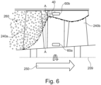
- Fig.6 shows a sectional side view of a compression section, including the aerofoil 40 previously shown in Fig.5 , which in turn forms part of a compressor within the compression system 114,115 of the gas turbine engine 100.
- the first sensor 60a is located at a first radial position 61a, measured along the spanwise direction 59 from either or both of the principal and rotational axis 209 and the base of the aerofoil 40 extending from the platform 41 towards the tip 58.
- the first sensor 60a is configured to measure the temperature of a first region of the aerofoil 40.
- the second sensor 60b is located at a second radial position 61b, measured along the spanwise direction 59 and extending from the root 57 towards the tip 58.
- the second sensor60b is configured to measure the temperature of a second region of the aerofoil 40.
- the first sensor 60a is offset from the second sensor 60b in a spanwise direction 59.
- the first region is offset from the second region in a spanwise direction 59.
- the first region is distinct from the second region.
- the first region may at least partially overlap with the second region.
- the first radial position 61a is radially offset from the second radial position 61b, relative to either or both of the principal and rotational axis 209, and the base of the aerofoil 40 extending from the platform 41 towards the tip 58.
- radial section A-A located immediately upstream of aerofoil 40. Adjacent the stator aerofoil 40 is shown an aerofoil 240a of an upstream rotor and an aerofoil 240b of a downstream rotor, relative to the direction of airflow 250, parallel to a principal and rotational axis 209. Also shown are the first sensor 60a and the second sensor 60b, which are formed within the body of the aerofoil 40. Thus, in some examples, the first sensor 60a and the second sensor 60b are shown to be positioned aft of the leading edge 45 of the aerofoil 40.
- Fig.6 also shows a cross-sectional perspective of ingested ice or liquid water 260 within a gas flow 127.
- the ingested ice or liquid water 260 flows through the compression system 114,115, it adopts a bias towards the radially outer region (outer span) of the aerofoil 40 due to the centrifugal action of the upstream and downstream rotors 240a,240b on the ingested ice or liquid water 260 present.
- the ingested ice or liquid water 260 is shown to be distributed over a substantial portion of the aerofoil 240a before being centrifuged towards the outer annulus line due to passing through and being centrifugally accelerated by the rotating stage comprising the aerofoil 240a of the upstream rotor.
- the extent to which the ingested ice or liquid water 260 is centrifuged towards the outer annulus line depends of one or more of, for example, the rotational speed of the or each rotor 240a,240b, the geometry and solidity of the or each rotor 240a,240b, the type and size of water or ice droplets or particles contained within the ingested ice or liquid water 260, and the incoming velocity of the ingested ice or liquid water 260 within the gas flow 127.
- the ingested ice or liquid water 260 is shown become concentrated towards the outer radial section of the compressor.
- the ingested ice or liquid water 260 may form a slurry, a water film, or may fully vaporise depending on operational conditions.
- Fig.7 shows a schematic of operational radial air temperature profiles along section A-A, previously shown in Fig.6 .
- Fig.7 shows a first radial air temperature profile 272 along section A-A associated with compressor operation in which no ice or liquid is being ingested.
- the temperatures detected by the temperature sensors 60a,60b will show a stable relationship with compressor gas stream temperature, so will track compressor temperatures in a predictable manner. If ice crystal ingestion or ice accretion begins to occur on the aerofoil 40, it will preferentially build up in the radially outwardly wet region of the second sensor 60b.
- Fig.7 also shows a first radial air temperature profile 270 along section A-A, caused by the sublimation, melting or evaporation of ice or liquid water towards the outer annulus line.
- first radial air temperature profile 270 As ice sublimes or melts, or water is evaporated, heat is supplied to overcome the latent heat of the phase change. This heat is provided by the surrounding air or surfaces within the gas turbine engine 100. This leads to an air temperature depression towards the outer radial section of the compressor and a subsequent change to the first radial temperature profile 270.
- the first sensor 60a is positioned at the first radial position 61a of the aerofoil 40, which is free from the temperature depression of the first radial air temperature profile 270 generated when ice or liquid water is ingested into the gas turbine engine 100.
- the second sensor 60b is positioned at the second radial position 61b of the aerofoil 40, which is reliably subjected to the temperature depression of the first radial air temperature profile 270 generated when ice or liquid water is ingested into the gas turbine engine 100.
- At least one second sensor 60b is positioned towards the outer annulus line, relative to one or more of the or each first sensor 60a, the principal and rotational axis 209 and the base of the aerofoil 40 extending from the platform 41 towards the tip 58.
- at least one second sensor 60b is situated in a second region that is reliably subjected to the temperature depression of the first radial air temperature profile 270 generated when ice or liquid water is ingested into the compressor.
- at least one first sensor 60a is positioned towards the inner annulus line, relative to one or more of the or each second sensor 60b, the principal and rotational axis 209 and the base of the aerofoil 40 extending from the platform 41 towards the tip 58.
- At least one first sensor 60a is situated in a first region that is reliably free from the temperature depression of the first radial air temperature profile 270 generated when ice or liquid water is ingested into the compressor.
- the second radial position 61b of the second sensor 60b is radially offset from the first radial position 61a of the first sensor 60a. It will be appreciated that many such configurations may exist for the specific placement of the first sensor 60a and the second sensor 60b, providing the testable conditions outlined above are met.
- Fig.8 shows a plan perspective of an aerofoil 40, and an alternate example of the arrangement shown in Fig.5 .
- the aerofoil 40 comprises a pressure surface 44 and a suction surface 43.
- the first temperature sensor 60a is provided between the pressure surface 44 and the suction surface 43.
- a first electrical heating element 72 is located adjacent the pressure surface 44.
- a second temperature sensor 60b is provided between the pressure surface 44 and the suction surface 43.
- the second electrical heating element 76 is located adjacent the suction surface 43.
- Each temperature sensor 60a,60b is heated by its adjacent electrical heater element 72,76. In the example shown, the spacing between the distinct regions helps to avoid the heating of one region directly influencing the temperature of the other.
- the sensors 60a, 60b and regions may be on equivalent surfaces, or in equivalent chordwise locations of the aerofoil 40.
- the first temperature sensor 60a and the second temperature sensor 60b may be located off-centre, i.e. off the camber line 31.
- either or both of the first temperature sensor 60a the second temperature sensor 60b may be located towards the pressure surface 44, i.e. off the camber line 31.
- either or both of the first temperature sensor 60a the second temperature sensor 60b may be located towards the suction surface 43, i.e. off the camber line 31, according to requirements.
- first temperature sensor 60a and the second temperature sensor 60b are offset in the chordwise direction. It will also be appreciated that the electrical heater elements 72,76 are offset in the chordwise direction. Thus, the second axial location 51b may be measured along the chord line 50a relative to the leading edge 45, and offset relative to the first location 51a, or vice versa. Although not shown, it will be appreciated that the first temperature sensor 60a and the second temperature sensor 60b are also offset in the spanwise direction. It will also be appreciated that the electrical heater elements 72,76 are offset in the spanwise direction. Thus, in some examples, the first and second heated regions may be both distinct, and offset in the spanwise direction such that the first temperature sensor 60a and the second temperature sensor 60b are radially offset.
- the first and second heated regions refer to the areas of the aerofoil, or aerofoil 40, heated by the respective heating elements 72,76.
- the size of the respective heated regions may be enlarged or reduced according to, for example, the size, shape, location, power requirements or input of the respective heating elements 72,76.
- the first electrical heater element 72 and the second electrical heater element 76 are also shown to be offset in the chordwise direction 59.
- the first sensor 60a is configured to measure the temperature of a first region of the aerofoil 40.
- the second sensor 60b is configured to measure the temperature of a second region of the aerofoil 40.
- the first region is distinct from the second region.
- the first region may at least partially overlap with the second region.
- the first temperature sensor 60a and the second temperature sensor 60b are axially offset.
- the two temperature sensors 60a,60b provide temperature information in the regions of interest.
- the second sensor 60b is located, during use, in the wet region.
- the first sensor 60a is situated in a radially inward region that is reliably not subjected to an intercooling effect of one or more of rain, hail or ice crystals.
- the second sensor 60b is located, during use, in the dry region.
- the controller may comprise a comparator to perform the comparison step between the temperature measured by the temperature sensors 60a,60b or a reference value, which can be stored in the memory 85, or directly between the readings of the first and second temperature sensors 60a,60b.
- the memory 85 may also record measured temperature values over time to create a measured temperature profile for comparison with a reference profile.
- Controller 81 can control various aspects of the apparatus, including one or more of heater operation, temperature measurement intervals, and data recording and comparison.
- computer readable instructions are provided to the controller 81, which may form part of a standard engine controller, for example a full authority digital engine/electronics control (FADEC), or may be provided as a stand-alone unit.
- FADEC full authority digital engine/electronics control
- the temperature measured by the second sensor 60b is appreciably lower than that by the first sensor 60a.
- the difference in measured temperature between the first sensor 60a and the second sensor 60b is compared against a threshold which may vary with compressor operating condition. If the difference in measured temperature exceeds the threshold, the ingestion of ice or liquid water ingestion may be confirmed.
- a threshold which may vary with compressor operating condition. If no ice or liquid water is being ingested, a small difference in the measured temperature between the first sensor 60a and second sensor 60b may exist due to the aerodynamic design of the compressor. If necessary, such differences may be accounted or corrected for, using knowledge of the compressor behaviour or operational characteristics.
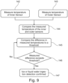
- a method of detecting ice crystal ingestion or ice accretion on an aerofoil 40, during use is illustrated in Fig.9 .
- the temperature of the first region is monitored during use at 142, and compared at step 144.
- the value calculated at step 144 is compared with a predetermined reference, temperature value, temperature profile, or threshold at step 145.
- the measured difference exceeds the predetermined reference, temperature value, temperature profile, or threshold of step 145, at step 147, ingestion of ice or liquid water may be confirmed.
- the measured difference does not exceed the predetermined reference, temperature value, temperature profile, or threshold of step 145, ingestion of ice or liquid water remains unconfirmed.
- the saturation vapour pressure of the air is low.
- the temperature depression generated by the ingestion of ice or liquid water into the compressor may be small and may be difficult to reliably detect given the measurement accuracy of the first sensor 60a and the second sensor 60b, which may be either or both of thermocouples or RTD sensors.
- either or both of the first sensor 60a and the second sensor 60b may be replaced with one or more electrically heated sensors which increase the observable temperature depression local to each respective sensor.
- one or more heated sensors may be positioned on the surface of, or may be at least partially embedded within, a compressor stator vane, within a given stage of the compression system.
- the or each sensor may be heated using an electrical power supply to maintain a constant temperature. This temperature may vary according to gas turbine engine 100 operating condition.
- the second sensor is cooled by the ingested ice or liquid water the electrical power required to keep it at its constant temperature increases.
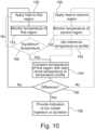
- a method of detecting ice crystal ingestion or ice accretion on a aerofoil 40, during use is illustrated in Fig.10 .
- a first step 150 heat is applied to a first region of a aerofoil 40 during use. The temperature of the first region is monitored during use at 152, and compared with a second, reference, temperature value or temperature profile at step 154.
- the heating, monitoring and comparing steps 150,152,154 are repeated until interrupted by a user, or stopped based on a predetermined time or temperature threshold. If the comparison 154 shows a difference at step 156, then an indication of ice crystal ingestion or ice accretion is provided at step 158. Ice crystal ingestion or ice accretion may be detected based simply on a comparison, at step 154, of the monitored temperatures of the first region 152 with a reference temperature close to zero degrees Celsius, for example in the range of zero to five degrees Celsius such as one or two degrees Celsius.
- heat may also be applied to second region of the aerofoil 40, during use, at step 160, and the temperature of the second region monitored during use at 162 to provide the reference temperature value or update a reference temperature profile 164 for use in the comparison step 154.
- Heat may be applied directly to the first region of the aerofoil 40 at step 150 and/or to the second region of the aerofoil 40 at step 160, for example using an electrical heating element.
- Heat may be applied 150,160 to the first and/or second region constantly during use of the aerofoil 40, or may be applied 150,160 to heat the first and/or second region to an equilibrium temperature.
- the method includes the step of checking whether an equilibrium temperature has been reached, at step 166, and the comparing step 154 is performed only once the first and/or second region has reached said equilibrium temperature.
- the rate of temperature increase of a region may be monitored as the heat is applied, by monitoring the temperature of the first region over time at step 152. This provides a measured heating profile which is compared to a reference heating/temperature profile at step 154.
- Heat may be applied only once, periodically, at irregular intervals or on demand, for example when the gas turbine engine 100 operating point changes, or based on some other trigger.
- the heat may be applied for a predetermined amount of time or until a set temperature or gas turbine engine 100 operating point is reached, or the application of heat may be entirely controlled by a user.
- Fig.11 shows a schematic view of a further example of an aerofoil 40.
- the first temperature sensor 60a and first electrical heating element 72 are provided at a first radial position 61a on the aerofoil 40.
- the second temperature sensor 60b and second electrical heater element 76 are provided at a second radial position 61b on the aerofoil 40.
- the aerofoil 40 is an electrically conductive member.
- the aerofoil 40 may be configured so that upon application of a current by the first sensor 60a or the second sensor 60b, an electrical property of the aerofoil 40 may be monitored to determine a temperature.
- the electrical property may be resistance.
- either or both of the first sensor 60a and the second sensor 60b may be configured to determine the impedance of the aerofoil 40.
- the electrical property may be impedance.
- the temperature of the aerofoil 40 at either or both of the first region and the second region may monitored or determined in this way in an equivalent manner to that described in relation to Figs.9-11 . It will also be appreciated that the arrangement may be equally applied to any further structure described herein.
- a hot wire may be used, in place of either or both of the temperature sensors 60a,60b and a heating element, with a current being passed through the wire and its resistance being measured.
- a hot wire is a sensor.
- the hot wire sensor may be made from a length of resistance wire.
- the hot wire may be, for example, circular in section. Since resistance is proportional to temperature, this would also be effective in showing the presence or absence of ice accretion. Thus, a measured temperature difference between the first and second temperature sensors 60a,60b is indicative of ice crystal ingestion or ice accretion.
- a controller 81 and memory 85 are provided in the systems of Figs.6-8 .
- a 'dry' probe such as that described in relation to figs.5-11 may be replaced with a synthesized/modelled value, such as the arrangements and methods described and claimed in EP application no.17178665.0 . and EP application no.17169041.5 .
- a synthesized/modelled value may be generated, for example, by the engine controller, from one or more of a compressor shaft speed and a gas turbine engine 100 temperature.
- the rate of change of power consumption of the wet sensor may be used to infer the occurrence of ice crystal ingestion or ice accretion.
- the first sensor 60a may be replaced by a calculated (synthesised) value within the engine control system. This synthesised value may be developed based on the engine manufacturer's knowledge of the compressor behaviour. Such an arrangement may further reduce the cost and complexity of incorporating the first sensor 60a and may offer an advantage in increasing system reliability.
- one or more of the sensors 60a,60b may be either incorporated at least partially within, or applied to any other compressor static hardware that is capable of exploiting the difference in radial temperature profile when ice or liquid water is ingested, and that may offer a more straightforward physical implementation which avoids some of the challenges above.
- Such hardware may include static structures (e.g. compressor inlet structures, inter case struts, bypass outlet guide vanes, A-frames etc.), or the inner and outer compressor casings or the stator vane platforms (tops and bottoms of the vane).
- One or more of the sensors 60a,60b may also be positioned on a purpose built body that is inserted within the main gas flow at an appropriate position in the compressor. Such an arrangement may make the system more easily line replaceable, and may simplify addition, removal, or replacement of the sensors 60a,60b.
Landscapes
- Engineering & Computer Science (AREA)
- Chemical & Material Sciences (AREA)
- Combustion & Propulsion (AREA)
- Mechanical Engineering (AREA)
- General Engineering & Computer Science (AREA)
- Aviation & Aerospace Engineering (AREA)
- Structures Of Non-Positive Displacement Pumps (AREA)
Claims (7)
- Vorrichtung zum Detektieren von einem oder beidem von Wasser- oder Eiskristallaufnahme und Eisablagerung an einer Tragfläche (40) innerhalb eines Gasturbinentriebwerks (100) mit einer Hauptdrehachse (109), wobei die Vorrichtung Folgendes umfasst:einen ersten Temperatursensor (60a) zum Bestimmen eines ersten Temperaturwertes an einer ersten radialen Position (61a) innerhalb eines ersten Bereichs der Tragfläche, relativ zu der Hauptdrehachse des Gasturbinentriebwerks;einen zweiten Temperatursensor (60b) zum Bestimmen eines zweiten Temperaturwertes an einer zweiten radialen Position (61b) innerhalb eines zweiten Bereichs der Tragfläche, relativ zu der Hauptdrehachse des Gasturbinentriebwerks; undeine Steuerung (81);wobei die zweite radiale Position des zweiten Temperatursensors radial von der ersten radialen Position des ersten Temperatursensors versetzt ist; undeiner oder beide von dem ersten Temperatursensor und dem zweiten Temperatursensor hinter einer Vorderkante (25) der Tragfläche positioniert sind;dadurch gekennzeichnet, dass die Tragfläche (40) elektrisch leitend ist, wobei die Tragfläche konfiguriert ist, sodass bei Anlegung eines Stroms der Widerstand oder die Impedanz der Tragfläche durch den ersten Temperatursensor (60a) und den zweiten Temperatursensor (60b) überwacht wird, die jeweils mit einem ersten Heizer und einem zweiten Heizer gepaart sind, wobei jeder von dem ersten Heizer und dem zweiten Heizer ein elektrisches Heizelement (72, 76) umfasst, wobei sich jeder von dem ersten Heizer und dem zweiten an oder zumindest teilweise innerhalb der Tragfläche befindet; unddie Steuerung (81) einen Komparator zum Vergleichen des ersten Temperaturwertes mit dem zweiten Temperaturwert aufweist und die Steuerung konfiguriert ist, um computerlesbare Anweisungen zu lesen, um Schritte zu Folgendem auszuführen:Bestimmen des ersten Temperaturwertes (142) an der ersten radialen Position innerhalb des ersten Bereichs der Tragfläche mit dem ersten Temperatursensor (60a);Bestimmen des zweiten Temperaturwertes (143) an der zweiten radialen Position innerhalb des zweiten Bereichs der Tragfläche mit dem zweiten Temperatursensor (60b); undVergleichen des ersten Temperaturwertes mit dem zweiten Temperaturwert (144);wobei Eiskristallaufnahme oder Eisablagerung basierend auf dem Vergleich des ersten Temperaturwertes mit dem zweiten Temperaturwert während Verwendung detektiert wird (147).
- Vorrichtung nach Anspruch 1, wobei der Widerstand der Tragfläche durch den ersten Temperatursensor (60a) und den zweiten Temperatursensor (60b) überwacht wird.
- Vorrichtung nach Anspruch 1 oder 2, wobei die Vorrichtung zwei oder mehr Sätze von jeweiligen Heizern und Temperatursensoren umfasst, wobei der zweite oder weitere Satz von jeweiligen Heizern und Temperatursensoren axial von dem ersten Satz von jeweiligen Heizern und Temperatursensoren (60a, 60b) versetzt ist.
- Vorrichtung nach einem vorhergehenden Anspruch, ferner umfassend einen Speicher (85), und wobei die Steuerung (81) konfiguriert ist, um computerlesbare Anweisungen zu lesen, um Schritte zu Folgendem auszuführen:Überwachen (152, 162) der Rate der Temperaturerhöhung des ersten Bereichs und des zweiten Bereichs, während die Wärme angelegt wird, um ein jeweiliges gemessenes Heizprofil bereitzustellen;Speichern der gemessenen Heizprofile in dem Speicher; undVergleichen (154) der gemessenen Heizprofile in dem Vergleichsschritt mit Referenztemperaturprofilen.
- Leitschaufel zur Verwendung in einem Gasturbinentriebwerk (100), wobei die Leitschaufel die Vorrichtung nach einem der Ansprüche 1 bis 4 umfasst.
- Strebe zur Verwendung in einem Gasturbinentriebwerk (100), wobei die Strebe die Vorrichtung nach einem der Ansprüche 1 bis 4 umfasst.
- Gasturbinentriebwerk (100), das eine Leitschaufel nach Anspruch 5 oder eine Strebe nach Anspruch 6 umfasst.
Applications Claiming Priority (1)
| Application Number | Priority Date | Filing Date | Title |
|---|---|---|---|
| GBGB1820301.8A GB201820301D0 (en) | 2018-12-13 | 2018-12-13 | Water and ice detection |
Publications (2)
| Publication Number | Publication Date |
|---|---|
| EP3667032A1 EP3667032A1 (de) | 2020-06-17 |
| EP3667032B1 true EP3667032B1 (de) | 2025-01-01 |
Family
ID=65147229
Family Applications (1)
| Application Number | Title | Priority Date | Filing Date |
|---|---|---|---|
| EP19208761.7A Active EP3667032B1 (de) | 2018-12-13 | 2019-11-13 | Wasser- und eisdetektion für ein gasturbinenprofil |
Country Status (3)
| Country | Link |
|---|---|
| US (1) | US11884405B2 (de) |
| EP (1) | EP3667032B1 (de) |
| GB (1) | GB201820301D0 (de) |
Families Citing this family (9)
| Publication number | Priority date | Publication date | Assignee | Title |
|---|---|---|---|---|
| US11879345B2 (en) | 2020-02-28 | 2024-01-23 | Rosemount Aerospace Inc. | Pressure and temperature sensors and methods of removing ice from pressure and temperature sensors |
| US11773745B2 (en) | 2020-02-28 | 2023-10-03 | Rosemount Aerospace Inc. | Pressure and temperature sensors and methods of controlling ice accretion on pressure and temperature sensors |
| US11655726B2 (en) * | 2020-02-28 | 2023-05-23 | Rosemount Aerospace Inc. | Pressure and temperature sensors and related methods |
| GB202115579D0 (en) * | 2021-10-29 | 2021-12-15 | Rolls Royce Plc | Protection system for gas turbine engine in ice crystal conditions |
| US12509993B1 (en) * | 2022-01-21 | 2025-12-30 | Rtx Corporation | Composite airfoil with integrated anti-icing for an aircraft propulsion system |
| US12296964B2 (en) * | 2022-10-19 | 2025-05-13 | Goodrich Corporation | Ice protection backup temperature control logic |
| US12188410B2 (en) | 2023-01-24 | 2025-01-07 | Pratt & Whitney Canada Corp. | Icing condition identification for gas turbine engine |
| FR3154980A1 (fr) * | 2023-11-08 | 2025-05-09 | Safran Aircraft Engines | Procédé de surveillance de turbomachine |
| CN118462337B (zh) * | 2024-07-09 | 2024-11-15 | 华能平凉发电有限责任公司 | 一种汽轮机汽缸监控装置 |
Family Cites Families (34)
| Publication number | Priority date | Publication date | Assignee | Title |
|---|---|---|---|---|
| GB2023291B (en) | 1978-06-15 | 1982-12-15 | Vykhodstev N A | Detecting icing conditions |
| US4210021A (en) * | 1978-07-06 | 1980-07-01 | Bantsekin Viktor I | Method and device for detecting icing of objects found in air flow |
| US4333004A (en) | 1980-02-19 | 1982-06-01 | Dataproducts New England, Inc. | Detecting ice forming weather conditions |
| US4379227A (en) * | 1980-04-21 | 1983-04-05 | Paul Kovacs | Apparatus for and a method of monitoring the build-up of ice |
| US5206806A (en) * | 1989-01-10 | 1993-04-27 | Gerardi Joseph J | Smart skin ice detection and de-icing system |
| FR2681377B1 (fr) | 1991-09-18 | 1995-01-20 | Snecma | Systeme de protection contre l'extinction d'une turbomachine en cas d'ingestion d'eau massive ou de greles. |
| GB9305414D0 (en) | 1993-03-16 | 1993-05-05 | Rolls Royce Plc | Gas turbine engine water ingestion |
| US5934617A (en) * | 1997-09-22 | 1999-08-10 | Northcoast Technologies | De-ice and anti-ice system and method for aircraft surfaces |
| NO307723B1 (no) * | 1997-11-05 | 2000-05-15 | Futuris As | Fremgangsmåte og anordning for deteksjon |
| US6644009B2 (en) | 2001-12-20 | 2003-11-11 | General Electric Co. | Methods and apparatus for operating gas turbine engines |
| US7014357B2 (en) | 2002-11-19 | 2006-03-21 | Rosemount Aerospace Inc. | Thermal icing conditions detector |
| US7175136B2 (en) * | 2003-04-16 | 2007-02-13 | The Boeing Company | Method and apparatus for detecting conditions conducive to ice formation |
| US7191643B2 (en) | 2004-06-03 | 2007-03-20 | University Corporation For Atmospheric Research | Sensor system to distinguish frozen and non-frozen liquid particulates |
| EP2117926B1 (de) | 2007-01-10 | 2018-12-26 | Sikorsky Aircraft Corporation | Eisgeschwindigkeitsmesser mit virtueller aspiration |
| GB2447238B (en) | 2007-03-07 | 2009-11-18 | Rolls Royce Plc | Method for detecting ice ingestion in a gas turbine engine |
| US8006934B2 (en) * | 2008-03-31 | 2011-08-30 | United Technologies Corporation | Heating architecture for a composite fairing |
| CA2786838C (en) * | 2010-01-14 | 2017-01-10 | Saab Ab | Multifunctional de-icing/anti-icing system |
| FR2964144B1 (fr) | 2010-08-30 | 2012-09-28 | Snecma | Detection d'une ingestion d'eau ou de grele dans une turbomachine |
| US8515711B2 (en) | 2010-10-21 | 2013-08-20 | Siemens Energy, Inc. | Diagnostic system and method for monitoring operating conditions of components of a turbine machine |
| EP3575218B1 (de) * | 2010-12-31 | 2021-08-11 | Battelle Memorial Institute | Antenne mit schicht aus kohlenstoff-nanoröhrchen |
| US9133773B2 (en) * | 2011-07-08 | 2015-09-15 | United Technologies Corporation | Method and controller for detecting ice |
| US9201031B2 (en) | 2012-07-06 | 2015-12-01 | Science Engineering Associates, Inc. | Cloud ice detector |
| US9346550B2 (en) * | 2012-12-05 | 2016-05-24 | Mesoscribe Technologies, Inc. | Ice detection and mitigation device |
| GB2509729B (en) * | 2013-01-11 | 2014-12-17 | Ultra Electronics Ltd | Apparatus and method for detecting water or ice |
| GB2511343B (en) * | 2013-02-28 | 2015-07-22 | Gkn Aerospace Services Ltd | Ice protection system |
| EP2781698A1 (de) * | 2013-03-20 | 2014-09-24 | Siemens Aktiengesellschaft | Gasturbine und Verfahren zum Betreiben der Gasturbine |
| EP2826993B1 (de) * | 2013-07-17 | 2017-04-12 | ADIOS Patent GmbH | Windenergieanlagenrotorblattenteisungsverfahren sowie Windenergieanlagenrotorblattenteisungssystem |
| US9624787B2 (en) * | 2013-09-30 | 2017-04-18 | Rosemount Aerospace Inc. | Total air temperature sensors |
| US9745070B2 (en) * | 2014-11-11 | 2017-08-29 | The Boeing Company | Systems for multiple zone heaters for rotor craft and methods of operation |
| US9970824B2 (en) * | 2015-06-29 | 2018-05-15 | Pratt & Whitney Canada Corp. | Sensor probe with anti-icing |
| WO2017108064A1 (en) * | 2015-12-23 | 2017-06-29 | Vestas Wind Systems A/S | Improved electro-thermal heating |
| US20180298778A1 (en) * | 2017-04-18 | 2018-10-18 | Honeywell International Inc. | Gas turbine engine particulate ingestion and accumulation sensor system and method |
| BE1025263B1 (fr) * | 2017-05-31 | 2019-01-07 | Safran Aero Boosters S.A. | Compresseur degivrant de turbomachine et procede de degivrage |
| GB201711689D0 (en) * | 2017-07-20 | 2017-09-06 | Rolls Royce Plc | Ice detection |
-
2018
- 2018-12-13 GB GBGB1820301.8A patent/GB201820301D0/en not_active Ceased
-
2019
- 2019-11-13 EP EP19208761.7A patent/EP3667032B1/de active Active
- 2019-11-14 US US16/683,819 patent/US11884405B2/en active Active
Also Published As
| Publication number | Publication date |
|---|---|
| EP3667032A1 (de) | 2020-06-17 |
| US20200189754A1 (en) | 2020-06-18 |
| GB201820301D0 (en) | 2019-01-30 |
| US11884405B2 (en) | 2024-01-30 |
Similar Documents
| Publication | Publication Date | Title |
|---|---|---|
| EP3667032B1 (de) | Wasser- und eisdetektion für ein gasturbinenprofil | |
| US11346239B2 (en) | Heat flux measurement system | |
| EP3431720B1 (de) | Eisdetektion für gasturbinenkomponente | |
| US20170298760A1 (en) | Axial Turbine Engine Compressor De-Icing Blade | |
| BR102016005843A2 (pt) | método para determinar um fator saúde de motor e dispositivo de computação | |
| WO2009086358A1 (en) | Fan stall detection system | |
| US11313245B2 (en) | Shaft monitoring system | |
| US20100290906A1 (en) | Plasma sensor stall control system and turbomachinery diagnostics | |
| US10794294B1 (en) | Efficient jet | |
| EP3620797B1 (de) | System und computerlesbares speichermedium für aerodynamische sonden mit variabler ausrichtung | |
| EP3418703B1 (de) | Lufttemperatursensor | |
| EP3686561B1 (de) | Wellenüberwachungssystem | |
| EP3269944B1 (de) | Verfahren zum betrieb eines gasturbinenmotors | |
| GB2577963A (en) | Air temperature sensor having a bushing | |
| EP3260657A1 (de) | Minischeibe für einen gasturbinenmotor | |
| CN109115370B (zh) | 气温传感器和减少误差的方法 | |
| CA3237809A1 (en) | System and method for identifying blockage of an air intake for an aircraft propulsion system | |
| EP3447253B1 (de) | Überwachung der dehnbeanspruchung der fan-schaufeln eines turbofanstrahltriebwerks | |
| EP4174288B1 (de) | Schutzsystem für gasturbinenmotor unter eiskristallbedingungen | |
| CN117189363A (zh) | 具有容纳非管道式涡轮发动机的机身的飞行器 | |
| US20200240422A1 (en) | Shaft monitoring system | |
| US12385808B2 (en) | Accretion detection systems and associated methods for gas turbine engines | |
| EP4407168B1 (de) | Erkennung des vereisungszustands für gasturbinenmotor | |
| US20260117784A1 (en) | Low pitch protection control system | |
| US20100205928A1 (en) | Rotor stall sensor system |
Legal Events
| Date | Code | Title | Description |
|---|---|---|---|
| PUAI | Public reference made under article 153(3) epc to a published international application that has entered the european phase |
Free format text: ORIGINAL CODE: 0009012 |
|
| STAA | Information on the status of an ep patent application or granted ep patent |
Free format text: STATUS: THE APPLICATION HAS BEEN PUBLISHED |
|
| AK | Designated contracting states |
Kind code of ref document: A1 Designated state(s): AL AT BE BG CH CY CZ DE DK EE ES FI FR GB GR HR HU IE IS IT LI LT LU LV MC MK MT NL NO PL PT RO RS SE SI SK SM TR |
|
| AX | Request for extension of the european patent |
Extension state: BA ME |
|
| STAA | Information on the status of an ep patent application or granted ep patent |
Free format text: STATUS: REQUEST FOR EXAMINATION WAS MADE |
|
| 17P | Request for examination filed |
Effective date: 20201216 |
|
| RBV | Designated contracting states (corrected) |
Designated state(s): AL AT BE BG CH CY CZ DE DK EE ES FI FR GB GR HR HU IE IS IT LI LT LU LV MC MK MT NL NO PL PT RO RS SE SI SK SM TR |
|
| STAA | Information on the status of an ep patent application or granted ep patent |
Free format text: STATUS: EXAMINATION IS IN PROGRESS |
|
| 17Q | First examination report despatched |
Effective date: 20220204 |
|
| REG | Reference to a national code |
Ref country code: DE Ref legal event code: R079 Free format text: PREVIOUS MAIN CLASS: F01D0025020000 Ipc: B64D0015120000 Ref country code: DE Ref legal event code: R079 Ref document number: 602019064188 Country of ref document: DE Free format text: PREVIOUS MAIN CLASS: F01D0025020000 Ipc: B64D0015120000 |
|
| RIC1 | Information provided on ipc code assigned before grant |
Ipc: B64D 15/22 20060101ALI20230116BHEP Ipc: F01D 21/00 20060101ALI20230116BHEP Ipc: F01D 17/08 20060101ALI20230116BHEP Ipc: F02C 7/047 20060101ALI20230116BHEP Ipc: F01D 25/02 20060101ALI20230116BHEP Ipc: B64D 15/12 20060101AFI20230116BHEP |
|
| GRAP | Despatch of communication of intention to grant a patent |
Free format text: ORIGINAL CODE: EPIDOSNIGR1 |
|
| STAA | Information on the status of an ep patent application or granted ep patent |
Free format text: STATUS: GRANT OF PATENT IS INTENDED |
|
| GRAS | Grant fee paid |
Free format text: ORIGINAL CODE: EPIDOSNIGR3 |
|
| INTG | Intention to grant announced |
Effective date: 20241023 |
|
| GRAA | (expected) grant |
Free format text: ORIGINAL CODE: 0009210 |
|
| STAA | Information on the status of an ep patent application or granted ep patent |
Free format text: STATUS: THE PATENT HAS BEEN GRANTED |
|
| P01 | Opt-out of the competence of the unified patent court (upc) registered |
Free format text: CASE NUMBER: APP_59468/2024 Effective date: 20241031 |
|
| AK | Designated contracting states |
Kind code of ref document: B1 Designated state(s): AL AT BE BG CH CY CZ DE DK EE ES FI FR GB GR HR HU IE IS IT LI LT LU LV MC MK MT NL NO PL PT RO RS SE SI SK SM TR |
|
| REG | Reference to a national code |
Ref country code: GB Ref legal event code: FG4D |
|
| REG | Reference to a national code |
Ref country code: DE Ref legal event code: R096 Ref document number: 602019064188 Country of ref document: DE |
|
| REG | Reference to a national code |
Ref country code: CH Ref legal event code: EP |
|
| REG | Reference to a national code |
Ref country code: IE Ref legal event code: FG4D |
|
| REG | Reference to a national code |
Ref country code: LT Ref legal event code: MG9D |
|
| REG | Reference to a national code |
Ref country code: NL Ref legal event code: MP Effective date: 20250101 |
|
| REG | Reference to a national code |
Ref country code: AT Ref legal event code: MK05 Ref document number: 1756013 Country of ref document: AT Kind code of ref document: T Effective date: 20250101 |
|
| PG25 | Lapsed in a contracting state [announced via postgrant information from national office to epo] |
Ref country code: NL Free format text: LAPSE BECAUSE OF FAILURE TO SUBMIT A TRANSLATION OF THE DESCRIPTION OR TO PAY THE FEE WITHIN THE PRESCRIBED TIME-LIMIT Effective date: 20250101 |
|
| PG25 | Lapsed in a contracting state [announced via postgrant information from national office to epo] |
Ref country code: FI Free format text: LAPSE BECAUSE OF FAILURE TO SUBMIT A TRANSLATION OF THE DESCRIPTION OR TO PAY THE FEE WITHIN THE PRESCRIBED TIME-LIMIT Effective date: 20250101 |
|
| PG25 | Lapsed in a contracting state [announced via postgrant information from national office to epo] |
Ref country code: PL Free format text: LAPSE BECAUSE OF FAILURE TO SUBMIT A TRANSLATION OF THE DESCRIPTION OR TO PAY THE FEE WITHIN THE PRESCRIBED TIME-LIMIT Effective date: 20250101 |
|
| PG25 | Lapsed in a contracting state [announced via postgrant information from national office to epo] |
Ref country code: ES Free format text: LAPSE BECAUSE OF FAILURE TO SUBMIT A TRANSLATION OF THE DESCRIPTION OR TO PAY THE FEE WITHIN THE PRESCRIBED TIME-LIMIT Effective date: 20250101 |
|
| PG25 | Lapsed in a contracting state [announced via postgrant information from national office to epo] |
Ref country code: IS Free format text: LAPSE BECAUSE OF FAILURE TO SUBMIT A TRANSLATION OF THE DESCRIPTION OR TO PAY THE FEE WITHIN THE PRESCRIBED TIME-LIMIT Effective date: 20250501 Ref country code: NO Free format text: LAPSE BECAUSE OF FAILURE TO SUBMIT A TRANSLATION OF THE DESCRIPTION OR TO PAY THE FEE WITHIN THE PRESCRIBED TIME-LIMIT Effective date: 20250401 |
|
| PG25 | Lapsed in a contracting state [announced via postgrant information from national office to epo] |
Ref country code: HR Free format text: LAPSE BECAUSE OF FAILURE TO SUBMIT A TRANSLATION OF THE DESCRIPTION OR TO PAY THE FEE WITHIN THE PRESCRIBED TIME-LIMIT Effective date: 20250101 |
|
| PG25 | Lapsed in a contracting state [announced via postgrant information from national office to epo] |
Ref country code: PT Free format text: LAPSE BECAUSE OF FAILURE TO SUBMIT A TRANSLATION OF THE DESCRIPTION OR TO PAY THE FEE WITHIN THE PRESCRIBED TIME-LIMIT Effective date: 20250502 Ref country code: LV Free format text: LAPSE BECAUSE OF FAILURE TO SUBMIT A TRANSLATION OF THE DESCRIPTION OR TO PAY THE FEE WITHIN THE PRESCRIBED TIME-LIMIT Effective date: 20250101 |
|
| PG25 | Lapsed in a contracting state [announced via postgrant information from national office to epo] |
Ref country code: GR Free format text: LAPSE BECAUSE OF FAILURE TO SUBMIT A TRANSLATION OF THE DESCRIPTION OR TO PAY THE FEE WITHIN THE PRESCRIBED TIME-LIMIT Effective date: 20250402 Ref country code: BG Free format text: LAPSE BECAUSE OF FAILURE TO SUBMIT A TRANSLATION OF THE DESCRIPTION OR TO PAY THE FEE WITHIN THE PRESCRIBED TIME-LIMIT Effective date: 20250101 |
|
| PG25 | Lapsed in a contracting state [announced via postgrant information from national office to epo] |
Ref country code: AT Free format text: LAPSE BECAUSE OF FAILURE TO SUBMIT A TRANSLATION OF THE DESCRIPTION OR TO PAY THE FEE WITHIN THE PRESCRIBED TIME-LIMIT Effective date: 20250101 |
|
| PG25 | Lapsed in a contracting state [announced via postgrant information from national office to epo] |
Ref country code: CZ Free format text: LAPSE BECAUSE OF FAILURE TO SUBMIT A TRANSLATION OF THE DESCRIPTION OR TO PAY THE FEE WITHIN THE PRESCRIBED TIME-LIMIT Effective date: 20250101 |
|
| PG25 | Lapsed in a contracting state [announced via postgrant information from national office to epo] |
Ref country code: SE Free format text: LAPSE BECAUSE OF FAILURE TO SUBMIT A TRANSLATION OF THE DESCRIPTION OR TO PAY THE FEE WITHIN THE PRESCRIBED TIME-LIMIT Effective date: 20250101 |
|
| REG | Reference to a national code |
Ref country code: DE Ref legal event code: R097 Ref document number: 602019064188 Country of ref document: DE |
|
| PG25 | Lapsed in a contracting state [announced via postgrant information from national office to epo] |
Ref country code: SM Free format text: LAPSE BECAUSE OF FAILURE TO SUBMIT A TRANSLATION OF THE DESCRIPTION OR TO PAY THE FEE WITHIN THE PRESCRIBED TIME-LIMIT Effective date: 20250101 |
|
| PG25 | Lapsed in a contracting state [announced via postgrant information from national office to epo] |
Ref country code: DK Free format text: LAPSE BECAUSE OF FAILURE TO SUBMIT A TRANSLATION OF THE DESCRIPTION OR TO PAY THE FEE WITHIN THE PRESCRIBED TIME-LIMIT Effective date: 20250101 |
|
| PG25 | Lapsed in a contracting state [announced via postgrant information from national office to epo] |
Ref country code: IT Free format text: LAPSE BECAUSE OF FAILURE TO SUBMIT A TRANSLATION OF THE DESCRIPTION OR TO PAY THE FEE WITHIN THE PRESCRIBED TIME-LIMIT Effective date: 20250101 |
|
| PG25 | Lapsed in a contracting state [announced via postgrant information from national office to epo] |
Ref country code: EE Free format text: LAPSE BECAUSE OF FAILURE TO SUBMIT A TRANSLATION OF THE DESCRIPTION OR TO PAY THE FEE WITHIN THE PRESCRIBED TIME-LIMIT Effective date: 20250101 |
|
| PG25 | Lapsed in a contracting state [announced via postgrant information from national office to epo] |
Ref country code: RO Free format text: LAPSE BECAUSE OF FAILURE TO SUBMIT A TRANSLATION OF THE DESCRIPTION OR TO PAY THE FEE WITHIN THE PRESCRIBED TIME-LIMIT Effective date: 20250101 |
|
| PG25 | Lapsed in a contracting state [announced via postgrant information from national office to epo] |
Ref country code: SK Free format text: LAPSE BECAUSE OF FAILURE TO SUBMIT A TRANSLATION OF THE DESCRIPTION OR TO PAY THE FEE WITHIN THE PRESCRIBED TIME-LIMIT Effective date: 20250101 |
|
| PLBE | No opposition filed within time limit |
Free format text: ORIGINAL CODE: 0009261 |
|
| STAA | Information on the status of an ep patent application or granted ep patent |
Free format text: STATUS: NO OPPOSITION FILED WITHIN TIME LIMIT |
|
| 26N | No opposition filed |
Effective date: 20251002 |
|
| PGFP | Annual fee paid to national office [announced via postgrant information from national office to epo] |
Ref country code: DE Payment date: 20251126 Year of fee payment: 7 |
|
| PGFP | Annual fee paid to national office [announced via postgrant information from national office to epo] |
Ref country code: GB Payment date: 20251125 Year of fee payment: 7 |
|
| PGFP | Annual fee paid to national office [announced via postgrant information from national office to epo] |
Ref country code: FR Payment date: 20251124 Year of fee payment: 7 |