EP3667028B1 - Blockierungsverhinderer für kühlluftzufuhrloch mit formvertiefter oberfläche für ein gasturbinentriebwerk - Google Patents
Blockierungsverhinderer für kühlluftzufuhrloch mit formvertiefter oberfläche für ein gasturbinentriebwerk Download PDFInfo
- Publication number
- EP3667028B1 EP3667028B1 EP19215954.9A EP19215954A EP3667028B1 EP 3667028 B1 EP3667028 B1 EP 3667028B1 EP 19215954 A EP19215954 A EP 19215954A EP 3667028 B1 EP3667028 B1 EP 3667028B1
- Authority
- EP
- European Patent Office
- Prior art keywords
- passages
- vane
- passage
- metering
- vane ring
- Prior art date
- Legal status (The legal status is an assumption and is not a legal conclusion. Google has not performed a legal analysis and makes no representation as to the accuracy of the status listed.)
- Active
Links
Images





Classifications
-
- F—MECHANICAL ENGINEERING; LIGHTING; HEATING; WEAPONS; BLASTING
- F01—MACHINES OR ENGINES IN GENERAL; ENGINE PLANTS IN GENERAL; STEAM ENGINES
- F01D—NON-POSITIVE DISPLACEMENT MACHINES OR ENGINES, e.g. STEAM TURBINES
- F01D5/00—Blades; Blade-carrying members; Heating, heat-insulating, cooling or antivibration means on the blades or the members
- F01D5/12—Blades
- F01D5/14—Form or construction
- F01D5/18—Hollow blades, i.e. blades with cooling or heating channels or cavities; Heating, heat-insulating or cooling means on blades
- F01D5/187—Convection cooling
-
- F—MECHANICAL ENGINEERING; LIGHTING; HEATING; WEAPONS; BLASTING
- F01—MACHINES OR ENGINES IN GENERAL; ENGINE PLANTS IN GENERAL; STEAM ENGINES
- F01D—NON-POSITIVE DISPLACEMENT MACHINES OR ENGINES, e.g. STEAM TURBINES
- F01D9/00—Stators
- F01D9/02—Nozzles; Nozzle boxes; Stator blades; Guide conduits, e.g. individual nozzles
- F01D9/04—Nozzles; Nozzle boxes; Stator blades; Guide conduits, e.g. individual nozzles forming ring or sector
- F01D9/041—Nozzles; Nozzle boxes; Stator blades; Guide conduits, e.g. individual nozzles forming ring or sector using blades
-
- F—MECHANICAL ENGINEERING; LIGHTING; HEATING; WEAPONS; BLASTING
- F01—MACHINES OR ENGINES IN GENERAL; ENGINE PLANTS IN GENERAL; STEAM ENGINES
- F01D—NON-POSITIVE DISPLACEMENT MACHINES OR ENGINES, e.g. STEAM TURBINES
- F01D9/00—Stators
- F01D9/02—Nozzles; Nozzle boxes; Stator blades; Guide conduits, e.g. individual nozzles
- F01D9/04—Nozzles; Nozzle boxes; Stator blades; Guide conduits, e.g. individual nozzles forming ring or sector
- F01D9/042—Nozzles; Nozzle boxes; Stator blades; Guide conduits, e.g. individual nozzles forming ring or sector fixing blades to stators
-
- F—MECHANICAL ENGINEERING; LIGHTING; HEATING; WEAPONS; BLASTING
- F01—MACHINES OR ENGINES IN GENERAL; ENGINE PLANTS IN GENERAL; STEAM ENGINES
- F01D—NON-POSITIVE DISPLACEMENT MACHINES OR ENGINES, e.g. STEAM TURBINES
- F01D25/00—Component parts, details, or accessories, not provided for in, or of interest apart from, other groups
- F01D25/08—Cooling; Heating; Heat-insulation
- F01D25/12—Cooling
-
- F—MECHANICAL ENGINEERING; LIGHTING; HEATING; WEAPONS; BLASTING
- F01—MACHINES OR ENGINES IN GENERAL; ENGINE PLANTS IN GENERAL; STEAM ENGINES
- F01D—NON-POSITIVE DISPLACEMENT MACHINES OR ENGINES, e.g. STEAM TURBINES
- F01D25/00—Component parts, details, or accessories, not provided for in, or of interest apart from, other groups
- F01D25/08—Cooling; Heating; Heat-insulation
- F01D25/14—Casings modified therefor
-
- F—MECHANICAL ENGINEERING; LIGHTING; HEATING; WEAPONS; BLASTING
- F01—MACHINES OR ENGINES IN GENERAL; ENGINE PLANTS IN GENERAL; STEAM ENGINES
- F01D—NON-POSITIVE DISPLACEMENT MACHINES OR ENGINES, e.g. STEAM TURBINES
- F01D25/00—Component parts, details, or accessories, not provided for in, or of interest apart from, other groups
- F01D25/24—Casings; Casing parts, e.g. diaphragms, casing fastenings
- F01D25/246—Fastening of diaphragms or stator-rings
-
- F—MECHANICAL ENGINEERING; LIGHTING; HEATING; WEAPONS; BLASTING
- F05—INDEXING SCHEMES RELATING TO ENGINES OR PUMPS IN VARIOUS SUBCLASSES OF CLASSES F01-F04
- F05D—INDEXING SCHEME FOR ASPECTS RELATING TO NON-POSITIVE-DISPLACEMENT MACHINES OR ENGINES, GAS-TURBINES OR JET-PROPULSION PLANTS
- F05D2240/00—Components
- F05D2240/10—Stators
- F05D2240/11—Shroud seal segments
-
- F—MECHANICAL ENGINEERING; LIGHTING; HEATING; WEAPONS; BLASTING
- F05—INDEXING SCHEMES RELATING TO ENGINES OR PUMPS IN VARIOUS SUBCLASSES OF CLASSES F01-F04
- F05D—INDEXING SCHEME FOR ASPECTS RELATING TO NON-POSITIVE-DISPLACEMENT MACHINES OR ENGINES, GAS-TURBINES OR JET-PROPULSION PLANTS
- F05D2240/00—Components
- F05D2240/10—Stators
- F05D2240/12—Fluid guiding means, e.g. vanes
-
- F—MECHANICAL ENGINEERING; LIGHTING; HEATING; WEAPONS; BLASTING
- F05—INDEXING SCHEMES RELATING TO ENGINES OR PUMPS IN VARIOUS SUBCLASSES OF CLASSES F01-F04
- F05D—INDEXING SCHEME FOR ASPECTS RELATING TO NON-POSITIVE-DISPLACEMENT MACHINES OR ENGINES, GAS-TURBINES OR JET-PROPULSION PLANTS
- F05D2240/00—Components
- F05D2240/80—Platforms for stationary or moving blades
- F05D2240/81—Cooled platforms
-
- F—MECHANICAL ENGINEERING; LIGHTING; HEATING; WEAPONS; BLASTING
- F05—INDEXING SCHEMES RELATING TO ENGINES OR PUMPS IN VARIOUS SUBCLASSES OF CLASSES F01-F04
- F05D—INDEXING SCHEME FOR ASPECTS RELATING TO NON-POSITIVE-DISPLACEMENT MACHINES OR ENGINES, GAS-TURBINES OR JET-PROPULSION PLANTS
- F05D2260/00—Function
- F05D2260/20—Heat transfer, e.g. cooling
- F05D2260/201—Heat transfer, e.g. cooling by impingement of a fluid
-
- F—MECHANICAL ENGINEERING; LIGHTING; HEATING; WEAPONS; BLASTING
- F05—INDEXING SCHEMES RELATING TO ENGINES OR PUMPS IN VARIOUS SUBCLASSES OF CLASSES F01-F04
- F05D—INDEXING SCHEME FOR ASPECTS RELATING TO NON-POSITIVE-DISPLACEMENT MACHINES OR ENGINES, GAS-TURBINES OR JET-PROPULSION PLANTS
- F05D2260/00—Function
- F05D2260/60—Fluid transfer
- F05D2260/607—Preventing clogging or obstruction of flow paths by dirt, dust, or foreign particles
Definitions
- the present disclosure relates to a gas turbine engine and, more particularly, to the protection of turbine vanes from particulate blockage of airfoil cooling circuits.
- Gas turbine engines typically include a compressor section to pressurize airflow, a combustor section to burn a hydrocarbon fuel in the presence of the pressurized air, and a turbine section to extract energy from the resultant combustion gases.
- the combustion gases commonly exceed 2000 degrees F (1093 degrees C).
- Cooling of engine components such as the high pressure turbine vane may be complicated by the presence of entrained particulates in the secondary cooling air that are carried through the engine.
- a single point feed passage to each airfoil cooling circuit may be prone to blockage by foreign object particles. If these single source feed apertures become blocked, the associated downstream airfoil cooling circuit is starved of cooling air which may result in airfoil distress.
- US 2018/230836 A1 discloses a prior art vane ring, wherein the vanes are internally cooled and the internal cooling circuit receives cooling air through a feed passage connected to a metering passage. Secondary passages feeding the metering passage are formed on an impingement plate.
- US 2013/266416 A1 discloses a prior art cooling system for a turbine engine.
- US 2017/002671 A1 discloses a prior art axial transfer tube.
- US 2007/048122 A1 discloses a prior art debris-filtering technique for a gas turbine engine component air cooling system.
- a vane ring for a gas turbine engine component as recited in claim 1.
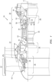
- FIG. 1 schematically illustrates a gas turbine engine 20.
- the gas turbine engine 20 is disclosed herein as a two-spool turbo fan that generally incorporates a fan section 22, a compressor section 24, a combustor section 26 and a turbine section 28.
- the fan section 22 drives air along a bypass flowpath while the compressor section 24 drives air along a core flowpath for compression and communication into the combustor section 26 then expansion through the turbine section 28.
- the concepts described herein may be applied to other turbine engine architectures such as turbojets, turboshafts, and three-spool (plus fan) turbofans.
- the engine 20 generally includes a low spool 30 and a high spool 32 mounted for rotation about an engine central longitudinal axis A relative to an engine case structure 36 via several bearing structures 38.
- the low spool 30 generally includes an inner shaft 40 that interconnects a fan 42, a low pressure compressor (“LPC”) 44 and a low pressure turbine (“LPT”) 46.
- the inner shaft 40 drives the fan 42 directly or through a geared architecture 48 to drive the fan 42 at a lower speed than the low spool 30.
- An exemplary reduction transmission is an epicyclic transmission, namely a planetary or star gear system.
- the high spool 32 includes an outer shaft 50 that interconnects a high pressure compressor (“HPC”) 52 and high pressure turbine (“HPT”) 54.
- a combustor 56 is arranged between the high pressure compressor 52 and the high pressure turbine 54.
- the inner shaft 40 and the outer shaft 50 are concentric and rotate about the engine central longitudinal axis A which is collinear with their longitudinal axes.
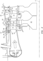
- a full ring shroud assembly 60 within the engine case structure 36 supports a blade outer air seal (BOAS) assembly 62.
- the blade outer air seal (BOAS) assembly 62 contains a multiple of circumferentially distributed BOAS proximate to a rotor assembly 66.
- the full ring shroud assembly 60 and the blade outer air seal (BOAS) assembly 62 are axially disposed between a forward stationary vane ring 68 and an aft stationary vane ring 70.
- Each vane ring 68, 70 includes an array of vanes 72, 74 that extend between a respective inner vane platform 76, 78 and an outer vane platform 80, 82.
- the inner vane platforms 76, 78 and the outer vane platforms 80, 82 attach their respective vane ring 68, 70 to the engine case structure 36.
- the blade outer air seal (BOAS) assembly 62 is affixed to the engine case structure 36 to form an annular chamber between the blade outer air seal (BOAS) assembly 62 and the engine case structure 36.
- the blade outer air seal (BOAS) assembly 62 bounds the working medium combustion gas flow in a primary flow path 94.
- the vane rings 68, 70 align the flow of the working medium combustion gas flow while the rotor blades 90 collect the energy of the working medium combustion gas flow to drive the turbine section 28 which in turn drives the compressor section 24.
- the aft stationary vane ring 70 is mounted to the engine case structure 36 downstream of the blade outer air seal (BOAS) assembly 62 by a vane support 98.
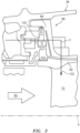
- the vane support 98 extends from the outer vane platform 82 and may include an annular hooked rail 84 (also shown in FIG. 3 ) that engages the engine case structure 36.
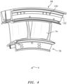
- the annular hooked rail 84 includes a feed passage 100 (also shown in FIG. 3 and FIG. 4 ) for each vane 74.
- the feed passage 100 supplies the cooling air "C" to an airfoil cooling circuit 102 distributed within the respective vane 74. That is, each vane 74 receives cooling air "C” from one respective feed passage 100 ( FIG. 4 ) that feeds the airfoil cooling circuit 102.
- the feed passage is about 0.1 inches (2.5 mm) in diameter.
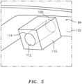
- one example of the feed passage 100 includes an extension 110 with a metering passage 112 in communication with the feed passage 100.
- the extension 110 projects from a surface 122 of the annular hooked rail 84.
- the surface 122 is an annular face transverse to the engine axis A.
- the extension 110 is generally cubic in shape, however, other shapes such as cylinders, polygons, and others may be utilized.
- the extension 110 may be a standalone feature or, alternatively, an anti-rotation feature for the stationary vane ring 70.
- the extension 110 may be a cast integral with the outer vane platform 80 or may be separately machined and attached thereto in communication with the feed passage 100.
- Cooling airflow "C" communicated to the plenum 120 ( FIG. 3 ) generally scrubs along the surface 122 such that foreign object particles therein have a lessened tendency to enter an entrance 114 to the metering passage 112 as the entrance 114 is displaced from the surface 122.
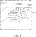
- another example of the feed passage 100 includes an extension 130 with a metering passage 132 and a multiple of secondary passages 134, 136, 138, 140 in each face 142, 144, 146, 148 of the extension 130 transverse to the metering passage 132.
- the metering passage 132 is sized to meter the flow into the airfoil cooling circuit 102 within the vane 74 such that the secondary passages 134, 136, 138, 140 need not be specifically sized to meter the cooling flow "C".
- Cooling airflow within the plenum 120 adjacent the outer vane platform 80, 82 generally scrubs along the surface 122 such that foreign object particles therein have a lessened tendency to enter the metering passage 132 and the secondary passages 134, 136, 138, 140 as they are displaced from the surface 122. Nonetheless, should one passage become blocked, the other passages permit unobstructed flow into the airfoil cooling circuit 102 within the vane 74.
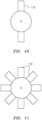
- another example of the feed passage 100 includes an extension 150 with a metering passage 152 and a secondary passage 154 transverse to the metering passage 152.
- the secondary passage 154 is a slot transverse to the metering passage 152. If the foreign object particles that scrub along the surface 122 are of a size to block the metering passage 152, the foreign objects will become stuck on the secondary passage 154 and not be allowed to enter the metering passage 152. Additionally if the entrance of the metering passage 152 becomes blocked with a sizeable foreign object, cooling air can still enter the metering passage 152 through the secondary passage 154.
- another example of the feed passage 100 includes a metering passage 190, and a secondary passage 192 that intersects with the metering passage 190. That is, the secondary passage 192 is a branch from the metering passage 190. In one example, the secondary passage 192 forms an angle of about 30 degrees with respect to the metering passage 190.
- the metering passage 190 may be sized to meter the cooling flow "C" such that the secondary passage 192 need not be specifically sized to meter the cooling flow "C". Should the metering passage 190 become blocked, cooling air may readily pass through the secondary passage 192 then into the metering passage 190 downstream of the entrance 194.
- the secondary passage 192 may be circumferentially located with respect to the metering passage 190 to minimize ingress of the foreign object particles based on the expected cooling flow adjacent each vane 70.
Landscapes
- Engineering & Computer Science (AREA)
- Mechanical Engineering (AREA)
- General Engineering & Computer Science (AREA)
- Turbine Rotor Nozzle Sealing (AREA)
Claims (5)
- Leitschaufelkranz (68; 70) für eine Gasturbinentriebwerkskomponente, umfassend:eine innere Leitschaufelplattform (76; 78) um eine Achse (A);eine äußere Leitschaufelplattform (80; 82) um die Achse (A);mehrere Leitschaufeln (72; 74), die sich zwischen der inneren Leitschaufelplattform (76; 78) und der äußeren Leitschaufelplattform (80; 82) erstrecken, wobei jede der mehreren Leitschaufeln (72; 74) einen Schaufelblattkühlkreislauf (102) enthält, der einen Kühlluftstrom (C) durch einen jeweiligen mehrerer Zufuhrkanäle (100) empfängt; undmehrere Dosierkanäle (170) in der äußeren Leitschaufelplattform (80; 82), wobei jeder der mehreren Dosierkanäle (170) mit einem der mehreren Zufuhrkanäle (100) in Verbindung steht, wobei der Querschnitt jedes der mehreren Dosierkanäle (170) kreisförmig ist; und gekennzeichnet durch:mehrere Sekundärkanäle (172), die in der äußeren Leitschaufelplattform (80; 82) vertieft sind, wobei eine Vielzahl der mehreren Sekundärkanäle (172) mit jedem jeweiligen der mehreren Dosierkanäle (170) in Verbindung steht, wobei jeder der mehreren Sekundärkanäle (172) eine vertiefte Fläche bereitstellt, die gleich einer Fläche des Eingangs (114) jedes der mehreren Dosierkanäle (170) ist; wobeijeder der mehreren Sekundärkanäle (172) ein Schlitz (172) ist; und wobeijeder der Vielzahl von Sekundärkanälen (172) quer zu dem jeweiligen der mehreren Dosierkanäle (170) verläuft.
- Leitschaufelkranz (68; 70) nach Anspruch 1, wobei die mehreren Dosierkanäle (170) und die mehreren Sekundärkanäle (172) innerhalb einer Hakenschiene (84) angeordnet sind, die sich von der äußeren Leitschaufelplattform (80; 82) erstreckt.
- Leitschaufelkranz (68; 70) nach Anspruch 1 oder 2, wobei jeder der mehreren Dosierkanäle (170) und jeder der mehreren Sekundärkanäle (172) in einer Fläche (122) quer zu der Achse (A) gebildet sind.
- Leitschaufelkranz (68; 70) nach Anspruch 3, wobei der Kühlluftstrom (C) in einem Plenum (120) empfangen wird, um an der Fläche (122) entlangzustreichen.
- Leitschaufelkranz (70) nach einem der vorhergehenden Ansprüche, wobei sich der Leitschaufelkranz (70) in einer zweiten Turbinenstufe (46) befindet.
Priority Applications (1)
| Application Number | Priority Date | Filing Date | Title |
|---|---|---|---|
| EP25167390.1A EP4553289A3 (de) | 2018-12-14 | 2019-12-13 | Schaufelring mit blockierverhinderer für kühlbohrung |
Applications Claiming Priority (1)
| Application Number | Priority Date | Filing Date | Title |
|---|---|---|---|
| US16/220,396 US11073024B2 (en) | 2018-12-14 | 2018-12-14 | Shape recessed surface cooling air feed hole blockage preventer for a gas turbine engine |
Related Child Applications (1)
| Application Number | Title | Priority Date | Filing Date |
|---|---|---|---|
| EP25167390.1A Division EP4553289A3 (de) | 2018-12-14 | 2019-12-13 | Schaufelring mit blockierverhinderer für kühlbohrung |
Publications (2)
| Publication Number | Publication Date |
|---|---|
| EP3667028A1 EP3667028A1 (de) | 2020-06-17 |
| EP3667028B1 true EP3667028B1 (de) | 2025-04-02 |
Family
ID=68916356
Family Applications (2)
| Application Number | Title | Priority Date | Filing Date |
|---|---|---|---|
| EP19215954.9A Active EP3667028B1 (de) | 2018-12-14 | 2019-12-13 | Blockierungsverhinderer für kühlluftzufuhrloch mit formvertiefter oberfläche für ein gasturbinentriebwerk |
| EP25167390.1A Pending EP4553289A3 (de) | 2018-12-14 | 2019-12-13 | Schaufelring mit blockierverhinderer für kühlbohrung |
Family Applications After (1)
| Application Number | Title | Priority Date | Filing Date |
|---|---|---|---|
| EP25167390.1A Pending EP4553289A3 (de) | 2018-12-14 | 2019-12-13 | Schaufelring mit blockierverhinderer für kühlbohrung |
Country Status (2)
| Country | Link |
|---|---|
| US (1) | US11073024B2 (de) |
| EP (2) | EP3667028B1 (de) |
Families Citing this family (1)
| Publication number | Priority date | Publication date | Assignee | Title |
|---|---|---|---|---|
| US12297747B1 (en) | 2024-01-08 | 2025-05-13 | Rtx Corporation | Inlet protector for vane coupling hole |
Family Cites Families (18)
| Publication number | Priority date | Publication date | Assignee | Title |
|---|---|---|---|---|
| US3918835A (en) | 1974-12-19 | 1975-11-11 | United Technologies Corp | Centrifugal cooling air filter |
| US4820123A (en) | 1988-04-25 | 1989-04-11 | United Technologies Corporation | Dirt removal means for air cooled blades |
| GB8830152D0 (en) | 1988-12-23 | 1989-09-20 | Rolls Royce Plc | Cooled turbomachinery components |
| GB2343486B (en) | 1998-06-19 | 2000-09-20 | Rolls Royce Plc | Improvemnts in or relating to cooling systems for gas turbine engine airfoil |
| US6343911B1 (en) | 2000-04-05 | 2002-02-05 | General Electric Company | Side wall cooling for nozzle segments for a gas turbine |
| DE50208671D1 (de) | 2001-07-13 | 2006-12-21 | Alstom Technology Ltd | Gasturbinenteil mit Kühlluftbohrung |
| US20070048122A1 (en) | 2005-08-30 | 2007-03-01 | United Technologies Corporation | Debris-filtering technique for gas turbine engine component air cooling system |
| US8702385B2 (en) | 2006-01-13 | 2014-04-22 | General Electric Company | Welded nozzle assembly for a steam turbine and assembly fixtures |
| US7901180B2 (en) | 2007-05-07 | 2011-03-08 | United Technologies Corporation | Enhanced turbine airfoil cooling |
| EP2236746A1 (de) | 2009-03-23 | 2010-10-06 | Alstom Technology Ltd | Gasturbine |
| GB201120273D0 (en) | 2011-11-24 | 2012-01-04 | Rolls Royce Plc | Aerofoil cooling arrangement |
| US9151164B2 (en) * | 2012-03-21 | 2015-10-06 | Pratt & Whitney Canada Corp. | Dual-use of cooling air for turbine vane and method |
| US8961108B2 (en) | 2012-04-04 | 2015-02-24 | United Technologies Corporation | Cooling system for a turbine vane |
| US10240470B2 (en) | 2013-08-30 | 2019-03-26 | United Technologies Corporation | Baffle for gas turbine engine vane |
| EP2990607A1 (de) | 2014-08-28 | 2016-03-02 | Siemens Aktiengesellschaft | Kühlkonzept für Gasturbinenschaufeln |
| US10018062B2 (en) | 2015-07-02 | 2018-07-10 | United Technologies Corporation | Axial transfer tube |
| US10344611B2 (en) | 2016-05-19 | 2019-07-09 | United Technologies Corporation | Cooled hot section components for a gas turbine engine |
| GB2559739A (en) | 2017-02-15 | 2018-08-22 | Rolls Royce Plc | Stator vane section |
-
2018
- 2018-12-14 US US16/220,396 patent/US11073024B2/en active Active
-
2019
- 2019-12-13 EP EP19215954.9A patent/EP3667028B1/de active Active
- 2019-12-13 EP EP25167390.1A patent/EP4553289A3/de active Pending
Also Published As
| Publication number | Publication date |
|---|---|
| US20200190993A1 (en) | 2020-06-18 |
| EP4553289A3 (de) | 2025-08-06 |
| EP4553289A2 (de) | 2025-05-14 |
| EP3667028A1 (de) | 2020-06-17 |
| US11073024B2 (en) | 2021-07-27 |
Similar Documents
| Publication | Publication Date | Title |
|---|---|---|
| EP3667027B1 (de) | Schaufelring für gasturbinentriebwerk und entsprechendes verfahren | |
| US10808546B2 (en) | Gas turbine engine airfoil trailing edge suction side cooling | |
| US20190093567A1 (en) | Seal assembly for a static structure of a gas turbine engine | |
| EP3597875B1 (de) | Partikelabscheider für einen gasturbinentriebwerk und entsprechendes installationsverfahren | |
| EP3246523B1 (de) | Gekühlte schaufel-aussenluftdichtung | |
| US10422244B2 (en) | System for cooling a turbine shroud | |
| EP3428411B1 (de) | Gasturbinentriebwerk und zugehöriges kühlverfahren | |
| US10669887B2 (en) | Vane airfoil cooling air communication | |
| US20160186571A1 (en) | Mixing plenum for spoked rotors | |
| US20160040534A1 (en) | Disk lug impingement for gas turbine engine airfoil | |
| US20170002662A1 (en) | Gas turbine engine airfoil with bi-axial skin core | |
| US11976566B2 (en) | Fatigue resistant blade outer air seal | |
| EP3628818B1 (de) | Prallkühlung für eine gasturbinenmotorkomponente | |
| EP3667028B1 (de) | Blockierungsverhinderer für kühlluftzufuhrloch mit formvertiefter oberfläche für ein gasturbinentriebwerk | |
| US10648351B2 (en) | Gas turbine engine cooling component | |
| EP3667026B1 (de) | Leitschaufelring mit blockierungsverhinderer für zufuhrloch und zugehöriges verfarhren | |
| US11187096B2 (en) | Platform seal | |
| US10961862B2 (en) | Fatigue resistant blade outer air seal | |
| US11098591B1 (en) | Turbine blade with contoured fillet | |
| US20240280025A1 (en) | Air foil with staggered cooling hole configuration | |
| US20160160652A1 (en) | Cooled pocket in a turbine vane platform | |
| EP3293361B1 (de) | Gasturbinentriebwerk und zugehöriges verfahren zur herstellung | |
| US20210108517A1 (en) | Cmc airfoil with cooling holes |
Legal Events
| Date | Code | Title | Description |
|---|---|---|---|
| PUAI | Public reference made under article 153(3) epc to a published international application that has entered the european phase |
Free format text: ORIGINAL CODE: 0009012 |
|
| STAA | Information on the status of an ep patent application or granted ep patent |
Free format text: STATUS: THE APPLICATION HAS BEEN PUBLISHED |
|
| AK | Designated contracting states |
Kind code of ref document: A1 Designated state(s): AL AT BE BG CH CY CZ DE DK EE ES FI FR GB GR HR HU IE IS IT LI LT LU LV MC MK MT NL NO PL PT RO RS SE SI SK SM TR |
|
| AX | Request for extension of the european patent |
Extension state: BA ME |
|
| STAA | Information on the status of an ep patent application or granted ep patent |
Free format text: STATUS: REQUEST FOR EXAMINATION WAS MADE |
|
| 17P | Request for examination filed |
Effective date: 20201216 |
|
| RBV | Designated contracting states (corrected) |
Designated state(s): AL AT BE BG CH CY CZ DE DK EE ES FI FR GB GR HR HU IE IS IT LI LT LU LV MC MK MT NL NO PL PT RO RS SE SI SK SM TR |
|
| RAP1 | Party data changed (applicant data changed or rights of an application transferred) |
Owner name: RAYTHEON TECHNOLOGIES CORPORATION |
|
| STAA | Information on the status of an ep patent application or granted ep patent |
Free format text: STATUS: EXAMINATION IS IN PROGRESS |
|
| 17Q | First examination report despatched |
Effective date: 20210913 |
|
| RAP3 | Party data changed (applicant data changed or rights of an application transferred) |
Owner name: RTX CORPORATION |
|
| GRAP | Despatch of communication of intention to grant a patent |
Free format text: ORIGINAL CODE: EPIDOSNIGR1 |
|
| STAA | Information on the status of an ep patent application or granted ep patent |
Free format text: STATUS: GRANT OF PATENT IS INTENDED |
|
| INTG | Intention to grant announced |
Effective date: 20240311 |
|
| GRAJ | Information related to disapproval of communication of intention to grant by the applicant or resumption of examination proceedings by the epo deleted |
Free format text: ORIGINAL CODE: EPIDOSDIGR1 |
|
| STAA | Information on the status of an ep patent application or granted ep patent |
Free format text: STATUS: EXAMINATION IS IN PROGRESS |
|
| INTC | Intention to grant announced (deleted) | ||
| REG | Reference to a national code |
Ref country code: DE Ref legal event code: R079 Free format text: PREVIOUS MAIN CLASS: F01D0011000000 Ipc: F01D0025120000 Ref document number: 602019068032 Country of ref document: DE |
|
| GRAP | Despatch of communication of intention to grant a patent |
Free format text: ORIGINAL CODE: EPIDOSNIGR1 |
|
| STAA | Information on the status of an ep patent application or granted ep patent |
Free format text: STATUS: GRANT OF PATENT IS INTENDED |
|
| RIC1 | Information provided on ipc code assigned before grant |
Ipc: F01D 9/04 20060101ALI20241001BHEP Ipc: F01D 25/24 20060101ALI20241001BHEP Ipc: F01D 25/14 20060101ALI20241001BHEP Ipc: F01D 25/12 20060101AFI20241001BHEP |
|
| INTG | Intention to grant announced |
Effective date: 20241023 |
|
| GRAS | Grant fee paid |
Free format text: ORIGINAL CODE: EPIDOSNIGR3 |
|
| GRAA | (expected) grant |
Free format text: ORIGINAL CODE: 0009210 |
|
| STAA | Information on the status of an ep patent application or granted ep patent |
Free format text: STATUS: THE PATENT HAS BEEN GRANTED |
|
| AK | Designated contracting states |
Kind code of ref document: B1 Designated state(s): AL AT BE BG CH CY CZ DE DK EE ES FI FR GB GR HR HU IE IS IT LI LT LU LV MC MK MT NL NO PL PT RO RS SE SI SK SM TR |
|
| REG | Reference to a national code |
Ref country code: GB Ref legal event code: FG4D |
|
| REG | Reference to a national code |
Ref country code: CH Ref legal event code: EP |
|
| REG | Reference to a national code |
Ref country code: IE Ref legal event code: FG4D |
|
| REG | Reference to a national code |
Ref country code: DE Ref legal event code: R096 Ref document number: 602019068032 Country of ref document: DE |
|
| REG | Reference to a national code |
Ref country code: NL Ref legal event code: MP Effective date: 20250402 |
|
| PG25 | Lapsed in a contracting state [announced via postgrant information from national office to epo] |
Ref country code: NL Free format text: LAPSE BECAUSE OF FAILURE TO SUBMIT A TRANSLATION OF THE DESCRIPTION OR TO PAY THE FEE WITHIN THE PRESCRIBED TIME-LIMIT Effective date: 20250402 |
|
| REG | Reference to a national code |
Ref country code: AT Ref legal event code: MK05 Ref document number: 1781443 Country of ref document: AT Kind code of ref document: T Effective date: 20250402 |
|
| PG25 | Lapsed in a contracting state [announced via postgrant information from national office to epo] |
Ref country code: FI Free format text: LAPSE BECAUSE OF FAILURE TO SUBMIT A TRANSLATION OF THE DESCRIPTION OR TO PAY THE FEE WITHIN THE PRESCRIBED TIME-LIMIT Effective date: 20250402 Ref country code: PT Free format text: LAPSE BECAUSE OF FAILURE TO SUBMIT A TRANSLATION OF THE DESCRIPTION OR TO PAY THE FEE WITHIN THE PRESCRIBED TIME-LIMIT Effective date: 20250804 Ref country code: ES Free format text: LAPSE BECAUSE OF FAILURE TO SUBMIT A TRANSLATION OF THE DESCRIPTION OR TO PAY THE FEE WITHIN THE PRESCRIBED TIME-LIMIT Effective date: 20250402 |
|
| REG | Reference to a national code |
Ref country code: LT Ref legal event code: MG9D |
|
| PG25 | Lapsed in a contracting state [announced via postgrant information from national office to epo] |
Ref country code: GR Free format text: LAPSE BECAUSE OF FAILURE TO SUBMIT A TRANSLATION OF THE DESCRIPTION OR TO PAY THE FEE WITHIN THE PRESCRIBED TIME-LIMIT Effective date: 20250703 Ref country code: NO Free format text: LAPSE BECAUSE OF FAILURE TO SUBMIT A TRANSLATION OF THE DESCRIPTION OR TO PAY THE FEE WITHIN THE PRESCRIBED TIME-LIMIT Effective date: 20250702 |
|
| PG25 | Lapsed in a contracting state [announced via postgrant information from national office to epo] |
Ref country code: PL Free format text: LAPSE BECAUSE OF FAILURE TO SUBMIT A TRANSLATION OF THE DESCRIPTION OR TO PAY THE FEE WITHIN THE PRESCRIBED TIME-LIMIT Effective date: 20250402 |
|
| PG25 | Lapsed in a contracting state [announced via postgrant information from national office to epo] |
Ref country code: BG Free format text: LAPSE BECAUSE OF FAILURE TO SUBMIT A TRANSLATION OF THE DESCRIPTION OR TO PAY THE FEE WITHIN THE PRESCRIBED TIME-LIMIT Effective date: 20250402 |
|
| PG25 | Lapsed in a contracting state [announced via postgrant information from national office to epo] |
Ref country code: HR Free format text: LAPSE BECAUSE OF FAILURE TO SUBMIT A TRANSLATION OF THE DESCRIPTION OR TO PAY THE FEE WITHIN THE PRESCRIBED TIME-LIMIT Effective date: 20250402 |
|
| PG25 | Lapsed in a contracting state [announced via postgrant information from national office to epo] |
Ref country code: AT Free format text: LAPSE BECAUSE OF FAILURE TO SUBMIT A TRANSLATION OF THE DESCRIPTION OR TO PAY THE FEE WITHIN THE PRESCRIBED TIME-LIMIT Effective date: 20250402 |
|
| PG25 | Lapsed in a contracting state [announced via postgrant information from national office to epo] |
Ref country code: RS Free format text: LAPSE BECAUSE OF FAILURE TO SUBMIT A TRANSLATION OF THE DESCRIPTION OR TO PAY THE FEE WITHIN THE PRESCRIBED TIME-LIMIT Effective date: 20250702 |
|
| PG25 | Lapsed in a contracting state [announced via postgrant information from national office to epo] |
Ref country code: IS Free format text: LAPSE BECAUSE OF FAILURE TO SUBMIT A TRANSLATION OF THE DESCRIPTION OR TO PAY THE FEE WITHIN THE PRESCRIBED TIME-LIMIT Effective date: 20250802 |
|
| PG25 | Lapsed in a contracting state [announced via postgrant information from national office to epo] |
Ref country code: LV Free format text: LAPSE BECAUSE OF FAILURE TO SUBMIT A TRANSLATION OF THE DESCRIPTION OR TO PAY THE FEE WITHIN THE PRESCRIBED TIME-LIMIT Effective date: 20250402 |
|
| REG | Reference to a national code |
Ref country code: DE Ref legal event code: R097 Ref document number: 602019068032 Country of ref document: DE |
|
| PGFP | Annual fee paid to national office [announced via postgrant information from national office to epo] |
Ref country code: DE Payment date: 20251126 Year of fee payment: 7 |
|
| PGFP | Annual fee paid to national office [announced via postgrant information from national office to epo] |
Ref country code: GB Payment date: 20251119 Year of fee payment: 7 |
|
| PG25 | Lapsed in a contracting state [announced via postgrant information from national office to epo] |
Ref country code: SM Free format text: LAPSE BECAUSE OF FAILURE TO SUBMIT A TRANSLATION OF THE DESCRIPTION OR TO PAY THE FEE WITHIN THE PRESCRIBED TIME-LIMIT Effective date: 20250402 Ref country code: DK Free format text: LAPSE BECAUSE OF FAILURE TO SUBMIT A TRANSLATION OF THE DESCRIPTION OR TO PAY THE FEE WITHIN THE PRESCRIBED TIME-LIMIT Effective date: 20250402 |
|
| PGFP | Annual fee paid to national office [announced via postgrant information from national office to epo] |
Ref country code: FR Payment date: 20251120 Year of fee payment: 7 |
|
| PG25 | Lapsed in a contracting state [announced via postgrant information from national office to epo] |
Ref country code: CZ Free format text: LAPSE BECAUSE OF FAILURE TO SUBMIT A TRANSLATION OF THE DESCRIPTION OR TO PAY THE FEE WITHIN THE PRESCRIBED TIME-LIMIT Effective date: 20250402 |
|
| PG25 | Lapsed in a contracting state [announced via postgrant information from national office to epo] |
Ref country code: EE Free format text: LAPSE BECAUSE OF FAILURE TO SUBMIT A TRANSLATION OF THE DESCRIPTION OR TO PAY THE FEE WITHIN THE PRESCRIBED TIME-LIMIT Effective date: 20250402 |
|
| PG25 | Lapsed in a contracting state [announced via postgrant information from national office to epo] |
Ref country code: RO Free format text: LAPSE BECAUSE OF FAILURE TO SUBMIT A TRANSLATION OF THE DESCRIPTION OR TO PAY THE FEE WITHIN THE PRESCRIBED TIME-LIMIT Effective date: 20250402 Ref country code: SK Free format text: LAPSE BECAUSE OF FAILURE TO SUBMIT A TRANSLATION OF THE DESCRIPTION OR TO PAY THE FEE WITHIN THE PRESCRIBED TIME-LIMIT Effective date: 20250402 |
|
| PG25 | Lapsed in a contracting state [announced via postgrant information from national office to epo] |
Ref country code: IT Free format text: LAPSE BECAUSE OF FAILURE TO SUBMIT A TRANSLATION OF THE DESCRIPTION OR TO PAY THE FEE WITHIN THE PRESCRIBED TIME-LIMIT Effective date: 20250402 |
|
| PLBE | No opposition filed within time limit |
Free format text: ORIGINAL CODE: 0009261 |
|
| STAA | Information on the status of an ep patent application or granted ep patent |
Free format text: STATUS: NO OPPOSITION FILED WITHIN TIME LIMIT |
|
| REG | Reference to a national code |
Ref country code: CH Ref legal event code: L10 Free format text: ST27 STATUS EVENT CODE: U-0-0-L10-L00 (AS PROVIDED BY THE NATIONAL OFFICE) Effective date: 20260211 |
|
| 26N | No opposition filed |
Effective date: 20260105 |